

Converters.TV 15532 Operation Manual
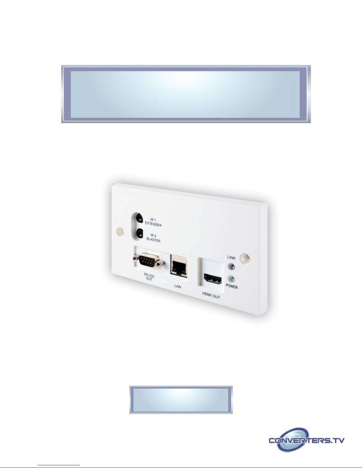
HDBaseT HDMI over CAT5e/6/7 Wallplate
Receiver w/ 24vPoC & LAN Serving - # 15532
Operation Manual

Introduction
Applications
Features
The HDMI over Single CAT5e/6/7 Wall-plate Receiver is designed to
receive uncompressed video, audio and IR control data from a compatible
transmitter over a single run of CAT5e/6/7 cable at a distance of up to 100
meters. It has the added benefit of control through the built-in RS-232 and
IR ports and a bi-directional LAN serving connection. Additionally, it can be
powered by a compatible transmitter unit via the Power over Cable (PoC)
functionality allowing for greater flexibility in installations.
• Extend an HDMI signal to a remote location
• Household entertainment sharing and control
• Showroom display and control
• Classroom display and control
• HDMI with 3D, 4K2K support, HDCP and DVI compliant
• Simultaneous tranmisson of uncompressed data over a single 100m
CAT5e/6/7 cable (70m for 4K2K signals)
• Uncompressed video support up to 1080p@60 Hz/36-bit
• High definition audio support up to LPCM 7.1CH, Dolby TrueHD, Dolby
Digital Plus and DTS-HD Master Audio
• HDBaseT™ 5PlayT™ convergence: uncompressed high definition Video
and Audio, LAN serving, Power over Cable (PoC) and RS-232/IR control
• Supports HDCP repeater and CEC bypass functions
• Easy to install wall plate design
Note:
1. This system was tested with CAT6/23AWG and CAT5e/24AWG cables,
results may vary with cables of a different specification.
2. The PoC function requires a compatible Transmitter unit.
Transmitters from other brands may not be compatible.
3. For playback of 4K2K HDMI source signals, a 4K2K capable display
and High Speed HDMI cables are required.
System
Requirements
• HDMI equipped source device (connected with HDMI cables) or DVI
equipped source (connected with DVI to HDMI cables)
• HDMI equipped display (TV or monitor) or AN HDMI equipped AV
receiver, connected with HDMI cables
• Industry standard CAT5e/6/7 cables
• Compatible PoC HDBaseT™ Receivers
Operation
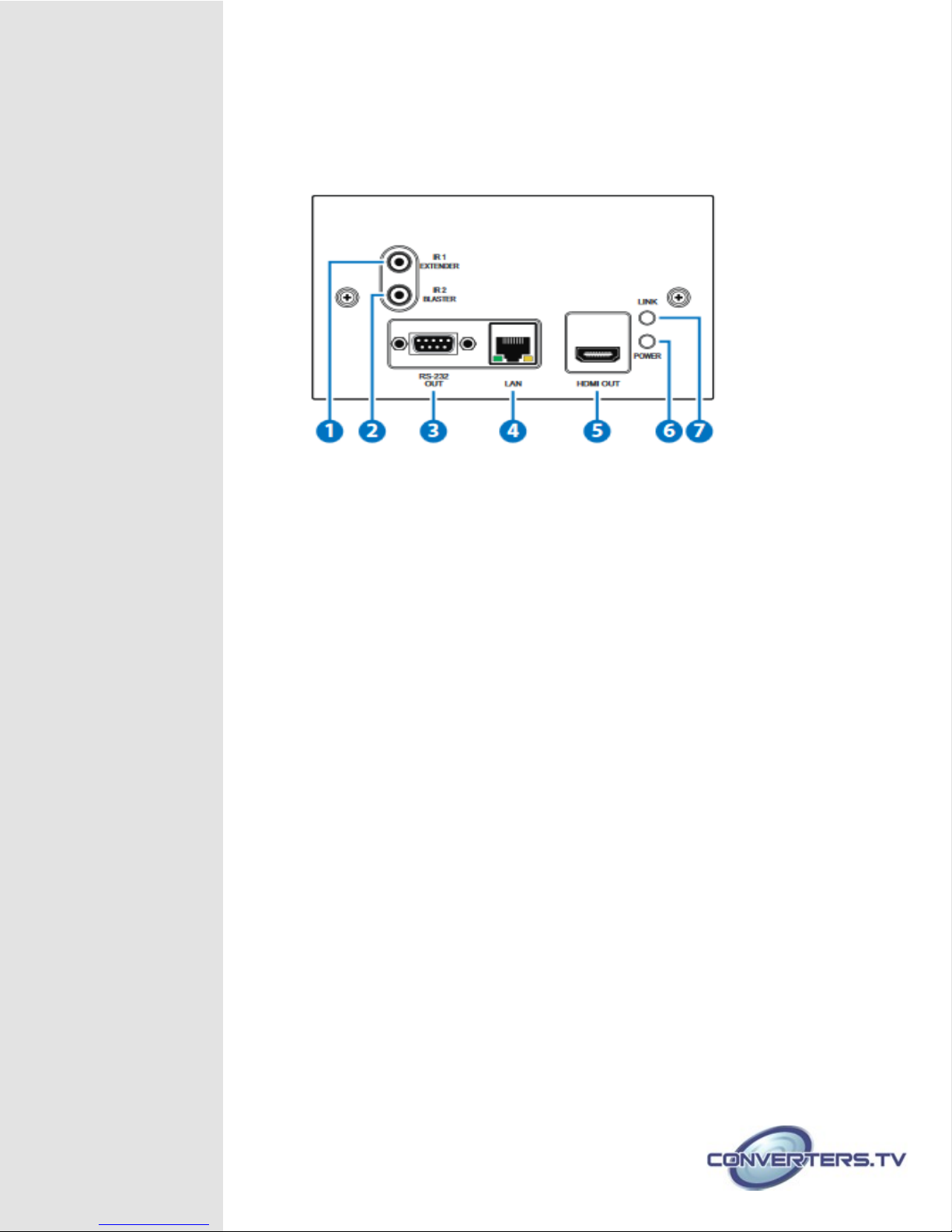
Controls and Front Panel
Functions
1. IR 1 EXTENDER:
Connect an IR Extender cable for IR signal reception. Signals received will
be transmitted from any IR blaster connected to the transmitter unit.
Ensure that the remote being used is within the direct line-of-sight of the IR
Extender
2. IR 2 BLASTER:
Connect an IR Blaster cable for IR signal transmission.
IR signals received by an IR extender connected to the transmitter unit will
be transmitted by this blaster. Place the IR Blaster in direct line-of-sight of
the equipment to be controlled
3. RS-232 OUT:
Connect to the device that is to be controlled (via D-sub 9-pin female
cable) by RS-232 commands.
4. LAN:
Connect to an active network for LAN serving. When the transmitter or any
compatible LAN equipped receivers are connected to a network, this
allows the network access (including internet access if available) to be
shared between the receiver and all connected receivers. Connect any
Ethernet equipped device e.g. a Smart TV or games console to the LAN
port of a receiver for that device to share the network/internet access.
5. HDMI OUT:
Connect to a HDMI equipped TV/monitor for display of the HDMI input
source signal.
6. POWER LED:
This LED will illuminate when the device is connected to a power supply or
powered by another unit via PoC.
7. LINK LED:
This LED will illuminate when both the source connected to the transmitter
and the display connected to the receiver are connected.
.
 Loading...