

Converters.TV 15464 Operation Manuals
HDMI/Displayport/VGA to
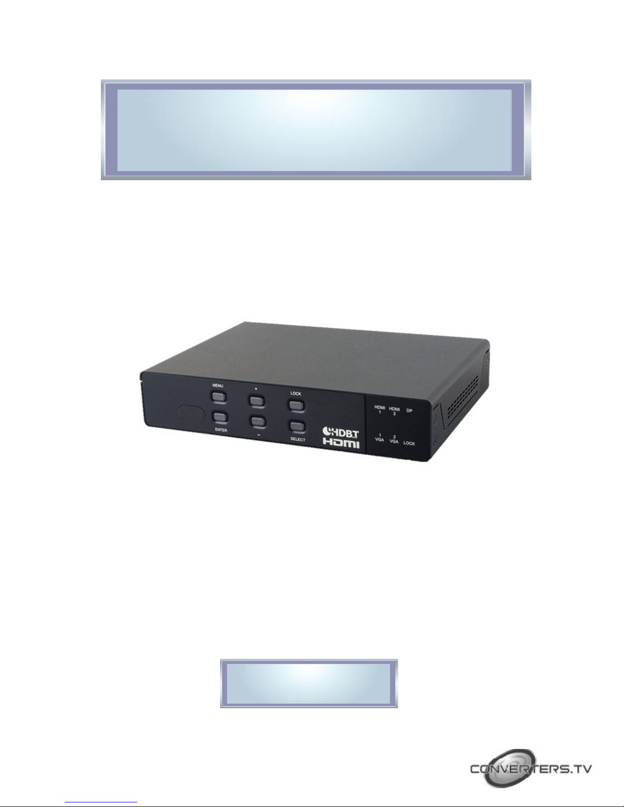
HDMI/HDBaseT Scaler ID# 15464
Operation Manual

Introduction
Features
The Multi-inputs with HDMI and HDBT output scaler box supports 5
inputs of HDMI, VGA and DisplayPort. The input source is capable to
switch and scale to adopt resolution then transmit over HDMI and
HDBaseT. The HDTV resolution is achievable. Meanwhile, it offer
flexibility application of audio which includes unbalance audio, MIC In
and line out. The professional 48V phantom microphone is compatible.
The audio DSP engine offer auto-mixer and auto-gain control to mix or
reduce background audio in order to enhance major audio source. The
system could be controlled and configure by easily operation of Telnet,
WebGUI, IR remote and RS-232. This scaler box is a suitable solution
for presentation purpose at classroom and conference room.
• HDMI and HDCP compliant
• Supports multi inputs: 2 x HDMI, 2 x VGA and 1 x Display port, 3 x
unbalance audio, 1 x MIC In (48V phantom selection)
• Scaler synchronous outputs to 1 x HDMI, and 1 x CAT5e/6/7
• Supports HDTV resolutions up to 1080p (VGA to WUXGA)
• Supports Internal EDID
• Supports pass-through of PCM 2CH
• Audio DSP offer auto mixer and auto gain control for mix or reduce
background audio
• Device could be controlled via WebGUI, IR remote and RS-232
• Supports IR In and IR Out to receive or transmit IR signal from
compatible receiver with bi-directional RS-232 control
• Input control provides direct input source selection
• Support output resolutions up to 1080p
Applications
• Analog and digital source integration
• Upscaling standard definition video for high-definition displays
• Conference centers
• Lecture halls
• Schools and universities
System Requirements
Input source equipment such as Blu-ray/DVD players or PC/Laptop and
output to displays, AV Receivers or active speakers.
Operating Functions
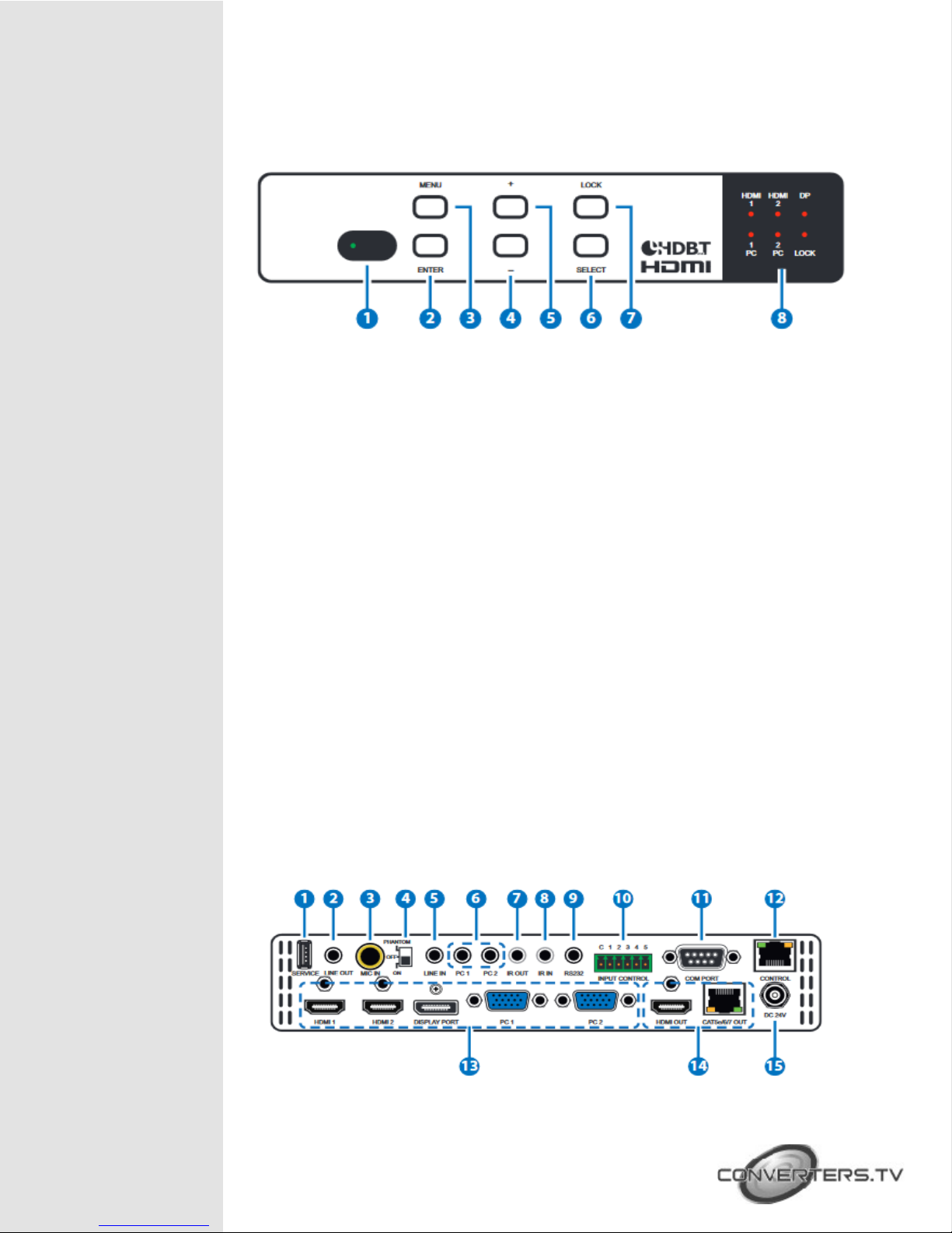
and Controls Front Views
1. IR Window:
Receiving IR signal from remote control unit which come with scaler
box.
2. “Enter” button:
Press this button to confirm the selection of On Screen Display (OSD)
menu.
3. “Menu” button:
Press this button to access to On Screen Display (OSD) menu.
4. “-“ (Minus) button:
Press button to navigate down on OSD menu.
Press "Menu" and "+" will direct output of XGA60(1024x768) and
"Menu" and "-" for 720p60.
5. “+” (Plus) button:
Press button to navigate up on OSD menu.
6. “Select” button:
Press this button for source selection. The active source will be indicator
on LEDs at front panel.
7. “Lock” button:
Press this button to lock front panel and press again to unlock.
8. LEDs:
This LED for selected source indication. The LED for the selected
source will illuminate for indicating active source accordingly.
Rear Views
1. Service:
The service slot is for firmware update via USB driver.
2. Line out:
Connects with amplifier for audio source broadcasting.
3. MIC IN:
Plug microphone in for audio source output. The phantom
microphone is well supported.
4. Phantom on/off:
Arrange the slide switch to “on” for condenser microphone (5V) or
“phantom” for professional 48V phantom microphone. When slide
switch arrange to “off”, the audio output will be mute.
5. Line In:
Select the external analog audio on OSD and insert the audio to
HDMI or DP video source then output to display.
6. PC1 / PC2:
When video source is PC, the PC audio cable shall connect in this
jack for PC audio source output with video to display.
7. IR Out:
Connect with supplied IR blaster cable to sending IR single which
comes from remote control unit to compatible Receivers.
8. IR IN:
Connect with supplied IR extender cable to receive the IR signal from
the included IR remote. Ensure that the remote is within the direct
line-of-sight of the IR extender.
9. RS-232:
For sending RS-232 command to compatible Receivers.
10. Input Control:
This input control reserving for direct source input selection. Connect
ground pin (mark as C on panel) with following pin number for
individual source selection.
11. Com Port:
Connect with D-Sub 9 pin cable with PC or laptop for this scaler box
controlled by RS-232 commands.
12. Control:
This port is the link for WebGUI control; connect to an active Ethernet
link with an RJ45 terminated cable.
13. Input Sources:
Pin Number Source
Pin 1 HDMI 1
Pin 2 HDMI 2
Pin 3 Display Port
Pin 4 PC1
Pin 5 PC2
RS-232
Command List
1. PC 1 & PC2: Connect to a PC/Laptop source for video signal input
with D-Sub 15pin cable.
2. Display port: Connect to a PC / Laptop source for video signal
input.
3. HDMI 1 & HDMI2: Connect to HDMI sources such as Blu-ray/DVD
player for both video and audio signal.
14. Output:
1. CAT5e/6/7 Out: Connects with compatible Receiver for video
and / or audio output.
2. HDMI Out: Connect to an HDMI display or AV Receiver for
video and/or audio output.
15. DC 24V:
Plug the 24V DC power supply into the unit and connect the adaptor to
an AC outlet.
Command Format:
1. <COMMAND><CR><LF>
2. <S><SPACE><COMMAND><CR><LF>
3. <R><SPACE><COMMAND><CR><LF>
4. <S><SPACE><COMMAND><SPACE><PARAMETER><CR><LF
Command Format
Following command (from item 2) omits <SPACE><CR><LF> :
Item Command Description
1
2
?<CR><LF>
S<SPACE>factoryreset<CR><LF>
List all commands
Return to factory default setting
3 r version Read FW version
4 r source Read existing input source
5 s source 0
6 r lock
7 s lock 1
Set up HDMI 1 input (0:HDMI 1/
1:HDMI2 / 2:DP / 3: VGA1 /
4:VGA2)
Read lock status of manual
selection button
Set up manual selection button lock
status (0: cancel press button lock)
8 r output Read output resolution
9 s output 0
Set up output resolution at 640x480
(1:800x600, 2:1024x768,
3:1280x768, 4:1360x768,
5:1280x720, 6:1280x800,
7:1280x1024, 8:1440x900,
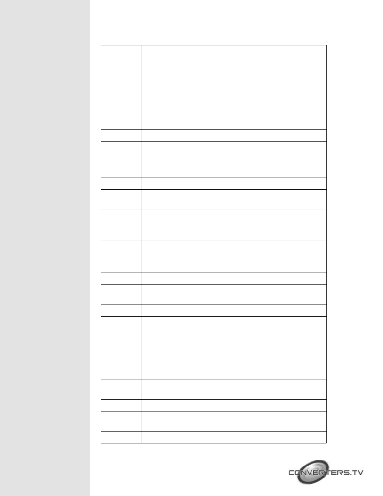
9:1400x1050, 10:1680x1050,
11:1600x1200, 12:1920x1080,
13:1920x1200, 14:720x480P,
15:1280x720P60,
16:1920x1080I60,
17:1920x1080P60,
18:720x576P, 19:1280x720P50,
20:1920x1080I50,
21:1920x1080P50,
22:Native OUT1, 23:Native OUT2)
10 r size Read output picture size
11 S size 0
12 r hdmi1-hdcp
13 s hdmi1-hdcp 0
14 r hdmi2-hdcp
15 s hdmi2-hdcp 0
16 r dp-hdcp
17 s dp-hdcp 0
18 r contrast
19 s contrast 0
20 r brightness
21 s brightness 0
Set up over-scan for output picture
(1:Full/2:Follow-Input/3:Panscan/4:LetterBox/5:Under2/6:Under1)
Read HDCP status for HDMI 1
Active HDCP for HDMI 1 (1:disable
HDCP for HDMI2)
Read HDCP status for HDMI 2
Active HDCP for HDMI 2 (1:disable
HDCP for HDMI2)
Read HDCP status for Display Port
Active HDCP for Display Port
(1:disable HDCP for DP)
Read contrast status
Set up contrast 0 (contrast could be
from 0 to 60)
Read brightness status
Set up brightness 0 (brightness
adjustment from 0 to 60)
22 r color-r
23 s color-r 0
24 r color-g
25 s color-g 0
26 r color-b
27 s color-b 0
28 r hue
Read color-red status
Set up color-red 0 (color-red
adjustment from 0 to 1023)
Read color-green status
Set up color-green 0 (color-green
adjustment from 0 to 1023)
Read color-blue status
Set up color-blue 0 (color-blue
adjustment from 0 to 1023)
Read hue status
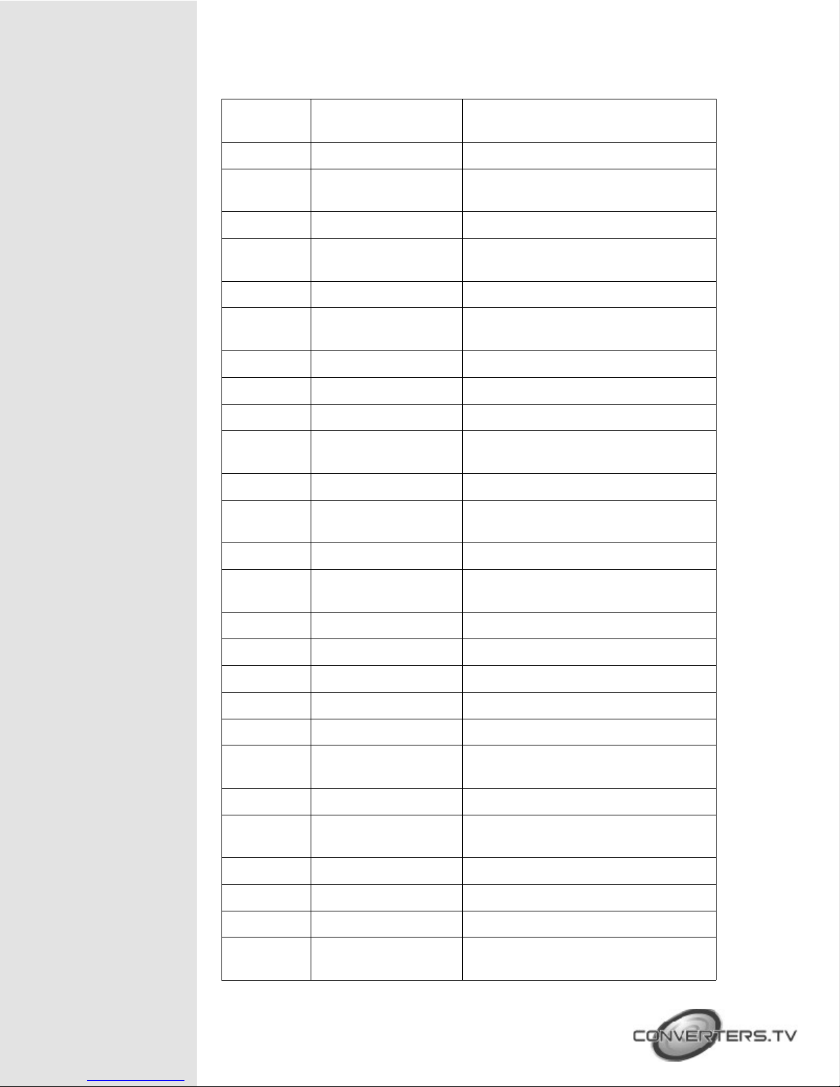
29 s hue 0
Set up hue 0 (hue adjustment from
0 to 60)
30 r saturation
31 s saturation 0
32 r sharpness
33 s sharpness 0
34 r nr
35 s nr 0
36 s pc-auto 1
37 s pc-reset 1
38 r pc-h-pos
39 s pc-h-pos 0
40 r pc-v-pos
41 s pc-v-pos 0
Read color-blue status
Set up color-blue 0 (color-blue
adjustment from 0 to 1023)
Read hue status
Set up sharpness 0 (sharpness
adjustment from 0 to 30)
Read status of noise reduction
Set up noise reduction at off (1:Low
/ 2:Middle / 3:High)
Enable auto function of PC
Return to default setting of PC
Read horizontal position of PC
Set up horizontal position 0 of PC (
position adjustment from 0 to 60)
Read vertical position of PC
Set up vertical position 0 of PC
( position adjustment from 0 to 60)
42 r pc-phase
43 s pc-phase 0
44 r pc-wxga-xga
45 s pc-wxga-xga o
46 r mixer
47 s mixer 0
48 r mic-vol
49 s mic-vol 0
50 r delay
51 s delay 0
52 r mute
53 s mute 0
54 r out-vol
55 s out-vol 0
Read PC phase
Set up PC phase at 0 ( PC phase
adjustment from 0 to 30)
Read PC WXGA/XGA status
Set up WXGA(1:XGA)
Read mixer status
Set up mixer off (1:MIC)
Read microphone volume
Set up microphone volume 0
(Volume adjustment form 0 to 100)
Read audio delay status
Set up audio delay off (1: 40ms /
2:110ms / 3:150ms)
Read audio mute status
Set up audio un-mute (1:Mute)
Read volume of video output
Set up volume of video output at 0 (
video volume adjustment from 0 to
 Loading...