

Converters.TV 15429 Operation Manual
UHD 4x2 4K2K Sw i tch with 6G
capability - ID# 15429
Operation Manual

Introduction
Features
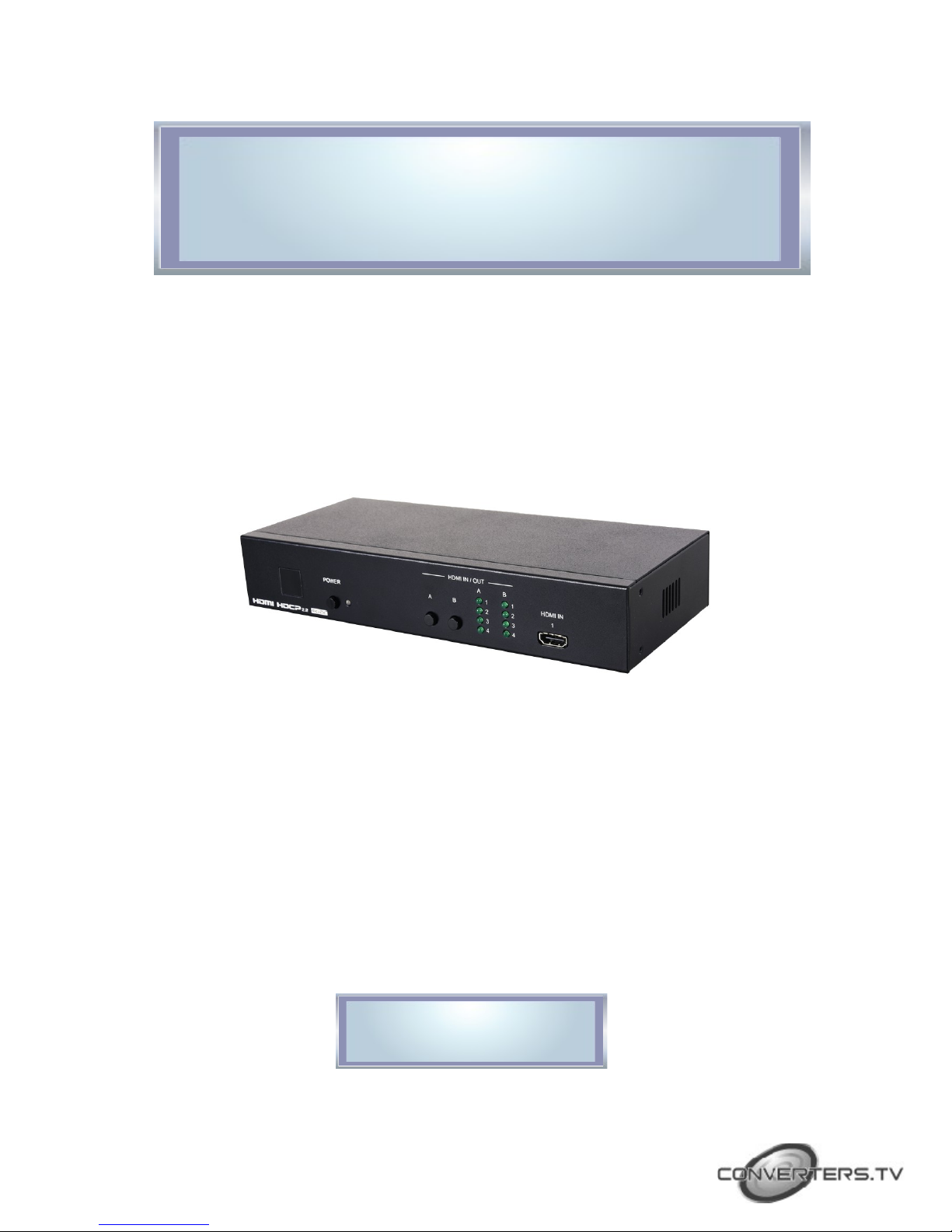
This 6G UHD 4 by 2 HDMI Matrix allows the customer to route up to four
6G HDMI input signals to any of two 6G HDMI outputs. This unit
supports 4K@60Hz (YUV 4:4:4), 48-bit Deep Color, HDR (High Dynamic
Range), HD audio formats and other features defined by the HDMI 2.0
specification. Five pre-defined internal EDIDs and two external EDID
options are available for EDID management. The unit provides intuitive
front panel controls as well as RS-232, telnet, WebGUI and IR remote
control options.
• HDMI 2.0 and DVI 1.0 compliant
• HDCP 1.4 and 2.2 compliant
• Supports the matrix routing of four 6G HDMI inputs to two 6G
HDMI outputs
• Supports HDTV resolutions up to 4K UHD
(3840x2160@24/25/30/50/60 & 4096x2160@24/25/30/50/60Hz)
• Maximum data rate up to 6Gbps with Deep Color support up to
48-bit at 1080p
• Supports pass-through of HD audio formats including LPCM,
Dolby Digital, DTS, Dolby Digital Plus, Dolby TrueHD, Dolby
Atmos and DTS-HD Master Audio
• Supports EDID management via five pre-defined internal EDIDs
and two external EDID options
• Multiple control interfaces including RS-232, telnet, WebGUI and
IR remote
Applications
System Requirements
• Entertainment Room & Home Theater
• Show Room & Demo Room
• Class room & Lecture Hall Presentations
• Public Commercial Display
• HDMI source equipment such as media players, video game
consoles or set-top boxes.
• HDMI receiving equipment such as HDTVs, monitors or audio
amplifiers.
• The use of “Premium High Speed HDMI” cables is highly
recommended.
Operating Functions
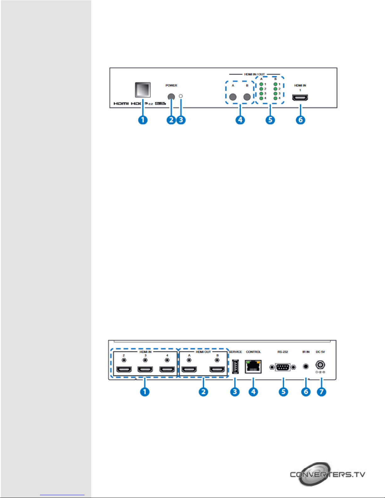
and Controls Front Panel
1. IR window:
Accepts IR signals from the included IR remote for control of this unit
only.
2. POWER:
Press this button to power on the unit or place it into stand-by mode.
Note:
Ethernet and RS-232 remain active while the unit is in stand-by mode.
3. Power indicator:
This LED will illuminate GREEN to indicate the unit is on and receiving
power. When the unit is in stand-by mode the LED will illuminate RED.
4. HDMI Out routing buttons “A” & “B”:
Press either of these buttons to sequentially switch through the available
inputs for the associated output.
5. HDMI In indicator “1&2&3&4”:
The LED in each column will illuminate GREEN to indicate which source
is currently selected for each output
6. HDMI In:
Connect to HDMI source equipment such as a media player, game
console or set-top box. DVI sources are also supported with the use of
an HDMI to DVI adapter.
Rear Panel
1. HDMI In :
Connect to HDMI source equipment such as a media player, game
console or set-top box. DVI sources are also supported with the use of
an HDMI to DVI adapter

Remote Control
2. HDMI Out:
Connect to HDMI TVs, monitors or amplifiers for digital video and audio
output. DVI sources are also supported with the use of an HDMI to DVI
adapter
3. SERVICE:
This slot (USB 2.0) is reserved for firmware update use only.
Please plug in a USB thumb drive containing the new firmware to
update the unit.
4. CONTROL:
Connect directly, or through a network switch, to your PC/laptop to
control the unit via telnet/WebGUI.
5. RS-232:
Connect directly to your PC/laptop to send RS-232 commands to control
the unit.
6. IR IN:
Connect to the provided IR Extender to extend the IR control range of
the unit. Ensure that the remote being used is within direct line-of-sight
of the IR Extender.
7. DC 5V:
Plug the 5V DC power adapter into the unit and connect it to an AC wall
outlet for power
1. POWER:
Press Power key to turn on the
device or set to standby mode.
WebGUI
2. OUTPUT A1~A4 & B1~B4:
Press these buttons
to change the routing of output A/B
Install the IP Discovery Tool:
1. Please obtain the Device Discovery software from your authorized
dealer and save it in a directory where you can easily find it.
Note: The unit’s default IP address is 192.168.1.50
2. Connect the unit and your PC/Laptop to the same active network
and execute the Device Discovery software. Click on “Find
Devices on Network” and a list of devices connected to the local
network will show up indicating their current IP address
3. By clicking on one of the listed devices you will be presented with
WebGUI Control
Page
the network details of that particular device. If you choose, you can alter
the static IP network settings for the device, or switch the unit into DHCP
mode to automatically obtain proper network settings from a local DHCP
server. To switch to DHCP mode, please select DHCP from the IP mode
drop-down, then click “Save” followed by “Reboot”.
4. Once you are satisfied with the network settings, you may use them to
connect via telnet or WebGUI. The network information window provides
a convenient link to launch the WebGUI directly.
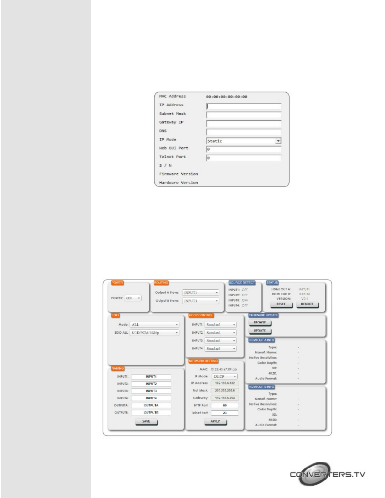
All functions, including power, input selection, EDID management,
HDCP management, Ethernet settings, and reset/firmware functions,
are presented on a single web page to allow for intuitive operation.
The individual functions will be introduced in the following sections.
 Loading...