

Converters.TV 15222, 15223 Operation Manual
HDBaseT HDMI over Single CAT5e/6/7
Transmitter and Receiver with
LAN/PoE/RS-232/IR - # 15222 / #15223
Operation Manual

Introduction
Features
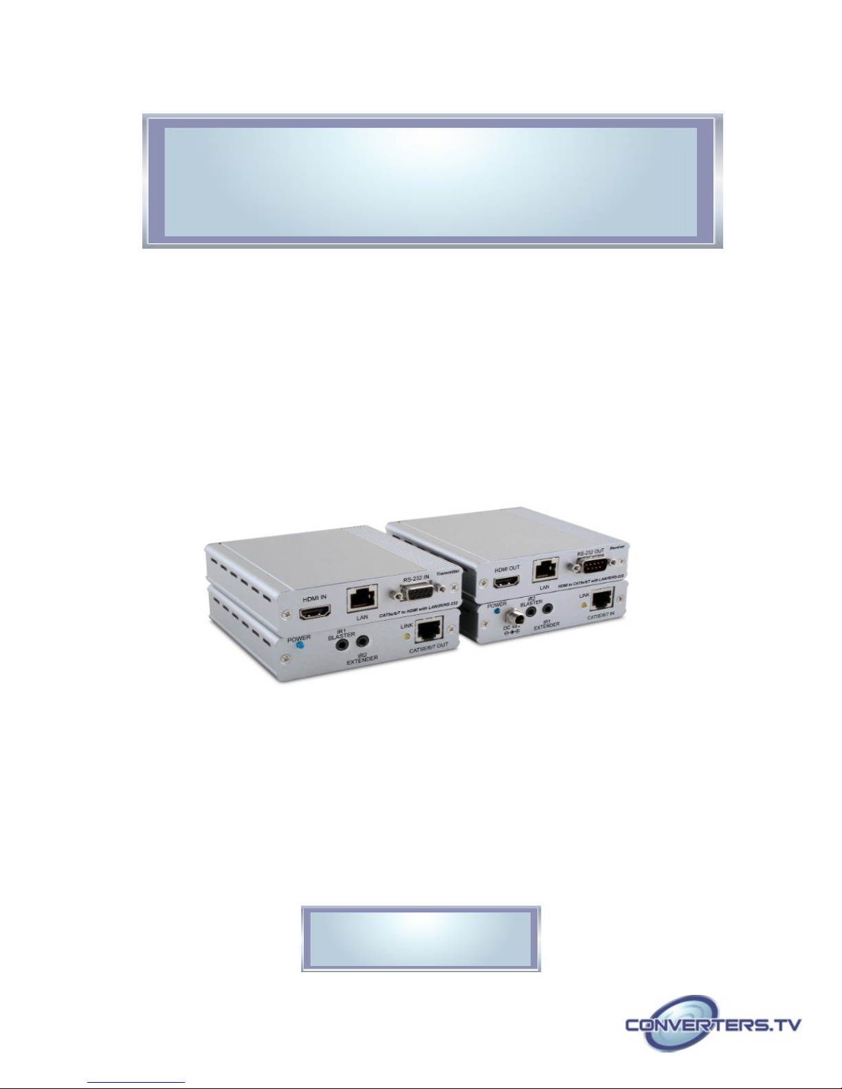
The CH-2507 Transmitter and Receiver set can send uncompressed
audio/video and IP data over a single run of CAT5e/6/7 cable at a distance
of up to 100 meters with the added benefit of control through the built-in RS232 and IR ports and a bidirectional LAN serving connection. The transmitter
(PD) can be powered by the PoE (48V) function of the receiver (PSE),
allowing for greater flexibility in installations.
• HDMI with 3D, 4K×2K support, HDCP and DVI compliant
• Simultaneous transmission of uncompressed data over a single
CAT5e/6/7 cable up to 100m/328ft
• HDBaseT™ 5Play™ convergence: uncompressed high definition
Video and Audio, LAN serving, Power over Ethernet and RS-232/IR control
• Uncompressed video support up to 1080p@60 Hz/36-bit
• High definition audio support up to LPCM 7.1CH, Dolby
TrueHD, Dolby Digital Plus and DTS-HD Master Audio
• Supports audio sampling rates of 32kHz to 192kHz
• Support standard 48V power from Receiver (PSE) to Transmitter (PD)
• Supports CEC bypass
• Installation friendly
Note:
1. This system was tested with CAT5e/6/7 cables, results may vary
with cables of a different specification.
2. The standard 48V PoE function is designed for powering
compatible Transmitter units only—non-PoE Transmitters will need
their own power supply. Transmitters from other brands may not
be compatible.
3. For playback of 4K×2K HDMI source signals, a 4K×2K capable
display and High Speed HDMI cables are required.
Applications
• 48V PoE from Receiver (PSE) to Transmitter (PD)
• Household entertainment sharing and control
• Lecture room display and control
• Showroom display and control
• Meeting room presentation and control
• Classroom display and control
System
Requirements
HDMI source equipment such as a DVD/Blu-ray player and HDMI equipped
output display (TV or monitor).
Operation Controls
and Functions
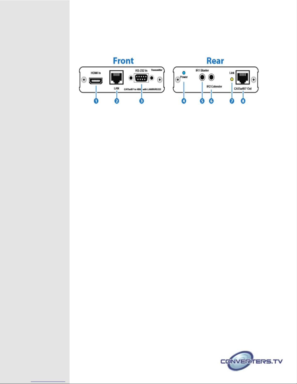
Transmitter Front and Rear Panels
1. HDMI IN:
Connect to HDMI source equipment such as a DVD or Blu-ray player.
2. LAN:
Connect to an active network for LAN serving. This allows network access
(including internet access if available) to be shared to any device (e.g. a
smart TV or games console) connected to the LAN port of the receiver
Warning: DO NOT connect the LAN connection to the CAT5e/6/7
output, doing so may trigger a power shut down and may damage the
device.
3. RS-232 IN:
Connect to a PC or laptop with D-Sub 9 pin male cable for the transmission
of RS-232 commands.
4. POWER LED:
This blue LED will illuminate when the device is connected to a power
supply.
5. IR1 BLASTER:
Connect an IR Blaster cable for IR signal transmission.
IR signals received by an IR extender connected to the receiver unit will be
transmitted by this blaster. Place the IR Blaster in direct line-of-sight of the
equipment to be controlled.
6. IR2 EXTENDER:
Connect an IR Extender cable for IR signal reception.
Signals received will be transmitted from any IR blaster connected to the
receiver unit. Ensure that the remote being used is within the direct line-ofsight of the IR Extender.
7. LINK LED:
The yellow LED will illuminate when both the source connected to the
transmitter and the display connected to the receiver are connected. The
LED will blink regularly to indicate that no signal is being received from the
display and irregularly to indicate that an error has occurred.
8. CAT5e/6/7 OUT:
Connect to the receiver unit with a Single CAT5e/6/7 cable for transmission
of all data signals.
 Loading...