

Page 1

User Manual of CSL RTLS System
CS3151 Tag
CS5111LP Reader
CS5113LP Reader with Ethernet Bridge
1
Page 2

Table of Content
User Manual of CSL RTLS System...............................................................................1
Introduction..................................................................................................................3
1 System Component Description..........................................................................4
1.1 CS3151.......................................................................................................4
1.1.1 Product Description .......................................................................4
1.1.2 Installation Procedure ....................................................................4
1.1.3 Product Specification.....................................................................5
1.1.4 Antenna Properties.........................................................................5
1.2 CS5111LP ..................................................................................................7
1.2.1 Product Description .......................................................................7
1.2.2 Installation Procedure ....................................................................7
1.2.3 Product Specifications ...................................................................8
1.3 CS5113LP..................................................................................................9
1.3.1 Product Description .......................................................................9
1.3.2 Installation procedure.....................................................................9
1.3.3 Product Specifications .................................................................10
2
Page 3
Introduction
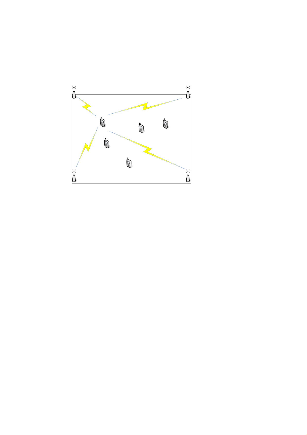
The CSL RTLS solution is based on the application of time of arrival technology.
In the RTLS, an anchor is the device installed in a known position inside a zone,
normally, at the corners of the zone. The moving tag inside the zone can measure the
range to each anchor so as to obtain its absolute position inside the zone.
Tag
A Zone
Anchor
AnchorAnchor
Anchor
In a minimum system, 4 anchors – 3 normal anchors CS5111LP and 1 master anchor
CS5113LP- are installed in a zone. However, the more the anchors are installed, the
higher the accuracy of the tag position to be obtained.
The accuracy of positioning is +/-1 meter.
3
Page 4
1 System Component Description
1.1 CS3151
1.1.1 Product Description
CS3151 is a battery-operated active RFID tag. Three AAA size primary batteries
( either alkaline or lithium/Iron Disulfide )or Ni-MH rechargeable batteries can be
installed for normal function.
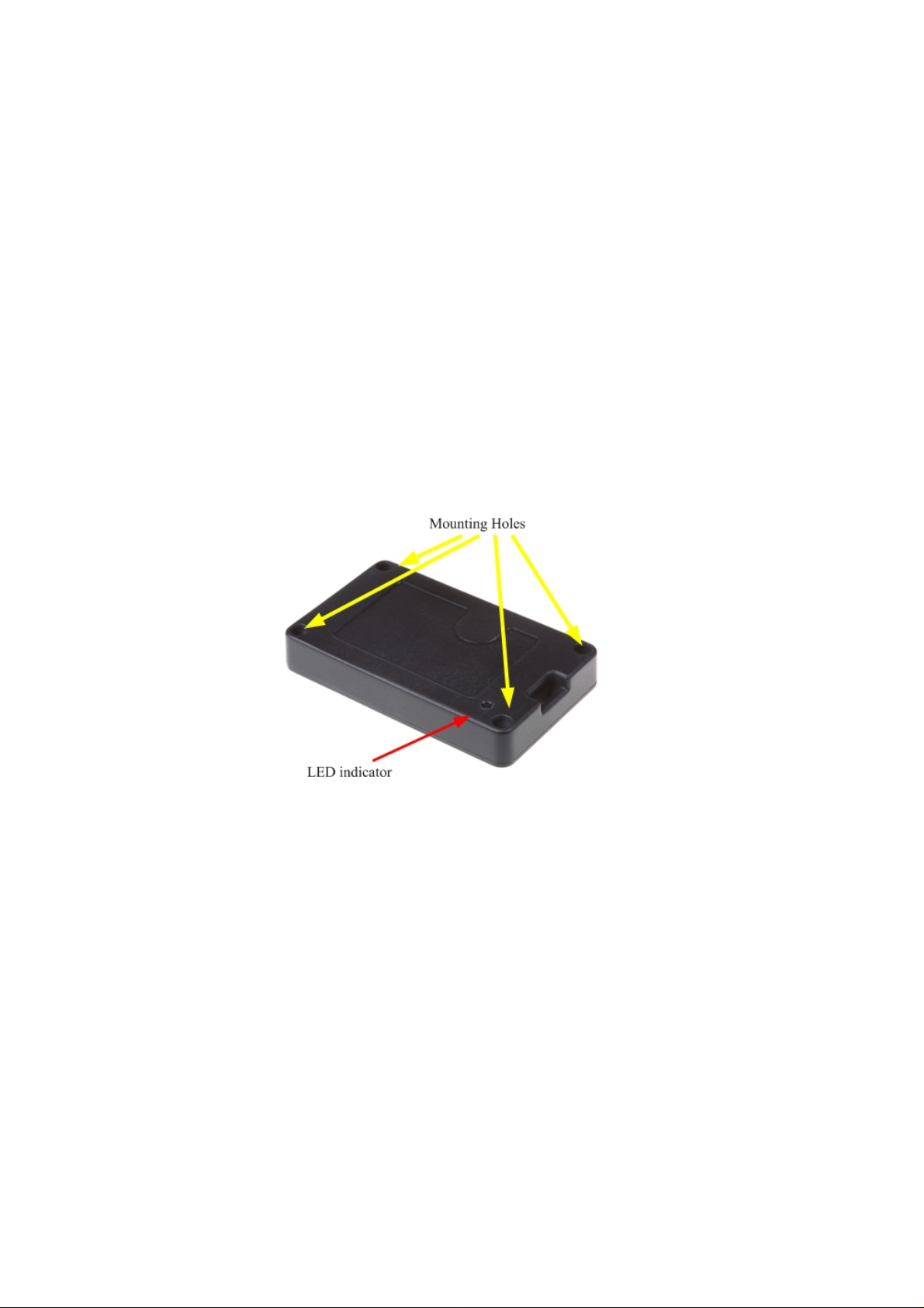
CS3151 are designed so that they can be attached to the tracking assets or simply
hanging on the moving objects, depending on the applications. There are four
holes on the corners of the tag housing that can allow the tag to be bolted firmly
on the asset. Both of the facets have light indicators so either face can be attached
to the asset.
1.1.2 Installation Procedure
When batteries are initially installed, CS3151 tags will be in listening mode.
In this mode, the CS3151 tags will listen to the commands from CS5113LP
master anchor for configuration.
Once configuration is completed, CS3151 is in the operating mode and ready
for RTLS tracking.
4
Page 5

1.1.3 Product Specification
1.1.4 Antenna Properties
CS3151 employs embedded miniaturized Omni-directional chip antenna for
effective RF transmission and reception. The antenna property is as below :
Electrical Items Specifications
Model 3030A5887-01
Type of antenna SMD chip type
Frequency range 2400MHz – 2500MHz
Nominal impedance 50 ohm
Polarization Linear
V.S.W.R 1.5 typically, mounting on CS3151
5
Page 6

Gain 2dBi typically, mounting on CS3151
Mechanical Items Specifications
Dimension in millimeter 12.8(L) x 3.9(W) x 1.1(H)
Weight 0.1gram
6
Page 7

1.2 CS5111LP
1.2.1 Product Description
CS5111LP is the RTLS anchor( or reader). It integrates the high gain 2.4GHz
ISM band antenna and the electronics PCB into one housing for robustness
and easy installation. CS5111LP is designed to be mounted at the back panel.
1.2.2 Installation Procedure
CS5111LP can be fed with DC voltage ranges from 12V to 34Vdc. The dc
plug is 2.5mm locked type. CS5111LP is fully programmed and ready for
normal operation once power is on. No extra configuration procedure is
required.
7
Page 8

1.2.3 Product Specifications
8
Page 9

1.3 CS5113LP
CS5113LP is the RTLS master anchor( or reader). It integrates the high gain
2.4GHz ISM band antenna and the electronics PCB into one housing for
robustness and easy installation. CS5113LP has Ethernet connectivity
function to communicate with the server application. CS5113LP is also a
POE PD that can allow it to be powered through IEEE 802.3 certified PSE.
CS5113LP can be fed with DC voltage ranges from 12V to 34Vdc. The dc
plug is 2.5mm locked type. Once powered on, CS5113LP is ready to
communicate with server through Ethernet port for configuration and RTLS
functions.
CS5113LP can also be powered by a IEEE802.3 certified PSE. When the
POE is in function, the DC adapter should be unplugged from the DC jack.
1.3.1 Product Description
1.3.2 Installation procedure
When connected to the server via Ethernet connection, Shielded-FTP
Ethernet cables should be used to for optimal performance.
9
Page 10

1.3.3 Product Specifications
10
Page 11

Federal Communication Commission Interference Statement
This equipment has been tested and found to comply with the limits for a Class B digit al device, pursuant to
Part 15 of the FCC Rules. These limits are designed to provide reasonable protection against harmful
interference in a residential installation. This equipment generates, uses and can radiate radio frequency
energy and, if not installed and used in accordance with the instructions, may cause harmful interference to
radio communications. However, there is no guarantee that interference will not occur in a particular
installation. If this equipment does cause harmful interference to radio or television reception, which can
be determined by turning the equipment off and on, the user is encouraged to t ry to correct the interference
by one of the following measures:
z Reorient or relocate the receiving antenna.
z Increase the separation between the equipment and receiver.
z Connect the equipment into an outlet on a circuit different from that to which the receiver is
connected.
z Consult the dealer or an experienced radio/TV technician for help.
FCC Caution: Any changes or modifications not expressly approved by the party responsible for
compliance could void the user's authority to operate this equipment.
This device complies with Part 15 of the FCC Rules. Operation is subject to the following two conditions: (1)
This device may not cause harmful interference, and (2) this device must accept any interference received,
including interference that may cause undesired operation.
This device and its antenna(s) must not be co-l ocated or ope rating in co njunction with any other antenna or
transmitter.
This product must be installed by a professional technician/installer.
 Loading...