

Page 1

User Manual of CSL RTLS System
CS3151BBCD Wrist Tag
CS3151TC Asset Tag
CS5111TD Reader
CS5112TD Reader
CS5113TD Reader with Ethernet Bridge
CS5114TD Reader with Ethernet Bridge
CS5116TD Reader
CS5118TD Reader with Ethernet Bridge
1
Page 2

Table of Content
User Manual of CSL RTLS System...............................................................................1
Introduction..................................................................................................................3
1 System Component Description..........................................................................4
1.1 CS3151BBCD............................................................................................4
1.1.1 Product Description .......................................................................4
1.1.2 Installation Procedure ....................................................................5
1.1.3 Product Specification.....................................................................6
1.1.4 Antenna Properties.........................................................................6
1.2 CS3151TC................................................................................................12
1.2.1 Product Description .....................................................................12
1.2.2 Installation Procedure ..................................................................12
1.2.3 Product Specification...................................................................13
1.2.4 Antenna Properties.......................................................................13
1.3 CS5111TD/CS5112TD ............................................................................15
1.3.1 Product Description .....................................................................15
1.3.2 Installation Procedure ..................................................................17
1.3.3 Product Specifications .................................................................18
1.3.3.1 CS5111TD Product Specifications ..............................................18
1.3.3.2 CS5112TD Product Specifications..............................................19
1.4 CS5113TD/CS5114TD ............................................................................20
1.4.1 Product Description .....................................................................20
1.4.2 Installation procedure...................................................................22
1.4.3 Product Specifications .................................................................23
1.4.3.1 CS5113TD Product Specifications..............................................23
1.4.3.2 CS5114TD Product Specifications..............................................24
1.5 CS5118/CS5116.......................................................................................25
1.5.1 Product Description .....................................................................25
1.5.2 Installation procedure...................................................................40
1.5.3 CS5118/CS5116 Product Specifications......................................41
1.5.3.1 CS5118 Product Specifications....................................................41
1.5.3.2 CS5116 Product Specifications....................................................42
2
Page 3

Introduction
The CSL RTLS solution is based on the application of time of arrival technology.
In the RTLS, an anchor is the device installed in a known position inside a zone,
normally, at the corners of the zone. The moving tag inside the zone can measure the
range to each anchor so as to obtain its absolute position inside the zone.
Tag
A Zone
Anchor
AnchorAnchor
Anchor
In a minimum system, 4 anchors – 3 slave anchors CS5111TD/CS5112TD and 1
master anchor CS5113TD/CS5114TD- are installed in a zone. However, the more the
anchors are installed, the higher the accuracy of the tag position to be obtained.
The accuracy of positioning is +/-1 meter.
3
Page 4

1 System Component Description
1.1 CS3151BBCD
1.1.1 Product Description
CS3151BBCD is a battery-operated active RFID tag. Rechargeable Lithium
Polymer batteries are installed for normal function. Charging interface is a 2-pin
charging contact. A charging cradle is required to mount CS3151BBCD on during
charging.
CS3151BBCD is designed so that they can be worn on the wrist of human body
to track the postion of the moving object. There is a button at the front panel of
the tag for various emergency applications. Light indicators are located on the
bottom side.
4
Page 5

1.1.2 Installation Procedure
Batteries are preinstalled in factory. When the batteries are recharged, or
when the tag is plugged into the charger, CS3151BBCD tag will be in
listening mode. In this mode, the CS3151BBCD tags will listen to the
beacons from CS5113LP master anchor and commence registration process.
Once registration is completed, CS3151BBCD is in the operating mode and
ready for RTLS tracking.
5
Page 6

diameter, 14mm
CSL RTLS Protocol, orderly inventory method to handle
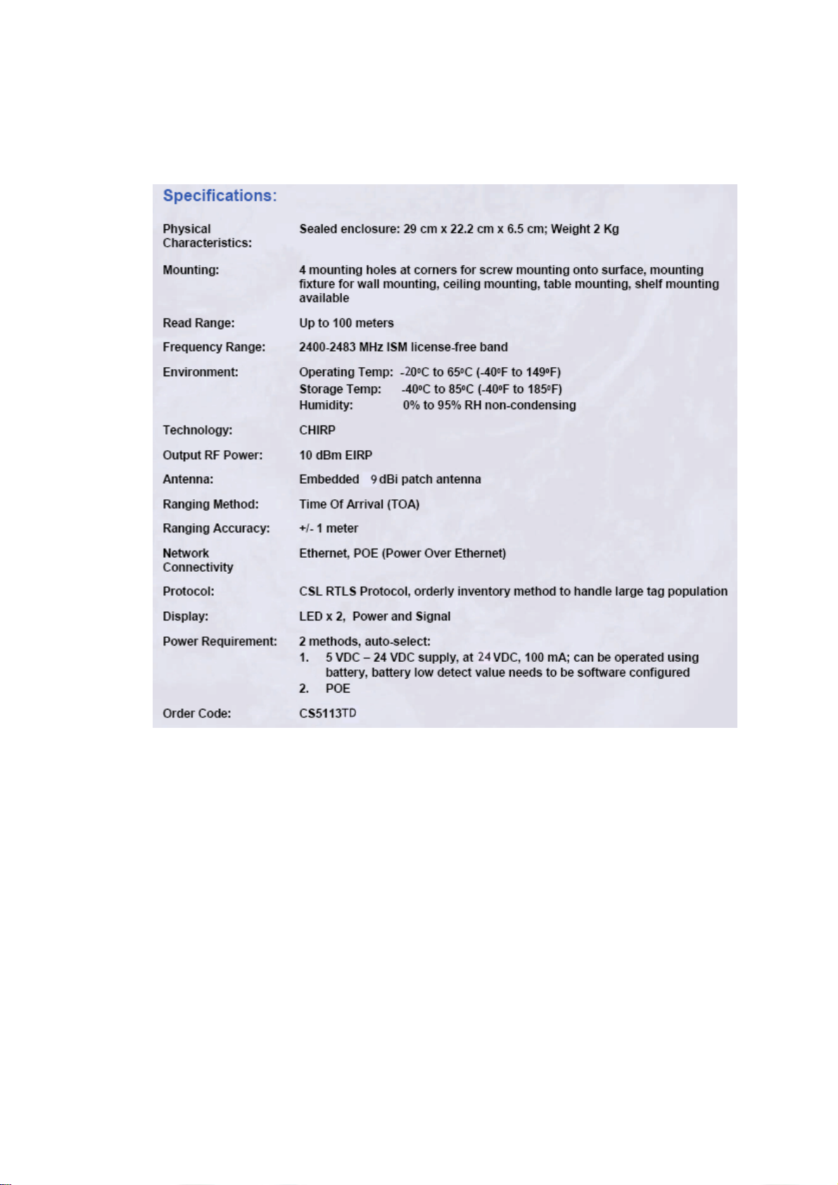
1.1.3 Product Specification
Specifications:
Physical
Characteristics:
Read Range: Up to 100 meters depending on reader power
Frequency: 2400-2483 MHz ISM license-free band
Environment:
Technology: CHIRP
Output RF Power:
Ranging Method: Time Of Arrival (TOA)
Ranging Accuracy:
Protocol:
Battery: Internal rechargeable Li Polymer battery
Order Code: CS3151BBCD
Plastic sealed enclosure: 52 mm
thickness; Weight 45 g (with wrist strap)
Operating Temp: -40°°°°C to 65°°°°C (-40°°°°F to 149°°°°F)
Storage Temp: -40°°°°C to 85°°°°C (-40°°°°F to 185°°°°F)
Humidity: 0% to 95% RH non-condensing
14 dBm EIRP +/-1.5dB
Best case up to +/- 1 meter
large tag population
1.1.4 Antenna Properties
CS3151BBCD employs two miniaturized SMD antennas for effective RF
transmission and reception. The antenna properties are as below :
Antenna 2 :
6
Page 7

7
Page 8

8
Page 9

9
Page 10
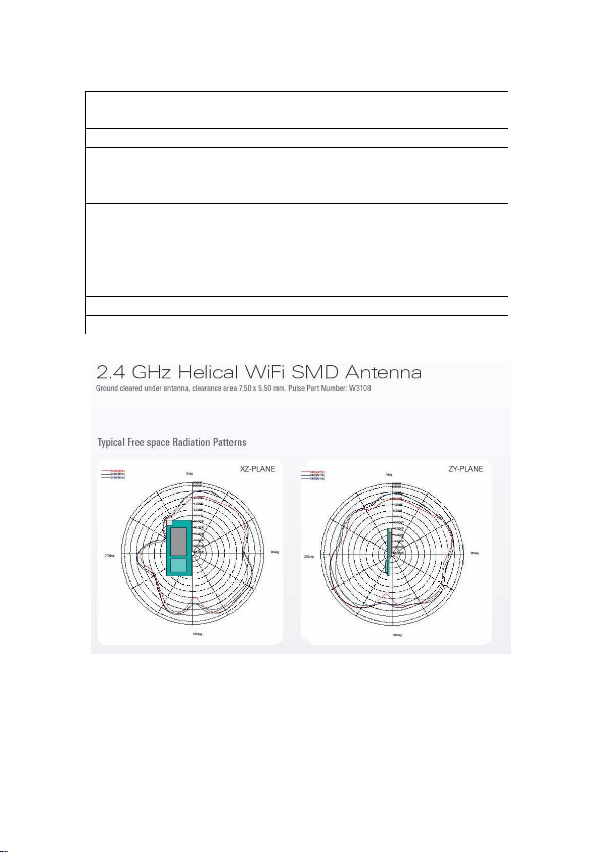
Antenna 1 :
Electrical Items Specifications
Model W3108
Type of antenna SMD type
Frequency range 2400MHz – 2500MHz
Nominal impedance 50 ohm
Polarization Linear
V.S.W.R 1.5 typically, mounting on CS3151BB2
Gain 1.5dBi typically, mounting on
CS3151BB2
Mechanical Items Specifications
Dimension in millimeter 5(W) x 2.5(L) x 5.5(H)
Weight 0.14gram
10
Page 11

11
Page 12
1.2 CS3151TC
1.2.1 Product Description
CS3151TC is a battery-operated active RTLS tag. Three AAA size primary
batteries ( either alkaline or lithium/Iron Disulfide )or Ni-MH rechargeable
batteries can be installed for normal function.
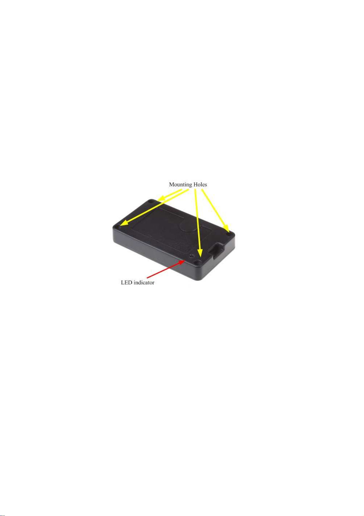
CS3151TC is designed so that it can be attached to the tracking assets or simply
hanging on the moving objects, depending on the applications. There are four
holes on the corners of the tag housing that can allow the tag to be bolted firmly
on the asset. Both of the facets have light indicators so either face can be attached
to the asset.
1.2.2 Installation Procedure
When batteries are initially installed, CS3151TC tags will be in listening
mode. In this mode, the CS3151TC tags will listen to the commands from
CS5113TD/CS5114TD master anchor for configuration.
Once configuration is completed, CS3151TC is in the operating mode and
ready for RTLS tracking.
12
Page 13

;
CSL RTLS Protocol, orderly inventory method to handle
1.2.3 Product Specification
Specifications:
Physical
Characteristics:
Read Range: Up to 100 meters depending on reader power
Frequency: 2400-2483 MHz ISM license-free band
Environment:
Technology: Digital Modulation
Output RF Power:
Ranging Method: Time Of Arrival (TOA)
Ranging Accuracy:
Protocol:
Battery: AAA battery 3 pieces
Order Code: CS3151TC
Plastic sealed enclosure: 94 mm x 56 mm x 15 mm
Weight 84 g
Operating Temp: -40°°°°C to 65°°°°C (-40°°°°F to 149°°°°F)
Storage Temp: -40°°°°C to 85°°°°C (-40°°°°F to 185°°°°F)
Humidity: 0% to 95% RH non-condensing
+10 dBm EIRP
+/- 1 meter
large tag population
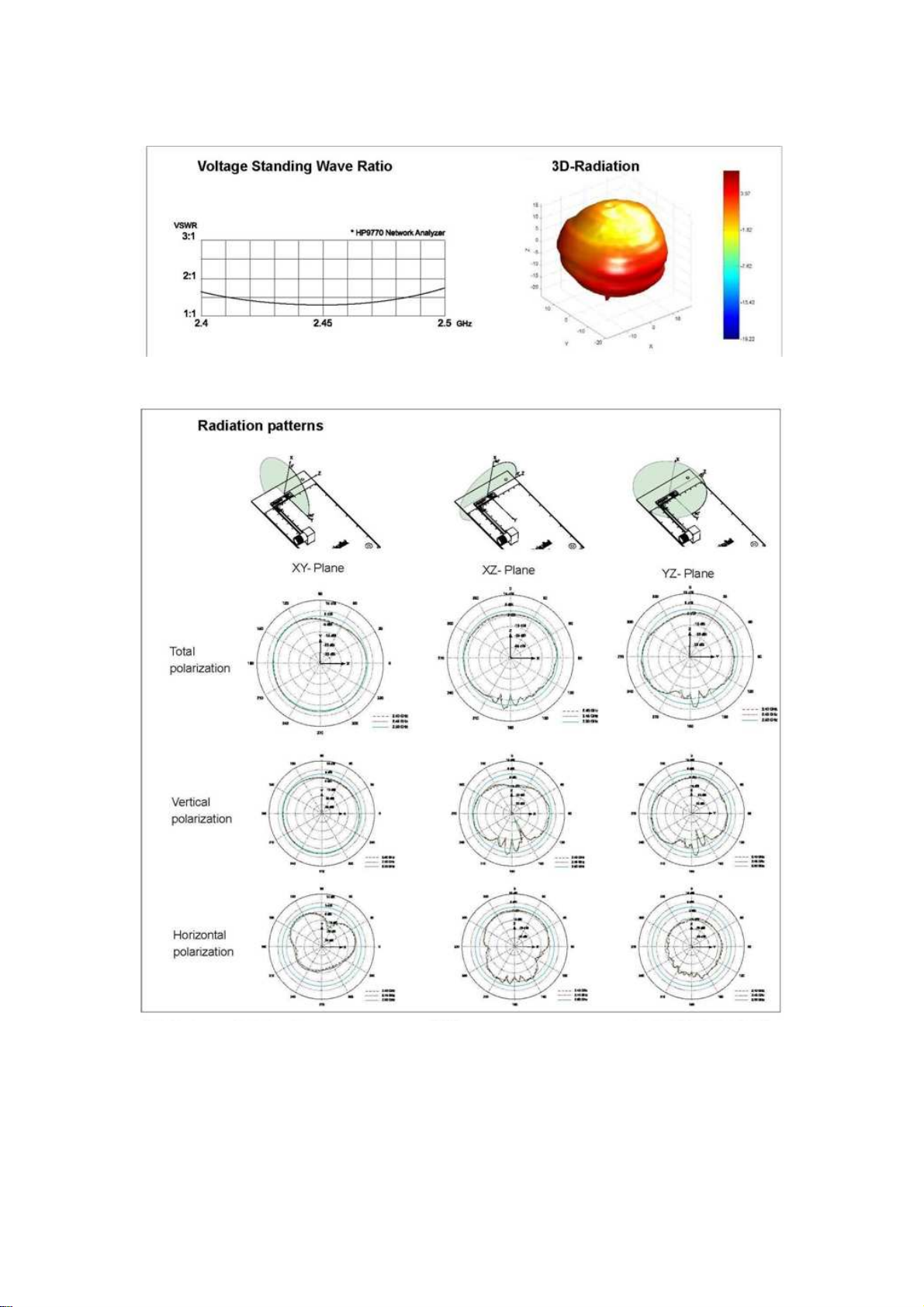
1.2.4 Antenna Properties
CS3151TC employs a miniaturized SMD antenna for effective RF
transmission and reception. The antenna properties is as below :
Electrical Items Specifications
Model 3030A5887-01
Type of antenna SMD chip type
Frequency range 2400MHz – 2500MHz
Nominal impedance 50 ohm
Polarization Linear
V.S.W.R 1.5 typically, mounting on CS3151TC
Gain 2dBi typically, mounting on CS3151TC
Mechanical Items Specifications
Dimension in millimeter 12.8(L) x 3.9(W) x 1.1(H)
Weight 0.1gram
13
Page 14
14
Page 15

1.3 CS5111TD/CS5112TD
1.3.1 Product Description
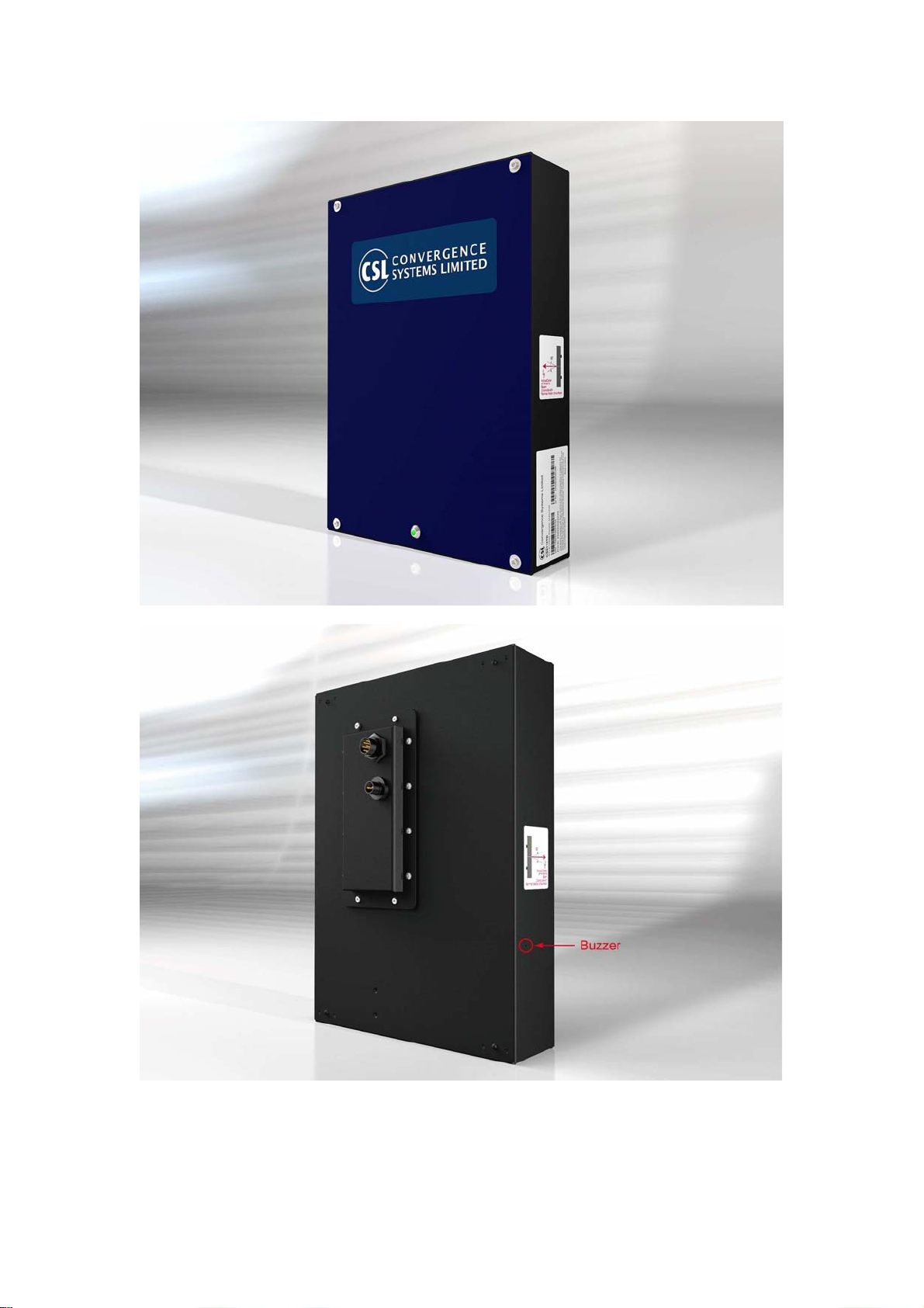
CS5111TD/CS5112TD are the RTLS anchor( or reader). The high gain
2.4GHz ISM band antenna and the electronics PCB are integrated into one
housing for robustness and easy installation. CS5111TD/CS5112TD are
designed to be mounted at the back panel.
15
Page 16
16
Page 17

1.3.2 Installation Procedure
CS5111TD/CS5112TD can be fed with DC voltage ranges from +12Vdc to
+24Vdc. The dc plug is 2.5mm locked type. CS5111TD/CS5112TD are fully
programmed and ready for normal operation once power is on. No extra
configuration procedure is required.
17
Page 18

1.3.3 Product Specifications
1.3.3.1 CS5111TD Product Specifications
18
Page 19

1.3.3.2 CS5112TD Product Specifications
19
Page 20

1.4 CS5113TD/CS5114TD
1.4.1 Product Description
CS5113TD/CS5114TD is the RTLS master anchor( or reader). It integrates
the high gain 2.4GHz ISM band antenna and the electronics PCB into one
housing for robustness and easy installation. CS5113TD/CS5114TD has
Ethernet connectivity function to communicate with the server application.
CS5113TD/CS5114TD is also a POE PD that can allow it to be powered
through IEEE 802.3 certified PSE.
20
Page 21

21
Page 22

1.4.2 Installation procedure
CS5113TD/CS5114TD can be fed with DC voltage ranges from +12V to
+24Vdc. The dc plug is water-proof locked type.. Once powered on,
CS5113TD/CS5114TD is ready to communicate with server through
Ethernet port for configuration and RTLS functions.
CS5113TD/CS5114TD can also be powered by a IEEE802.3 certified PSE.
When the POE is in function, the DC adapter can be unplugged from the DC
jack.
When connected to the server via Ethernet connection, Shielded-FTP
Ethernet cables should be used to for optimal performance.
22
Page 23
1.4.3 Product Specifications
1.4.3.1 CS5113TD Product Specifications
23
Page 24

1.4.3.2 CS5114TD Product Specifications
24
Page 25

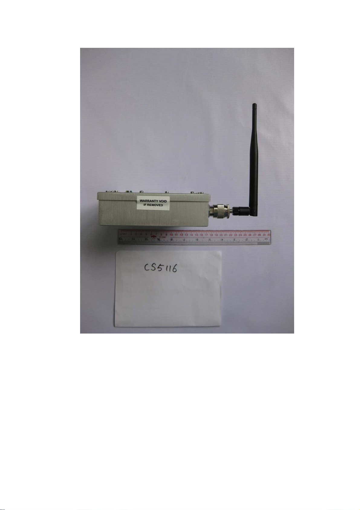
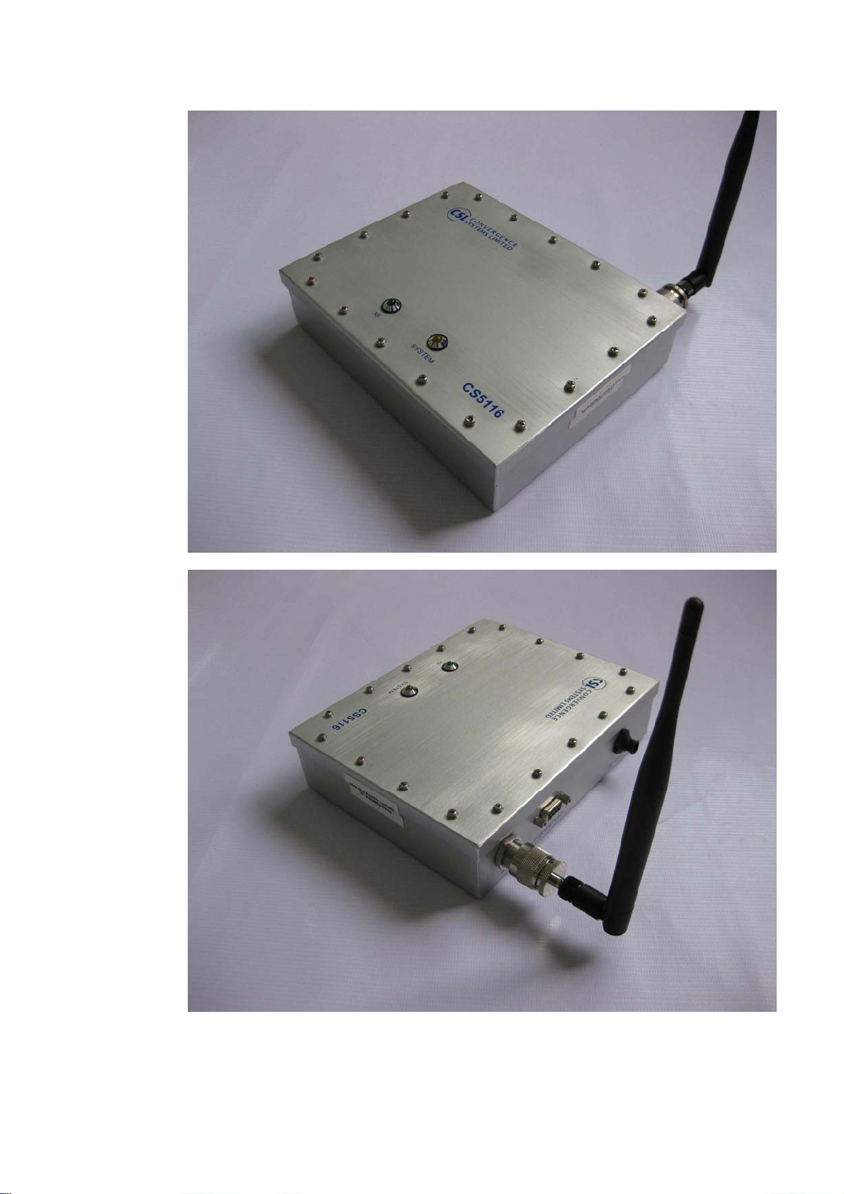
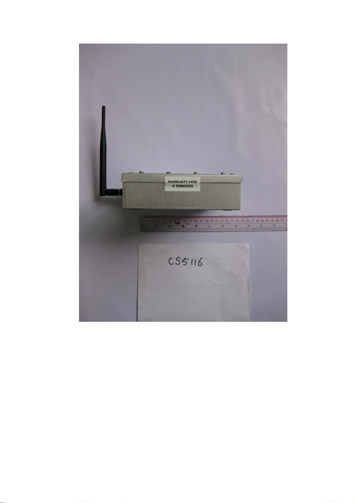
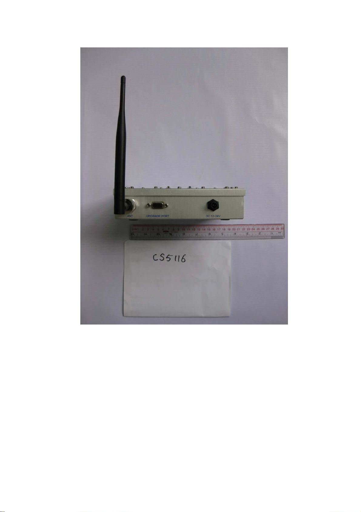
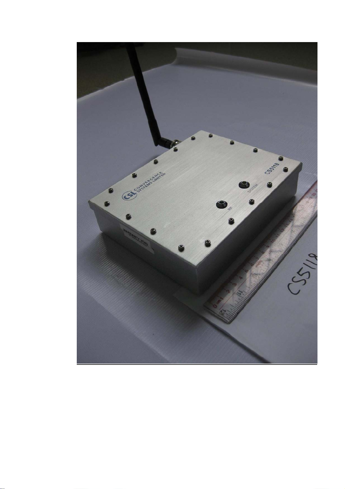
1.5 CS5118/CS5116
1.5.1 Product Description
CS5118 and CS5116 are the equivalence of CS5113TD/CS5114TD and
CS5111TD/CS5112TD, with the antenna replaced by omni-directional dipole
antennas. CS5118 has Ethernet connectivity function to communicate with
the server application. CS5118 is also a POE PD that can allow it to be
powered through IEEE 802.3 certified PSE.
CS5115 Outlook:
25
Page 26
26
Page 27

27
Page 28

28
Page 29

29
Page 30
30
Page 31
31
Page 32
32
Page 33

CS5118 Outlook:
33
Page 34

34
Page 35

35
Page 36

36
Page 37
37
Page 38

38
Page 39

39
Page 40

1.5.2 Installation procedure
CS5118/CS5116 can be fed with DC voltage ranges from 5V to 24Vdc. The
dc plug is water-proof locked type. The Ethernet connection on CS5118 is
also water-proof locked type. Once powered on, CS5118/CS5116 is ready to
communicate with server through Ethernet port for configuration and RTLS
functions. When connected to the server via Ethernet connection,
Shielded-FTP Ethernet cables should be used to for optimal performance.
40
Page 41

1.5.3 CS5118/CS5116 Product Specifications
1.5.3.1 CS5118 Product Specifications
41
Page 42

1.5.3.2 CS5116 Product Specifications
42
Page 43

Federal Communications Commission Interference
Statement
This equipment has been tested and found to comply with the limits for a Class B digital device, pursuant
to Part 15 of the FCC Rules. These limits are designed to provide reasonable protection against harmful
interference in a residential installation. This equipment generates, uses and can radiate radio
frequency energy and, if not installed and used in accordance with the instructions, may cause harmful
interference to radio communications. However, there is no guarantee that interference will not occur in
a particular installation. If this equipment does cause harmful interference to radio or television
reception, which can be determined by turning the equipment off and on, the user is encouraged to try to
correct the interference by one of the following measures:
Reorient or relocate the receiving antenna.
Increase the separation between the equipment and receiver.
Connect the equipment into an outlet on a circuit different from that to which the receiver is
connected.
Consult the dealer or an experienced radio/TV technician for help.
FCC Caution: Any changes or modifications not expressly approved by the party responsible for
compliance could void the user's authority to operate this equipment.
This device complies with Part 15 of the FCC Rules.
Operation is subject to the following two conditions: (1) This device may not cause harmful interference,
and (2) this device must accept any interference received, including interference that may cause
undesired operation.
This device and its antenna(s) must not be co-located or operating in conjunction with any other antenna
or transmitter.
This Class [B] digital apparatus complies with Canadian ICES-003.
Cet appareil numérique de la classe [B] est conforme à la norme NMB-003 du Canada.
43
 Loading...