

Page 1
Installation,
Operating Instructions &
Warranty Registration
IMPORTANT : to be read and kept by the user
APERO
7359 BB
421AA2439.A00
Page 2
2.
Planning the installation
2
Dear owner,
- Congratulations on the purchase of this new premium electric heater from
CONVECTAIR, manufacturer of the highest quality heating product in the
electrical industry.
- To obtain the best results and the ultimate in performance and comfort please
carefully read the installation and maintenance instructions shown in this
manual.
Introduction
1
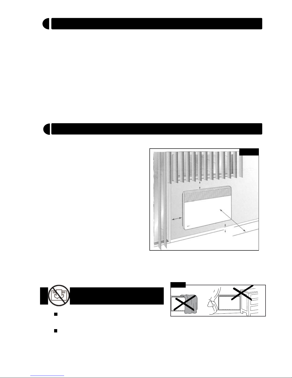
Choose the location where the
CONVECTAIR will be installed.
Check that nothing such as
drapes or furniture interferes
with the airflow to and from the
CONVECTAIR ; see required
clearances (Figure 1).
Make a note of the minimum
required clearances for this
heater and ensure that there are
no restrictions before choosing
the location.(see Figure 1).
6
"
150 mm
4
"
-
100 mm
20
"
520 mm
4
"
-
100 mm min.
MINIMUM
CLEARANCE
Figure 1
Do not cover or obstruct the air intake or outlet on the unit as this could
cause overheating and damage the heater.
IMPORTANT :
DO NOT COVER THE HEATER
The above logo warns of a risk : do
not cover.
Figure 2
1-
2-
3-
Page 3
Installation
3
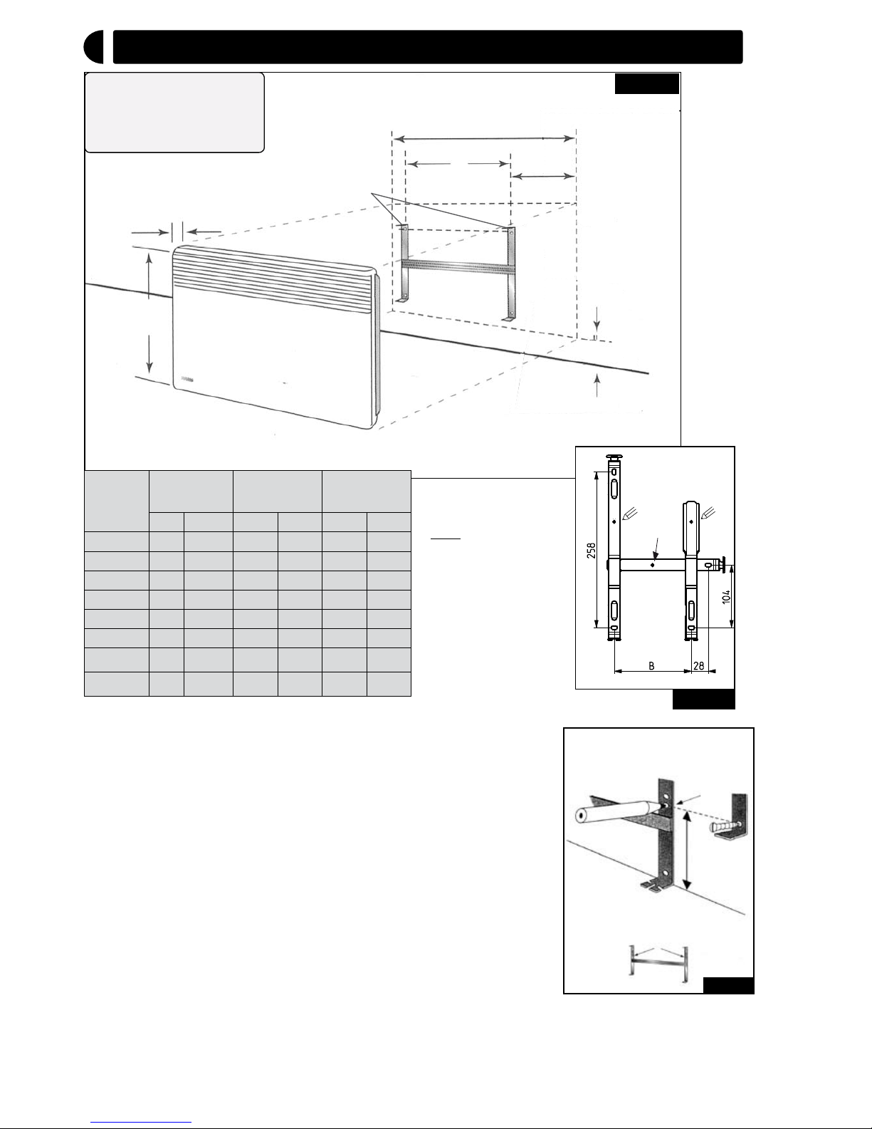
Note : to locate the
midpoint of the hea-
ter, use the hole (see
«2» in Fig. 3b).
3 1/8
"
80 mm
17
1/2
"
440 mm
4
"
100 mm
min.
Heater Width
B
Figure 3a
UTILISATION DU DOSSERET
COMME GABARIT DE MARQUAGE
DOSSERET
REPÈRE
A
REPÈRE
A
CRAYON
7 1/8"
180 mm
Figure 3c
28
B
104
258
2
A
A
500=>1250W
Figure 3b
WATTS
Largeur
Appareil
B C
mm po mm po mm po
500 340 13 3/8
128 5 106
4 1/8
750 340 13 3/8
128 5 106
4 1/8
1000 420 16 1/2
208
8 1/4
106
4 1/8
1250 500 19 5/8
208
8 1/4
146
5 3/4
1500 580 22 7/8
178 7 201
7 7/8
1750 660 26
248
9 3/4
206
8 1/8
2000 740 29 1/8
320
12 5/8
210
8 1/4
2KW/208V 820 32 1/4
405 16 207
8 1/8
1
C
1- Free mounting bracket by pressing and pulling both
locking brackets.
2- Use the mounting bracket as a template by holding it
against the wall flush to the floor. Use the hole shown on
fig. 3b to locate the bottom fasteners. With the template
the unit will be installed at 6 ” (15 cm) from the floor
(Figure 3a & 3b). Note that the minimum installation
height is 4” (10cm).
3- Relocate the mounting bracket to match the marks
with the holes for the bottom fasteners.
4- Check horizontality of the mounting bracket then
mark and pierce the 4 holes for fastening.
5- Replace mounting bracket and fasten it with screws
3 conductor wiring should be
used if you are planning to use
this unit with the CONVECTAIR
Programmer (see Technical
Sheet).
3.
Page 4
4.
Electrical Connection
4
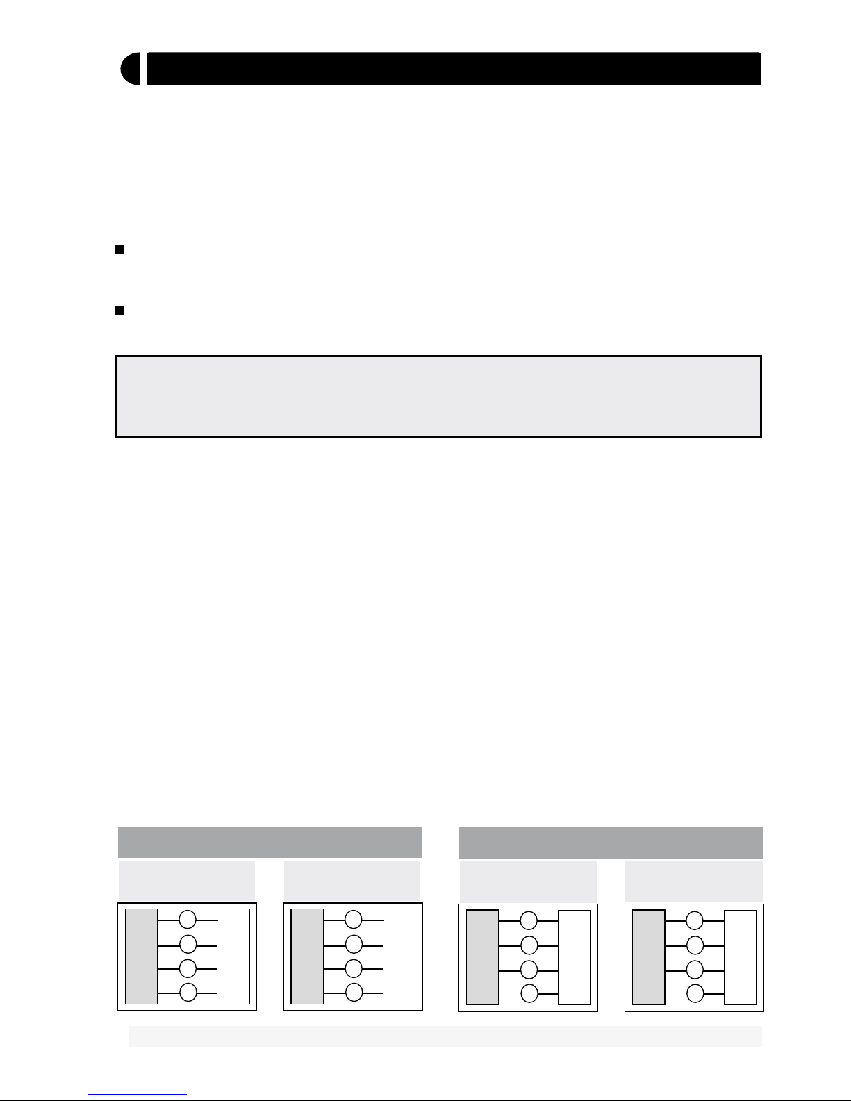
The unit must be hooked up with the rectangular junction box already installed in
the wall.
1- Connect the ground wire (C) to the green wire (G) inside the connection box.
2- Connect the black (B) and red (R) leads from the heater to the electrical supply
wires (see diagrams below).
3- You will find, on the supply cord, a fourth purple wire (PW) with a sealed end.
This wire must not be used for the electrical connection.This wire will be used
only if the unit is connected to a CONVECTAIR "Programmer" central control
system.
4- Carefully put back all wires inside the box, close and screw the cover.
5- Hook the CONVECTAIR unit onto the mounting bracket tabs with the unit
slightly angled towards you. Push the CONVECTAIR towards the wall until it is
engaged on both locking brackets.
CAUTION : This unit must be connected to a 240 volts or 208 volts circuit,
60 cycles. Disconnect power supply before making wiring connections to
prevent electrical shock or equipment damage.
CONVECTAIR recommends that this heater be installed in accordance with
national and local codes.
- A rectangular junction box must be installed in the wall, prior to electrical hookup
(Figure 3a). The box must be of appropriate size to receive the necessary electrical
connections and the 2 3/4’’ x 4 1/2’’ (70mmx115mm) cover that is supplied with
the unit cable.
To prevent short circuits and electrical shocks turn the power off at the main
panel before attempting the installation or any repairs.
If the power cable is damaged it must be replaced by the manufacturer, an
approved service depot or a technician with similar qualifications.
R
PW
R
HEATER
B
B
G
POWER LINE
CANADA
C
PW
WITHOUT using a pilot wire (PW).
CANADA
U.S.A.
B- Black G - Green R - Red W - White C - Copper PW - Pilote Wire
R
PW
R
HEATER
B
B
G
POWER LINE
C
R
PW
W
B
B
G
POWER LINE
C
U.S.A.
R
PW
W
HEATER
B
B
G
POWER LINE
C
PW
WITH the use of a pilot wire (PW).
Page 5
How to use your heater
5
CONVECTAIR heaters operate in short cycles. The red indicator light
tells you when heat is on. The CONVECTAIR will always remain warm
and ambient temperature will remain constant. It is normal in very cold
temperatures for the unit to become hot. Caution is advised when young
children are present.
5.
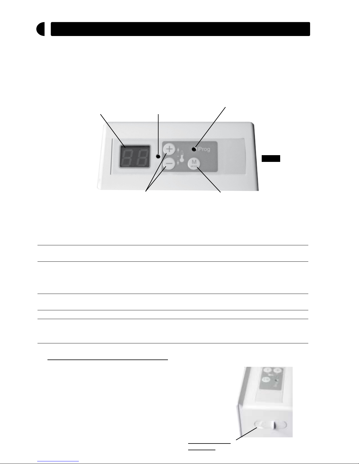
Temperature and heating
mode display
Heating indicator
Temperature setting keys
Mode selection key
Programmer mode indicator
Figure 4
The following 5 settings can accessed with the Mode selection key :
COMFORT Shows the temperature
setting
The heater maintains the desired comfort
temperature.
ECONOMY EC The temperature is lowered to the desired
setting without changing the comfort setting
(night setback, unused rooms, temporary absence.
FROST PROTECTION HG The temperature is set at 45°F (7°C) for long
term absence.
STAMDBY (NO HEAT) - - The heater stops heating
PROGRAMMER Any of the above,
with the Programmer
indicator light on.
Allows the heater to respond to signals sent
by a Programmer (CONVECTAIR 7392,
sold separately).
Turning the power
ON or OFF
Place the sliding switch located on the right side
of the thermostat to “1” position to turn the heater
ON.
To turn the heater completely OFF, place the switch
in the “0” position.
1- Turning the power ON or OFF :
Page 6
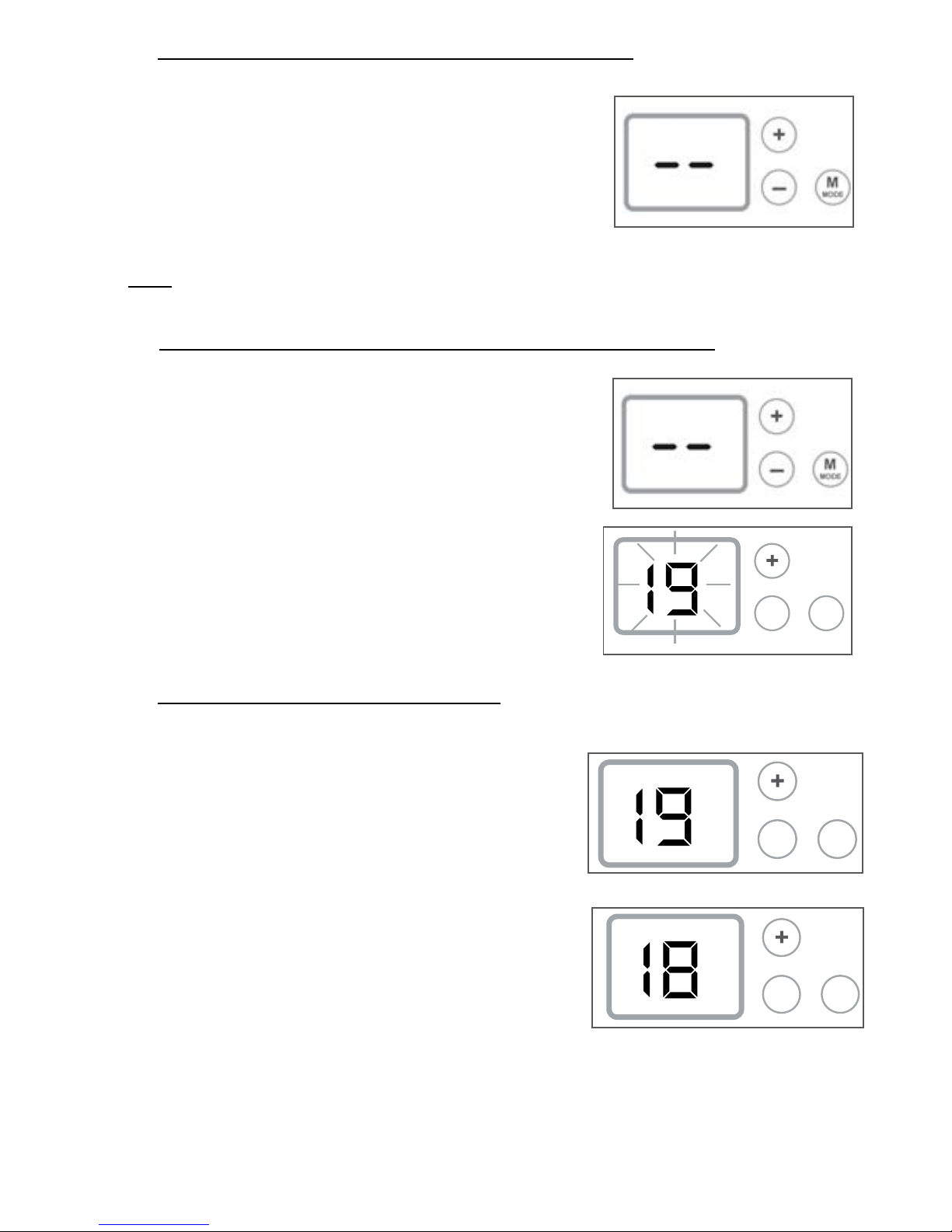
2- Turning the thermostat ON or OFF (standby) :
Note : current temperature settings are kept in memory.
4- Setting the desired temperature :
To start the heater press the Mode key once. The
display will show the current thermostat setting
(factory default is 19°C).
To place the heater on Standby (no heat), press the
Mode key repeatedly until the display shows “--”.
6.
3- Displaying the temperature in Fahrenheit or Celsius :
Prog
-
M
MODE
-
M
MODE
-
M
MODE
-
M
MODE
-
M
MODE
-
M
MODE
VECTORISE
--
Prog
-
M
MODE
-
M
MODE
-
M
MODE
-
M
MODE
-
M
MODE
-
M
MODE
-
M
MODE
-
M
MODE
VECTORISE
--
Prog
-
M
MODE
-
M
MODE
-
M
MODE
-
M
MODE
-
M
MODE
With the power ON, and the Mode selector on
Standby (“--”), press the Mode and + keys at the
same time and hold for 3 seconds.
The display flashes the temperature in the new
scale and reverts to Standby (“--”).
Press the Mode key to display the temperature in
the new scale.
Turn the heating on. The display shows 19.0°C
(or 66.0°F if set in Fahrenheit). Using the + and
– keys, you can raise or lower the setting as you
wish by 1° each time the key is pressed.
This is how you can adjust the thermostat to your
desired temperature (see example).
To confirm this comfort level, you may follow the
following procedure, preferably in the evening
(no sun influence) : close the doors to the room
where the heater is located ; wait about one hour
to allow for the temperature to stabilize, then
adjust the setting up or down (+ or – keys) until
the temperature feels right.
Allow another hour to verify that the temperature
has stabilized at the correct level.
Page 7
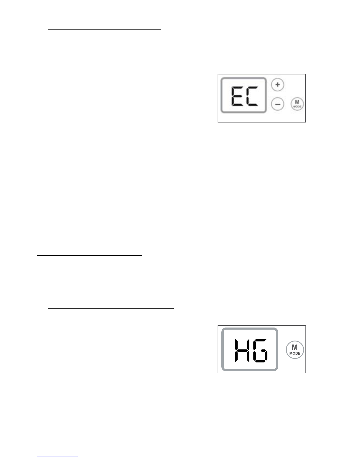
5- SETBACk (ECONOMY) MODE :
When the heater is in EC Mode, it will maintain the temperature at a lower value.
This setting is useful to reduce energy consumption at night or when a room is
temporarily unused.
To select the EC mode :
Press the Mode key briefly until the letters EC appears
on the display.
To display the EC temperature setting :
While in EC mode, press the + or – key. The EC
temperature setting will appear on the display (the
default setting is 3°C or 5°F below the Comfort
temperature).
6- FROST PROTECTION MODE : HG :
In case of longer term absence (24hrs or more), the
HG mode will maintain the room temperature at 7°C
(45°F). You can reduce your energy consumption
while maintaining a minimum safe temperature.
To select the HG mode :
Press the Mode key until the display shows : HG.
7.
To change the EC temperature :
When the display is in Ec mode, press and maintain the Mode key until
the temperature value starts to blink. Release the Mode key and adjust the
temperature up or down in 1° steps using the + or – keys. Press Mode to
confirm the setting.
Note : the EC temperature is relative to the Comfort temperature. If the
Comfort setting is changed, the EC temperature will change automatically
to maintain the same difference between the two values.
Exceptions to the EC Mode :
if the heater is connected to a Programming system, it will still respond to a
Frost Protection instruction.
Page 8
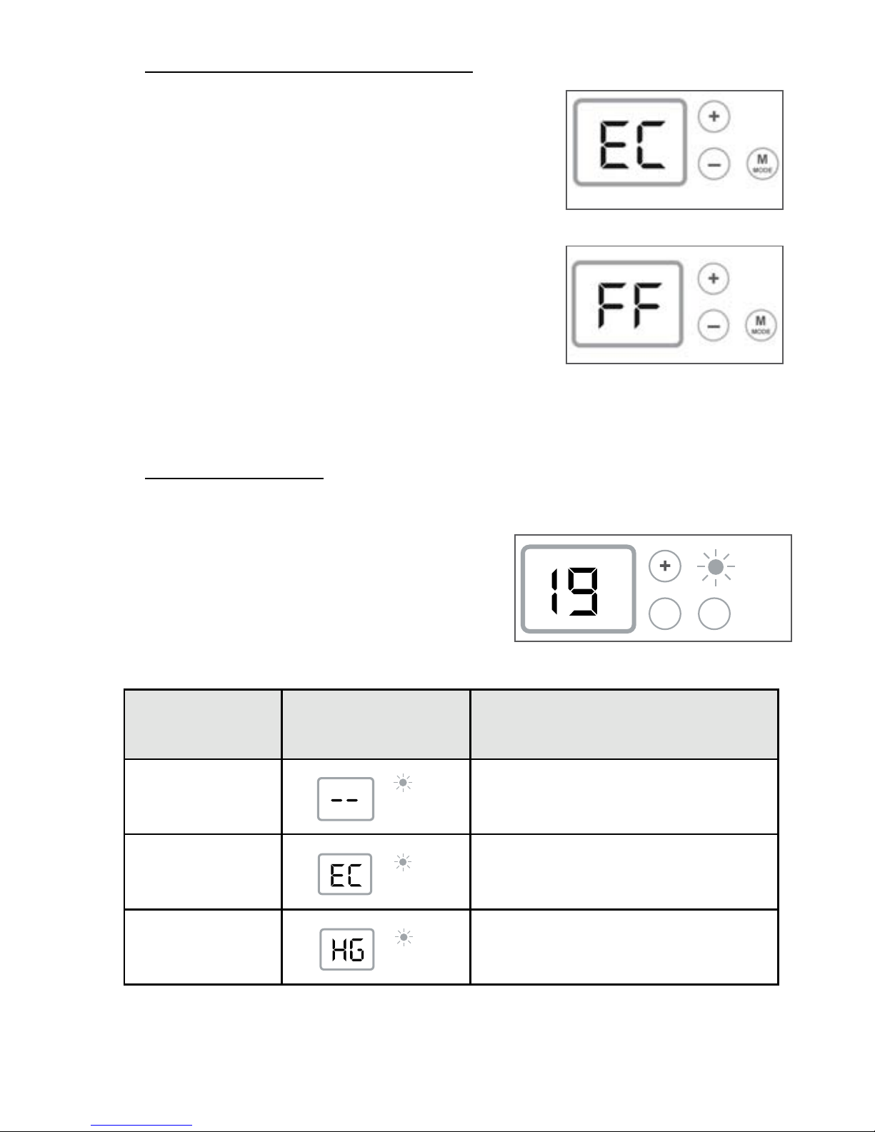
This mode allows the heater to respond to
instructions from a central Programmer system
or from an individual Programmer module.
The thermostat display will show what instruction
is being received (see summary table below).
8- PROGRAM MODE
Programmer
signal
Display Heater operation
Heat OFF
Heater goes on standby (no heat)
Setback
Temperature is lowered by 3°C (5°F)
from the comfort setting (or as selected).
Frost protection
Maintains the room temperature at 7°C
(45°F).
-
M
MODE
VECTORISE
--
Prog
-
M
MODE
-
M
MODE
-
M
MODE
-
M
MODE
-
M
MODE
-
M
MODE
-
M
MODE
-
M
MODE
Prog
Prog
Prog
-
M
MODE
-
M
MODE
Prog
-
M
MODE
-
M
MODE
-
M
MODE
-
M
MODE
Prog
-
M
MODE
Prog
-
M
MODE
-
M
MODE
-
M
MODE
-
M
MODE
Prog
Prog
-
M
MODE
8.
-
M
MODE
VECTORISE
--
Prog
-
M
MODE
-
M
MODE
-
M
MODE
-
M
MODE
-
M
MODE
-
M
MODE
-
M
MODE
-
M
MODE
Prog
-
M
MODE
7- LOCkING THE HEATER CONTROLS :
The control pad can be locked from any Mode
selection to prevent tampering.
To lock the control : From any Mode setting, press
both the + and the – key at the same time and hold
for about 3 seconds. The display will blink to show
that the keyboard is locked.
Pressing any key when the keyboard is locked will
cause the screen to display «FF» and the heater will
not respond.
To unlock the keyboard, repeat the same procedure
:
press and hold both + and – keys at the same
time for about 3 seconds.
Page 9
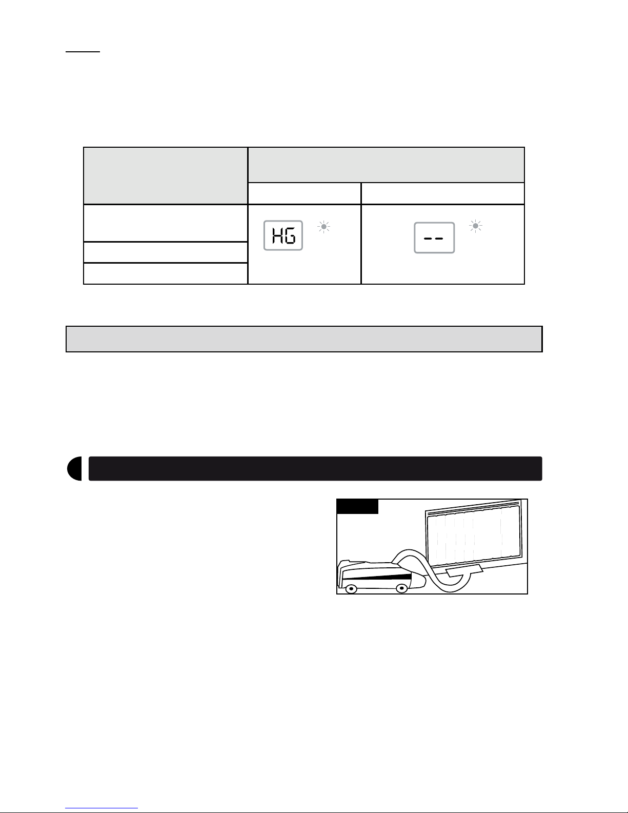
Note :
Frost Protection instructions from a Programming system will override all other
settings even if a heater is not set in the Program Mode.
In that case, the heater screen will display the appropriate symbol (see table
above) but the Programmer indicator light will be flashing.
Current Mode
SIGNAL FROM PROGRAMMER OR
OTHER CENTRAL PROGRAMMING SYSTEM
Frost protection Standby (no heat)
19 - Comfort
(temperature is displayed)
EC
HG
Prog
-
M
MODE
-
M
MODE
-
M
MODE
-
M
MODE
Prog
Prog
-
M
MODE
-
M
MODE
VECTORISE
--
Prog
-
M
MODE
-
M
MODE
-
M
MODE
-
M
MODE
-
M
MODE
-
M
MODE
-
M
MODE
-
M
MODE
Prog
Prog
Prog
-
M
MODE
-
M
MODE
9.
Temperature limiting control :
This heater is equipped with a manual reset control. In case of a malfunction of
the unit (blocked air output or intake, for example) the heater will stop heating
automatically. After correcting the malfunction the heater can be reset. To restart
the heater, push the button on the upper back panel of the heater.
Maintenance
6
To keep your CONVECTAIR unit clean,
regular maintenance is suggested. To remove
dust, use a soft cloth. To remove a stain, use
a damp cloth. For a better performance and
a maximum efficiency, it is suggested that
dust and lint be regularly removed from the
protective grille situated at the base of your
Convectair (Figure 6).
Figure 6
never use abrasive or aceTone-based producTs To clean
The heaTer as This may cause deTerioraTion of The epoxy
finish.
any repair on your convecTair heaTer should only be done
by a qualified Technician afTer disconnecTing The heaTer.
Page 10
10.
Operation and Maintenance TIPS
Your CONVECTAIR heater will become hot when in use. Caution is advised when
young children are present.
Do not insert small objects through the front louvers : this could cause electrical shortcircuit, fire or damage to the inner components.
Any use or modifications not approved by CONVECTAIR may cause electrical shortcircuits, fire or injuries to the users.
In certain cases, it is possible for yellowing of the grille to occur over time. This is
not due to a manufacturing defect. This is caused by surrounding air, which contains
smoke or dust, being heated and released through grille.
Prevention : it is suggested that grilles be frequently cleaned especially
with units installed in locations where cigarette smoke is present or in the
kitchen. Never use this heater during construction work or other activities
that generate a lot of dust.
Note : The first time your CONVECTAIR heats, a light smoke could be
released. This is normal and should disappear after about 2 to 3 minutes.
Diagnostics
7
IF YOUR CONVECTAIR DOES NOT HEAT :
Before calling your electrician, please go through these simple checks:
1- Make sure the breaker in the distribution panel is in the "ON" position.
2- Check that the function selector switch is on . Turn the setting dial to
position 9.
3- Check the overheat protection : first remove any obstruction from the inlet
and outlet grilles ; then reset the overheat button (see : Temperature limiting
controls).
4- If the light is still off, and no heat is generated, call your electrician or the
nearest CONVECTAIR repair center.
Page 11
11.
Warranty
8
30 Carré Sicard, Sainte-Thérèse QC, Canada J7E 3X6
Phone : 1-800-463-6478 Fax : (450) 434-3166
Email : [email protected]
www.convectair.com
2 years against all defects
5 years on heating element
All CONVECTAIR units are subject to a double warranty: 2 years on all parts and
manufacturing defects and 5 years on the heating element itself.
Warranty is applicable from date of purchase by the customer and under certain
specific conditions. All details furnished with each unit. Please keep your invoice
(purchase and/or installation).
REPAIR CENTERS :
Contact CONVECTAIR for information regarding your closest repair
center.
Toll-free :
1-800-463-6478
 Loading...