

Page 1
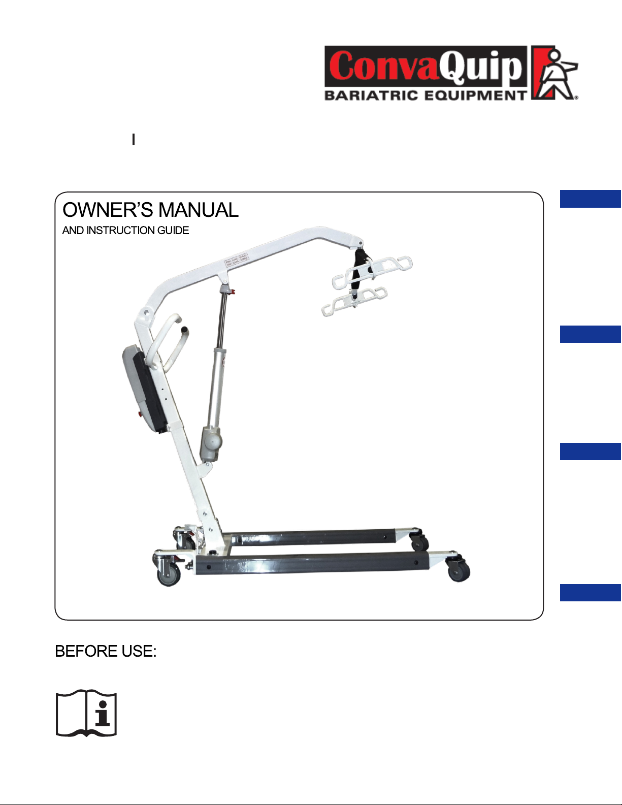
ConvaLift
F U L L B O D Y P A T I E N T L I F T
MODELS
ConvaLift CL600E
ConvaLift CL600E-D
ConvaLift
FEATURES
PRODUCT
ASSEMBLY WARRANTY
Made in China
Ensure the product has been assembled according to the
instructions in this manual.
All operators should have received or read and understood the
instructions for safe and proper operation of the patient lift.
INSTRUCTIONS
OPERATING
*ConvaQuip CL600E shown
Page 2

Thank you for choosing ConvaQuip!
To better serve you, please record
the following information:
Supplier Name:
Telephone:
Serial #:
Date of Purchase:
INSPECT YOUR MERCHANDISE
Upon receipt of your ConvaLift, verify that all merchandise is complete and free from
any shipping damage. Refuse delivery if the packaging appears to be badly damaged.
If the merchandise is received damaged or is missing components, contact the shipping
company immediately and file a claim.
For further assistance, contact your local dealer or ConvaQuip at the following:
ConvaQuip Ind., Inc.
P.O. Box 3417
Abilene, TX 79604
325-677-4177 / Toll Free 800-637-8436
www.ConvaQuip.com
ConvaQuip ®
REV 1.0 7.17.14
Page 3

SAFETY INSTRUCTIONS
The ConvaQuip Series of full body patient lifts reflect innovative state
of the art design to increase user mobility. The ConvaLift will provide
years of service if it is properly maintained as any electric and/or
mechanical equipment requires. Please pay careful attention to the
following important information regarding the care, maintenance, and
operation of the patient lift. Carefully read these instructions before
assembling the lifter, or attempting to lift a user with the device.
PLEASE NOTE THE FOLLOWING:
• Special care must be taken with users/patients who cannot themselves provide
assistance while being lifted. (i.e. patients who are comatose, spastic, agitated, or
otherwise severely handicapped.)
• The patient lift should be used solely for transferring a user/patient from one
utility (beds, chairs, toilets, etc.) to another. The patient lift should not be used for
transporting or moving any patient from one location to another location.
• During lifting or lowering, whenever possible, always keep the base of the lift in the
widest position.
• The base of the lift should be closed before moving the lift.
• Do not roll casters over any object while the user/patient is in the sling.
• Do not lock casters during lifting.
• While being lifted in a sling, always keep the user/patient centered over the base and
facing the caregiver operating the lifter.
• Never leave the user/patient unattended during lifting.
The ConvaLift allows a person to be lifted and transferred safely, with minimum physical
effort provided by the caregiver. Before attempting to lift anyone, please practice
operating the lift. Also prior to actual lifting, explain the lifting procedure to the user/
patient.
3
Page 4

DEFINITIONS
& SYMBOLS
In this manual the user refers to the patient or resident and may be used
interchangeably at different times. Caregiver refers to the operator or
person who is assisting with the transfer.
Symbols used in this manual and their meanings:
Warning! Failure to heed this warning may result in damage to
the product or serious injury to the operator and/or user.
Important instructions follow. Read and understand the
instructions in the manual before using the product.
Note! Important information concerning the product and/or its
correct and proper usage follows.
4
Page 5

PRODUCT FEATURES
DESCRIPTION
& APPLICATIONS
Designed to provide the perfect combination of patient safety, weight
capacity and maneuverability. This lift is manufactured to meet the needs of
the general patient population in hospitals and nursing homes. Caregivers
appreciate the ease of operation and patients are reassured by the stability
and overall comfort provided.
• 600 Lb. safe working loads
• Heavy duty multi tilt spreader bar
• Low base
• Digital scale accessory
• Emergency lowering device
FEATURES
PRODUCT
5
Page 6
SPECIFICATIONS
& OPTIONS
PRODUCT
FEATURES
CONTROL BOX
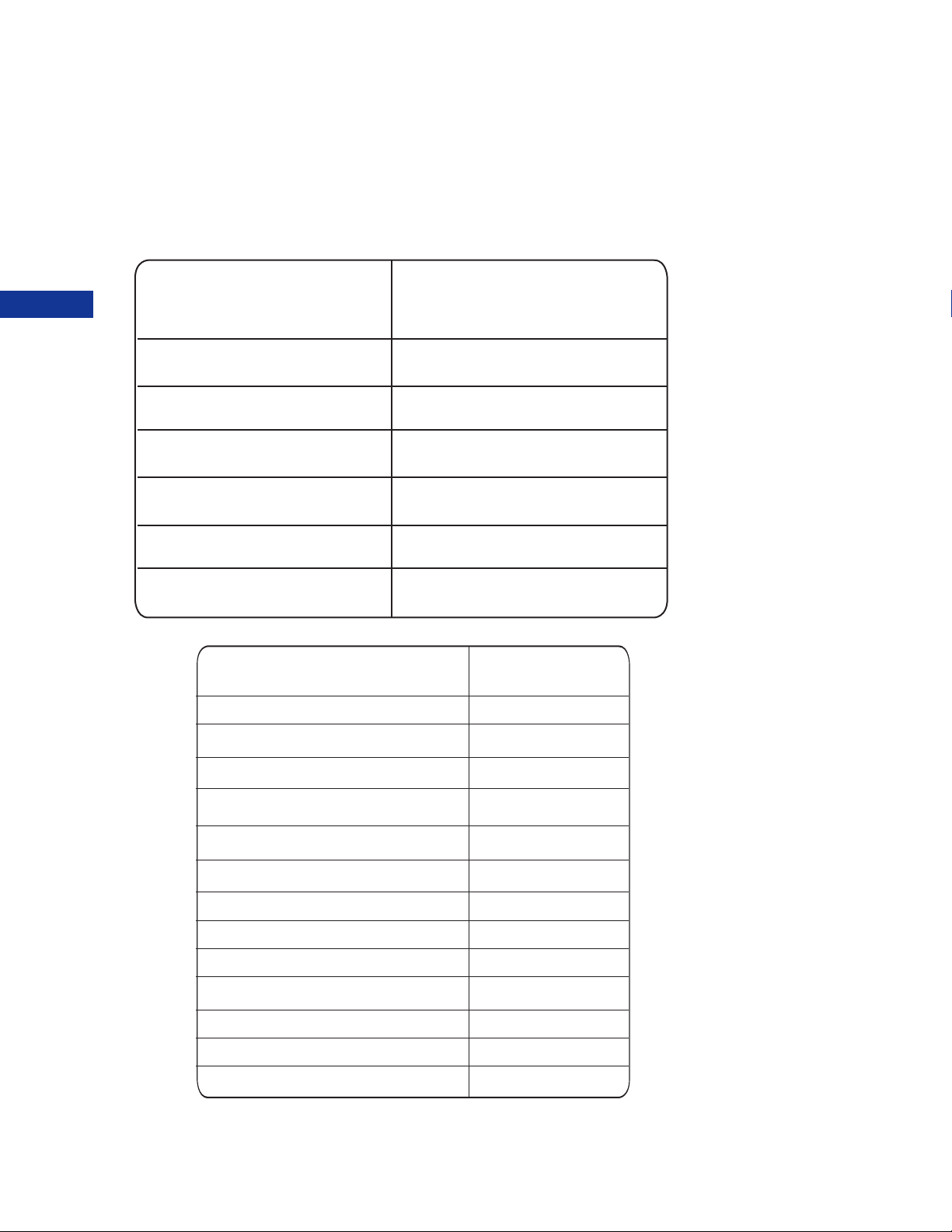
CL600E / CL600E-D
220-240VAC 50Hz /
Input Voltage
110-120VAC 60Hz
Output Voltage 24 VDC
Battery Pack 24 VDC 5AH
Control Panel and Handset
Protection Class IP65 / IP54
Over-duty alarm by LCD
Battery Status by LCD
CL600E
Maximum Safe Load Capacity
Max. height of spreader bar
Min. height of spreader bar
Base closed external width
Base open external width
Base height clearance
Mast height
Overall length
Dual front casters
2 Point Spreader Bar
6 Point Spreader Bar
Emergency Release
Weigh Scale
*ConvaQuip is committed to continuous improvements of our products therefore the
specs, dimensions, and features listed above are for guidance only and subject to
change without prior notice.
6
600 Lb.
81”
37”
27.6”
38”
4.5”
50.1”
49.6”
Yes
Optional
Yes
Yes
Optional
Page 7
ASSEMBLY
Prior to assembly, unpack all parts from the shipping carton and
check for any missing parts. Contact you dealer immediately if a
part is missing.
ASSEMBLY
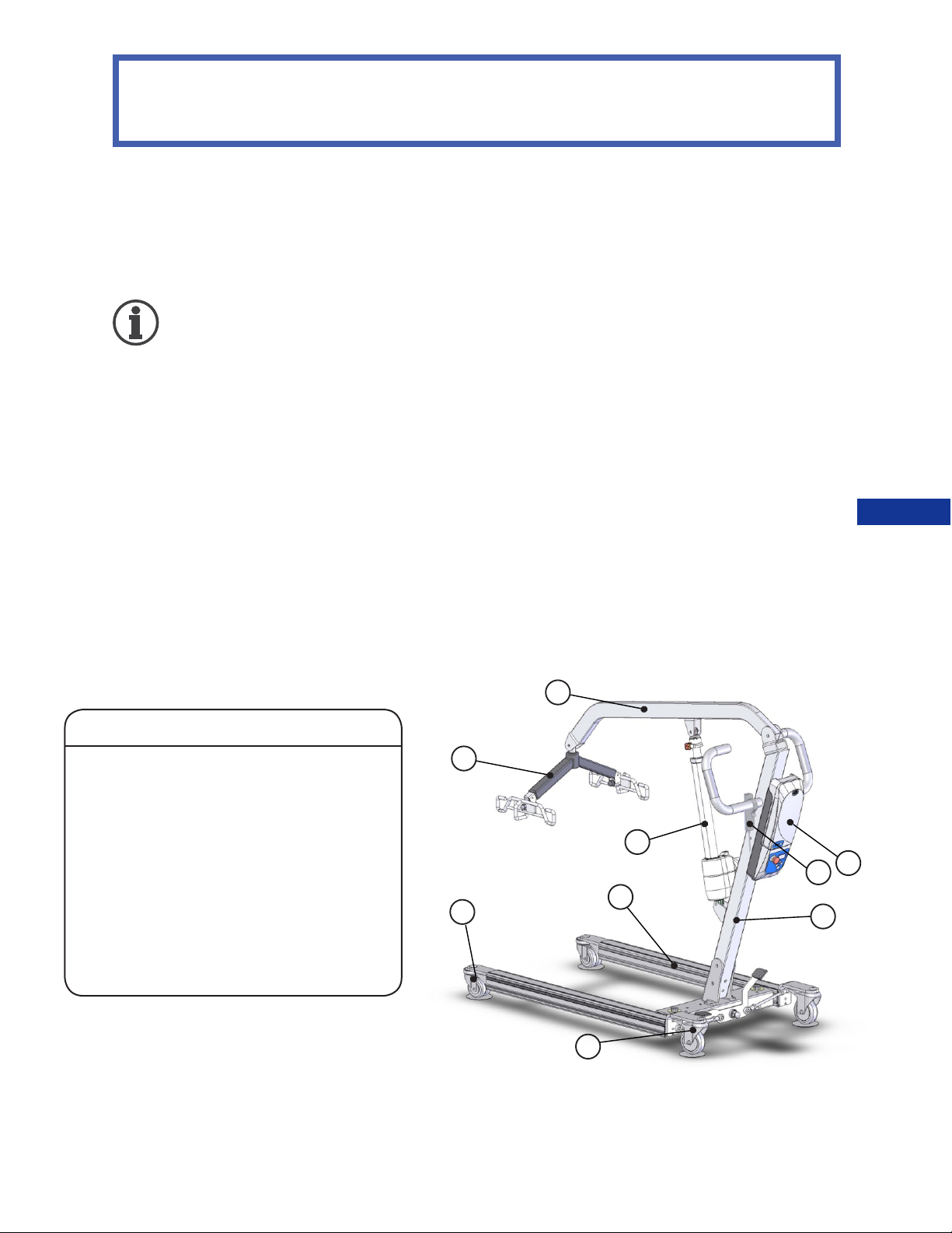
Parts List for CL600E / CL600E-D
1. Boom
2. Mast
3. Base
4. Spreader bar w/ Sling hooks
5. Pendant / Hand Control
6. Actuator
7 Control box and Battery Pack
8 Rear Caster w/ Brake
9. Front dual casters
1
4
6
7
5
9
3
2
8
7
Page 8
ASSEMBLY
STEP BY STEP ASSEMBLY
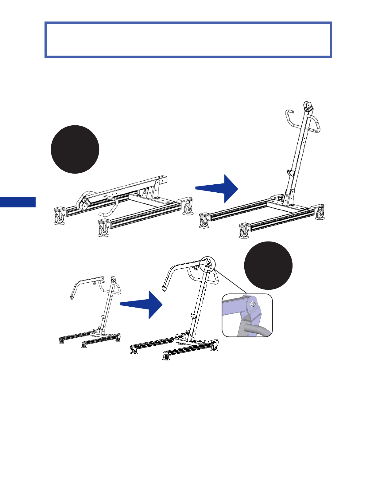
Engage the brakes. Remove the bolts
from the bottom of the mast and base. Pull
the Mast to an upright position. Re-insert
1
the bolts into the holes at bottom of the
mast and tighten the nuts.
ASSEMBLY
2
Attach boom to top of
mast. Re-insert the
bolts into the holes at
bottom of the mast and
tighten the nuts.
翿
8
Page 9
ASSEMBLY
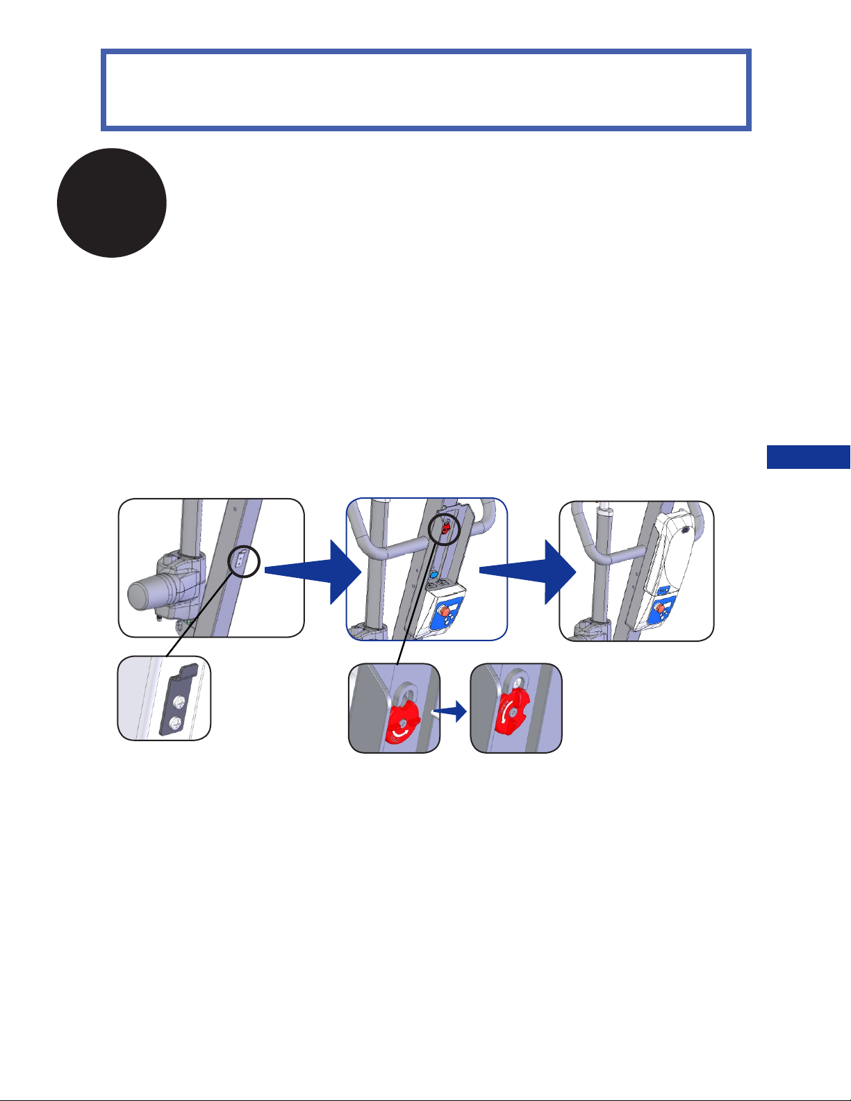
3
BATTERY ASSEMBLY FOR CL600E / CL600E-D
Install the control box. Slide the control box over and onto
the metal tab mounted at the bottom of the Mast. Line up
the control box with the hole at the top of the mast and
insert the screw to hold the control box in place. Secure
the control box by turning the lock mechanism into the lock
position.
ASSEMBLY
9
翿
Page 10
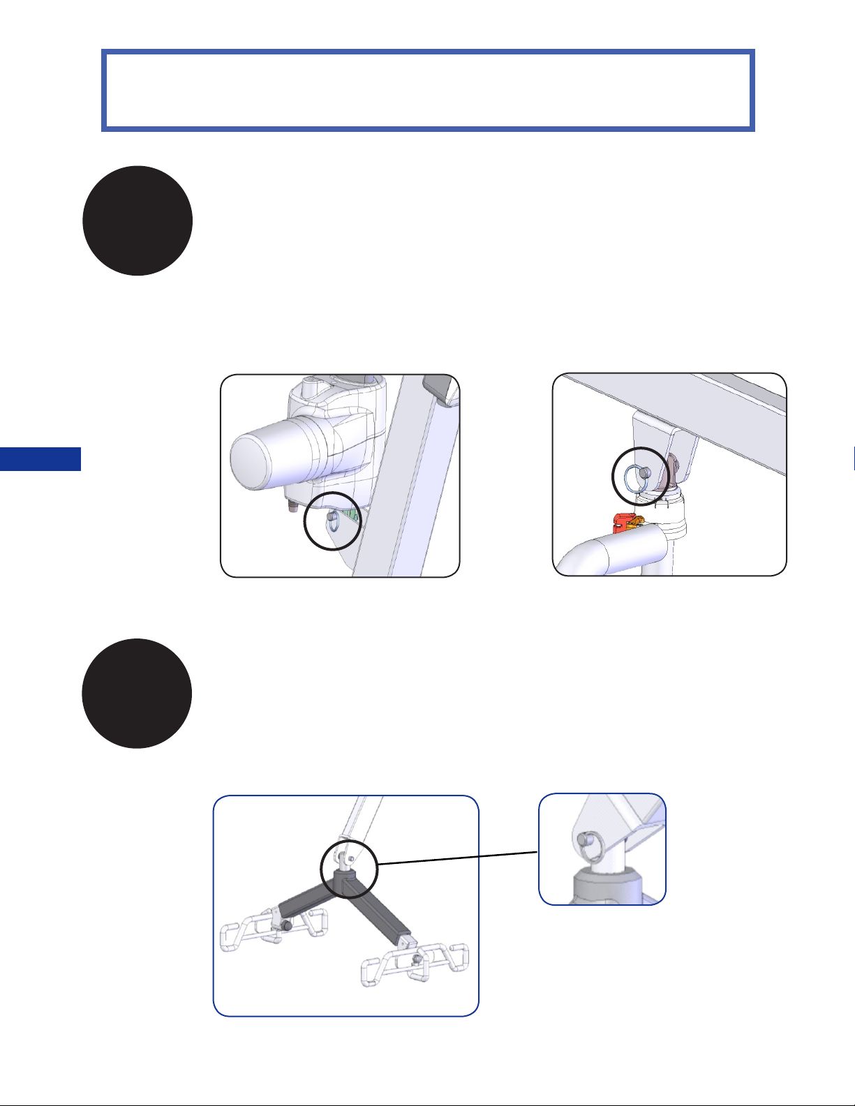
4
ASSEMBLY
ACTUATOR ASSEMBLY FOR
CL600E / CL600E-D
A. Attach the bottom of Actuator to the
bracket on the Mast and insert pin. Insert
keeper ring through hole in pin to secure
base of actuator.
A. B.
B. Attach the top of the Actuator to
the bracket on the Boom and insert
pin. Insert keeper ring through hole
in pin to secure actuator to upper
bracket.
ASSEMBLY
5
SPREADER BAR ASSEMBLY FOR
CL600E / CL600E-D
Attach the spreader bar to the boom and
insert pin. Insert keeper ring to secure
spreader bar to boom.
10
Page 11
ASSEMBLY
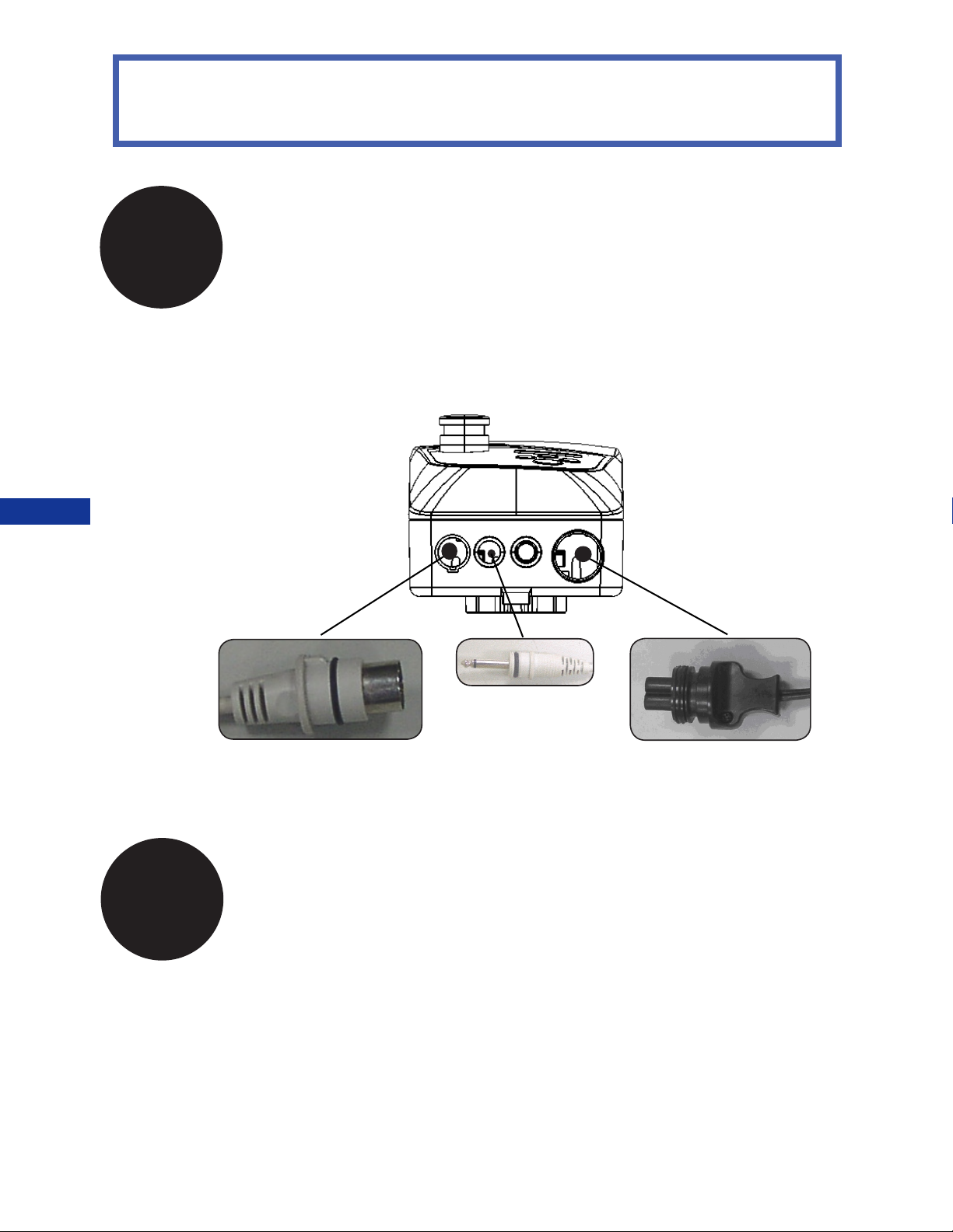
Attach actuator and pendant to the control box.
ASSEMBLY
6
* refer to page 14 for charging instructions
BATTERY PLUG-INS FOR E-series
翿
Actuator Plug
7
翿
Pendant Plug
Tighten all nuts and make sure lift is sturdy before use.
AC Power Plug
翿
11
Page 12
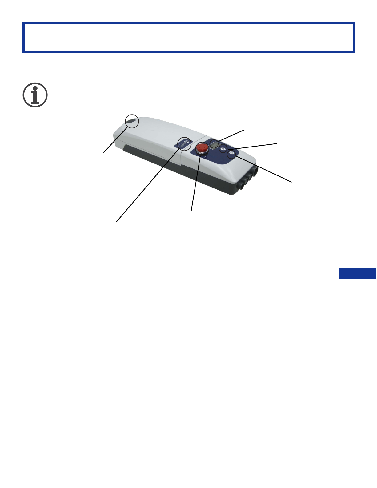
CONTROL BOX INSTRUCTIONS
The following instructions apply to
ConvaQuip CL600E / CL600E-D.
LCD display / LCD
Lifting actuator UP
Battery pack release
Lifting actuator DOWN
Emergency button
Battery indicator
FEATURES:
• Smart charging function for longer battery life
• Battery capacity indicator on battery pack
• Soft start and stop for lifting actuator
• Soft and Hardware over-current protection
• Actuator’s Over-duty protection with sign on LCD
• Emergency stop button interrupts the power supply to the actuators and
makes the actuators stop immediately in case of sudden danger
• Control panel with two buttons (except handset)
• Internal charger
• LCD-display showing battery capacity and indication when the battery needs
recharging.
• Audible alarm for low battery capacity.
• Standard protection class: IP 65
• Pulling-proof design to lock the AC plug
INSTRUCTIONS
OPERATING
12
Page 13
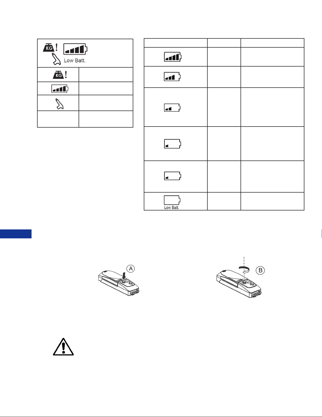
LCD INDICATORS
low battery
overload
battery volume
overused
battery low
(blinking)
Capacity Function
90%
70%
Battery is charged to
around 90%
Battery is charged to
around 70%
50% Battery
Capacity Remaining
翿
50%
Charge batteries
immediately.
25% Battery
25%
Capacity Remaining
Charge batteries
immediately.
Battery is charged
10%
to around 10%
Buzzer Beeps / Only
lowering possible
OPERATING
INSTRUCTIONS
0% Power off
翿
EMERGENCY STOP
Emergency stop button interrupts the power supply to the actuators and
makes the actuators stop immediately in case of sudden danger.
press RED button turn RED button clockwise
LOCKED
*IT’S STRONGLY RECOMMENDED THAT THE BUTTON IS PRESSED DOWN WHEN THE LIFT WILL
NOT BE USED FOR OVER 3 DAYS TO MAINTAIN OPTIMAL BATTERY LIFE AND PERFORMANCE.
UNLOCKED
PATIENT LIFT WILL NOT OPERATE WHILE CHARGING
13
Page 14

FEATURES OF POWER PLUG:
C-CLAMP :
• when the battery is being charged, insert this C-clamp to secure
the power plug.
WATERPROOF COVER:
• when control is being used, this cover can be
used to prevent water ingress.
C-clamp
Waterproof Cover
REMOVE AND INSERT BATTERY PACK:
REMOVE : press button A and pull out in the up direction (Fig.1)
INSERT:
• put the battery pack all the way down to position as (Fig.2).
• while pressing the release button (A), slide into control box
according to the down arrow directions.
• make sure the battery pack won’t slide back off by pulling the
battery pack without pressing the release button.
INSTRUCTIONS
OPERATING
14
Page 15
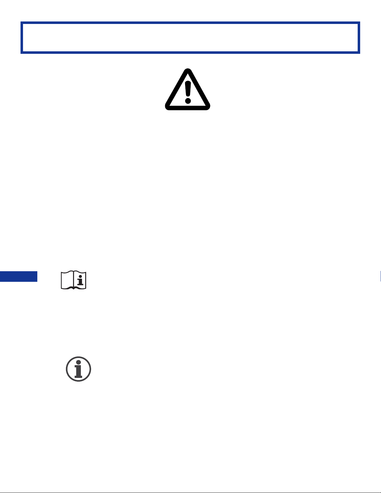
OPERATING INSTRUCTIONS
Double check all assemblies for tightness and
read operating instructions carefully prior to use.
Do not attempt to use patient lift unless the patient
exhibits control over the upper body, strength to
grasp the handles, ability to bear some weight and
flexibility in knees, hips, and ankles.
OPERATING
INSTRUCTIONS
PREPARATION BEFORE LIFTING
• Turn on the power by twisting the RED RESET BUTTON clockwise.
• Press the UP or DOWN button on the hand control once. Check if
the battery indicator lights are on.
• Position the base of the lift around or under the object.
• Widen the base and engage the caster brakes.
Do not attempt to transfer a patient without prior approval of the
person’s nurse. Also, do not transfer without having studied the
instructions and performed several practices in operating the
product. Together (with the patients doctor, nurse, or medical
attendant) select a sling that is both practical and comfortable. The
sling selected should be one that serves the needs of the patient,
while providing the patient with optimal safety. Never interfere with
the lift, unless instructed by the attendant. Have a doctor, nurse,
or medical attendant (experienced in the use of the ConvaLift)
present during the first few times the lift is used to transfer a new
user.
15
Page 16
Turn the lift “ON” by turning the red “RESET”
button clockwise. Turn the lift “OFF” by pressing
down the “RESET” button.
TRANSFER FROM BED
• User/patient should be in the center of the bed.
• Position user onto his/her side by rolling user towards you.
• Roll the sling in half, approximately. The handle on the back section should
face outward when the sling is fitted.
• Position the sling under the user/patient so the commode aperture aligns with
the base of the spine and top of the sling close to the neck.
• Roll user onto the opposite side and position him/her on the flat section of the
sling. This will allow you to unroll the remainder of the sling from the other
side of the user.
• Once the sling has been positioned centrally, feed the leg sections under the
thighs and draw them up between the thighs.
• Raise the head of the bed if this function is available.
• Move the lift slowly towards the user and position the spreader bar over the
user’s/patient’s chest.
INSTRUCTIONS
OPERATING
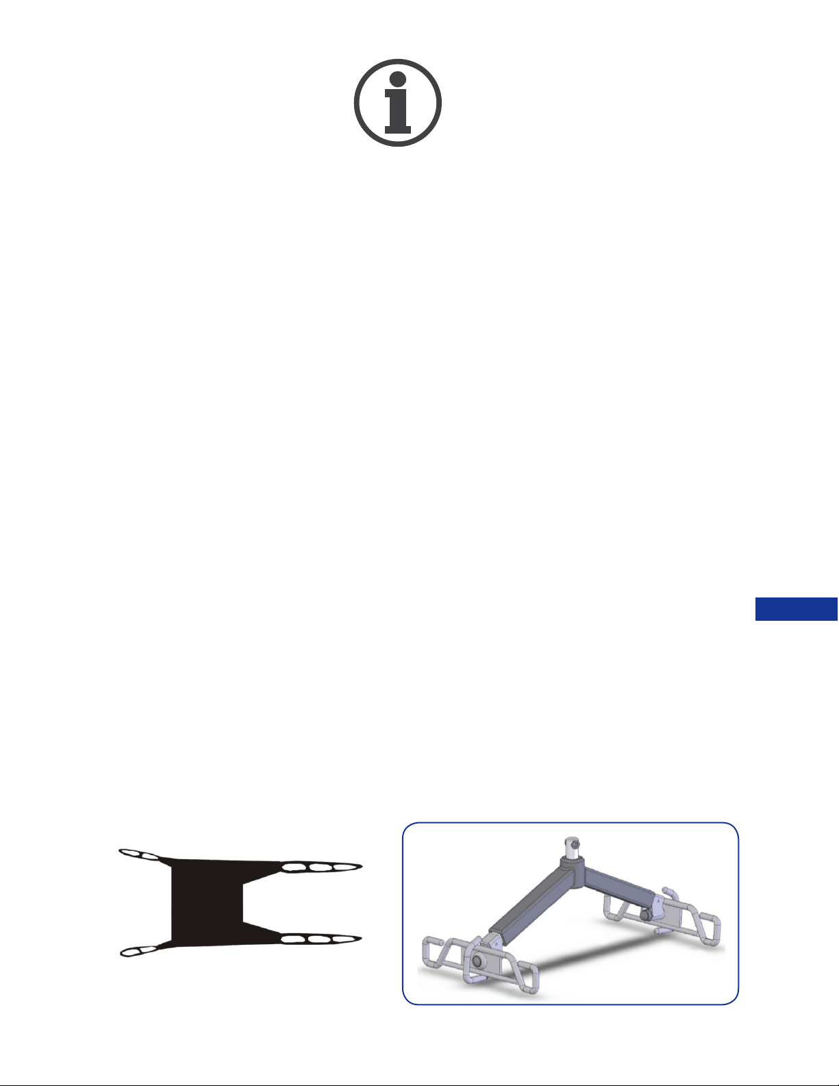
SLING ATTACHMENT INSTRUCTIONS FOR THE
SLING ATTACHMENT INSTRUCTIONS FOR THE
6-POINT SPREADER BAR
6-POINT SPREADER BAR
Attach Loop A of the sling to Hook A on Spreader Bar;
attach Loop B to Hook B; attach Loop C to Hook C; attach
Loop D to Hook D.
B
A
C
D
A
C
16
B
D
Page 17
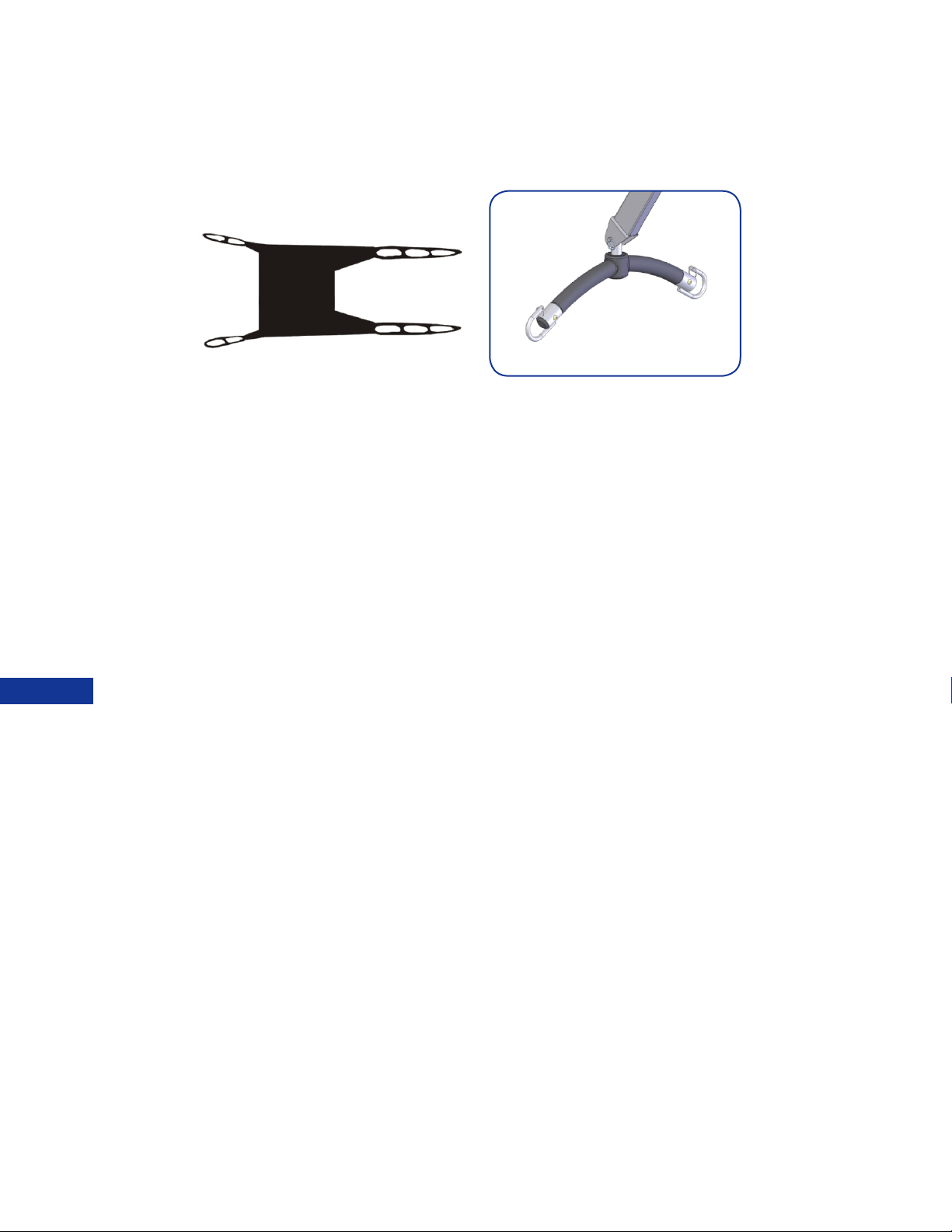
SLING ATTACHMENT INSTRUCTIONS FOR THE
6-POINT SPREADER BAR
Attach Loop A and D of the sling to Hook A on Spreader Bar; attach Loop B
and C to Hook B.
A
B
C
D
B
A
翿
• Lift the user above the bed by using the hand control.
• Pull lift away from bed. Position user over the wheelchair or chair then lower
the patient onto the surface.
Note: Reverse the above procedures when returning the user/patient to bed.
OPERATING
INSTRUCTIONS
17
Page 18
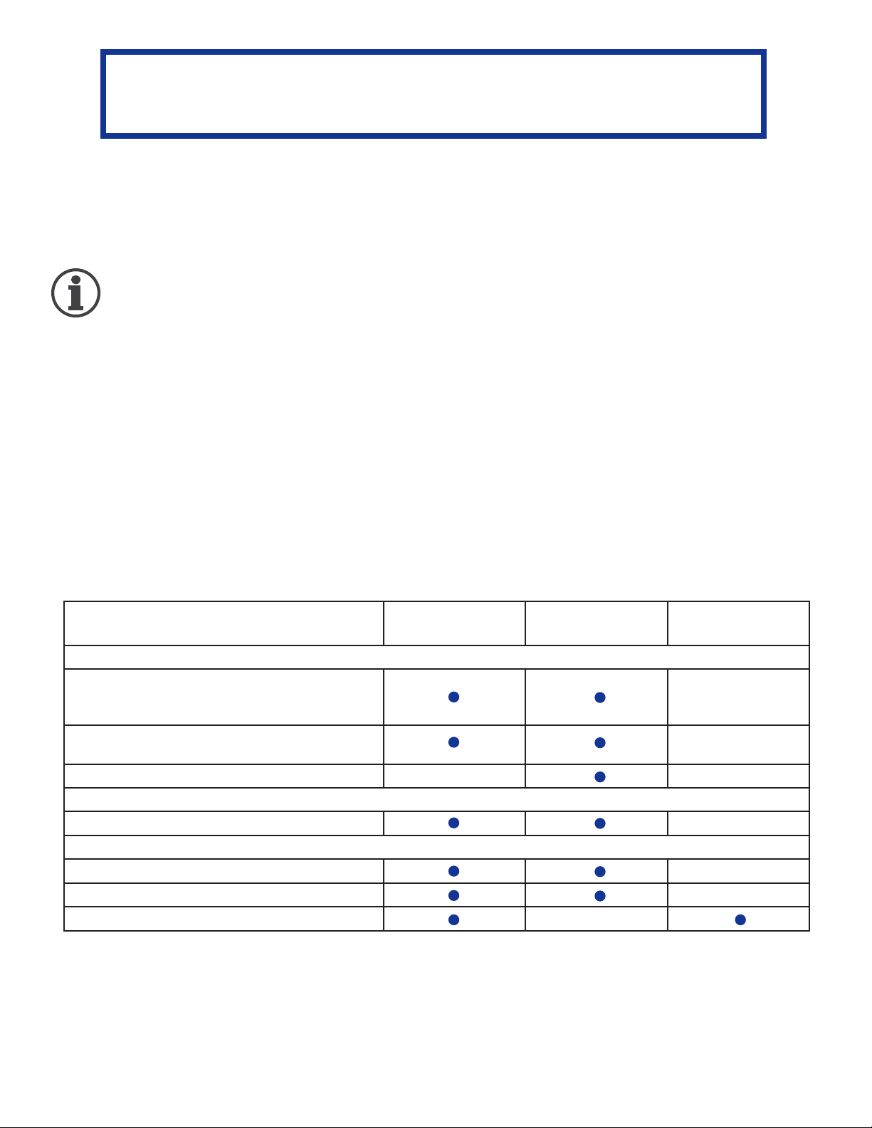
MAINTENANCE & INSPECTION
• The operator of the lift shall inspect the ConvaLift before each use. Check
all bolts for tightness. Make sure the base can be easily widened, and
that all lift parts are in place. Make sure that casters can be turned
freely, and that caster brakes can be engaged. Make certain all
necessary items (i.e. slings, and wheelchairs, etc.) are ready for use.
• At least once a month, the lift should be thoroughly inspected by a
person qualified to recognize any signs of wear and tear, and looseness
of bolts or parts. Replace any worn parts immediately.
• To lubricate, put a drop of oil on the following points when the ConvaLift is
placed into service and every month thereafter: Top of Mast, Spreader
Hinge, and Caster Axles.
BOOM & SPREADER BAR
Check connections between Boom and
Spreader Bar for improper connection,
looseness, or wear
Check connections between Boom and Mast for
improper connection, looseness, or wear.
Check the Boom for bending and deflection.
MAST
Check the Mast for bending or deflection.
BASE & FOOT PEDAL
Check bolts and nuts for looseness..
Check casters and axle bolts for tightness.
Check rubber parts on the casters for deflection
FIRST
RECEIVED
MONTHLY
EVERY 3
MONTHS
18
Page 19
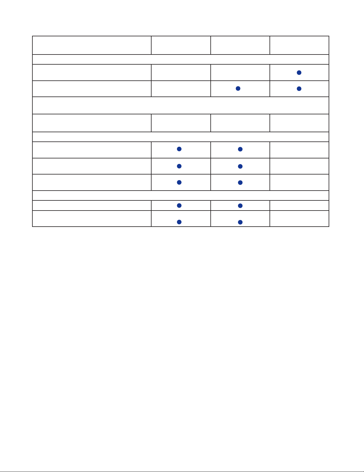
BASE & FOOT PEDAL
Apply grease to caster ball bearings if
needed.
Check welding joints for rust and crack.
CLEANING
AS NEEDED
ACTUATOR & CONTROL BOX
Make sure the control box is firmly affixed
to the mast.
Make sure the actuator is secured to the
Boom and mast with pins and key rings
Make sure actuator plug into control box is
not loose.
SLINGS & SLING HARDWARE
Check sling for wear.
Check sling hardware every time before
use.
FIRST
RECEIVED
17
MONTHLY
EVERY 3
MONTHS
19
Page 20

TROUBLESHOOTING GUIDE
The following list of encountered problems and solutions will assist you
in determining what may be causing your patient lift not to function as
designed. If you have a problem occurring which is not listed below
please contact your dealer or technical support for help. Do not attempt
to repair or replace components or parts on your ConvaLift as this may void
your warranty or cause further problems that may result in patient
injury. Stop using your lift immediately if it is not functioning correctly or
any warning beeps are heard.
I need to re-charge my batteries often or they fail to hold a charge when I
charge them.
• Replace the batteries or battery pack as they are at the end of their life
cycle
• Batteries should be changed every 18-24 months depending on usage
The actuator will either go up or down but not both
• Replace your hand control as it is at the end of its life cycle
• Your control box may be malfunctioning
There is a grinding sound inside the actuator when lifting
• Replace your actuator as the internal gears are stripped
The actuator stops and starts while lifting or lowering
• Replace the batteries or battery pack as they are at the end of their life
cycle
My lift will not operate even though it shows the batteries are charged
• Unplug the AC power cord from the control box as the lift will not work when the
control box/charger is connected to AC Power.
• Check to make sure the hand control is properly inserted all the way into the
control box port.
• Check to make sure the actuator plug is properly connected and inserted all the
way into the control box
• Your hand control needs to be replaced as it is at the end of its life cycle
If there is problem you could not correct, please contact the dealer for assistance.
20
Page 21
EMERGENCY LOWERING MECHANISM
In case there is a failure with the actuator or electronics and the user is left
suspended in mid-air, please follow the procedures below to safely lower the user
to a safer position.
Contact your dealer immediately if standard troubleshooting techniques do not
correct the failure. Do not attempt to lift until all failure and safety issues have
been resolved.
The following instructions apply to the CL600E / CL600E-D
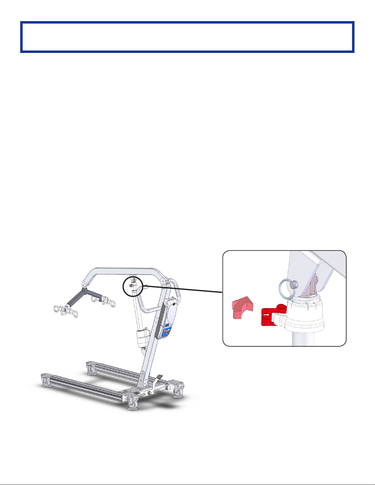
The Quick Release is implemented by a spring loaded lever mounted at the
top end collar of the actuator shaft. DO NOT attempt to turn the Quick Release
mechanism like a knob. This will damage the Quick Release mechanism and
actuator. Manually activate Quick Release by pulling the RED lever with the
arrow symbol in the direction indicated by the arrow towards the opposite red tab.
This will de-clutch the actuator and lower the user safely down.
Note! When the Quick Release is activated, the boom will not lower itself unless
there is weight or force applied in the downward direction.
CL600E / CL600E-D
Pinch pinion red tabs
together
NOTE:
THE EMERGENCY LOWERING DEVICE IS INTENDED FOR USE
DURING LIFT FAILURE. THIS DEVICE WILL ALLOW LOWERING OF
PATIENTS ONLY. PLEASE CONTACT YOUR DEALER IMMEDIATELY IN
CASE OF FAILURE.
21
Page 22

NOTES
22
Page 23
ConvaQuip Ind., Inc.
WARRANTY AND RETURN GOODS POLICY
WARRANTY POLICY:
ConvaQuip offers a limited warranty on ConvaLifts, slings and accessories to be free of defects in workmanship
and product performance. This warranty is extended only to the original purchaser/user and is therefore non
transferrable. Any warranty claims must be submitted through an authorized dealer or distributor that sold the
original product with proper proof of sale and serial number supplied. Prior authorization from ConvaQuip is
required for any warranty replacement and we reserve the right to replace parts and or accessories in lieu of sending
complete new patient lifts. Dealers and distributors will be billed for any advance warranty replacement items
shipped and credited at 100% only when the defective items have been returned to ConvaQuip and proven
defective. Product returned without a ConvaQuip return authorization will be refused. Returns received 30 days
after the issuance of a return authorization will also be refused as the authorization will have expired. The final
disposition of warranty claims will be subject to our inspection of the returned items. ConvaQuip has the right to
determine valid claims based on the individual circumstances of each claim. Warranty claims will be denied should
evidence of the following be det ermined:
Misuse of product , modification of product or failure to maintain as per the owner’s manual
Serial number removed or defaced
Normal wear and tear
ConvaQuip warrants the following products and components for the time period specified:
Lift frames and spreader bar: 3 years
Actuator: 2 years
Parts including casters, control box, PCB, pendant, charger: 2 years
Batteries: 1 year
Weigh Scale: 2 years
Hydraulic pumps: 1 year
Reusable slings: 6 months
ConvaQuip Single Patient Slings are designed for limited use with one patient and may not be washed. ConvaQuip will replace
any disposable slings found to have a manufacturing defect. Normal wear and tear will not be covered under warranty.
RETURN GOODS POLICY:
ConvaQuip will allow goods to be returned only with prior authorization and a valid RA number issued by the RA
coordinator. RA’s will only be provided for items invoiced within 30 days of the initial RA request. All returns must
be received at ConvaQuip within 30 days or the RA will expire. The returning package must be clearly marked with
the RA number or the shipment will not be received or any credit issued. When a part is returned to ConvaQuip for
warranty inspection a $50 service charge will apply if the part is not defective. Returns are subject to a minimum re stocking fee of 20% or more depending on the condition of the returned items. Where an item was ordered
incorrectly according to your purchase order or the customer no longer wants the item(s) returning freight is the
responsibility of the dealer/customer not ConvaQuip.
Patient lifts may not be returned unless the following has occurred:
The wrong lift was shipped in error by ConvaQuip
The lift is heavily damaged or defective out of the box
Please note that lifts being returned must be in the original carton and all parts and components included with the
return. Failure to comply with this requirement will incur higher restocking fees or a rejection of the return. Slings,
parts and accessories may only be returned if they have not been used. There are no exceptions to this provision.
ConvaQuip reserves the right to issue credit amounts based on strict adherence to this policy.
WARRANTY
Tel: 800-637-8436-
P.O. Box 3417 Abilene, TX 79604
Fax: 325-677-7217 www.ConvaQuip.com
23
Page 24
L.L.C.
ConvaQuip LLC
P.O. Box 3417
Abilene, TX 79604
tel. 325-677-4177
free 1-800-637-8436
www.convaquip.com | ConvaQuip
®
 Loading...