

Page 1
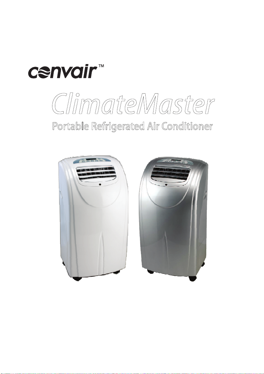
ClimateMaster
Portable Refrigerated Air Conditioner
ClimateMaster CM12RW
CM12RCW, CM12RCS
Instruction Manual
Page 2

Please read these instructions prior to using the
appliance and save them for future reference.
Waste electrical products must not be disposed of with
household waste. This product should be taken to your local
recycling centrefor safe treatment.
Page 3
INTRODUCTION
THANK YOU for choosing a Convair
Air Conditioner. This appliance has
been carefully engineered to bring
you trouble-free personal air
conditioning. Please read this
manual carefully so that you take
full advantage of the many benefits
your Convair provides.
This appliance is not intended for use
by persons (including children) with
reduced physical, sensory or mental
capabilities, or lack of experience and
knowledge, unless they have been
given supervision or instruction in
using the appliance by a person
responsible for their safety.
Children should be supervised to
ensure that they do not play with the
appliance. Do not place anything
through the ventilating slots.
Be sure the appliance has been
securely and correctly installed
ac c o rdin g to th e in s t alla t i on
instructions contained within this
manual.
Personal Cooling
Your Convair cooler is a portable air
condit ioning u nit that s upplies
refrigerated air to a personal area
within a room. It is not intended to
function as a house or room air
conditioner.
Energy Saving Tips
Do not locate the air conditioner
D
where furniture or other objects can
obstruct the air flow.
D
Keep curtains and blinds closed
during the hottest part of theday.
D
Keep the filter clean.
D
Set the air conditioner to maximum
cooling and high fan speed initially,
then adjust to a comfortable setting.
D
Do not wait until the room is
excessively hot before using the air
conditioner.
CONTENTS
Introduction......................................1
Safety ..............................................2
Component location.........................3
Installing the exhaust hose ..............4
Control panel ...................................5
Remote control ................................6
Operation.........................................7
Functions......................................8-9
Maintenance ..................................10
Troubleshooting .............................11
Specifications ................................12
1
Page 4
SAFETY
General Safety
For indoor use only.
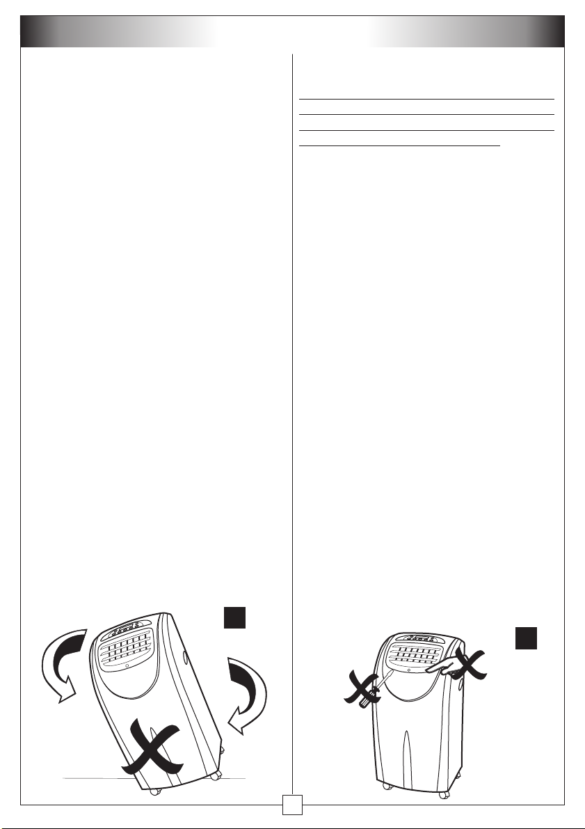
Transport the air conditioner in an
upright position only, or leave it in an
upright position for at least 2 hours
before use (Fig 1).
Use only in the upright position on a flat
level surface and at least 50cm from any
objects.
Do not place objects on the air conditioner
or restrict air inlets / outlets (Fig 2).
Closely supervise any children and pets
when the air conditioner is in use.
Do not store or operate the appliance near
any flammable substances.
During operation, water will collect in the
bottom tank of the air conditioner. Be
careful when moving the unit to prevent
water from spilling.
Electrical Safety (cont)
Cau tio n! bef ore c onne cti ng the
electrical power cord to a power outlet,
check that the air conditioner voltage is
the same as your power supply (refer to
the rating label located on the back of the
unit). Ensure the power supply is correctly
earthed and rated.
Plug the air conditioner directly into a
properly installed power outlet. Never use
an extension cord, double adaptor or multi
power outlet board to run this air
conditioner.
Do notpull the unit along by thepower cord
or place the power cord near a source of
heat. Always unroll the power cord
completely before use.
If the power cord is damaged, in order to
avoid a hazard it must be replaced by an
electrician or similarly qualified person or
service agent.
Switch off andunplug when not in use.
Electrical Safety
Ensure theappliance hasbeen installed in
accorda n c e w i t h n a t i o n al w i ring
regulations.
1
Do not use in humid environments such as
bathrooms or other steamy or wet areas.
Do not touch or operate the air conditioner
with wet or damp hands or when standing
barefoot.
2
2
Page 5
COMPONENT LOCATION
3
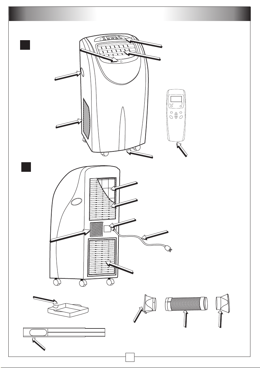
Handle
Air Intake
4
Exhaust
Air Outlet
Remote
Sensor
Drain
Air Filter
Air Intake
Rating
Label
Control panel
Air outlet
OSC
OSC
Mode Temp Speed
On / OffTimer
Remote
Control
Power cord
Drain
Tray
Window Kit
Air Intake
Exhaust
Fitting
(cooler end)
3
Exhaust Hose
Exhaust
Fitting
(window
end)
Page 6
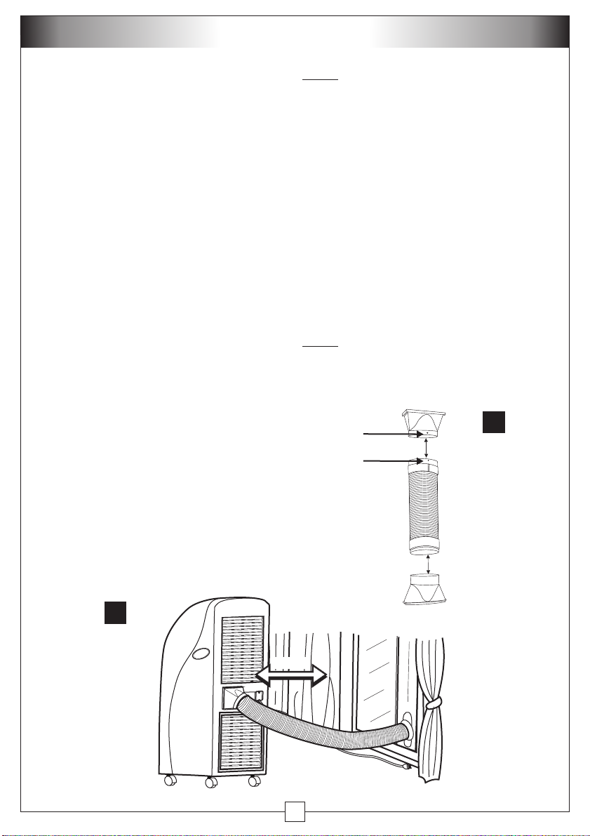
INSTALLING THE EXHAUST
Assembling the exhaust hose (Fig 5)
Step 1:
Fit the square exhaust fitting
onto the hose end with the 2 ‘pips’. The
pips will lock into the holes.
Step 2:
Fit the oblong exhaust fitting
onto the other end of the hose.
Installing the exhaust hose to the air
conditioner (Fig 6).
Step 1:
Position the square exhaust
fitting above the grooves on the exhaust
air outlet, with the open end facing down.
Step 2:
Push the hose fitting down into
the outlet until it is completely covered.
Installing the exhaust hose to the
window (Fig 6).
Step 1:
Snap the oblong connector into
position on the window attachment.
Step 2
: Open the window and fit the
adjustable window attachment. Extend
the attachment as required and lock into
place with the wing nut. Ensure the outlet
is not obscured. The window attachment
can be installed horizontally or vertically,
depending on the window type.
Note!
The minimum distance required
from the operating air conditioner to
any obstructing objects or walls is
50cm (Fig 6).
Keep the exhaust hose as short and
straight as possible and minimise
kinks. This will maximise the cooling
performance.
Don’t use extension pieces for the
exhaust pipe as this will reduce the
cooling performance.
Hot air and possibly mist will be
emitted from the exhaust hose.
Note!
It is critical to the cooler’s
performance that the hot exhaust air
is completely removed from the space
being cooled.
hole
locating
pip
5
6
50cm
4
Page 7
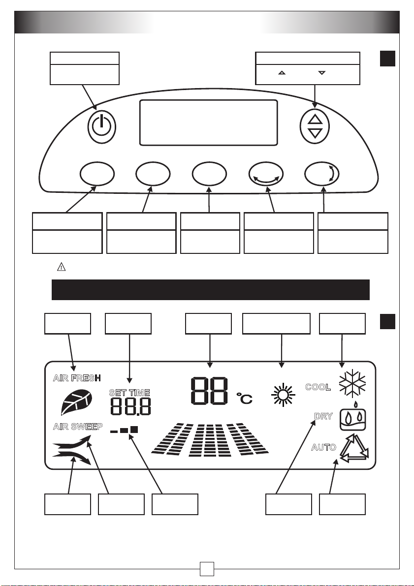
CONTROL PANEL
Power ON / OFF button
Press to turn the air
conditioner on and off
ON / OFF
Mode Select
button
Press to cycle from Auto,
Heat, Fan, Cooling and
Dry modes.
NOTE!
Negative Ion
Indicator
Temperature & Timer adjust button
Press to increase, to decrease
the set temperature or timer
TEMP/TIME
OSCOSCTIMERSPEEDMODE
Fan Speed
control button
Press to cycle the fan
speed between low,
medium and high
Timer Set
button
Press to enter the
timer setting mode
Horizontal Swing
Vane button
Press to start or stop
the outlet vanes sweeping
from side to side
Vertical Swing
Vane button
Press to start or stop
the outlet vanes sweeping
up and down
To avoid damage to the control panel, do not operate with sharp objects.
CONTROL PANEL DISPLAY
Timer Duration
Indicator
Temperature
Display
Heating Mode Indicator
(only CM12RCW &
CM12RCS)
Cooling Mode
Indicator
7
8
AIR FRESH
AIR SWEEP
Sweep Indicator
(Horizontal)
SET TIME
Sweep Indicator
(Vertical)
h
Fan Speed
Indicator
HEAT
COOL
DRY
AUTO
Dry Mode
Indicator
Auto Mode
Indicator
5
Page 8
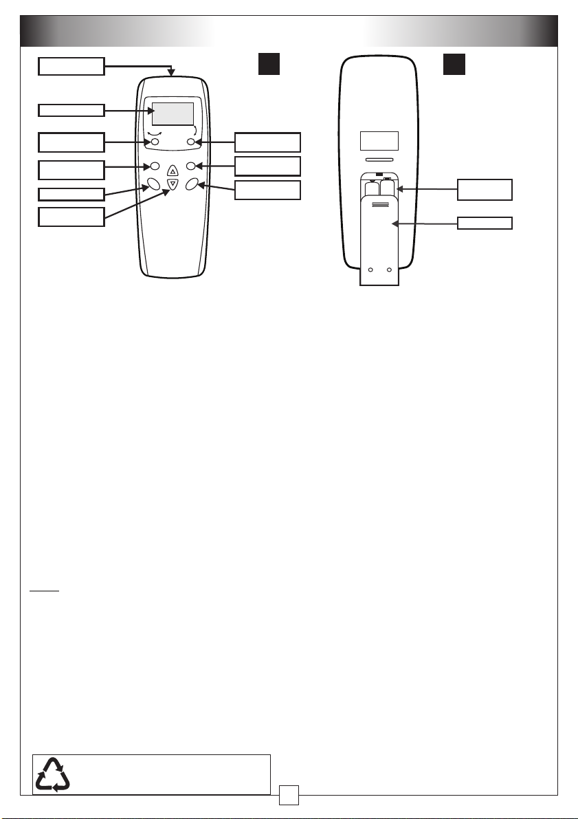
REMOTE CONTROL
Signal
transmission point
Display area
Sweep button
(horizontal)
Mode Select
button
Timer button
Temperature /
Timer adjust buttons
OSC
OSC
Mode Temp Speed
On / OffTimer
9
Sweep button
(vertical)
Fan Speed
adjust button
Power ON / OFF
button
Preparation before operation
Remove the battery cover and insert new
batteries
(AAA), making sure the + and are matching the compartment markings
(Fig 10)
.
During Operation
If the display disappears, or the remote
control will not operate the air conditioner,
the batteries mayneed to be replaced.
If there is no display, or only part display,
remove the batteries and replace with new
ones. If this does not solve the problem
contact your nearest service centre for
advice.
Note! he air conditioner must be
T
plugged in and switched on for the
remote control to operate the air
d
con itioner. To use, point at the signal
receiving wi dow on the front panel and
press the remote but on. The air
n
t
conditioner will “beep” when a signal
has been received. If there is no beep,
pressthe remote button again, ensuring
it is within range 6 metres) of the air
(
conditioner.
NOTE:
WASTE BATTERIES SHOULD
!
BE DISPOSED OF CORRECTLY
10
Battery
compartment
Battery cover
If there are two of the same air
conditioners installed, they cannot be
controlled separately. When you operate
either remote, it will turn on both air
conditioners if they are both within signal
range (6 metres).
Care of your remote control
Don’t let the remote control drop onto hard
surfaces or be subjected to sudden
shocks in any way. The warranty does not
cover misuse or accidental damage.
Don’t place the remote control in direct
sunlight, or near extremes of temperature.
This will affect the control’s temperature
reading.
Don’t allow the remote control to get wet.
Don’t place near strong electromagnetic
waves.
Don’t mix old and new batteries ! If the
remote control will not be used for a long
time, remove the batteries to avoid
corrosion.
6
Page 9
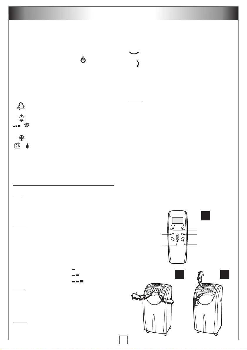
OPERATION
Starting the air conditioner
Step 1: Ensure the cooler is plugged in and
switched on.
Step 2:
Press the ON/OFF button on the
remote control or ON/OFF button on the
control panel to start the airconditioner.
Step 3:
Press the MODE button on the
control panel or MODE button on the
remote control to select the desired
operating mode (Fig. 11):
Step 4:
Auto mode
operating mode
Heating mode
Fan mode
cooling)
Cooling mode
Dry mode
removal from the air
Press / on the control panel
- automatic selection of
- reverse cycle heating
- Fan only operation (no
- refrigerated cooling
- refrigerated moisture
r s
or on the remote control to select the
desired temperature.
The temperature setrange is 16°C-31°C
Do not set the cooling temperature too
!
Tip
low. This will consume more power. 24°C is
the recommended set temperature, with
high fan speed.
Changing the set temperature will
Note!
have no effect in FAN or DRY modes.
Step 5:
Press the SPEED button on the
control panel or the remote control to adjust
the fan speed. Each press will cycle the fan
speed as below:
Low speed
Medium speed
High speed
In Dry mode, the fan will always be
!
Note
set to low speed. In heating and cooling
modes, the fan may automatically change
to high speed to protect the refrigeration
system.
In Cooling mode, the fan will continue
Note!
to run even when the compressor has
cycled off.
Step 6:
The air conditioner has 2 sets of
motorised air direction vanes. Press
the OSC buttons on the control panel or the
remote control to turn the vanes on or off.
OSC
operates the horizontal vanes - air
will sweep from side to side(Fig 12)
OSC
operates the vertical vanes - air will
sweep up and down(Fig 13)
Press the buttons again tostop the sweeping
vanes.
Do not attempt to move the
motorised vanes byhand !
Note!
The cooler will store the last mode
selected in memory and return to this when
next switched on.
Important !
During cooling and heating
mode, water will c ollect i n the air
conditioner’s tank. In cooling mode this
water is recirculated and some will be
exhausted out with the hot air, but will slowly
fill up the tank. This occurs more quickly in
humid conditions. In heating mode there is
no recirculation. If the tank should fill, error
code “E2” will appear on the control panel,
the unit will ‘beep’ 10 times and then shut
down. Refer to the Maintenance section for
draining the tankshould this occur.
11
OSC
OSC
Step.3
Step.4
Mode Temp Speed
On / OffTimer
Step.6
Step.5
Step.2
12
7
13
Page 10
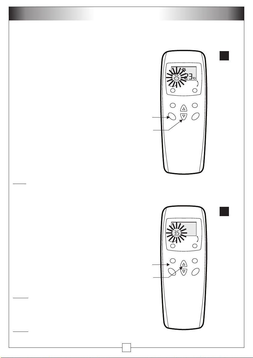
FUNCTIONS
Timer Function - Remote Control
setup
The air conditioner is fitted with a timer
function. This can be set so that the air
conditioner is operating before you wake
up, or to be cooling when you get home
from work, up to 12 hours in advance. To
use this function, the cooler must be
plugged in and ready to operate.
Setting the OFF time
Step 1: ON
With the air conditioner ,
press the TIMER button on the remote
control. The display will show in the
bottom LH corner.
(Fig 14)
0.0
Step.1
Step.2
OSC
Mode
Timer
Temp
14
OSC
Speed
On / Off
Step 2:
Press the TEMP/TIMER button to
adjust the time in 0.5 hour increments
from 0.5 - 12 hrs.(Fig 14 shows the cooler
will turn offafter 2.5 hrs)
Note
!
When the air conditioner is
working, only the TIMER OFF can be set.
When the air conditioner is off, only the
TIMER ON can be set.
Setting the ON time
Step 1: OFF
With the air conditioner ,
(Fig 15)
press the TIMER button on the remote
control. The display will show in the
0.0
bottom LH corner.
Step 2:
Press the TEMP/TIMER button to
adjust the time in 0.5 hour increments
from 0.5 - 12 hrs (Fig 15 shows the cooler
will turn on after 3.5 hrs).
Note!
Remember to have the remote
control within range of the air conditioner.
The cooler will “BEEP” with each button
press.
Step.1
Step.2
OSC
Mode
Timer
Temp
15
OSC
Speed
On / Off
Note!
Pressing theTIMER button after it
is set will cancel theTIMER.
8
Page 11
FUNCTIONS
How to cancel the timer
To cancel the timer, press the TIMER
button when either the TIMER OFF or
TIMER ON has been set. The SET TIME
will revert to and will disappear after 5
seconds.
Setting the timer at the cooler
Follow the same setting procedures as
above, for both TIMER OFF and TIMER
ON functions, by pressing the TIMER
button on the control panel.
and the timer durations in hours will be
displayed. Adjust by pressing the
TEMP/TIMER button to increase or
decrease in 0.5 hr increments.
To cancel the TIMER, change the SET
TIME to 0.0 h - after 2 seconds the SET
TIME will disappear.
0.0
SET TIME
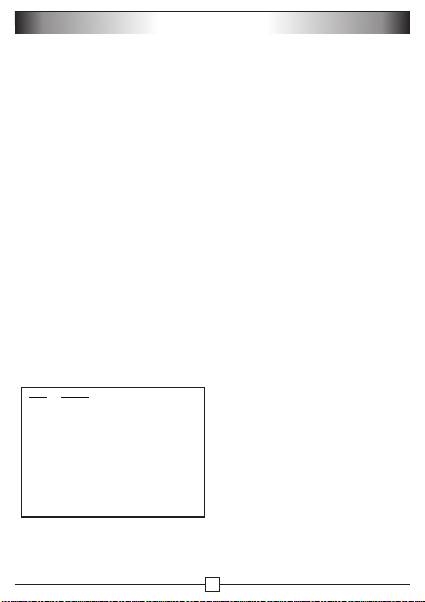
Self check function
The air conditioner incorporates its own
self diagnostics. The following table
shows the code and problem.
Code Problem
E1
E2 Water tank is full (cooler will ‘beep’ 10
E3/E4/ Refrigeration pipe is damaged - contact a
E5 service centre for repair
Indoor temperature or coil sensor is
damaged - contact a service centre for
repair
times to alert you) - refer maintenance
section for draining the tank
9
Page 12
MAINTENANCE
Always disconnect the air conditioner from the electrical mains before cleaning
or draining.
To maximize the efficiency of the air conditioner, clean regularly.
Cleaning the housing
Use a soft, damp cloth to wipe the body clean.
Never use aggressive chemicals, spirits, detergents, chemically treated cloths, or
other cleansing solutions. These substances could possibly damage the cabinet
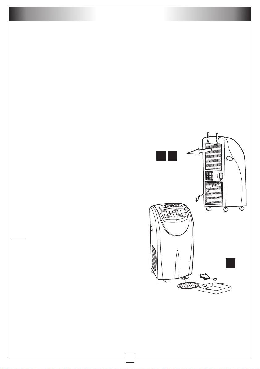
Cleaning the filter
Remove the filter as shown (Fig 16A).
Use a vacuum cleaner or tap the filter lightly to remove loose dust and dirt and then
rinse thoroughly under running water (no hotter than 40°C).
Dry thoroughly before replacing.
Note! Never operate the air conditioner without the filter.
A
Draining the Air Conditioner
To drain the air conditioner, place it over a
drain, or under
put the drain tray (provided)
16
Push down on the
2 top tabs and pull
outwards to release
the air filter
the drain point before removing the drain
plug, as the water will flow out as soon as the
plug is removed.
Remove the plug at the bottom front of the
appliance and allow the tank to completely
drain (Fig 16B).
.
Note
! Always replace the drain plug
immediately after draining.
End of season storage
Drain any water from the unit.
·
Operate the unit in ventilation only mode for a few hours, so as to
·
:
thoroughly dry the inside of the cooler.
·
Clean or change the filter.
·
Unplug and carefully store the power cord and plug end.
Replace in the original carton or cover for storage.
·
10
B
Page 13
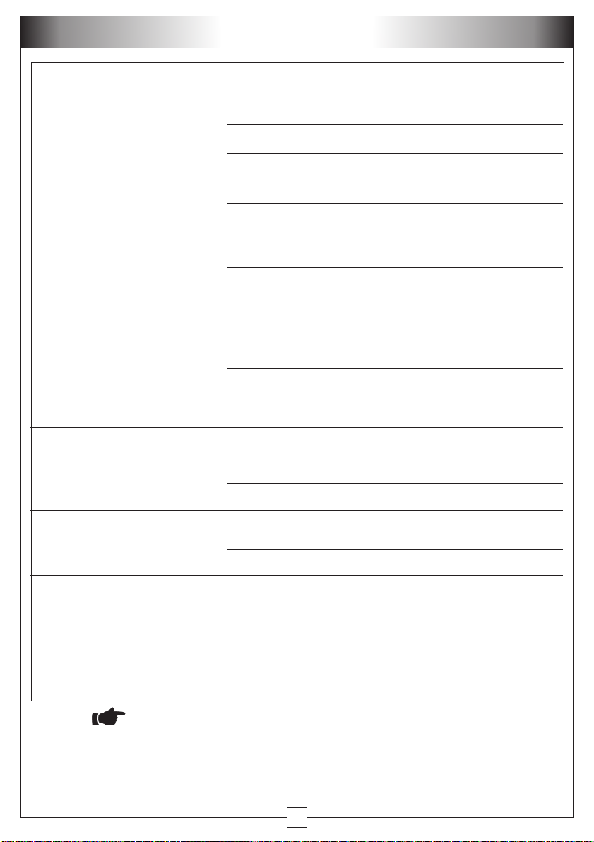
TROUBLESHOOTING
Problem Check
The air conditioner does
not run.
The air conditioner has little
effect (firstly ensure that the
room being cooled is not too
large for the stated capacity
of the air conditioner).
The air conditioner is not as
cool as it once was.
Is the air conditioner plugged in ?
Is there a power failure ?
Is the "WATER FULL" error code “E2” flashing?
Drain the tank as shown (Fig 16).
Is the room temperature below the set temperature ?
Is there direct sunshine ? Remember to close
curtains or blinds.
Are windows or doors open ?
More people in the room will generate more heat.
Is there something in the room producing excessive
heat ?
Is the exhaust fitted correctly or obstructed ? All
exhaust air needs to be completely removed from
the room.
Is the filter dusty or dirty, restricting the airflow ?
Is the air inlet or outlet blocked ?
Is the room temperature below the set temperature ?
The air conditioner is too
noisy.
The compressor will not run.
Is the air conditioner positioned unevenly, so as to
create vibration ?
Is the floor beneath the air conditioner uneven ?
It is possible that the overheat protection for the
compressor is on. Wait for it to reset.
Note: when changing between different modes
(cooling to fan or heating mode etc) the compressor
will turn off. A 3 minute delay will occur before the
compressor will turn on again.
Never try to dismantle the air conditioner yourself.
In case of problems that cannot be fixed by using the above guide,
or if service on your air conditioner is required, please contact your
dealer or designated service agent.
11
Page 14
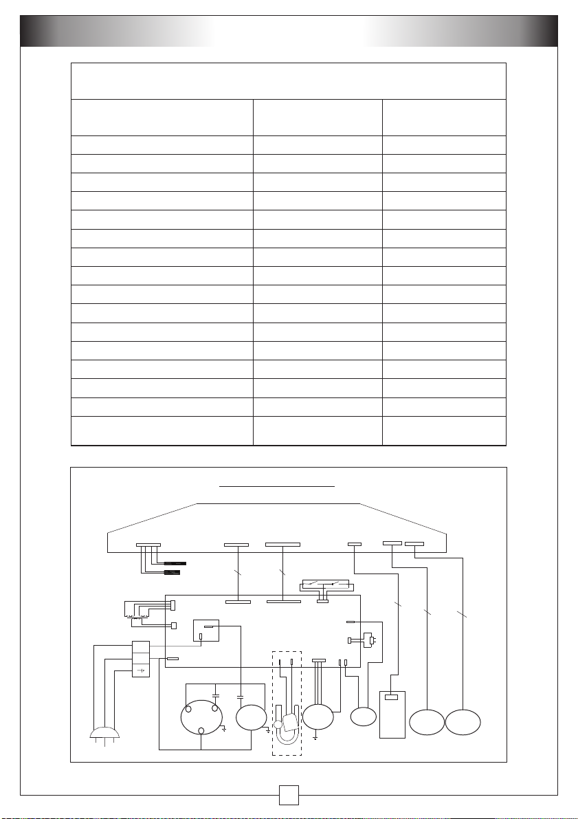
SPECIFICATIONS
SEELEY INTERNATIONAL - CLIMATE MA ST ER
PORTABLE AIR CONDITIONER
Model
Function
Cooling Capacity (Watts) †
Heating Capacity (Watts) †
Dehumidifying Capacity (L/hr)
Air Flow Volume (m / hr)
Noise Level - Sound Pressure (dB(A))
Power Supply
Input Power (Watts)
Input Current (Amperes)
Fuse Type
Refrigerant Type / Charge (kg)
High Side Pressure - Maximum (MPa)
Low Side Pressure - Maximum (MPa)
Water Ingress Protection Rating
Weight (kg)
Dimensions (mm)
(width / depth / height)
3
†Based on manufacturer's test results using the Air Enthalpy method
ClimateMaster CM12RW
ClimateMaster CM12RCW
ClimateMaster CM12RCS
Personal Cooling Personal Cooling & Heating
3,500 (12,000 Btu/hr) 3,500 (12,000 Btu/hr)
- 3,500 (12,000 Btu/hr)
2.5 2.5
310 310
£ 52 £ 52
220-240 V ~, 50 Hz 220-240 V ~, 50 Hz
1300 1350
6 6.2
3.15 A / 250V 3.15 A / 250V
R407C / 0.61 R407C / 0.61
2.7 2.9
0.6 0.7
IPX0 IPX0
40 40
445 / 350 / 870 445 / 350 / 870
WIRING DIAGRAM
CONTROL PANEL
PIPE
ROOM
L
N
R
3-PIN
SUPPLY
PLUG
As a policy of continual product improvement, this manual, its contents and specifications are subject to change without notice.
COMPRESSOR
C
S
7 WIRE
LOOM
CONDENSOR
FAN
8 WIRE
LOOM
EVAPORATOR
4
FAN
WAY
- - - REVERSE CYCLE ONLY
PUMP
3 WIRE
LOOM
REMOTE
CONTROL
SENSOR
SWING
MOTOR
(HORZ)
5 WIRE
LOOM
SWING
MOTOR
(VERT)
5 WIRE
LOOM
12
Page 15
NOTES
13
Page 16
It is the policy of Seeley International to introduce continual
product improvement. Accordingly, specifications are
subject to change without notice. Please consult with your
dealer to confirm the specifications of the model selected.
Service
Australia 1-300-650-644
seeleyinternational.com
133003-E
133010-E
seeleyinternational.com
1112
AU 1112
 Loading...