


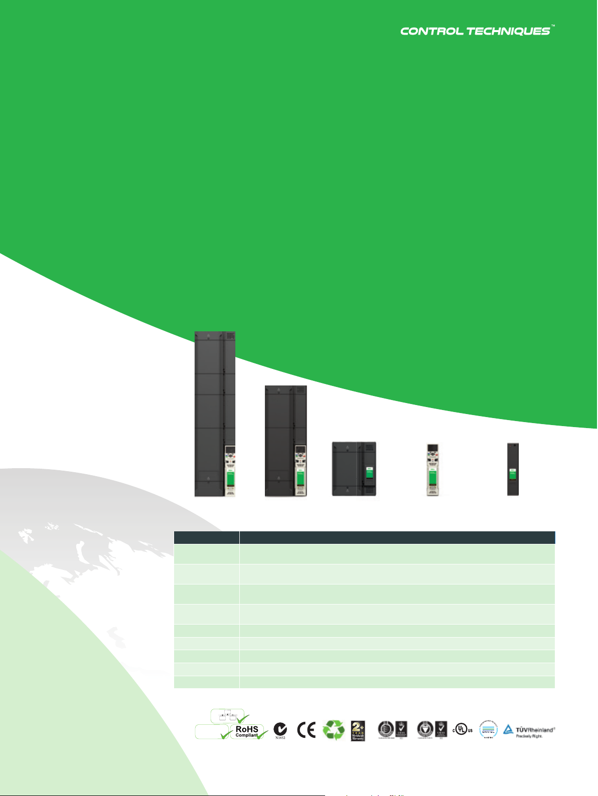
UNIDRIVE M SERIES
HIGH POWER MODULAR
AC DRIVES
M600/700/701/702
Highly reliable drive
modules allowing flexible
system design with
rapid global support
90 kW to 2.8 MW
125 hp to 4,200 hp
200 V | 400 V | 575 V | 690 V

SERVO DRIVE SERIES
UNIDRIVE M SERIES
Control
Techniques
Solving your
challenges
Nidec – the world’s No.1
comprehensive motor manufacturer
Nidec Corporation was founded in Kyoto, Japan in 1973
by four engineers. Today we have operations in over
40 countries through approximately 300 companies,
employing 110,000 people. Our vision has always
been to be the world’s number 1 for everything that
spins and moves. From small precision to supersized
motors; we create next-generation drive technology
that accommodates the needs of the society.
115,000
Employees worldwide
Control Techniques –
a global drives specialist
Control Techniques have been at the front of customerfocused drive technology for over 45 years. We’re
dedicated to the advancement of automation. From
product development at our headquarters to our 26
automation centers, we provide solutions relevant to the
industries in your region. We ensure high performance,
reliability and energy e ciency across every application.
1,500+
Employees worldwide
220 MANUFACTURING
LOCATIONS WORLDWIDE
Producing a comprehensive range of high quality
products, optimized for industry-specifi c customer
requirements
2
2
5 MANUFACTURING
LOCATIONS WORLDWIDE
Producing a comprehensive range of high quality
products, optimized for industry-specifi c customer
requirements
Unidrive M
High power modular drives
Unidrive M’s modular off ering provides a fl exible method of building
compact, reliable high-power solutions. Paralleled together, Unidrive M
can control asynchronous and permanent magnet motors in systems
up to 2.8 MW (4,200 hp). The frame 11 is a 250 kW (400 hp) module
that allows system builders to create high power solutions with the
smallest number of components, keeping both footprint and costs to
a minimum.
Unidrive M diff erentiates itself on performance with extremely fast current control
algorithms and high switching frequencies. Active Front End (AFE) solutions deliver
unparalleled torque precision and power quality.
The Unidrive M modules can be paralleled into a wide range of fl exible solutions to solve
all system needs including Active Front End and multi-pulse rectifi er confi gurations.
They can be controlled by M600, M700, M701 and M702 controllers.
DA, E, T
RECT..A,
RECT..T
Format
A AC in AC out module with integrated rectifi er and line choke. Available in frame size 9 and can be
E AC in AC out module with integrated rectifi er. Available in frame sizes 9, 10 & 11 and can be paralleled up
T AC in AC out module with 12 pulse integrated rectifi er. Available in frame size 9, 10 & 11 and can be
D DC in AC out module. Available in frame size 9, 10 & 11 and can be paralleled up to 2.8 MW (Unidrive
RECT..A AC in DC out rectifi er 6 pulse module (Unidrive SPMC replacement)
RECT..T AC in DC out rectifi er 12 pulse module (Unidrive SPMC2 replacement)
Standard Control M700, M701, M702, M600 controller for single module systems
Master Control M700, M701, M702, M600 master controller for systems with more than one module
Follower Control Follower controller for all paralleled modules
L
SI
Safety Integrity Level
paralleled up to 1.9 MW (Unidrive SPMA replacement)
to 2.8 MW
paralleled up to 2.8 MW
SPMD replacement)
Ethernet Onboard
3
Master control,
standard control
E171230
DRIVE SPECIALISTS SINCE 1973 3
DRIVE SPECIALISTS SINCE 1973 3
Follower
Control
UNIDRIVE M SERIES
Reliable and flexible
High performance solutions
Minimize downtime for critical operations
We know how important reliability is to our customers
and that every second of system downtime can
be costly. Unidrive M high power modules have
exceptional build quality based on over 45 years
of drive knowledge, expertise and development.
Built using world leading manufacturing processes,
the modules are packed with features proven to
keep Unidrive M running in the most testing of
environments. Control Techniques Automation Centres
are situated in many global regions to provide local
design consultation and rapid specialist technical
support wherever your business is located.
Reliability assured
• Every Unidrive M power module has been thoroughly tested in
environmental chambers that cycle a wide range of load and
thermal conditions
• PCBs have conformal coating to further increase resilience to
harsh environmental conditions
• Trip avoidance features take intelligent action instead of
interrupting critical processes.
For example:
– Active thermal monitoring reduces switching frequency as the
drive approaches thermal limits
– Load shedding reduces speed at current limits
– Supply loss ride-through keeps the drive running during
supply brown outs
• Protection alarms safeguard the wider system (e.g. over current,
over temperature, over voltage and short circuit protection)
• Intelligent variable speed fans ensure operating temperature
stays within limits. They are easily replaceable as part of routine
maintenance
• Wide supply voltage tolerance keeps drive operation smooth in
areas where supplies are variable
4
Create flexible systems easily
The modular approach to building high power systems
provides machine builders with flexibility while keeping
complexity low. Modules with integrated rectifiers and / or
line chokes can be easily paralleled keeping installation time
and component count to a minimum. Separate inverter and
rectifier modules (D, RECT..A and RECT..T) can be paralleled
into more flexible common DC bus and regenerative
configurations where power management and system
design eciency are key.
Flexible and easy system design:
• Unidrive M high power modules are designed to fit in
standard 600 mm deep x 400 mm wide (23.6 x 15.7 in)
cubicles
• 6,12,18 and 24 pulse input and Active Front End
configurations are easy to achieve
• Integrated cooling fan power supply means no
additional power supplies are required
• Output current ratings have been increased to use
fewer modules per system
• A common control interface ensures a consistent
programming method and feature set across the
whole Unidrive M range. Familiarity reduces the need
for training:
– Identical parameter structure with Smartcard
and SD card cloning support
– Connect software for monitoring, diagnostics
and parameter file management
– Machine Control Studio for application
programming in IEC61131-3 environment
– SI-Option module support for additional I/O and
fieldbus (e.g. Ethernet/IP, PROFINET RT, EtherCAT,
PROFIBUS)
– MCi and SI-Applications modules for advanced
application solutions
5DRIVE SPECIALISTS SINCE 1973

UNIDRIVE M SERIES
www.controltechniques.comwww.controltechniques.com
66
UNIDRIVE M SERIES
Make compact, easily
maintainable systems
• Unidrive M high power modules are incredibly
compact given the impressive amount of power
they can deliver. For example, the powerful AC in
AC out 250 kW (400 hp) module measures only
1242 x 310 x 312 mm (48.9 x 12.2 x 12.3 in) - a power
density unrivalled in the market place and almost
half the size of other leading suppliers.
• Overall system size and footprint is kept to a
minimum
• Manageable small and light modules are
maintained and replaced rapidly and easily
Reduce spares inventory
Unidrive M’s modular approach gives customers the
opportunity to standardize their solutions in order
to keep spares holding to a minimum as diff erent
systems can be serviced using one common spare.
Additionally, large volumes of standard product
modules are stocked at local distribution hubs in
convenient locations around the world meaning that
rapid delivery is always available to all customers.
Upgrade Unidrive SP modular
systems painlessly
Migration of Unidrive SP modular systems to
Unidrive M is fast and easy with many conversion
tools available:
• Parameter porting tools such as Connect and
Smartcard are available
• SyptPro can recompile SM-Applications programs
for SI-Applications and connect to existing CTNet
networks
• Identical width and depth dimensions, along with
retrofi t kits, mean that Unidrive M modules can
easily fi t into SP modular locations using existing
fi ttings
Environmental safety and
electrical conformance
• UL listed
• Electromagnetic immunity complies with
EN 61800-3 and EN 61000-6-2
• Electromagnetic emissions comply with
EN 61800-3
– On-board EMC fi lter, category C3
– Optional external EMC fi lter, category C2
depending on power rating
– Compliance with EN 61000-3-12 with
external line reactor
6
6

Create high performance solutions
Unidrive M delivers market leading control
performance at high powers with extremely
fast current control algorithms, advanced
thermal monitoring and high switching
frequencies. When Unidrive M power modules
are confi gured with an Active Front End,
dynamic torque response can be eff ectively
demanded across all power quadrants.
• Switching frequencies of up to 16 kHz in systems up to
160 kW (250 hp) and 8 kHz in systems up to 250 kW
(400 hp) allow Unidrive M to provide precision torque.
This is eff ective in demanding applications such as
test stands, where our ETPS solution (engine torque
pulsation system) can precisely simulate dynamic
engine torque profi les.
• Highly accurate thermal model ensures:
– High overload capability – 150% Heavy Duty
– Impressive low derating requirement in applications
that demand high torque at low speeds. Power
device temperature is intelligently managed
meaning smaller lower priced systems can be
specifi ed and product life is extended.
• Dynamic Active Front End confi gurations provide:
– Precision torque linearity across quadrants
– Corrective power factor operation (lagging,
unity or leading) for high quality power
– Harmonic mitigation
Dynamic response across 4 quadrants
SPEED
+
Forward
Regeneration
-
-
Forward
Motoring
+
TORQUE
Superb power quality management
400
300
200
100
0
0510 15 20
-100
Volts / Amps
-200
-300
-400
Power factor control
I
V
Example of a highly demanding
automotive test stand application
DC Bus
Ethernet
DRIVE SPECIALISTS SINCE 1973 77
7

UNIDRIVE M SERIES
Module configurations
and order information
‘A’, ‘E’ & ‘T’ – AC in AC out modules
Unidrive M’s AC in AC out modules are available in 3 frame sizes (9, 10, & 11) and
comprise an integrated 6 or 12 pulse rectifier with an inverter. ‘A’, ‘E’ and ‘T’ formats
can be paralleled together to reach powers of 2.8 MW (4,200 hp) and can be
supplied with an optional braking transistor. Frame 9 has an internal choke version
that can be paralleled to 1.9 MW (6 pulse only).
Example using ‘T’ format with 12 pulse rectier.
6 or 12 pulse integrated rectifier
Frames 9, 10, 11
(Frame 11 for
250 kW (400
hp) modules)
The above system is simply configured by ordering:
Component Quantity Part number
Size 9 parallel up
to 1.9 MW
(2,800 hp)
Size 10, 11 parallel up
to 2.8 MW
(4,200 hp)
‘T’ format power module (integrated
12 pulse rectifier with inverter)
Control standard In systems with only 1 ‘A’ ‘E’ or ‘T’ module, use 1 standard control M700-STANDARD00011100A0100
Control master In systems with >1 ‘A’ ‘E’ or ‘T’ module, use 1 master control M700-MASTER00011100A0100
Quantity of frame 11 modules required is: total power required /
250 kW – derating (see technical manual)
M000-114040640T10100AB100
Control follower
8
1 for each paralleled module (1 less than the total
number of modules)
M000-FOLLOWER00011100A0100

▲
‘D’ – DC in AC out modules
Example using ‘D’ format to parallel power
with RECT..A and RECT..T
Rectifiers
6 or 12 pulse rectifier
Unidrive M’s DC in AC out
modules are available in 3
frame sizes (9, 10, & 11) and
RECT..A or RECT..T
Size 10 or 11
(depending on
power requirement)
can be configured as either
output or active input stages
‘D’ inverter
Size 9, 10 or 11
D DD
of a system. ‘D’ modules can
be paralleled together using
(depending on
power requirement)
a common DC bus to reach
powers of 2.8 MW (4,200 hp).
The above system is simply configured by ordering:
Component Quantity Part number
Rectifier
RECT..A or RECT..T
size 10 or 11 depending on power
required
1 (add more as system power increases) RECT-114042x406T10100AB100
Size 9 - parallel up
to 1.9 MW (2,800
hp)
Size 10, 11 - parallel
up to 2.8 MW
(4,200 hp)
‘D’ format inverter module size 9, 10
or 11 depending on power required
Control standard In systems with only 1 ‘D’ inverter, use 1 standard control M700-STANDARD00011100A0100
Control master In systems with >1 ‘D’ inverter, use 1 master control M700-MASTER00011100A0100
Control follower
1 (add more as system power increases) M000-114040640D10100AB100
1 for each paralleled module (1 less than the total
number of modules)
M000-FOLLOWER00011100A0100
DRIVE SPECIALISTS SINCE 1973 9

UNIDRIVE M SERIES
Other fl exible con gurations with ‘D’ modules
RECT .. A
INPUT
COMPONENTS
RECT .. T
D +
STANDARD
control
D
+
STANDARD
control
DD
6 pulse input 12 pulse input Inverter regeneration mode
Frame 9: 90 to 110 kW / 125 to 150 hp HD
Frame 10: 132 to 160 kW / 200 to 250 hp HD
Frame 11: 185 to 250 kW / 300 to 400 hp HD
▲
RECT .. A RECT .. A
D
+ MASTER
control
D
+ FOLLOWER
controls
x 20 max
Paralleled inverters up
to 2.8 MW / 4,200 hp
10

Integrate, automate, communicate
with Unidrive M options
Unidrive M drives support a wide range of optional click-in System Integration (SI) modules that allow them
to integrate seamlessly with existing automation systems and other vendor supplied equipment. These include
communications, I/O, feedback devices, enhanced safety features and onboard PLCs.
Option Description
System Integration Modules
MCi200 Second processor, providing advanced machine control using Machine Control Studio.
MCi210 Adds to the MCi200 with a dual port Ethernet interface directly on the processor and additional I/O.
SI-Applications Second processor module, which allows SyPTPro application programs to be re-compiled for Unidrive M700.
SI-Safety An intelligent, programmable module to meet the IEC 61800-5-2/ISO 13849-1 functional safety standard up to SIL3/PLe.
SI-Ethernet Ethernet module supports EtherNet/IP and Modbus TCP/IP.
SI-EtherCAT EtherCAT interface module.
SI-PROFINET RT PROFINET RT interface module.
SI-PROFIBUS PROFIBUS interface module.
SI-CANopen CANopen interface module.
SI-DeviceNet DeviceNet interface module.
SI-Universal Encoder Encoder input and output interface supporting Quadrature, SinCos, HIPERFACE, EnDat and SSI encoders.
SI-Encoder Quadrature encoder input interface module.
SI-I/O Extended I/O interface module to increase the number of I/O analog and digital points on a drive.
Drive Interface Units
Smartcard Smartcard memory device to back-up and copy parameter sets and basic PLC programs.
SD Card Adaptor Allows an SD card to be inserted into the Smartcard slot, for parameter back-up cloning and application programs.
KI-485 Adaptor Allows the drive to communicate via RS485.
CT USB Comms cable The USB Comms cable allows the drive’s RS485 port to connect to a PC for use with Unidrive M’s PC tools.
Keypads
KI-Keypad
KI-Keypad RTC
Remote Keypad
Plain text, multilingual LCD keypad with up to 4 lines of text for in depth parameter and data descriptions,
for an enhanced user experience.
All the features of the KI-Keypad, but with battery operated real-time clock. This allows accurate time
stamping of events, aiding diagnostics.
Remote mountable, plain text, multi-language LCD keypad allows fl exible mounting on the outside of a
panel and meets IP66 (NEMA 4).
Remote keypad RTC
The keypad is remote mountable, allowing fl exible mounting on the outside of a panel (meets IP54/ NEMA 12).
Three line plain text, multi-language LCD keypad for rapid set-up and helpful diagnostics. Battery operated
real-time clock allows accurate time stamping of events, aiding diagnostics.
DRIVE SPECIALISTS SINCE 1973 11

SERVO DRIVE SERIES UNIDRIVE M SERIES
Unidrive M
frame sizes and ratings
INTEGRATED INVERTER & RECTIFIER
MODULAR DRIVES
Frame size 9A 9E | 9T 10E | 10T 11E | 11T
Frame sizes available M600 ➝ M700
Dimensions
(H x W x D)
Weight kg (lb) 66.5 (146.6) 46 (101.4) | 60 (132.3) 46 (101.4) | 60 (132.3) 63 (138.9) | 65 (143.3)
AC line choke
Max continuous heavy duty
kW rating / A rating
• • • •
mm 1049 x 310 x 290 1010 x 310 x 290 1010 x 310 x 290 1190 x 310 x 312
in 41.3 x 12.2 x 11.4 39.7 x 12.2 x 11.4 39.7 x 12.2 x 11.4 46.9 x 12.2 x 12.3
Internal
External
@ 200 V
@ 400 V
@ 575 V
@ 690 V
•
45 kW – 55 kW
(60 hp – 75 hp)
90 kW – 110 kW
(125 hp - 150 hp)
75 kW – 90 kW
(100 hp - 125 hp)
90 kW – 110 kW
(125 hp – 150 hp)
• • •
45 kW - 55 kW
(60 hp - 75 hp)
90 kW - 110 kW
(150hp)
75 kW - 90 kW
(100 hp - 125 hp)
90 kW - 110 kW
(125 hp - 150 hp)
75 kW - 90 kW
(100 hp - 125 hp)
132 kW - 160 kW
(200 hp - 250 hp)
110 kW - 132 kW
(150 hp - 200 hp)
132 kW - 160 kW
(175 hp - 200 hp)
N/A
185 kW - 250 kW
(300 hp - 400 hp)
150 kW - 225 kW
(200 hp - 300 hp)
185 kW - 250 kW
(250 hp - 300 hp)
Modular ratings up to 2.8 MW (4,200 hp) through parallel connected inverters.
12

DC-AC INVERTER RECTIFIER
Single, 6 pulse
Twin or 12
pulse for frame
9, 10 and 11
inverter
For frame
9 or 10
For frame 11
inverter
inverter
714 x 310 x 290 714 x 310 x 290 804 x 310 x 312 296 x 310 x 290 383 x 310 x 290 383 x 310 x 290
45 kW - 55 kW
(60 hp - 75 hp)
90 kW - 110 kW
(150hp)
75 kW - 90 kW
(100 hp - 125 hp)
90 kW - 110 kW
(125 hp - 150 hp)
(100 hp - 125 hp)
132 kW - 160 kW
(200 hp - 250 hp)
110 kW - 132 kW
(150 hp - 200 hp)
132 kW - 160 kW
(175 hp - 200 hp)
* Maximum DC output current
75 kW - 90 kW
N/A 413 A* N/A N /A
185 kW - 250 kW
(300 hp - 400 hp)
150 kW - 225 kW
(200 hp - 300 hp)
185 kW - 250 kW
(250 hp - 300 hp)
455 A* 689 A* 2 x 400 A*
246 A* 387 A*
251 A* 411 A*
2 x 380 A*
DRIVE SPECIALISTS SINCE 1973 13

SERVO DRIVE SERIES UNIDRIVE M SERIES
Hardware selection
90 to 250 kW / 150 to 400 hp
Unidrive M high power AC drives provide market-leading current ratings to
maximize system capability.
Heavy Duty Normal Duty
I
PEAK
Open
Loop
I PEAK
Rotor
Flux
Control
I CONT
MAX
Motor Shaft
Power I PEAK
Rectifier for
Modular ‘..D’
Inverters
‘-10204100A’
‘-10404520A’
INL401 INL411
INL402 INL412
INL401 INL411
INL402 INL412
Vac
±10%
200/240
380/480
M600
M700
M701
M702
‘-09201760’
‘-09202190’
‘-10202830’ 10..E/T/D 283 75 100 424 495 325 90 125 358
‘-10203000’ 10..E/T/D 300 90 125 450 525 360 110 150 396 OTL404 OTL414
‘-09402000’
‘-09402240’
‘-10402700’ 10..E/T/D 270 132 200 405 472 320 160 250 352
‘-10403200’ 10..E/T/D 320* 160 250 480 560 361 200 300 397 OTL404 OTL414
Order
Code
Frame &
Format
Identifiers
09..A/E/
09..A/E/
09..A/E/
09..A/E/
T/D
T/D
T/D
T/D
I CONT
MAX
176 45 60 264 308 216 55 75 238
219 55 75 328 383 266 75 100 293 OTL402 OTL412
200* 90 150 300 350 221 110 150 243
224* 110 150 336 392 266* 132 200 293 OTL402 OTL412
Motor
Shaft
Power
A kW hp A A A kW hp A RECT-..A/T Single Dual Single Dual
Input Choke Output Choke
OTL401 OTL411
OTL403 OTL413
OTL401 OTL411
OTL403 OTL413
500/575
500/690
‘-11403770’ 11..E/T/D 377* 185 300 566 659 437* 225 350 480
‘-11404170’ 11..E/T/D 417* 200 350 626 729 487* 250 400 535
‘-11404640’ 11..E/T/D 464* 250 400 696 812 507* 280 450 558 OTL407
‘-09501040’
‘-09501310’
‘-10501520’ 10..E/T/D 152 110 150 228 266 200 130 200 220
‘-10501900’ 10..E/T/D 190 132 200 285
‘-11502000’ 11..E/T/D 200* 150 200 300 350 248* 185 250 273
‘-11502540’ 11..E/T/D 254* 185 250 381 444 288* 225 300 317 OTL607
‘-11502850’ 11..E/T/D 285* 225 300 428 498 315* 250 350 346 OTL607
‘-09601040’
‘-09601310’
‘-10601500’ 10..E/T/D 150 132 175 225 262 172 160 200 189
‘-10601780’ 10..E/T/D 178 160 200 267 311 197 185 250 217 OTL604 OTL614
‘-11602100’ 11..E/T/D 210* 185 250 315 367 225* 200 250 248
‘-11602380’ 11..E/T/D 238* 200 250 357 416 275* 250 300 303 OTL607
‘-11602630’ 11..E/T/D 263* 250 300 394 460 305* 280 400 335 OTL607
09..A/E/
T/D
09..A/E/
T/D
09..A/E/
T/D
09..A/E/
T/D
104 75 100 156 182 125 110 125 138
131 90 125 196 229 150 110 150 165 OTL602 OTL612
332 200 150 200 220 OTL604 OTL614
104 90 125 156 182 125 110 150 138
131 110 150 196 229 155 132 175 171 OTL602 OTL612
‘-11406840A’
‘-1142X400T’
‘-10502430A’
‘-11503840A’
‘-1162X380T’
‘-10602480A’
‘-11604060A’
‘-1162X380T’
INL403L OTL405
INL403
INL601 INL611
INL602 INL612
INL603
INL601 INL611
INL602 INL612
INL603
OTL407
OTL601 OTL611
OTL603 OTL613
OTL605
OTL601 OTL611
OTL603 OTL613
OTL605
Notes:
* At 2 kHz switching frequency
For paralleling, a 5 % derating should be applied. For ratings at F
‘switching frequency’
Refer to electrical specification of the part number (page 15, digits 6-13)
14
> 3 kHz (or 2 kHz for F11) refer to User Guide

Range & Derivative
1 2 3 4 5
Digit:
Electrical Specification
Frame & Volts & Current
6 7
8
9 10 11 12 13
Drive Format Documentation Customer
Power Control
14
Spare
15
16
17
Code
18 19
Configure to
Order Optional
Build
24
Mxxx-
Drive Range Derivative Description
M600- Will control sensorless permanent
M700- Ethernet and 1 x STO
M701M702- Ethernet and 2 x STO
M000- Unassigned power – user fit control
RECT- Rectifier for modular range
HS70- High speed version of M700
HS71- High speed version of M701
HS72- High speed version of M702
10
Frame
Current Rating:
M100 to M702 - Heavy Duty rating x 10
RECT..T (twin rectifier) – 2 x Heavy Duty
rating
magnet and open loop
induction motors
Modbus and 1 x STO
4
Volts:
2 = 200 V
4 = 400 V
5 = 575 V
6 = 690 V
03200
A
1
0
Documentation:
0 = Supplied
separately
1 = English or
multilingual
2 = French
3 = Italian
4 = German
5 = Spanish
IP / NEMA Rating:
1 = IP20 / NEMA 1
Keypad:
0 = No Keypad on M6xx and M7xx
1
Control Module Range for
Unassigned Modular Drives
Mxxx-STANDARD011100A0100
Mxxx-MASTER00011100A0100
M000-FOLLOWER011100A0100
00
Brake Transistor:
B = Brake
N = N*
*Only available for
frame size 9 and up
A20B211220230
M000-
RECT-
Power
Ident.
A U
E U
T U
D U DC to AC Inverter
A 1 AC to DC Single Rectifier 10, 11
T 1 AC to DC Twin Rectifier 10, 11
Control
Ident.
Description Frame
Integrated Rectifier and Inverter
Internal Line Choke
Integrated Single Rectifier
and Inverter
External Line Choke
Integrated Twin Rectifier and
Inverter
External Line Choke
90 to 110 kW
125 to 150 hp
9
Up to 1.9 MW /
2,800 hp in Parallel
09,
90 to 250 kW
10, 11
125 to 400 hp
Up to 2.8 MW /
4,200 hp in Parallel
09,
10, 11
90 to 250 kW / 125
to 400 hp
Power Range
(Heavy Duty)
Access to
DRIVE SPECIALISTS SINCE 1973 15
DC bus
Yes
No
Yes
Yes

© 2018 Nidec Control Techniques Limited. The information contained in this brochure is for
guidance only and does not form part of any contract. The accuracy cannot be guaranteed as
Nidec Control Techniques Ltd have an ongoing process of development and reserve the right to
change the specifi cation of their products without notice.
Nidec Control Techniques Limited. Registered O ce: The Gro, Newtown, Powys SY16 3BE.
Registered in England and Wales. Company Reg. No. 01236886.
P.N. 0778-0092-05 08/18
 Loading...