


Control Getting Started
Guide
Unidrive M600
Universal Variable Speed AC drive for
induction and permanent magnet motors
Part Number: 0478-0240-02
Issue: 2

Contents
1 Safety information .......................................................................................3
1.1 Important safety information. Hazards. Competence of designers and installers ....3
1.2 Responsibility ...........................................................................................................3
1.3 Compliance with regulations ....................................................................................3
1.4 Electrical hazards .....................................................................................................4
1.5 Stored electrical charge ...........................................................................................4
1.6 Mechanical hazards .................................................................................................4
1.7 Access to equipment ................................................................................................4
1.8 Environmental limits ................................................................................................. 4
1.9 Hazardous environments .........................................................................................5
1.10 Motor ........................................................................................................................5
1.11 Mechanical brake control .........................................................................................5
1.12 Adjusting parameters ...............................................................................................5
1.13 Electromagnetic compatibility (EMC) .......................................................................5
2 Introduction ..................................................................................................6
2.1 Operating modes ......................................................................................................6
3 Control connections ....................................................................................8
3.1 Communications connections ..................................................................................8
3.2 Shield connections ................................................................................................... 9
3.3 Control connections ...............................................................................................10
4 Getting started ...........................................................................................11
4.1 Quick start commissioning / start-up using Unidrive M Connect
4.2 Keypad / display .....................................................................................................13
4.3 Keypad operation ...................................................................................................14
4.4 Menu 0 ...................................................................................................................15
4.5 Menu structure .......................................................................................................15
4.6 Advanced menus ...................................................................................................16
4.7 Changing the operating mode ................................................................................17
4.8 Saving parameters .................................................................................................17
4.9 Restoring parameter defaults .................................................................................18
4.10 Displaying parameters with non-default values only ..............................................18
4.11 Displaying destination parameters only .................................................................18
4.12 Parameter access level and security .....................................................................18
4.13 NV Media Card operation ....................................................................................... 19
4.14 Transferring data ....................................................................................................21
5 Basic parameters (Menu 0) .......................................................................22
5.1 Parameter descriptions ..........................................................................................25
6 Running the motor .....................................................................................30
6.1 Quick start connections ..........................................................................................30
6.2 Quick Start / start-up .............................................................................................32
7 Further information ...................................................................................41
7.1 Diagnostics .............................................................................................................41
(V02.00.00.00 onwards) .........................................................................................11
Unidrive M600 Control Getting Started Guide
Issue Number: 2

1 Safety information
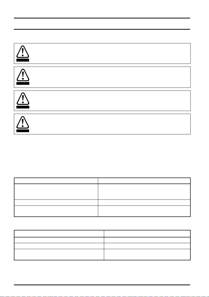
WARNING
CAUT ION
NOTE
1.1 Warnings, Cautions and Notes
A Warning contains information which is essential for avoiding a safety hazard.
A Caution contains information which is necessary for avoiding a risk of damage to the
product or other equipment.
A Note contains information, which helps to ensure correct operation of the product.
1.2 Important safety information. Hazards. Competence of designers and installers
This guide applies to products which control electric motors either directly (drives) or indirectly
(controllers, option modules and other auxiliary equipment and accessories). In all cases the hazards
associated with powerful electrical drives are present, and all safety information relating to drives and
associated equipment must be observed.
Specific warnings are given at the relevant places in this guide.
Drives and controllers are intended as components for professional incorporation into complete
systems. If installed incorrectly they may present a safety hazard. The drive uses high voltages and
currents, carries a high level of stored electrical energy, and is used to control equipment which can
cause injury. Close attention is required to the electrical installation and the system design to avoid
hazards either in normal operation or in the event of equipment malfunction. System design,
installation, commissioning/start-up and maintenance must be carried out by personnel who have the
necessary training and competence. They must read this safety information and this guide carefully.
1.3 Responsibility
It is the responsibility of the installer to ensure that the equipment is installed correctly with regard to
all instructions given in this guide. They must give due consideration to the safety of the complete
system, so as to avoid the risk of injury both in normal operation and in the event of a fault or of
reasonably foreseeable misuse.
The manufacturer accepts no liability for any consequences resulting from inappropriate, negligent or
incorrect installation of the equipment.
Safety information
Introduction Control connections Getting started
Basic parameters
(Menu 0)
Running the motor Further information
1.4 Compliance with regulations
The installer is responsible for complying with all relevant regulations, such as national wiring
regulations, accident prevention regulations and electromagnetic compatibility (EMC) regulations.
Particular attention must be given to the cross-sectional areas of conductors, the selection of fuses
or other protection, and protective ground (earth) connections.
This guide contains instructions for achieving compliance with specific EMC standards.
All machinery to be supplied within the European Union in which this product is used must comply
with the following directives:
2006/42/EC Safety of machinery.
2014/30/EU: Electromagnetic Compatibility.
Unidrive M600 Control Getting Started Guide 3
Issue Number: 2

1.5 Electrical hazards
The voltages used in the drive can cause severe electrical shock and/or burns, and could be lethal.
Extreme care is necessary at all times when working with or adjacent to the drive. Hazardous voltage
may be present in any of the following locations:
• AC and DC supply cables and connections
• Output cables and connections
• Many internal parts of the drive, and external option units
Unless otherwise indicated, control terminals are single insulated and must not be touched.
The supply must be disconnected by an approved electrical isolation device before gaining access to
the electrical connections.
The STOP and Safe Torque Off functions of the drive do not isolate dangerous voltages from the
output of the drive or from any external option unit.
The drive must be installed in accordance with the instructions given in this guide. Failure to observe
the instructions could result in a fire hazard.
1.6 Stored electrical charge
The drive contains capacitors that remain charged to a potentially lethal voltage after the AC supply
has been disconnected. If the drive has been energized, the AC supply must be isolated at least ten
minutes before work may continue.
1.7 Mechanical hazards
Careful consideration must be given to the functions of the drive or controller which might result in a
hazard, either through their intended behaviour or through incorrect operation due to a fault. In any
application where a malfunction of the drive or its control system could lead to or allow damage, loss
or injury, a risk analysis must be carried out, and where necessary, further measures taken to reduce
the risk - for example, an over-speed protection device in case of failure of the speed control, or a
fail-safe mechanical brake in case of loss of motor braking.
With the sole exception of the Safe Torque Off function, none of the drive functions must be
used to ensure safety of personnel, i.e. they must not be used for safety-related functions.
The Safe Torque Off function may be used in a safety-related application. The system designer is
responsible for ensuring that the complete system is safe and designed correctly according to the
relevant safety standards.
The design of safety-related control systems must only be done by personnel with the required
training and experience. The Safe Torque Off function will only ensure the safety of a machine if it is
correctly incorporated into a complete safety system. The system must be subject to a risk
assessment to confirm that the residual risk of an unsafe event is at an acceptable level for the
application.
1.8 Access to equipment
Access must be restricted to authorized personnel only. Safety regulations which apply at the place
of use must be complied with.
1.9 Environmental limits
Instructions in this guide regarding transport, storage, installation and use of the equipment must be
complied with, including the specified environmental limits. This includes temperature, humidity,
contamination, shock and vibration. Drives must not be subjected to excessive physical force.
4 Unidrive M600 Control Getting Started Guide
Issue Number: 2

1.10 Hazardous environments
The equipment must not be installed in a hazardous environment (i.e. a potentially explosive
environment).
1.11 Motor
The safety of the motor under variable speed conditions must be ensured.
To avoid the risk of physical injury, do not exceed the maximum specified speed of the motor.
Low speeds may cause the motor to overheat because the cooling fan becomes less effective,
causing a fire hazard. The motor should be installed with a protection thermistor. If necessary, an
electric forced vent fan should be used.
The values of the motor parameters set in the drive affect the protection of the motor. The default
values in the drive must not be relied upon. It is essential that the correct value is entered in the
Motor Rated Current parameter.
1.12 Mechanical brake control
Any brake control functions are provided to allow well co-ordinated operation of an external brake
with the drive. While both hardware and software are designed to high standards of quality and
robustness, they are not intended for use as safety functions, i.e. where a fault or failure would result
in a risk of injury. In any application where the incorrect operation of the brake release mechanism
could result in injury, independent protection devices of proven integrity must also be incorporated.
1.13 Adjusting parameters
Some parameters have a profound effect on the operation of the drive. They must not be altered
without careful consideration of the impact on the controlled system. Measures must be taken to
prevent unwanted changes due to error or tampering.
1.14 Electromagnetic compatibility (EMC)
Installation instructions for a range of EMC environments are provided in the relevant Power
Installation Guide. If the installation is poorly designed or other equipment does not comply with
suitable standards for EMC, the product might cause or suffer from disturbance due to
electromagnetic interaction with other equipment. It is the responsibility of the installer to ensure that
the equipment or system into which the product is incorporated complies with the relevant EMC
legislation in the place of use.
Safety information
Introduction Control connections Getting started
Basic parameters
(Menu 0)
Unidrive M600 Control Getting Started Guide 5
Issue Number: 2
Running the motor Further information

2Introduction
High performance drive for induction and sensorless permanent magnet motors
Unidrive M600 delivers maximum machine performance with sensorless induction and sensorless
permanent magnet motor control, for dynamic and efficient machine operation. An optional encoder
module can be used for precise closed loop induction motor control with quadrature encoders and
digital lock / frequency following.
Features
• Universal high performance drive for induction and sensorless permanent magnet motors.
• Onboard IEC 61131-3 programmable automation
• NV Media Card for parameter copying and data storage
• 485 serial communications interface
• Single channel Safe Torque Off (STO) input
Optional features
• Select up to three option modules
2.1 Operating modes
The drive is designed to operate in any of the following modes:
1. Open loop mode
Open loop vector mode
Fixed V/F mode (V/Hz)
Quadratic V/F mode (V/Hz)
2. RFC - A
With position feedback sensor (requires optional SI-Encoder module)
Without position feedback sensor (Sensorless)
3. RFC - S
Without position feedback sensor (Sensorless)
2.1.1 Open loop mode
The drive applies power to the motor at frequencies varied by the user. The motor speed is a result of
the output frequency of the drive and slip due to the mechanical load. The drive can improve the
speed control of the motor by applying slip compensation. The performance at low speed depends
on whether V/F mode or open loop vector mode is selected.
Open loop vector mode
The voltage applied to the motor is directly proportional to the frequency except at low speed where
the drive uses motor parameters to apply the correct voltage to keep the flux constant under varying
load conditions.
Typically 100 % torque is available down to 1 Hz for a 50 Hz motor.
Fixed V/F mode
The voltage applied to the motor is directly proportional to the frequency except at low speed where a
voltage boost is provided which is set by the user. This mode can be used for multi-motor
applications.
Typically 100 % torque is available down to 4 Hz for a 50 Hz motor.
6 Unidrive M600 Control Getting Started Guide
Issue Number: 2

Quadratic V/F mode
The voltage applied to the motor is directly proportional to the square of the frequency except at low
speed where a voltage boost is provided which is set by the user. This mode can be used for running
fan or pump applications with quadratic load characteristics or for multi-motor applications. This
mode is not suitable for applications requiring a high starting torque.
2.1.2 RFC-A mode
Rotor Flux Control for Asynchronous (induction) motors (RFC-A) encompasses closed loop vector
control with and without a position feedback device.
With position feedback (requires optional SI-Encoder module)
For use with induction motors with a feedback device installed. The drive directly controls the speed
of the motor using the feedback device to ensure the rotor speed is exactly as demanded. Motor flux
is accurately controlled at all times to provide full torque all the way down to zero speed.
Safety information
Introduction
Without position feedback (Sensorless)
Sensorless mode provides closed loop control without the need for position feedback by using
current, voltages and key operating motor parameters
to estimate the motor speed. It can eliminate instability traditionally associated with open loop control
such as operating large motors with light loads at low frequencies.
2.1.3 RFC- S
Rotor Flux Control for Synchronous (permanent magnet brushless) motors (RFC-S) provides closed
loop control without a position feedback device.
Without position feedback
For use with permanent magnet brushless motors without a feedback device installed.
Flux control is not required because the motor is self excited by the permanent magnets which form
part of the rotor.
Full torque is available all the way down to zero speed, with salient motors.
Control connections Getting started
Basic parameters
(Menu 0)
Running the motor Further information
Unidrive M600 Control Getting Started Guide 7
Issue Number: 2
3 Control connections
1 1
8
8
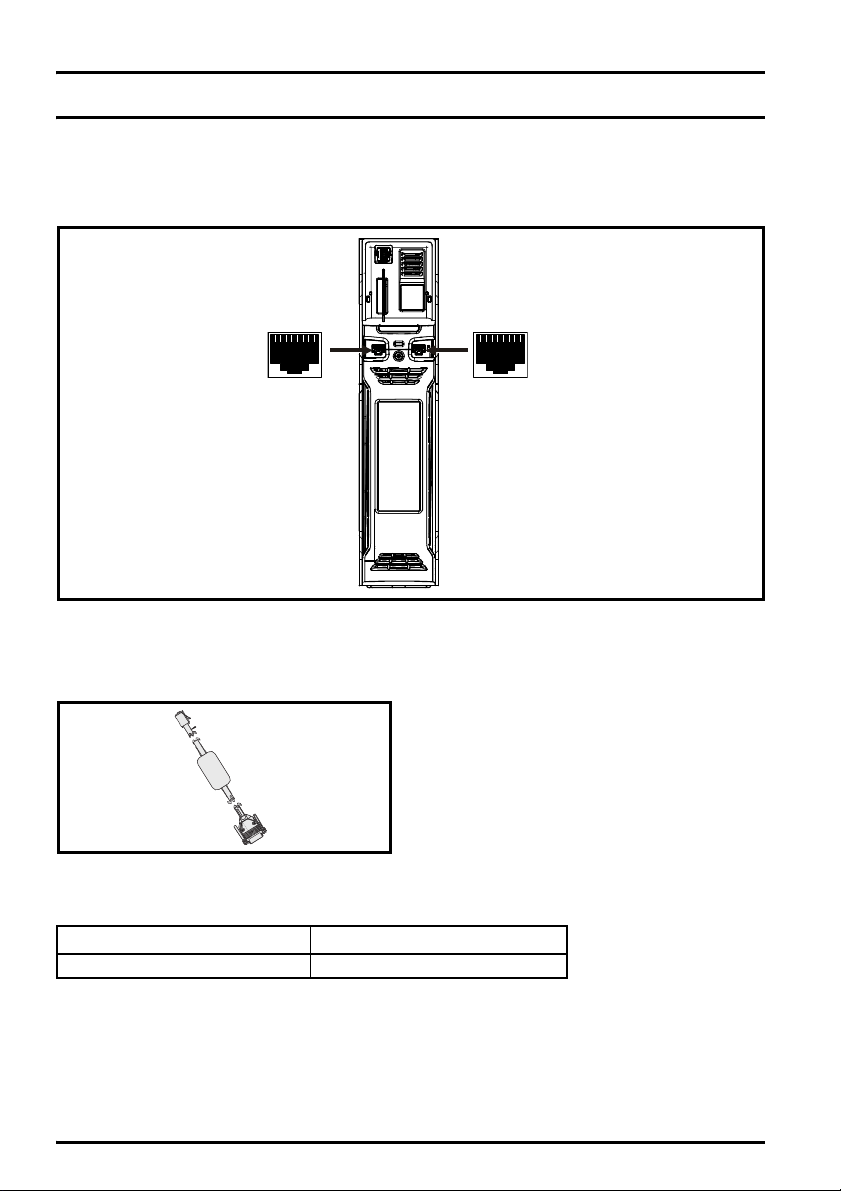
3.1 Communications connections
The drive offers a 2 wire 485 serial interface. This enables the drive set-up, operation and monitoring
to be carried out with a PC or controller if required.
Figure 3-1 Location of the communication connectors
3.1.1 485 Serial communications
The drive provides two parallel RJ45 connectors allowing easy daisy chaining. The drive supports
the Modbus RTU protocol. See Table 3-2 for the connection details.
Figure 3-2 Isolated serial comms lead
An isolated serial communications lead has been designed to connect the drive to IT equipment
(such as laptop computers), and is available from the supplier of the drive. See below for details:
Table 3-1 Isolated serial comms lead details
The “isolated serial communications” lead has reinforced insulation as defined in IEC60950 for
altitudes up to 3,000 m.
Part number Description
4500-0096 CT USB Comms cable
8 Unidrive M600 Control Getting Started Guide
Issue Number: 2

Table 3-2 Serial communication port pin-outs
Pin Function
1 120 Ω Termination resistor
2RX TX
3 Isolated 0 V
4 +24 V (100 mA)
5 Isolated 0 V
6 TX enable
7RX\ TX\
8
RX\ TX\ (if termination resistors are required, link to pin 1)
Shell Isolated 0 V
3.2 Shield connections
The following guidelines should be followed to ensure suppression of radio-frequency
emission and good noise immunity. It is particularly recommended that the guidelines for the
encoder cable be followed closely in order to avoid disturbance to the encoder operation from
electrical noise. Use the grounding bracket and grounding clamp supplied with the drive to terminate
the shields at the drive.
Figure 3-3 Grounding of signal cable shields using the grounding bracket
Safety information Introduction
Control connections
Getting started
Motor cable: Use a motor cable with an overall shield. Connect the shield of the motor cable to the
ground terminal of the motor frame using a link that is as short as possible and not exceeding 50 mm
(2 in) long. A full 360 ° termination of the shield to the terminal housing of the motor is beneficial.
Encoder cable: For best shielding (when using an SI-Encoder option module), use cable with an
overall shield and individual shields on twisted pairs, connect the cable as illustrated in Figure 3-4.
Clamp the overall shield to grounded metallic surfaces at both the encoder and the drive.
Brake resistor cable: The optional braking resistor should also be wired with shielded cable. If
unshielded wire is required refer to the Control User Guide for guidance.
Unidrive M600 Control Getting Started Guide 9
Issue Number: 2
Basic parameters
(Menu 0)
Running the motor Further information

Control cables: If the control wiring is to leave the enclosure, it must be shielded and the shield(s)
Cable
Cable
shield
Twis ted
pair
shield
Cable
shield
Twis ted
pair
shield
Connection
at motor
Connection
at drive
Ground clamp
on shield
Shield
connection
to 0V
Shield
connection
to 0V
clamped to the drive using the grounding bracket. Remove the outer insulating cover of the cable to
ensure the shield(s) make contact with the bracket, but keep the shield(s) intact until as close as
possible to the terminals.
Figure 3-4 Feedback cable shield connections
3.3 Control connections
For information on control connections, refer to the back cover of this guide.
10 Unidrive M600 Control Getting Started Guide
Issue Number: 2
4 Getting started
4.1 Quick start commissioning / start-up using Unidrive M Connect (V02.00.00.00 onwards)
Unidrive M Connect is a Windows™ based software commissioning / start-up tool for Unidrive M. Unidrive
M Connect can be used for commissioning / start-up and monitoring, drive parameters can be uploaded,
downloaded and compared and simple or custom menu listings can be created. Drive menus can be
displayed in standard list format or as live block diagrams. Unidrive M Connect is able to communicate with
a single drive or a network. Unidrive M Connect can be downloaded from www.controltechniques.com (file
size approximately 100 MB).
Unidrive M Connect system requirements
• Windows 8, Windows 7 SP1, Windows Vista SP2, Windows XP SP3
• Minimum of 1280 x 1024 screen resolution with 256 colours
• Microsoft.Net Frameworks 4.0 (this is provided in the downloaded file)
• Note that you must have administrator rights to install Unidrive M Connect
Any previous copy of Unidrive M Connect should be uninstalled before proceeding with the installation
(existing projects will not be lost). Included within Unidrive M Connect is the Parameter Reference Guide for
Unidrive M600.
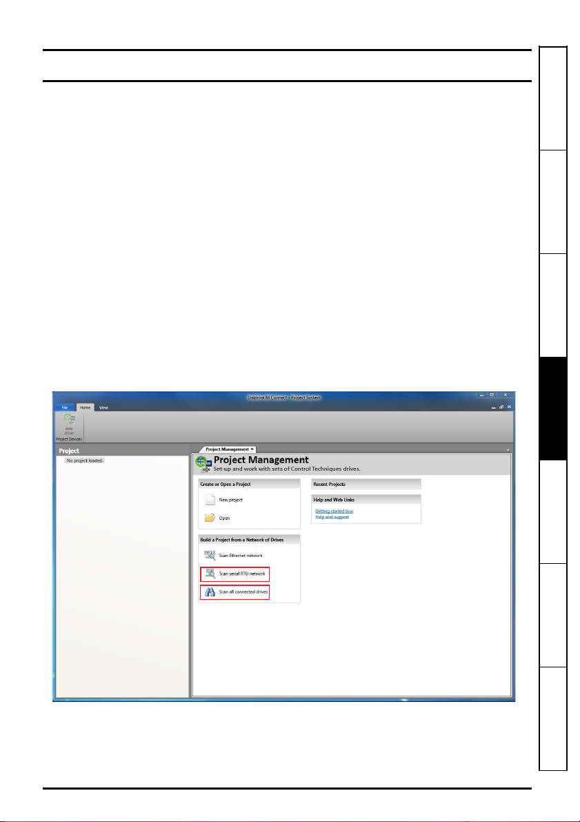
4.1.1 Power-up the drive
1. Start Unidrive M Connect, and on the ‘Project Management’ screen select 'Scan serial RTU network' or
'Scan all connected drives’.
Safety information Introduction Control connections
Getting started
Unidrive M600 Control Getting Started Guide 11
Issue Number: 2
Basic parameters
(Menu 0)
Running the motor Further information

Select the discovered drive.
1
2
4
3
1. Select the ‘Online’ icon to connect with the drive. When a successful connection is made the icon will
be highlighted orange.
2. Select ‘Set mode and region’.
If the required control mode is highlighted in the ‘Drive Settings’ dialog, then:
• Change the supply frequency, if required and select ‘Apply’, otherwise select ‘Cancel’.
• Select ‘Default parameters‘ from the Dashboard and in the ‘Default Parameters’ dialogue, select ‘Apply’
If the required control mode is not highlighted in the ‘Drive Settings’ dialog then:
• Select the required mode and supply frequency.
• Select ‘Apply’.
3. Select ‘Setup’ and perform the steps highlighted (dotted lines indicate a step which may not need to be
performed.
Action Detail
Unidrive M Connect contains a database for induction motors and permanent magnet motors.
Motor Setup
Analog I/O
Ramps Setup
Autotune
Provision is also made to enter motor nameplate data.
The next section describes the use of the motor database for a Leroy Somer LSRPM motor
used in RFC-S Sensorless mode.
The motor thermistor can be selected in Pr 07.015. Refer to the parameter help for Pr 07.015
for further information.
Enter the required Acceleration rate and Deceleration rate
Note: If a braking resistor is installed, set 'Ramp mode' to 'Fast'. Also ensure Pr 10.030 and
Pr 10.031 and Pr 10.061 are set correctly, otherwise premature 'Brake R Too Hot' trips may
be seen).
Not required when using data from the motor database for a Leroy Somer LSRPM motor used
in RFC-S Sensorless mode.
4. Select 'Save parameters in drive' to perform a parameter save.
The drive is now ready to run.
12 Unidrive M600 Control Getting Started Guide
Issue Number: 2

4.2 Keypad / display
NOTE
4.2.1 Understanding the display
The keypad can only be mounted on the drive.
4.2.2 KI-Keypad
The KI-Keypad display consists of two rows of text. The upper row shows the drive status or the
menu and parameter number currently being viewed. The lower row of the display line shows the
parameter value or the specific trip type. The last two characters on the first row may display special
indications. If more than one of these indications is active then the indications are prioritized as
shown in Table 4-1 .
When the drive is powered up the lower row will show the power up parameter defined by Parameter
Displayed At Power-up (11.022).
Figure 4-1 KI-Keypad
1. Escape button
2. Start reverse (Auxiliary button)
3. Start forward
4. Navigation keys (x4)
5. Stop / Reset (red) button
6. Enter button
The red stop button is also used to reset the drive.
Table 4-1 Active action icon
Active action icon Description
Row
(1=top)
Priority
in row
Safety information Introduction Control connections
Getting started
Basic parameters
(Menu 0)
Accessing non-volatile media card 1 1
Alarm active 1 2
Keypad real-time clock battery low 1 3
or
Drive security active and locked or
unlocked
14
Motor map 2 active 2 1
User program running 3 1
Keypad reference active 4 1
Unidrive M600 Control Getting Started Guide 13
Issue Number: 2
Running the motor Further information

4.3 Keypad operation
To enter Edit Mode,
press key,
Status
Mode
Parameter
Mode
Edit Mode
(Character to be edited in lower line of display flashing)
Change parameter values
using keys.
When returning
to Parameter
Mode use the
keys to select
another parameter
to change, if
required
To enter Parameter
Mode, press key or
Temporary
Parameter
Mode
Timeout
Timeout
To return to Status Mode,
RO
parameter
R/W
parameter
To select parameter
Press
is displayed)
To return to Parameter Mode,
Press key to keep the new parameter value
Press key to ignore the new parameter value and return
the parameter to the pre-edited value
Press key
Timeout
or
Press key
(
4.3.1 Control buttons
The keypad consists of:
• Navigation Keys - Used to navigate the parameter structure and change parameter values.
• Enter / Mode button - Used to toggle between parameter edit and view mode.
• Escape / Exit button - Used to exit from parameter edit or view mode. In parameter edit mode, if
parameter values are edited and the exit button pressed the parameter value will be restored to
the value it had on entry to edit mode.
• Start forward button - Use to provide a 'Run' command if keypad mode is selected.
• Start reverse button - Used to control the drive if keypad mode is selected and the reverse button
is activated.
• Stop / Reset button - Used to reset the drive. In keypad mode can be used for 'Stop'.
Figure 4-2 Display modes
The navigation keys can only be used to move between menus if Pr 00.049 has been set to show 'All
Menus'
14 Unidrive M600 Control Getting Started Guide
Issue Number: 2
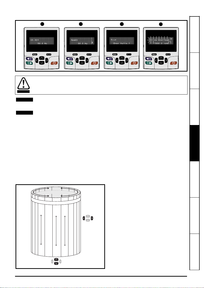
Figure 4-3 Mode examples
12
34
WARNING
NOTE
NOTE
Menu 0
....MM.000....
00.050
00.049
00.048
00.047
00.046
00.001
00.002
00.003
00.004
00.005
Moves
between
parameters
Menu 41
Menu 1
Menu 2
Moves between Menus
41.029
41.028
41.027
41.026
41.025
41.001
41.002
41.003
41.004
41.005
01.001
01.002
01.003
01.004
01.005
01.050
01.049
01.048
01.047
01.046
Option module menus (S.mm.ppp)*
Do not change parameter values without careful consideration; incorrect values may
cause damage or a safety hazard.
When changing the values of parameters, make a note of the new values in case they
need to be entered again.
For new parameter-values to apply after the AC supply to the drive is interrupted, new
values must be saved. Refer to section 4.8 Saving parameters on page 17.
4.4 Menu 0
Menu 0 is used to bring together various commonly used parameters for basic easy set up of the
drive. Appropriate parameters are copied from the advanced menus into menu 0 and thus exist in
both locations. For further information, refer to Chapter 5 Basic parameters (Menu 0) on page 22.
4.5 Menu structure
The drive parameter structure consists of menus and parameters. The drive initially powers up so
that only Menu 0 can be viewed. The up and down arrow buttons are used to navigate between
parameters and once Pr 00.049 has been set to 'All Menus' the left and right buttons are used to
navigate between menus. For further information, refer to section 4.12 Parameter access level and
security on page 18.
Safety information Introduction Control connections
Getting started
Basic parameters
(Menu 0)
Figure 4-4 Menu structure
The menus and parameters roll over in both
directions. i.e. if the last parameter is
displayed, a further press will cause the
display to rollover and show the first
parameter.
When changing between menus the drive
remembers which parameter was last
viewed in a particular menu and thus
displays that parameter.
* The option module menus (S.mm.ppp) are
only displayed if option modules are
installed. Where S signifies the option
module slot number and the mm.ppp
signifies the menu and the parameter
number of the option module's internal
menus and parameter.
Unidrive M600 Control Getting Started Guide 15
Issue Number: 2
Running the motor Further information

4.6 Advanced menus
The advanced menus consist of groups or parameters appropriate to a specific function or feature of
the drive. Menus 0 to 41 can be viewed on the KI-Keypad.
Table 4-2 Advanced menu descriptions
Menu Description
0 Commonly used basic set-up parameters for quick / easy programming
1 Frequency / speed reference
2Ramps
3 Frequency slaving and speed control
4 Torque and current control
5 Motor control
6 Sequencer and clock
7 Analog I/O, Temperature monitoring
8 Digital I/O
9 Programmable logic, motorized pot, binary sum, timers and scope
10 Status and trips
11 Drive set-up and identification, serial communications
12 Threshold detectors and variable selectors
13 Standard motion control
14 User PID controller
15 Option module slot 1 set-up menu
16 Option module slot 2 set-up menu
17 Option module slot 3 set-up menu
18 General option module application menu 1
19 General option module application menu 2
20 General option module application menu 3
21 Second motor parameters
22 Menu 0 set-up
23 Not allocated
28 Not allocated
29 Reserved menu
30 Onboard user programming application menu
Slot 1 Slot 1 option menus*
Slot 2 Slot 2 option menus*
Slot 3 Slot 3 option menus*
* Only displayed when the option modules are installed.
16 Unidrive M600 Control Getting Started Guide
Issue Number: 2
4.7 Changing the operating mode
NOTE
Changing the operating mode returns all parameters to their default value, including the motor
parameters. User security status (00.049) and User security code (00.034) are not affected by this
procedure).
Procedure
Use the following procedure only if a different operating mode is required:
1. Ensure the drive is not enabled, i.e. terminal 31 is open or Pr 06.015 is OFF (0)
2. Enter either of the following values in Pr mm.000, as appropriate:
1253 (50Hz AC supply frequency)
1254 (60Hz AC supply frequency)
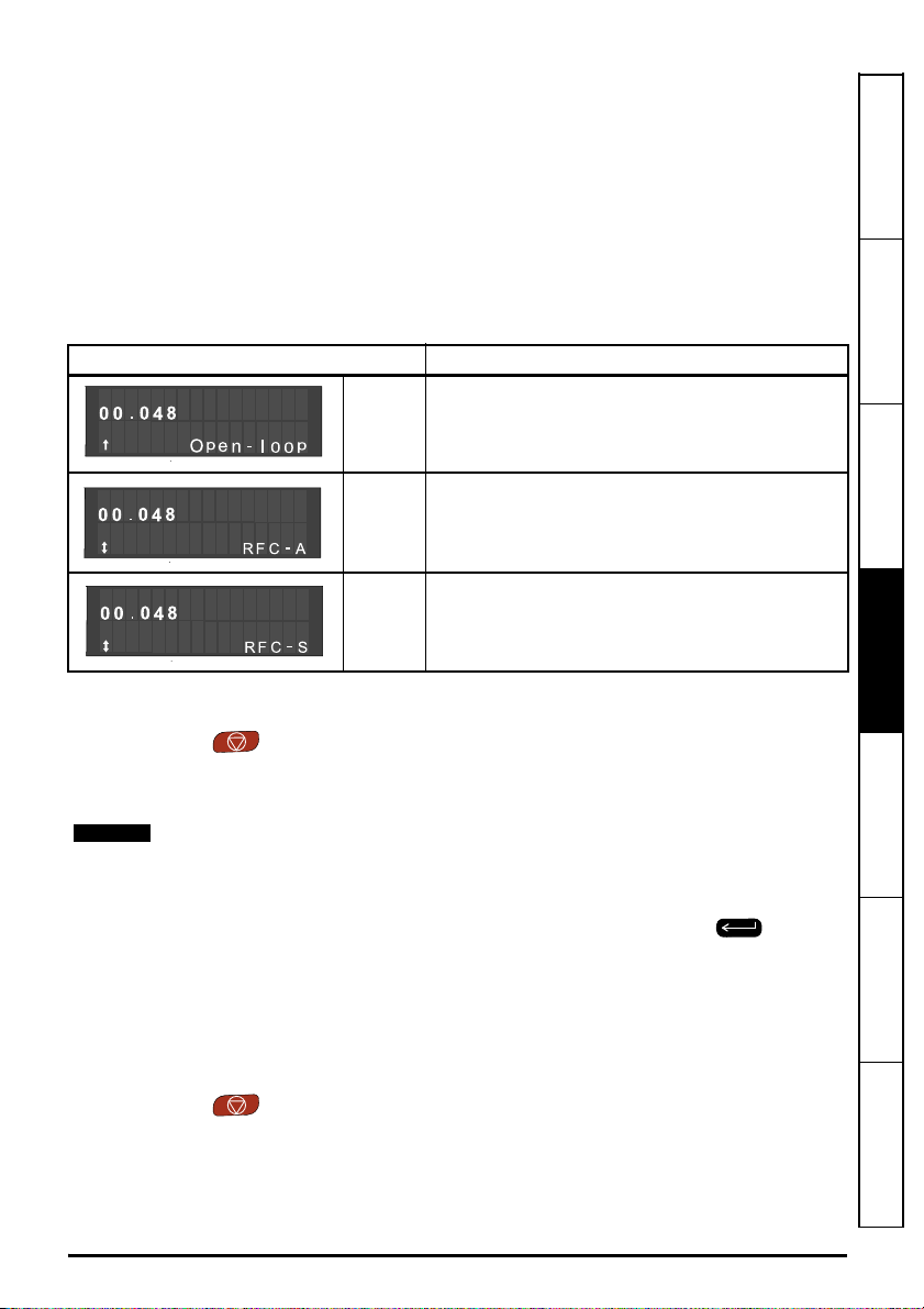
3. Change the setting of Pr 00.048 as follows:
Pr 00.048 setting Operating mode
Safety information Introduction Control connections
1
2
(Induction motor with or without position feedback)
3
The figures in the second column apply when serial communications are used.
4. Either:
• Press the red reset button
• Toggle the reset digital input
• Carry out a drive reset through serial communications by setting Pr 10.038 to 100.
Entering 1253 or 1254 in Pr mm.000 will only load defaults if the setting of Pr 00.048 has
been changed.
(Permanent magnet motor without position
Open-loop
(Induction motor)
RFC-A
RFC-S
feedback)
4.8 Saving parameters
When changing a parameter in Menu 0, the new value is saved when pressing the Enter
button to return to parameter view mode from parameter edit mode.
If parameters have been changed in the advanced menus, then the change will not be saved
automatically. A save function must be carried out.
Procedure
1. Select ‘Save Parameters'* in Pr mm.000 (alternatively enter a value of 1000* in Pr mm.000)
2. Either:
• Press the red reset button
• Toggle the reset digital input, or
• Carry out a drive reset through serial communications by setting Pr 10.038 to 100
* If the drive is in the under voltage state (i.e. when the control terminal 1 & 2 are being supplied from
a low voltage DC supply) a value of 1001 must be entered into Pr
mm.000
to perform a save function.
Getting started
Basic parameters
(Menu 0)
Running the motor Further information
Unidrive M600 Control Getting Started Guide 17
Issue Number: 2

4.9 Restoring parameter defaults
Restoring parameter defaults by this method saves the default values in the drives memory. User
security status (00.049) and User security code (00.034) are not affected by this procedure).
Procedure
1. Ensure the drive is not enabled, i.e. terminal 31 is open or Pr 06.015 is OFF (0)
2. Select 'Reset 50 Hz Defs' or 'Reset 60 Hz Defs' in Pr mm.000. (alternatively, enter 1233 (50 Hz
settings) or 1244 (60 Hz settings) in Pr mm.000).
3. Either:
• Press the red reset button
• Toggle the reset digital input
• Carry out a drive reset through serial communications by setting Pr 10.038 to 100
4.10 Displaying parameters with non-default values only
By selecting 'Show non-default' in Pr mm.000 (Alternatively, enter 12000 in Pr mm.000), the only
parameters that will be visible to the user will be those containing a non-default value. This function
does not require a drive reset to become active. In order to deactivate this function, return to
Pr mm.000 and select 'No action' (alternatively enter a value of 0). Please note that this function can
be affected by the access level enabled, refer to section 4.12 Parameter access level and security on
page 18 for further information regarding access level.
4.11 Displaying destination parameters only
By selecting 'Destinations' in Pr mm.000 (Alternatively enter 12001 in Pr mm.000), the only
parameters that will be visible to the user will be destination parameters. This function does not
require a drive reset to become active. In order to deactivate this function, return to Pr mm.000 and
select 'No action' (alternatively enter a value of 0).
Please note that this function can be affected by the access level enabled, refer to section
4.12 Parameter access level and security for further information regarding access level.
4.12 Parameter access level and security
The parameter access level determines whether the user has access to Menu 0 only or to all the
advanced menus (Menus 1 to 41) in addition to Menu 0. The User Security determines whether the
access to the user is read only or read write. Both the User Security and Parameter Access Level
can operate independently of each other as shown in Table 4-3.
Table 4-3 Parameter access level and security
User security
status (11.044)
0 Menu 0
1 All Menus
2 Read-only Menu 0
3 Read-only
4 Status only
5 No access
The default settings of the drive are Parameter Access Level Menu 0 and User Security Open i.e.
read / write access to Menu 0 with the advanced menus not visible.
Access level User security Menu 0 status
Open RW Not visible
Closed RO Not visible
Open RW RW
Closed RO RO
Open RO Not visible
Closed RO Not visible
Open RO RO
Closed RO RO
Open Not visible Not visible
Closed Not visible Not visible
Open Not visible Not visible
Closed Not visible Not visible
Advanced menu
status
18 Unidrive M600 Control Getting Started Guide
Issue Number: 2

4.13 NV Media Card operation
4.13.1 Introduction
The Non-Volatile Media Card feature enables simple configuration of parameters, parameter back-up
and drive cloning using a SMARTCARD or SD card. The drive offers backward compatibility for a
Unidrive SP SMARTCARD.
The NV Media Card can be used for:
• Parameter copying between drives
• Saving drive parameter sets
• Saving a program
The NV Media Card is located at the top of the module under the drive display (if installed) on the lefthand side.
Ensure NV Media Card is inserted with the contacts facing the left-hand side of the drive.
The drive only communicates with the NV Media Card when commanded to read or write, meaning
the card may be "hot swapped".
Figure 4-5 Installation of the NV Media Card
Safety information Introduction Control connections
Getting started
1. Installing the NV Media Card
2. NV Media Card installed
NV Media Card Part number
SD Card Adaptor (memory card not included) 3130-1212-03
8 kB SMARTCARD 2214-4246-03
64 kB SMARTCARD 2214-1006-03
Unidrive M600 Control Getting Started Guide 19
Issue Number: 2
Basic parameters
(Menu 0)
Running the motor Further information

4.13.2 NV Media Card support
Pr = Read +00.030
Drive reads all
parameters from
the NV Media Card
Pr = Program +00.030
Programs all drive
parameters to the
NV Media Card
NOTE
Overwrites any
data already in
data block 1
Pr =Auto +00.030
Auto
Save
Drive automatically
writes to the
Media Card
when a parameter
save is performed
Pr = Boot +00.030
Boot
Auto Save
Drive boots from the
NV Media Card on
power up and
automatically writes
to the Media Card
when a parameter
save is performed
The NV Media Card can be used to store drive parameters and / or PLC programs set from the
Unidrive M in data blocks 001 to 499.
The Unidrive M is compatible with a Unidrive SP SMARTCARD and is able to read and translate the
Unidrive SP parameter set into a compatible parameter set for Unidrive M. This is only possible if the
Unidrive SP parameter set was transferred to the SMARTCARD using the difference from defaults
transfer method (i.e. 4yyy transfer). The Unidrive M is not able to read any other type of Unidrive SP
data block on the card. Although it is possible to transfer difference from default data blocks from a
Unidrive SP into the Unidrive M, the following should be noted:
1. If a parameter from the source drive does not exist in the target drive then no data is transferred
for that parameter.
2. If the data for the parameter in the target drive is out of range then the data is limited to the range
of the target parameter.
3. If the target drive has a different rating to the source drive then the normal rules for this type of
transfer apply.
Figure 4-6 Basic NV Media Card operation
The whole card may be protected from writing or erasing by setting the read-only flag, refer to the
Control User Guide for further information.
The card should not be removed during data transfer, as the drive will produce a trip. If this occurs
then either the transfer should be reattempted or in the case of a card to drive transfer, default
parameters should be loaded.
20 Unidrive M600 Control Getting Started Guide
Issue Number: 2

4.14 Transferring data
Data transfer, erasing and protecting the information is performed by entering a code in Pr mm.000
and then resetting the drive as shown in Table 4-4.
Table 4-4 SMARTCARD and SD card codes
Code Operation SMARTCARD SD card
2001
4yyy
5yyy
6yyy
7yyy Erase file yyy. 99
8yyy
9555 Clear the warning suppression flag 99
9666 Set the warning suppression flag 99
9777 Clear the read-only flag 99
9888 Set the read-only flag 99
9999 Erase and format the NV media card 99
15yyy
16yyy As 15yyy, but for slot 2 9
17yyy As 15yyy, but for slot 3 9
18yyy
19yyy As 18yyy, but for slot 2 9
20yyy As 18yyy, but for slot 3 9
21yyy As 15yyy, but for slot 4 9
22yyy As 18yyy, but for slot 4 9
40yyy
60yyy
Transfer the drive parameters to parameter file 001 and
sets the block as bootable. This will include the parameters
from attached option modules.
Transfer the drive parameters to parameter file yyy. This
will include the parameters from attached option modules.
Transfer the onboard user program to onboard user
program file yyy.
Load the drive parameters from parameter file yyy or the
onboard user program from onboard user program file yyy.
Compare the data in the drive with file yyy. If the files are
the same then Pr mm.000 (mm.000) is simply reset to 0
when the compare is complete. If the files are different a
‘Card Compare’ trip is initiated. All other NV media card
trips also apply.
Transfer a program from an option module in slot 1 to an
option module applications file
Load a program to the option module in slot 1 from an
option module applications file
Backup all drive data (parameter differences from defaults,
an onboard user program, applications programs and
miscellaneous option data), including the drive name; the
store will occur to the </MCDF/driveyyy/> folder; if it does
not exist, it will be created. Because the name is stored, this
is a backup, rather than a clone. The command code will be
cleared when all drive and option data have been saved.
Load all drive data (parameter differences from defaults, an
onboard user program, applications programs and
miscellaneous option data); the load will come from the
</MCDF/driveyyy/> folder. The command code will not be
cleared until the drive and all option data have been
loaded.
99
99
99
99
99
9
9
9
9
Safety information Introduction Control connections
Getting started
Basic parameters
(Menu 0)
Running the motor Further information
Unidrive M600 Control Getting Started Guide 21
Issue Number: 2

5 Basic parameters (Menu 0)
Parameter
Minimum
00.001
Reference
Clamp
Maximum
00.002
Reference
Clamp1
Acceleration
00.003
Rate 1
Deceleration
00.004
Rate 1
Reference
00.005
Selector
Symmetrical
00.006
Current Limit
Open-loop
Control Mode /
Action On
Enable
00.007
Speed Controller
Proportional
Gain Kp1
Low Frequency
Voltage Boost
00.008
Speed Controller
Integral Gain Ki1
Dynamic V to F
Select
Speed Controller
00.009
Differential
Feedback Gain
Kd 1
Motor Rpm {05.00 4} ±180000 rpm RO Num ND NC PT FI
00.010
Speed Feedback {03.002} ±VM_SPEED rpm RO Num ND NC PT FI
Output
Frequency
00.011
P1 Position {03.02 9}
Current
00.012
Magnitude
Torque
00.013
Producing
Current
Torque Mode
00.014
Selector
Ramp Mode
00.015
Select
{01.007}
{01.006}
{02.011}
{02.021}
{01.014}
{04.007}
{05.014}
{03.010}
{05.015} 0.0 to 25.0 % 3.0 % RW Num US
{03.011}
{05.013}
{03.012}
{05.001}
{04.001}
{04.002} ±VM_DRIVE_CURRENT A RO Bit ND NC PT FI
{04.011} 0 or 1 0 to 5 0 RW Num US
{02.004}
±VM_NEGATIVE_REF_CLAMP1
±VM_POSITIVE_REF_CLAMP1
±VM_ACCEL_
s/100 Hz
±VM_ACCEL_
s/100 Hz
Preset (3), Keypad (4), Precision (5)
Ur S (0), Ur (1),
Fixed (2), Ur
Auto (3), Ur I
(4), Square (5),
Current 1P (6)
Off (0) or
±VM_SPEED_FREQ_
Standard (1),
Std boost (2)
Range Default
OL RFC-A RFC-S OL RFC -A RFC-S
Hz / rpm
Hz / rpm
RATE
RATE
A1 A2 (0), A1 Preset (1),
±VM_MOTOR1_CURRENT_
On (1)
±VM_DRIVE_CURRENT_
Fast (0),
±VM_ACCEL_
±VM_ACCEL_
A2 Preset (2)
Keypad Ref (6)
LIMIT %
0.0000 to 200.000
0.00 to 655.35
REF Hz
UNIPOLAR A
RATE
s/1000 rpm
RATE
s/1000 rpm
s/rad
s2/rad
0.00000 to
0.65535 1/rad
65535
Fast (0),
Standard (1)
0 to
0 Hz / rpm RW Num US
50 Hz:
50 Hz: 1500.0
50.0 Hz
60 Hz:
60.0 Hz
5.0 s/
100 Hz
10.0 s/
100 Hz
165.0 % 175.0 % RW Num RA US
Ur I (4) RW Txt US
Off (0) RW Bit US
rpm
60 Hz: 1800.0
rpm
2.000
s/1000 rpm
2.000
s/1000 rpm
A1 A2 (0) RW Txt US
0.0300 s/rad RW Num US
0.10 s2/rad
0.00000 1/rad RW Num US
Standard (1) RW Txt US
RW Num US
RW Num US
RW Num US
RW Num US
RO Num ND NC PT FI
RO Num ND NC PT FI
RO Bit ND NC PT FI
Typ e
22 Unidrive M600 Control Getting Started Guide
Issue Number: 2

Parameter
00.016 Ramp Enable {02.002} Off (0) or On (1) On (1) RW Bit US
Digital Input 6
Destination
00.017
Current
Reference Filter
1 Time Constant
Analog Input 2
00.019
Mode
Analog Input 2
00.020
Destination
Analog Input 3
00.021
Mode
Bipolar
00.022
Reference
Enable
00.023 Jog Reference {01.005} 0.0 to 400.0 Hz
Preset
00.024
Reference 1
Preset
00.025
Reference 2
Preset
Reference 3
00.026
Overspeed
Threshold
Preset
00.027
Reference 4
Enable Auxiliary
00.028
Key
NV Media Card
00.029
Data Previously
Loaded
Parameter
00.030
Cloning
00.031 Rated Voltage {11.033}
Maximum Heavy
00.032
Duty Rating
Catch A
Spinning Motor
00.033
Motor Parameter
Adaptive Control
User Security
00.034
Code
00.035 Serial Mode {11.024}
00.036 Serial Baud Rate {11.025}
{08.026} 0.000 to 59.999 06.031 RW Num DE PT US
{04.012} 0.0 to 25.0 ms 1.0 ms RW Num US
{07.011}
{07.014} 00.000 to 59.999 01.037 RW Num DE PT US
{07.015}
{01.010} Off (0) or On (1) Off (0) RW Bit US
{01.021} ±VM_SPEED_FREQ_REF Hz / rpm 0.0 Hz / rpm RW Num US
{01.022} ±VM_SPEED_FREQ_REF Hz / rpm 0.0 Hz / rpm RW Num US
{01.023}
{03.008} 0 to 40000 rpm 0 rpm RW Num US
{01.024}
{06.013}
{11.036} 0 to 999 0 RO Num NC PT
{11.042}
{11.032} 0.000 to 99999.999 A RO Num ND NC PT
{06.009}
{05.016} 0 to 2 0 RW Num US
{11.030} 0 to 2147483647 0 RW Num ND NC PT US
20-4 mA Hold (-1), 0-20 mA (0),
20-0 mA (1), 4-20 mA Trip (2),
20-4 mA Trip (3), 4-20 mA (4),
Thermistor (8), Therm No Trip (9)
±VM_SPEED_
FREQ_REF Hz
±VM_SPEED_
FREQ_REF Hz
Forward / Reverse (1), Reverse (2)
None (0), Read (1), Program (2),
Disable (0),
Enable (1),
Fwd Only (2),
Rev Only (3)
8 2 NP (0), 8 1 NP (1), 8 1 EP (2),
7 1 NP (9), 7 1 EP (10), 7 1 OP (11),
7 2 NP M (12), 7 1 NP M (13),
300 (0), 600 (1), 1200 (2), 2400 (3),
4800 (4), 9600 (5), 19200 (6), 38400
(7), 57600 (8), 76800 (9), 15200 (10)
Range Default
OL RFC-A RFC-S OL RFC-A RFC-S
4-20 mA Low (-4),
20-4 mA Low (-3),
4-20 mA Hold (-2),
20-4 mA (5), Volt (6)
Volt (6), Therm Short Cct (7),
0.0 to 4000.0 rpm
Disabled (0),
Auto (3), Boot (4)
200 V (0), 400 V (1),
575 V (2), 690 V (3)
8 1 OP (3), 8 2 NP M (4),
8 1 NP M (5), 8 1 EP M (6),
8 1 OP M (7), 7 2 NP (8),
7 1 EP M (14), 7 1 OP M (15)
Volt (6) RW T xt U S
Volt (6) RW T xt U S
0.0 Hz / rpm RW Num US
0.0 Hz RW Num US
0.0 Hz RW Num US
Disabled (0) RW Num US
None (0) RW Txt NC US
Disable
(0)
8 2 NP (0) RW Txt US
19200 (6) RW Txt US
Typ e
RO Txt ND NC PT
RW Txt US
Safety information Introduction Control connections Getting started
Basic parameters
(Menu 0)
Running the motor Further information
Unidrive M600 Control Getting Started Guide 23
Issue Number: 2

Parameter
00.037 Serial Address {11.023} 1 to 247 1 RW Num US
Current
00.038
Controller Kp
Gain
Current
00.039
Controller Ki
Gain
00.040 Auto-tune {05.012} 0 to 2 0 to 5 0 to 6 0 RW Num NC
Maximum
00.041
Switching
Frequency
Number Of
00.042
Motor Poles
Rated Power
00.043
Factor
00.044 Rated Voltage {05.009} ±VM_AC_VOLTAGE_SET V
00.045 Rated Speed {05.008}
00.046 Rated Current {05.007} ±VM_RATED_CURRENT A
Rated
Frequency
00.047
Volts per 1000
rpm
00.048 User Drive Mode {11.031}
User Security
00.049
Stat us
00.050 Software Version {11.029} 0 to 99999999 RO Num ND NC PT
Action On Trip
00.051
Detection
Reset Serial
00.052
Communications
Motor Thermal
00.053
Time Constant 1
RFC Low
00.054
Spee d Mod e
Low Speed
00.055
Sensorless
Mode Current
00.056 No-load Lq {05.072}
{04.013} 0 to 30000 20 150 RW Num US
{04.014} 0 to 30000 40 2000 RW Num US
{05.018}
{05.011} Automatic (0) to 480 Poles (240) Automatic (0)6 Poles
{05.010} 0.000 to 1.000 0.850 RW Num RA US
{05.006} 0.0 to 550.0 Hz
{05.033}
{11.044}
{10.037} 00 00 0 to 11111 0 000 0 R W Bi n US
{11.020} Off (0) or On (1) Off (0) RW Bit ND NC
{04.015} 1.0 to 3000.0 s 89.0 s RW Num US
{05.064}
{05.071}
2 kHz (0), 3 kHz (1), 4 kHz (2),
33000 rpm
Read-only (3), Status Only (4),
Range Default
OL RFC-A RFC-S OL RFC -A RFC-S
6 kHz (3), 8 kHz (4),
12 kHz (5), 16 kHz (6)
RFC-S (3),
Regen (4)
0.00 to
33000.00
rpm
10000 V
Injection
0.000 to
500.000
salient
1000.0
0 to
Open-loop (1), RFC-A (2),
Menu 0 (0), All Menus (1),
Read-only Menu 0 (2),
No Access (5)
0 to
/ 1000
rpm
(0),
Non-
(1)
0.0 to
%
mH
3 kHz (1) RW Txt RA US
200V drive: 230V
50Hz default
400V drive: 400V
60Hz default
400V drive: 460V 575V
drive: 575V
Eur -
Eur -
1500
1450.0
rpm
0 rpm
USA -
USA -
1800
1750.0
rpm
0 rpm
Maximum Heavy Duty
Rating (11.032) A
50Hz: 50.0
60Hz: 60.0
98 V /
Open-
RFC-A
loop (1)
Menu 0 (0) RW Txt ND PT
RFC-
(2)
salient
0.000
RW Num US
(3)
RW Num RA US
3000.
00
RW Num US
rpm
RW Num RA US
RW Num US
1000
RW Num US
rpm
RW Txt ND NC PT
S (3)
Non-
RW Txt US
(1)
20.0
RW Num RA US
%
RW Num RA US
mH
Typ e
24 Unidrive M600 Control Getting Started Guide
Issue Number: 2

00.057
00.058
00.059
00.060
00.061
Parameter
Iq Test Current
or Inductance
Measurement
Phase Offset At
Iq Test Current
Lq At The
Defined Iq
Test Current
Id Test
Current for
Inductance
Measurement
Lq At The
DefinedIdTest
Current
{05.075}
{05.077}
{05.078}
{05.082}
{05.084}
Range Default
OL RFC-A RFC-S OL RFC-A RFC-S
0to
200 %
±90.0 ° 0.0 ° RW Num RA US
0.000 to
500.000
mH
-100 to
0 %
0.000 to
500.000
mH
100 % RW Num US
0.000
mH
-50 % RW Num US
0.000
mH
Typ e
RW Num RA US
RW Num RA US
Safety information Introduction Control connections Getting started
RW
ND
Read /
Write
No
default
value
RO
NC
Read
only
Not
copied
Num
PT
Number
parameter
Protected
parameter
Bit
RA
Bit
parameter
Rating
dependent
Txt
US
Text
string
User
save
Bin
PS
Binary
parameter
Power-down
save
FI Filtered
DE Destination
5.1 Parameter descriptions
5.1.1 Pr mm.000
Pr mm.000 is available in all menus, commonly used functions are provided as text strings in
Pr mm.000 shown in Table 5-1. The functions in Table 5-1 can also be selected by entering the
appropriate numeric values (as shown in Table 5-2) in Pr mm.000. For example, enter 7001 in
Pr mm.000 to erase the file in NV media card location 001.
Table 5-1 Commonly used functions in Pr mm.000
String Action
Save parameters
Load file 1 Load the drive parameters or user program file from NV media card file 001
Save to file 1 Transfer the drive parameters to parameter file 001
Load file 2 Load the drive parameters or user program file from NV media card file 002
Save to file 2 Transfer the drive parameters to parameter file 002
Load file 3 Load the drive parameters or user program file from NV media card file 003
Save to file 3 Transfer the drive parameters to parameter file 003
Show non-default Displays parameters that are different from defaults
Destinations Displays parameters that are set
Reset 50Hz Defs Load parameters with standard (50 Hz) defaults
Reset 60Hz Defs Load parameters with US (60 Hz) defaults
Reset modules Reset all option modules
Read Enc.NP P1 No function
Read Enc.NP P2 No function
Save parameters when under voltage is not active and low voltage threshold is not
active
Basic parameters
(Menu 0)
Running the motor Further information
Unidrive M600 Control Getting Started Guide 25
Issue Number: 2

Table 5-2 Functions in Pr mm.000
Value Action
Save parameters when Under Voltage Active (Pr 10.016) is not active and Low Under Voltage
1000
Threshold Select mode (Pr 06.067 = Off) is not active.
1001 Save parameter under all conditions
1070 Reset all option modules
1233 Load standard (50 Hz) defaults
1234 Load standard (50 Hz) defaults to all menus except option module menus (i.e 15 to 20 and 24 to 28)
1244 Load US (60 Hz) defaults
1245 Load US (60 Hz) defaults to all menus except option module menus (i.e 15 to 20 and 24 to 28)
1253 Change drive mode and load standard (50 Hz) defaults
1254 Change drive mode and load US (60 Hz) defaults
1255 Change drive mode and load standard (50 Hz) defaults except for menus 15 to 20 and 24 to 28
1256 Change drive mode and load US (60 Hz) defaults except for menus 15 to 20 and 24 to 28
1299 Reset {Stored HF} trip.
Create a boot file on a non-volatile media card based on the present drive parameters including all
2001*
Menu 20 parameters
4yyy* NV media card: Transfer the drive parameters to parameter file xxx
5yyy* NV media card: Transfer the onboard user program to onboard user program file xxx
NV media card: Load the drive parameters from parameter file xxx or the onboard user program from
6yyy*
onboard user program file xxx
7yyy* NV media card: Erase file xxx
8yyy* NV Media card: Compare the data in the drive with file xxx
9555* NV media card: Clear the warning suppression flag
9666* NV media card: Set the warning suppression flag
9777* NV media card: Clear the read-only flag
9888* NV media card: Set the read-only flag
9999* NV media card: Erase and format the NV media card
12000**
12001**
Only display parameters that are different from their default value. This action does not require a drive
reset.
Only display parameters that are used to set-up destinations (i.e. DE format bit is 1). This action does
not require a drive reset.
* See section 4.13 NV Media Card operation on page 19 for more information on these functions.
** These functions do not require a drive reset to become active. All other functions require a drive
reset to initiate the function.
26 Unidrive M600 Control Getting Started Guide
Issue Number: 2

Safety information Introduction Control connections Getting started
Unidrive M600 Control Getting Started Guide 27
Issue Number: 2
Basic parameters
(Menu 0)
Running the motor Further information

00.XXX
00.XXX
Key
Read-write
(RW)
parameter
Read-only
(RO)
parameter
Input
terminals
Output
terminals
X
X
X
X
The parameters are all shown in their default settings
Analog
Input
2 Mode
00.019
5
6
7
Analog reference
Keypad reference
00.024
00.025
00.026
00.027
Preset
Reference 1
Preset
Reference 2
Preset
Reference 3
Preset
Reference 4
Preset frequency
reference
Analog
Reference 2
+
00.020
??.??
Any
unprotected
variable
parameter
??.??
01.037
Analog
Input 2
Destination
28
29
0
1
2
3
4
5
Precision reference
Open Loop only
00.022
Bipolar
Reference
Enable
00.028
Enable Auxiliary Key
00.023
Jog Reference
A1.A2
A1.Preset
A2.Preset
Preset
Keypad
Precision
6
01.015
Pr
set
01.050
>1
Keypad Ref
01.050
00.005
Reference
Selector
00.XXX
00.XXX
Key
Read-write
(RW)
parameter
Read-only
(RO)
parameter
Input
terminals
Output
terminals
X
X
X
X
The parameters are all shown in their default settings
Analog
Input
2 Mode
00.019
5
6
7
Analog reference
Keypad reference
00.024
00.025
00.026
00.027
Preset
Reference 1
Preset
Reference 2
Preset
Reference 3
Preset
Reference 4
Preset frequency
reference
Analog
Reference 2
+
00.020
??.??
Any
unprotected
variable
parameter
??.??
01.037
Analog
Input 2
Destination
28
29
0
1
2
3
4
5
Precision reference
Open Loop only
00.022
Bipolar
Reference
Enable
00.028
Enable Auxiliary Key
00.023
Jog Reference
A1.A2
A1.Preset
A2.Preset
Preset
Keypad
Precision
6
01.015
Pr
set
01.050
>1
Keypad Ref
01.050
00.005
Reference
Selector
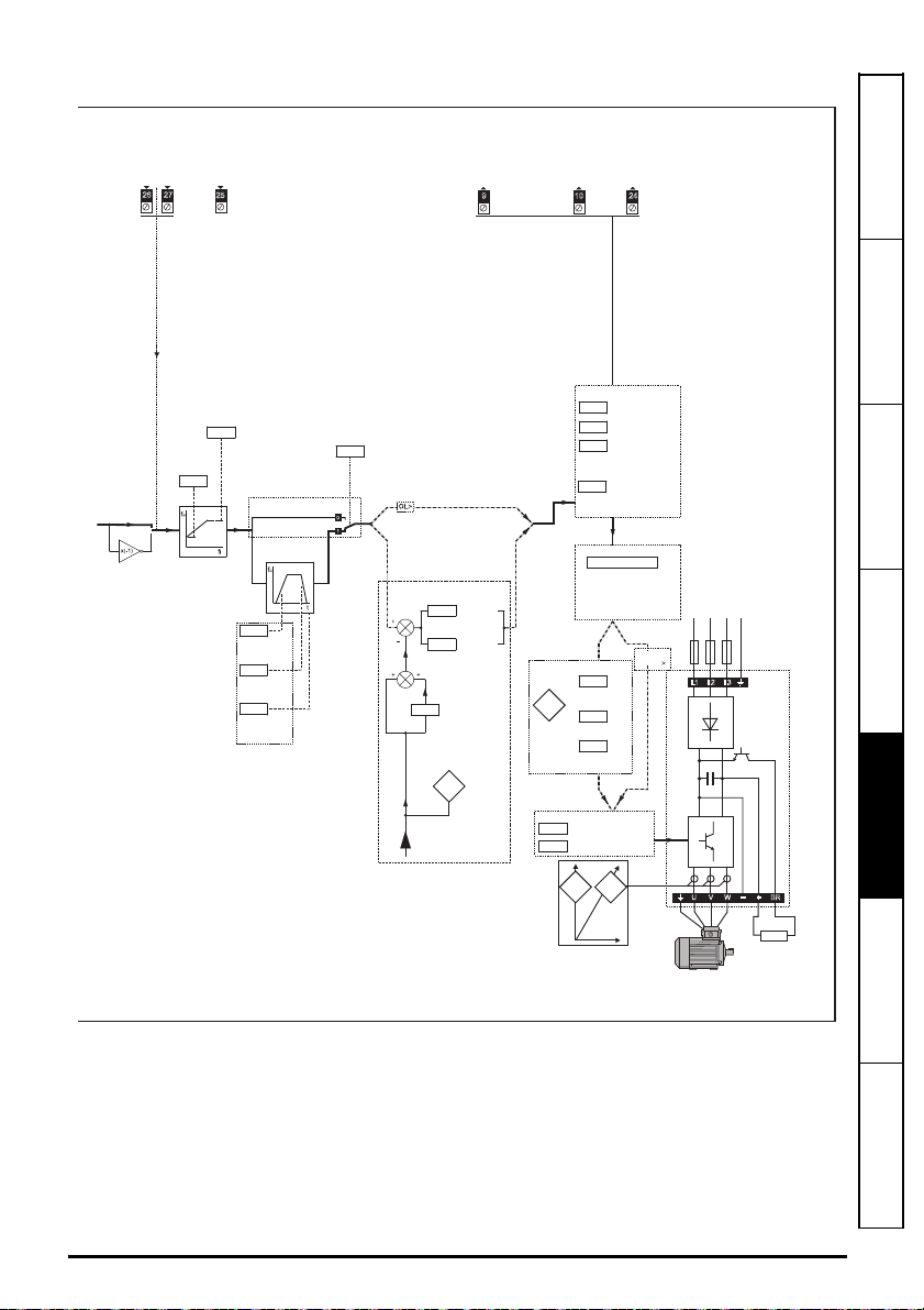
Figure 5-1 Menu 0 logic diagram
28 Unidrive M600 Control Getting Started Guide
Issue Number: 2
Safety information Introduction Control connections Getting started
TORQUE
Motor
control
Speed
Controller
Proportional
Gain KP1
OL> Catch A
Spinning Motor
RFC-A
> Motor Parameter
Adaptive Control
Speed
Feedback
00.033
00.006
00.007
00.008
00.009
RFC-A,
RFC-S>
Speed-loop
PID
gains
9 10 24
TA ZERO SPEED
Current
Limit
Number Of Motor Poles
Rated Power Factor
RatedVoltage
Rated Speed
Rated Current
Rated Frequency
00.042 ~ 00.047
Motor
parameters
Power stage
00.007
00.008
00.009
OL>
Motor-voltage control
Estimated
Motor rpm
_
+
L1 L2 L3
_
+
U V W
Resistor
optional
Drive
RUN
FORWARD
RUN
REVERSE
RESET
Maximum
Reference
Clamp
00.001
00.002
26 27
25
Ramps
Acceleration
Rate 1
Deceleration
Rate 1
Ramp Mode
00.003
00.004
00.015
RFC-A, RFC-S modes only
00.016
Ramp
Enable
Analog outputs
Digital output
00.041
00.011
Maximum Switching
Frequency
Output Frequency
00.014
TorqueMode
Selector
00.017
Current Demand
Filter Time
Constant
RFC-A,
RFC-S>
RFC-A
RFC-S
Torque
Producing
Sensorless
position
estimator
Current
Current
Magnitude
Magnetising
Current
+ BR
_
RFC-A,
RFC-S
OL> FREQUENCY
RFC-A, RFC-S> SPEED
00.010
00.010
00.013
00.012
Minimum
Reference
Clamp
Speed
Controller
Integral
Gain KI1
Speed Controller
Differential
Feedback
Gain Kd1
Open Loop
Control Mode
Low Frequency
Voltage Boost
Dynamic V to F
Select
Unidrive M600 Control Getting Started Guide 29
Issue Number: 2
Basic parameters
(Menu 0)
Running the motor Further information
6 Running the motor
WARNING
CAUT ION
CAUT ION
WARNING
This chapter takes the new user through all the essential steps to running a motor for the first time, in
each of the possible operating modes.
Ensure that no damage or safety hazard could arise from the motor starting unexpectedly.
The values of the motor parameters affect the protection of the motor.
The default values in the drive should not be relied upon.
It is essential that the correct value is entered in Pr 00.046 Rated Current. This affects the
thermal protection of the motor.
If the drive is started using the keypad it will run to the speed defined by the keypad
reference (Pr 02.017). This may not be acceptable depending on the application. The user
must check in Pr 01.017 and ensure that the keypad reference has been set to 0.
If the intended maximum speed affects the safety of the machinery, additional
independent over-speed protection must be used.
6.1 Quick start connections
6.1.1 Basic requirements
This section shows the basic connections which must be made for the drive to run in the required
mode. For minimal parameter settings to run in each mode please see the relevant part of section
6.2 Quick Start / start-up on page 32.
Table 6-1 Minimum control connection requirements for each control mode
Drive control method Requirements
Drive enable
Terminal mode
Keypad mode Drive enable
Communications
Speed / Torque reference
Run forward / Run reverse
Drive enable
Communications link
Table 6-2 Minimum control connection requirements for each mode of operation
Operating mode Requirements
Open loop mode Induction motor
RFC - A sensorless (without feedback position) Induction motor with speed feedback
RFC - S sensorless (without position feedback)
Permanent magnet motor with speed and
position feedback
30 Unidrive M600 Control Getting Started Guide
Issue Number: 2
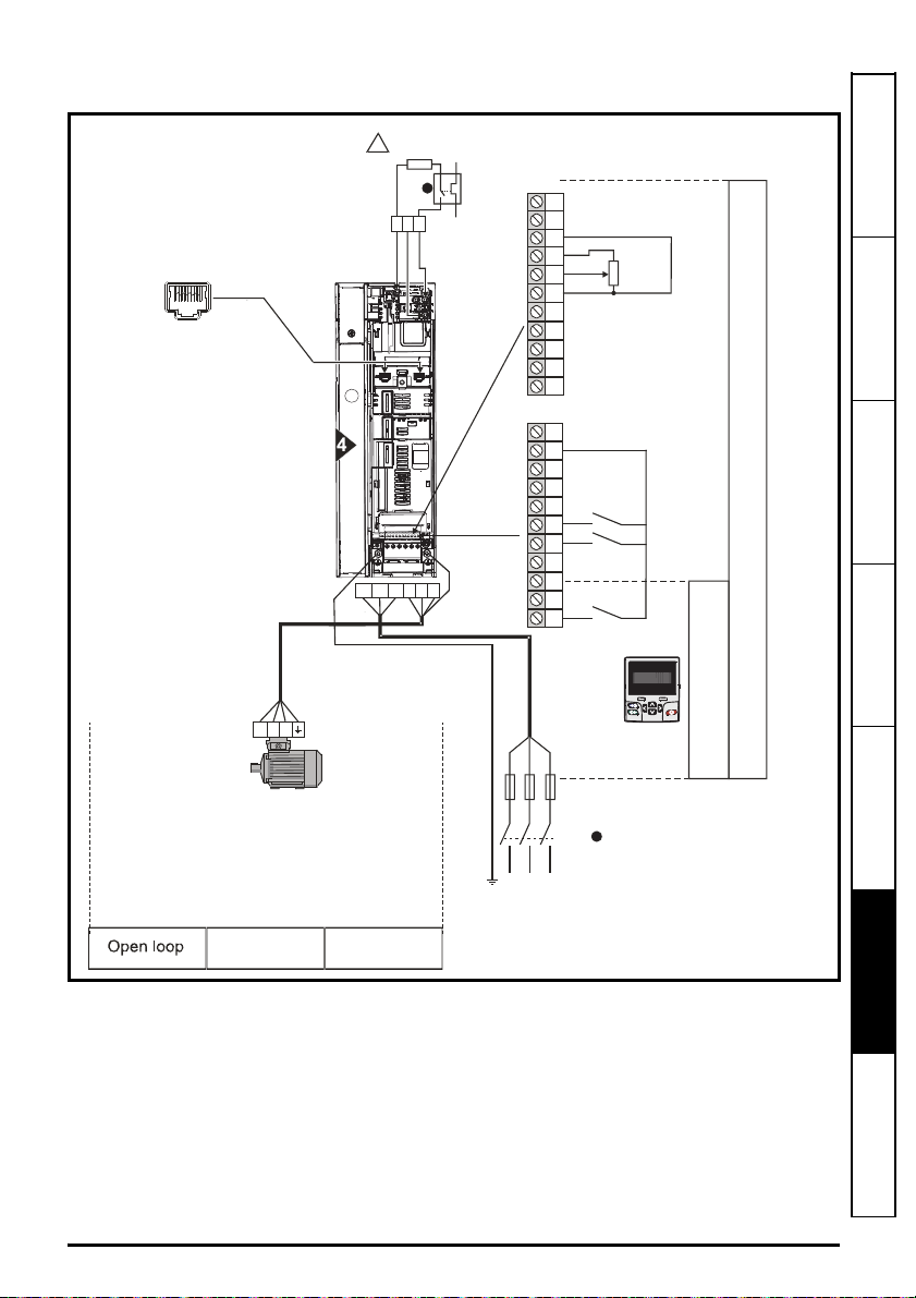
Figure 6-1 Minimum connections to get the motor running in any operating mode (size 4
Induction or permanent
magnet motor
10
11
8
9
6
7
4
5
3
Speed
reference
input
RUN FWD
RUN REV
24V
0V
+10V
Thermal overload for braking resistor
to protect against fire risk. This must be
wired to interrupt the AC supply in the
event of a fault. This is not required if the
optional internal braking resistor is used
2
1
T
e
r
m
i
n
a
l
M
o
d
e
K
e
y
p
a
d
M
o
d
e
Communications
port
Keypad
Optional item, must
be installed
for keypad mode
30
31
28
29
26
27
24
25
23
21
22
L1 L2 L3
Fuses
SAFE TORQUE OFF
(drive enable)
L1 L2 L3UV W
1
!
+
_
BR
Braking resistor
(optional)
U V W
RFC-A
Sensorless
RFC-S
Sensorless
1
illustrated)
Safety information Introduction Control connections Getting started
Basic parameters
(Menu 0)
Running the motor
Further information
Unidrive M600 Control Getting Started Guide 31
Issue Number: 2

6.2 Quick Start / start-up
Mot X XXXXXXXXX
No XXXXXXXXXX kg
IP55 I.cl F C 40 s S1
°
VHzmin-1kW cosφA
230
400
50 1445 2.20 0.80 8.50
4.90
CN = 14.5Nm
240
415
50 1445 2.20 0.76 8.50
4.90
CN = 14.4Nm
CTP- VEN 1PHASE 1=0,46 A P=110W R.F 32MN
I.E.C 34 1(87)
0.02
t
100Hz
0.03
t
0.04
6.2.1 Open loop
Action Detail
Before
power-up
Ensure:
• The drive enable signal is not given (terminal 31)
• Run signal is not given
• Motor is connected
Power-up the
drive
Enter motor
nameplate
details
Set maximum
frequency
Set
acceleration /
deceleration
rates
Motor
thermistor
set-up
Verify that Open Loop mode is displayed as the drive powers
up. If the mode is incorrect see
operating mode
on page 17 .
section 4.7 Changing the
Ensure that the drive displays ‘Inhibit’
Enter:
• Motor rated frequency in Pr 00.047 (Hz)
• Motor rated current in Pr 00.046 (A)
• Motor rated speed in Pr 00.045 (rpm)
• Motor rated voltage in Pr 00.044 (V) - check if or
connection
Enter:
• Maximum frequency in Pr 00.002 (Hz)
Enter:
• Acceleration rate in Pr 00.003 (s/100 Hz)
• Deceleration rate in Pr 00.004 (s/100 Hz) (If braking resistor
installed, set Pr 00.015 = Fast. Also ensure Pr 10.030 and
Pr 10.031 and Pr 10.061 are set correctly, otherwise
premature ‘Brake R Too Hot’ trips may be seen).
The motor thermistor can be selected in Pr 07.015. Refer to
Pr 07.015 for further information.
32 Unidrive M600 Control Getting Started Guide
Issue Number: 2

Action Detail
A rotating autotune will cause the motor to
accelerate up to
2
/3 base speed in the direction
selected regardless of the reference provided.
Once complete the motor will coast to a stop. The
enable signal must be removed before the drive
can be made to run at the required reference.
The drive can be stopped at any time by removing
the run signal or removing the drive enable.
WARNING
cos
∅
σ
L
S
R
S
The drive is able to perform either a stationary or a rotating
autotune. The motor must be at a standstill before an autotune
is enabled. A rotating autotune should be used whenever
possible so the measured value of power factor of the motor is
used by the drive.
• A stationary autotune can be used when the motor is
loaded and it is not possible to uncouple the load from the
motor shaft. A stationary autotune measures stator
resistance and transient inductance of the motor and values
Autotune
relating to deadtime compensation from the drive. These
are required for good performance in vector control modes.
A stationary autotune does not measure the power factor of
the motor so the value on the motor nameplate must be
entered into Pr 00.043.
• A rotating autotune should only be used if the motor is
uncoupled. A rotating autotune first performs a stationary
autotune before rotating the motor at
direction selected. The rotating autotune measures the
power factor of the motor.
To perform an autotune:
•Set Pr 00.040 = 1 for a stationary autotune or set Pr 00.040
= 2 for a rotating autotune
• Close the Drive Enable signal (terminal 31). The drive will
display ’Ready’.
• Close the run signal (terminal 26 or 27). The upper row of
the display will flash ’Auto Tune’ while the drive is
performing the autotune.
• Wait for the drive to display ’Ready’ or ‘Inhibit’ and for the
motor to come to a standstill.
• Remove the drive enable and run signal from the drive.
Save
parameters
Select 'Save Parameters' in Pr mm.000 (alternatively enter a
value of 1000 in Pr mm.000) and press the red reset
button or toggle the reset digital input.
2
/3 base speed in the
Safety information Introduction Control connections Getting started
Basic parameters
(Menu 0)
Running the motor
Run Drive is now ready to run
Unidrive M600 Control Getting Started Guide 33
Issue Number: 2
Further information

6.2.2 RFC-A mode (Sensorless)
Mot X XXXXXXXXX
No XXXXXXXXXX kg
IP55 I.cl F C 40 s S1
°
VHzmin-1kW cosφA
230
400
50 1445 2.20 0.80 8.50
4.90
CN = 14.5Nm
240
415
50 14452.20 0.76 8.50
4.90
CN = 14.4Nm
CTP- VEN 1PHASE 1=0,46A P=110W R.F 32MN
I.E.C 34 1(87)
0.02
1000rpm
0.03
t
0.04
Induction motor with sensorless control
Action Detail
Ensure:
Before power-up
Power-up the
drive
Enter motor
nameplate details
Set maximum
speed
Set acceleration /
deceleration
rates
• The drive enable signal is not given (terminal 31)
• Run signal is not given
• Motor is connected
Verify that RFC-A mode is displayed as the drive powers
up. If the mode is incorrect see section 4.7
operating mode
defaults (see
on page 17, otherwise restore parameter
section 4.9 Restoring parameter defaults on
page 18.
Ensure that the drive displays ‘Inhibit’
Enter:
• Motor rated frequency in Pr 00.047 (Hz)
• Motor rated current in Pr 00.046 (A)
• Motor rated speed in Pr 00.045 (rpm)
• Motor rated voltage in Pr 00.044 (V) - check if or
connection
Enter:
• Maximum speed in Pr 00.002 (rpm)
Enter:
• Acceleration rate in Pr 00.003 (s/1000rpm)
• Deceleration rate in Pr 00.004 (s/1000rpm) (If braking
resistor installed, set Pr 00.015 = FAST. Also ensure
Pr 10.030, Pr 10.031 and Pr 10.061 are set correctly,
otherwise premature ‘Brake R Too Hot’ trips may be
seen).
Changing the
34 Unidrive M600 Control Getting Started Guide
Issue Number: 2

Action Detail
NOTE
A rotating autotune will cause the motor to
accelerate up to
2
/3 base speed in the direction
selected regardless of the reference provided.
Once complete the motor will coast to a stop.
The enable signal must be removed before the
drive can be made to run at the required
reference.The drive can be stopped at any time
by removing the run signal or removing the drive
enable.
WARNING
cos
∅
σ
L
S
T
Nm
N rpm
saturation
breakpoints
R
S
L
S
The drive is able to perform either a stationary or a rotating
autotune. The motor must be at a standstill before an
autotune is enabled. A stationary autotune will give
moderate performance whereas a rotating autotune will
give improved performance as it measures the actual
values of the motor parameters required by the drive.
It is highly recommended that a rotating
autotune is performed (Pr 00.040 set to 2).
• A stationary autotune can be used when the motor is
loaded and it is not possible to uncouple the load from
the motor shaft. The stationary autotune measures the
stator resistance and transient inductance of the motor
Autotune
and values relating to deadtime compensation from the
drive. Measured values are used to calculate the
current loop gains, and at the end of the test the values
in Pr 00.038 and Pr 00.039 are updated. A stationary
autotune does not measure the power factor of the
motor so the value on the motor nameplate must be
entered into Pr 00.043.
• A rotating autotune should only be used if the motor is
uncoupled. A rotating autotune first performs a
stationary autotune before rotating the motor at 2/3
base speed in the direction selected. The rotating
autotune measures the stator inductance of the motor
and calculates the power factor.
To perform an autotune:
•Set Pr 00.040 = 1 for a stationary autotune or set
Pr 00.040 = 2 for a rotating autotune
• Close the drive enable signal (terminal 31). The drive
will display ’Ready’ or ‘Inhibit’.
• Close the run signal (terminal 26 or 27). The lower
display will flash ’Autotune’ while the drive is performing
the autotune.
• Wait for the drive to display ’Ready’ or ‘Inhibit’ and for
the motor to come to a standstill.
• Remove the drive enable and run signal from the drive.
Save parameters
Select 'Save Parameters' in Pr
value of 1000 in Pr
mm.000
mm.000
) and press red reset
button or toggle the reset digital input.
Run Drive is now ready to run
Safety information Introduction Control connections Getting started
Basic parameters
(Menu 0)
Running the motor
(alternatively enter a
Further information
Unidrive M600 Control Getting Started Guide 35
Issue Number: 2

6.2.3 RFC-A mode (with position feedback)
NOTE
Setting the encoder voltage supply too high for
the encoder could result in damage to the feedback
device.
CAUTION
Mot X XXXXXXXXX
No XXXXXXXXXX kg
IP55 I.cl F C 40 s S1
°
VHzmin-1kW cosφA
230
400
50 1445 2.20 0.80 8.50
4.90
CN = 14.5Nm
240
415
50 14452.20 0.76 8.50
4.90
CN = 14.4Nm
CTP- VEN 1PHASE 1=0,46A P=110W R.F 32MN
I.E.C 34 1(87)
0.02
t
1000rpm
0.03
t
0.04
Induction motor with position feedback using optional SI-Encoder module
Only an incremental quadrature encoder as supported by the optional SI-Encoder module
Action Detail
Before
power-up
Power-up
the drive
Enable
motor
feedback
and set
parameters
Ensure:
• The drive enable signal is not given (terminal 31).
• Run signal is not given
• Motor and feedback device are connected
Verify that RFC-A mode is displayed as the drive powers up. If the
mode is incorrect see
section 4.7 Changing the operating mode on
page 17, otherwise restore parameter defaults (see section
4.9
Restoring parameter defaults on page 18.
Ensure that the drive displays ‘Inhibit’
Incremental encoder basic set-up
Set Pr 03.024 = Feedback (0)
Enter:
• Encoder power supply in Pr. mm.036 = 5 V (0), 8 V (1) or 15 V
(2). *
If output voltage from the encoder is >5 V, then the termination
resistors must be disabled Pr mm.039 to 0. *
• Drive encoder Lines Per Revolution (LPR) in Pr mm.034 (set
according to encoder) *
• Drive encoder termination resistor setting in Pr mm.039: *
0 = A-A\, B-B\ termination resistors disabled
1 = A-A\, B-B\, termination resistors enabled
* mm is dependant on the slot into which the SI-Encoder module is
installed (15 =Slot 1, 16 = Slot 2,
17 = Slot 3).
Enter motor
nameplate
details
• Motor rated frequency in Pr 00.047 (Hz)
• Motor rated current in Pr 00.046 (A)
• Motor rated speed in Pr 00.045 (rpm)
• Motor rated voltage in Pr 00.044 (V) - check if or
connection
Set
maximum
Enter: Maximum speed in Pr 00.002 (rpm)
speed
Set
acceleration
/
deceleration
rates
Motor
thermistor
set-up
36 Unidrive M600 Control Getting Started Guide
Enter:
• Acceleration rate in Pr 00.003 (s/1000 rpm)
• Deceleration rate in Pr
installed, set Pr
Pr
10.061
are set correctly, otherwise premature ‘Brake R Too Hot’
00.004
00.015
= Fast. Also ensure Pr
(s/1000 rpm) (If braking resistor
trips may be seen).
The motor thermistor can be selected in Pr 07.015. Refer to
Pr 07.015 for further information.
10.030
, Pr
10.031
and
Issue Number: 2

Action Detail
A rotating autotune will cause the motor to accelerate up
to
2
/3 base speed in the direction selected regardless of
the reference provided. Once complete the motor will
coast to a stop. The enable signal must be removed
before the drive can be made to run at the required
reference.
The drive can be stopped at any time by removing the run
signal or removing the drive enable.
WARNING
cos
∅
σ
L
S
T
Nm
N rpm
saturation
breakpoints
R
S
L
S
The drive is able to perform either a stationary or a rotating autotune.
The motor must be at a standstill before an autotune is enabled. A
stationary autotune will give moderate performance whereas a
rotating autotune will give improved performance as it measures the
actual values of the motor parameters required by the drive.
• A stationary autotune can be used when the motor is loaded and
it is not possible to uncouple the load from the motor shaft. The
stationary autotune measures the stator resistance and transient
inductance of the motor and values relating to deadtime
compensation from the drive. Measured values are used to
Autotune
calculate the current loop gains, and at the end of the test the
values in Pr 00.038 and Pr 00.039 are updated. A stationary
autotune does not measure the power factor of the motor so the
value on the motor nameplate must be entered into Pr 00.043.
• A rotating autotune should only be used if the motor is
uncoupled. A rotating autotune first performs a stationary
autotune before rotating the motor at
direction selected. The rotating autotune measures the stator
inductance of the motor and calculates the power factor.
To perform an autotune:
•Set Pr 00.040 = 1 for a stationary autotune or set Pr 00.040 = 2
for a rotating autotune
• Close the drive enable signal (terminal 31). The drive will display
’Ready’.
• Close the run signal (terminal 26 or 27). The upper row of the
display will flash ‘Auto Tune’ while the drive is performing the
autotune.
• Wait for the drive to display ’Ready’ or ‘Inhibit’ and for the motor
to come to a standstill
• Remove the drive enable and run signal from the drive.
Save
parameters
Select 'Save Parameters' in Pr
1000 in Pr
mm.000
) and press red reset button or toggle the
reset digital input.
mm.000
(alternatively enter a value of
Run Drive is now ready to run
2
/3 base speed in the
Safety information Introduction Control connections Getting started
Basic parameters
(Menu 0)
Running the motor
Unidrive M600 Control Getting Started Guide 37
Issue Number: 2
Further information

6.2.4 RFC-S mode (Sensorless)
Model No: 95UXXXXXXXXXXXX
Volts: 380/480
Cont: 7.7Nm:4.81 Arms
Stall: 9.5Nm:5.91Arms
Speed: 3000rpm Poles:6
Kt: 1.6Nm/Arms
Ins Class: H
Brake: 12Nm
24V
0.67A
Serial No: XXXXXXXXXXX
Control Techniques
Dynamics Ltd
ANDOVER, HANTS.
ENGLAND. SP10 5AB
0.02
t
1000rpm
0.03
t
0.04
Ld
No-load Lq
R
S
Ef
Permanent magnet motor without position feedback
Action Detail
Before powerup
Power-up the
drive
Enter motor
nameplate
details
Ensure:
• The drive enable signal is not given (terminal 31).
• Run signal is not given
• Motor is connected
Verify that RFC-S mode is displayed as the drive powers up. If the mode
is incorrect see section 4.7
Changing the operating mode on
page 17, otherwise restore parameter defaults (see section
Restoring parameter defaults on page 18).
4.9
Ensure that the drive displays ‘inhibit’
Enter:
• Motor rated current in Pr 00.046 (A)
Ensure that this equal to or less than the Heavy Duty rating of the
drive otherwise ‘Motor Too Hot’ trips may occur during the autotune.
• Number of poles in Pr 00.042
• Motor rated voltage in Pr 00.044 (V)
Set maximum
speed
Enter:
• Maximum speed in Pr 00.002 (rpm)
Enter:
Set
acceleration /
deceleration
rates
• Acceleration rate in Pr 00.003 (s/1000 rpm)
• Deceleration rate in Pr 00.004 (s/1000 rpm) (If braking resistor
installed, set Pr 00.015 = Fast. Also ensure Pr 10.030, Pr 10.031
and Pr 10.061 are set correctly, otherwise premature ‘Brake R Too
Hot’ trips may be seen).
The drive is able to perform a stationary autotune. The motor must be at
a standstill before an autotune is enabled. A stationary autotune will give
moderate performance.
• A stationary autotune is performed to locate the flux axis of the
motor. The stationary autotune measures the stator resistance,
inductance in flux axis, inductance in torque axis with no load on the
motor and values relating to deadtime compensation from the drive.
Measured values are used to calculate the current loop gains, and
at the end of the test the values in Pr 00.038 and Pr 00.039 are
Autotune
updated.
To perform an autotune:
•Set Pr 00.040 = 1 or 2 for a stationary autotune. (Both perform the
same tests).
• Close the run signal (terminal 26 or 27).
• Close the drive enable signal (terminal 31). The upper row of the
display will flash 'Auto Tune' during the test.
• Wait for the drive to display 'Ready' or 'Inhibit'.
If the drive trips it cannot be reset until the drive enable signal (terminal
31) has been removed.
• Remove the drive enabled and run signal from the drive.
In sensorless mode, when the motor speed is below Pr
special low speed algorithm must be used to control the motor. There are
Check
Saliency
Save
parameters
two modes available, with the mode chosen based on the saliency of the
motor. The ratio No-load Lq (Pr
measure of the saliency. If this value is > 1.1, then Non-salient mode
must be used (this is the default), otherwise Injection mode may be used.
00.054
Set Pr
for the selected mode: Injection (0) or Non-salient (1).
Select 'Save Parameters' in Pr
mm.000
in Pr
) and press red reset button or toggle the reset
digital input.
Run Drive is now ready to run
00.056
) / Ld (Pr
05.024
mm.000
(alternatively enter a value of 1000
00.045
/ 10, a
) provides a
38 Unidrive M600 Control Getting Started Guide
Issue Number: 2
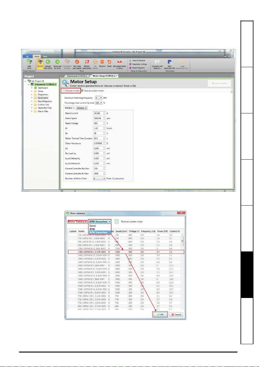
6.2.5 Use of the motor database for a Leroy Somer LSRPM motor for use in
RFC-S Sensorless mode.
Select 'Motor Setup' from the 'Dashboard'.
On the 'Motor Setup' screen, select 'Choose a motor'.
Select the required motor database:
Select the required motor from the list and click 'OK'.
Safety information Introduction Control connections Getting started
Basic parameters
(Menu 0)
Unidrive M600 Control Getting Started Guide 39
Issue Number: 2
Running the motor
Further information

The data for the selected motor is displayed on the 'Motor Setup' screen. Click 'Send to drive' to set the
associated parameters.
It is possible to set motor parameters for motor 2, by selecting the 'Motor 2' tab and following the same procedure.
40 Unidrive M600 Control Getting Started Guide
Issue Number: 2

7 Further information
7.1 Diagnostics
For further information on diagnostics including trips and alarms, refer to the Control User
Guide.
Safety information Introduction Control connections Getting started
Unidrive M600 Control Getting Started Guide 41
Issue Number: 2
Basic parameters
(Menu 0)
Running the motor
Further information

1
11
Polarised signal
connectors
21 31
41
42
Analog frequency/speed
reference 1
Single-ended
signal
Differential signal
Analog input 2
Analog input 1
1
2
5
6
3
5
6
3
21
22
23
24
25
26
27
28
29
30
31
41
42
At zero speed
Reset
Run forward
Run reverse
Analog input 1/
input 2 select
Jog forward select
Drive ok
Speed / frequency
Analog
frequency/speed
reference 2
4
7
11
9
10
8
Torque (active
current)
Analog input 3
0V
+24V input
0V
Non-inverting input
Inverting input
0V
Non-inverting input
Inverting input
+10V output
Analog input 2
Analog input 3
Analog output 1
Analog output 2
0V
0V
+24V output
(user selectable)
0V
Digital I/O 1
Digital I/O 2
Digital I/O 3
Digital input 4
Digital input 5
Digital input 6
0V
Drive enable (SAFE
TORQUE OFF function)
Relay (Overvoltage
category II)
0478-0240-02
 Loading...