

Control User Guide
Unidrive M600
Part Number: 0478-0337-02
Issue: 2

Original Instructions
For the purposes of compliance with the EU Machinery Directive 2006/42/EC, the English version of this manual is the Original Instructions. Manuals
in other languages are Translations of the Original Instructions.
Documentation
Manuals are available to download from the following locations: http://www.drive-setup.com/ctdownloads
The information contained in this manual is believed to be correct at the time of printing and does not form part of any contract. The manufacturer
reserves the right to change the specification of the product and its performance, and the contents of the manual, without notice.
Warranty and Liability
In no event and under no circumstances shall the manufacturer be liable for damages and failures due to misuse, abuse, improper installation, or
abnormal conditions of temperature, dust, or corrosion, or failures due to operation outside the published ratings. The manufacturer is not liable for
consequential and incidental damages. Contact the supplier of the dive for full details of the warranty terms.
Environmental policy
Control Techniques Ltd operates an Environmental Management System (EMS) that conforms to the International Standard ISO 14001.
Further information on our Environmental Policy can be found at: http://www.drive-setup.com/environment
Restriction of Hazardous Substances (RoHS)
The products covered by this manual comply with European and International regulations on the Restriction of Hazardous Substances including EU
directive 2011/65/EU and the Chinese Administrative Measures for Restriction of Hazardous Substances in Electrical and Electronic Products.
Disposal and Recycling (WEEE)
When electronic products reach the end of their useful life, they must not be disposed of along with domestic waste but should be recycled
by a specialist recycler of electronic equipment. Control Techniques products are designed to be easily dismantled into their major
component parts for efficient recycling. The majority of materials used in the product are suitable for recycling.
Product packaging is of good quality and can be re-used. Large products are packed in wooden crates. Smaller products are packaged
in strong cardboard cartons which have a high recycled fibre content. Cartons can be re-used and recycled. Polythene, used in protective
film and bags for wrapping the product, can be recycled. When preparing to recycle or dispose of any product or packaging, please
observe local legislation and best practice.
REACH legislation
EC Regulation 1907/2006 on the Registration, Evaluation, Authorisation and restriction of Chemicals (REACH) requires the supplier of an article to
inform the recipient if it contains more than a specified proportion of any substance which is considered by the European Chemicals Agency (ECHA)
to be a Substance of Very High Concern (SVHC) and is therefore listed by them as a candidate for compulsory authorisation.
Further information on our compliance with REACH can be found at: http://www.drive-setup.com/reach
Registered Office
Nidec Control Techniques Ltd
The Gro
Newtown
Powys
SY16 3BE
UK
Registered in England and Wales. Company Reg. No. 01236886.
Copyright
The contents of this publication are believed to be correct at the time of printing. In the interests of a commitment to a policy of continuous development
and improvement, the manufacturer reserves the right to change the specification of the product or its performance, or the contents of the guide, without
notice.
All rights reserved. No parts of this guide may be reproduced or transmitted in any form or by any means, electrical or mechanical including
photocopying, recording or by an information storage or retrieval system, without permission in writing from the publisher.
Copyright © December 2017 Nidec Control Techniques Ltd
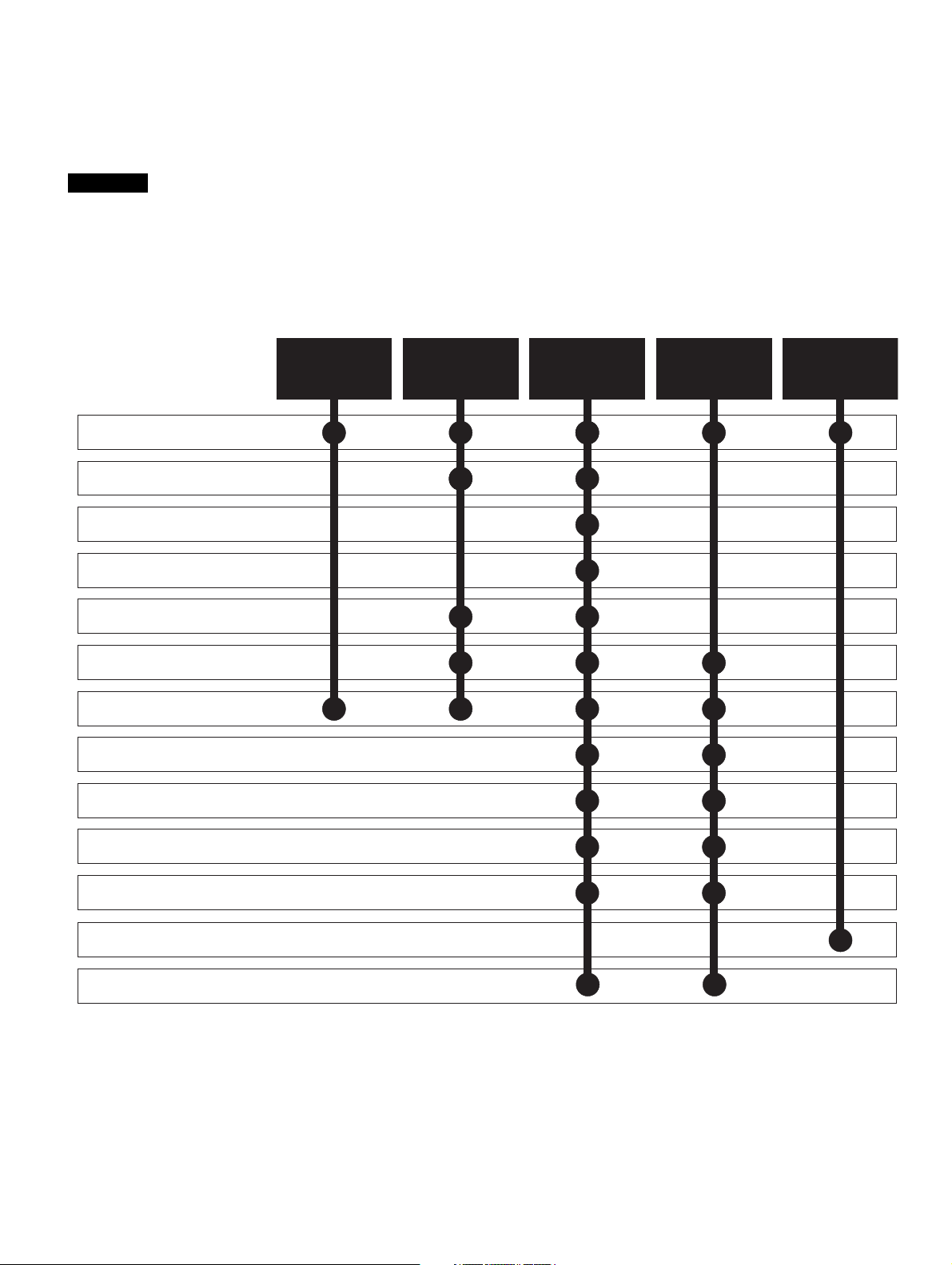
How to use this guide
NOTE
Quick Start /
bench testing
Quick Start /
bench
testing
Familiarisation
System designSystem design
Programming
and
commissioning
Programming
and
commissioning
Troubleshooting
1 Safety information
2 Product information
3 Mechanical installation
4 Electrical installation
5 Getting started
6 Basic parameters
7 Running the motor
8 Optimization
9 NV media card operation
11 Advanced parameters
12 Diagnostics
13 UL listing information
10 Onboard PLC
This guide is intended to be used in conjunction with the appropriate Power Installation Guide. The Power Installation
Guide gives information necessary to physically install the drive. This guide gives information on drive configuration,
operation and optimization.
There are specific safety warnings throughout this guide, located in the relevant sections. In addition, Chapter 1 Safety
information contains general safety information. It is essential that the warnings are observed and the information
considered when working with or designing a system using the drive.
This map of the user guide helps to find the right sections for the task you wish to complete, but for specific information,
refer to :

Contents
1 Safety information .................................9
1.1 Warnings, Cautions and Notes .............................9
1.2 Important safety information. Hazards.
Competence of designers and installers ...............9
1.3 Responsibility ........................................................9
1.4 Compliance with regulations .................................9
1.5 Electrical hazards ..................................................9
1.6 Stored electrical charge ........................................9
1.7 Mechanical hazards ..............................................9
1.8 Access to equipment .............................................9
1.9 Environmental limits ..............................................9
1.10 Hazardous environments ......................................9
1.11 Motor ...................................................................10
1.12 Mechanical brake control ....................................10
1.13 Adjusting parameters ..........................................10
1.14 Electromagnetic compatibility (EMC) ..................10
2 Product information ............................11
2.1 Introduction .........................................................11
2.2 Drive firmware version ........................................11
2.3 Model number .....................................................11
2.4 Ratings ................................................................12
2.5 Operating modes .................................................13
2.6 Nameplate description ........................................14
2.7 Options ................................................................15
2.8 Drive features ......................................................17
3 Mechanical installation .......................18
3.1 Installing / removing option modules and
keypads ...............................................................18
4 Electrical installation ...........................21
4.1 24 Vdc supply ......................................................21
4.2 Communication connections ...............................22
4.3 Control connections ............................................23
4.4 Safe Torque Off (STO) ........................................28
6 Running the motor .............................. 59
6.1 Quick start connections ...................................... 59
6.2 Changing the operating mode ............................ 59
6.3 Quick start commissioning / start-up .................. 64
6.4 Quick start commissioning / start-up using
Unidrive M Connect (V02.00.00.00 onwards) .... 72
6.5 Diagnostics ......................................................... 76
7 Optimization ........................................ 77
7.1 Motor map parameters ....................................... 77
7.2 Maximum motor rated current ............................ 89
7.3 Current limits ...................................................... 89
7.4 Motor thermal protection .................................... 89
7.5 Switching frequency ........................................... 90
7.6 High speed operation ......................................... 90
7.7 CT Modbus RTU specification ........................... 92
8 NV Media Card Operation .................. 99
8.1 Introduction ........................................................ 99
8.2 NV Media Card support ...................................... 99
8.3 Transferring data .............................................. 100
8.4 Data block header information ......................... 101
8.5 NV Media Card parameters ............................. 102
8.6 NV Media Card trips ......................................... 103
9 Onboard PLC ..................................... 104
9.1 Onboard PLC and Machine Control Studio ...... 104
9.2 Benefits ............................................................ 104
9.3 Features ........................................................... 104
9.4 Onboard PLC parameters ................................ 105
9.5 Onboard PLC trips ........................................... 105
5 Getting started .....................................30
5.1 Understanding the display ...................................30
5.2 Keypad operation ................................................30
5.3 Menu structure ....................................................32
5.4 Menu 0 ................................................................33
5.5 Advanced menus ................................................33
5.6 Changing the operating mode .............................35
5.7 Saving parameters ..............................................35
5.8 Restoring parameter defaults ..............................36
5.9 Parameter access level and security ..................36
5.10 Displaying parameters with non-default
values only ..........................................................37
5.11 Displaying destination parameters only ..............37
5.12 Communications .................................................37
6 Basic parameters .................................38
6.1 Menu 0: Basic parameters ..................................39
6.2 Parameter descriptions .......................................44
6.3 Full descriptions ..................................................46
4 Unidrive M600 Control User Guide
Issue Number: 2

10 Advanced parameters .......................106
10.1 Parameter ranges and Variable minimum/
maximums: ........................................................109
10.2 Menu 1: Frequency / speed reference ..............120
10.3 Menu 2: Ramps .................................................124
10.4 Menu 3: Speed feedback and speed control ....127
10.5 Menu 4: Torque and current control ..................131
10.6 Menu 5: Motor control .......................................135
10.7 Menu 6: Sequencer and clock ..........................140
10.8 Menu 7: Analog I/O ...........................................144
10.9 Menu 8: Digital I/O ............................................148
10.10 Menu 9: Programmable logic, motorized
pot, binary sum and timers ................................152
10.11 Menu 10: Status and trips .................................158
10.12 Menu 11: General drive set-up .........................160
10.13 Menu 12: Threshold detectors, variable
selectors and brake control function .................162
10.14 Menu 13: Standard motion controller ................170
10.15 Menu 14: User PID controller ............................174
10.16 Menus 15, 16 and 17: Option module set-up ....177
10.17 Menu 18: Application menu 1 ...........................178
10.18 Menu 19: Application menu 2 ...........................178
10.19 Menu 20: Application menu 3 ...........................178
10.20 Menu 21: Second motor parameters ................179
10.21 Menu 22: Additional Menu 0 set-up ..................181
11 Diagnostics ........................................183
11.1 Status modes (Keypad and LED status) ...........183
11.2 Trip indications ..................................................183
11.3 Identifying a trip / trip source .............................184
11.4 Trips, Sub-trip numbers ....................................185
11.5 Internal / Hardware trips ....................................211
11.6 Alarm indications ...............................................211
11.7 Status indications ..............................................211
11.8 Programming error indications ..........................212
11.9 Displaying the trip history ..................................212
11.10 Behavior of the drive when tripped ...................212
12 UL Information ...................................213
12.1 UL file reference ................................................213
12.2 Option modules, kits and accessories ..............213
12.3 Enclosure ratings ..............................................213
12.4 Mounting ...........................................................213
12.5 Environment ......................................................213
12.6 Electrical Installation .........................................213
12.7 Motor overload protection and thermal
memory retention ..............................................214
12.8 Electrical supply ................................................214
12.9 External Class 2 supply ....................................214
12.10 Requirement for Transient Surge Suppression .214
12.11 Group Installation and Modular Drive Systems .214
12.12 cUL requirements for 575 V frame size 7 and 8 214
Unidrive M600 Control User Guide 5
Issue Number: 2
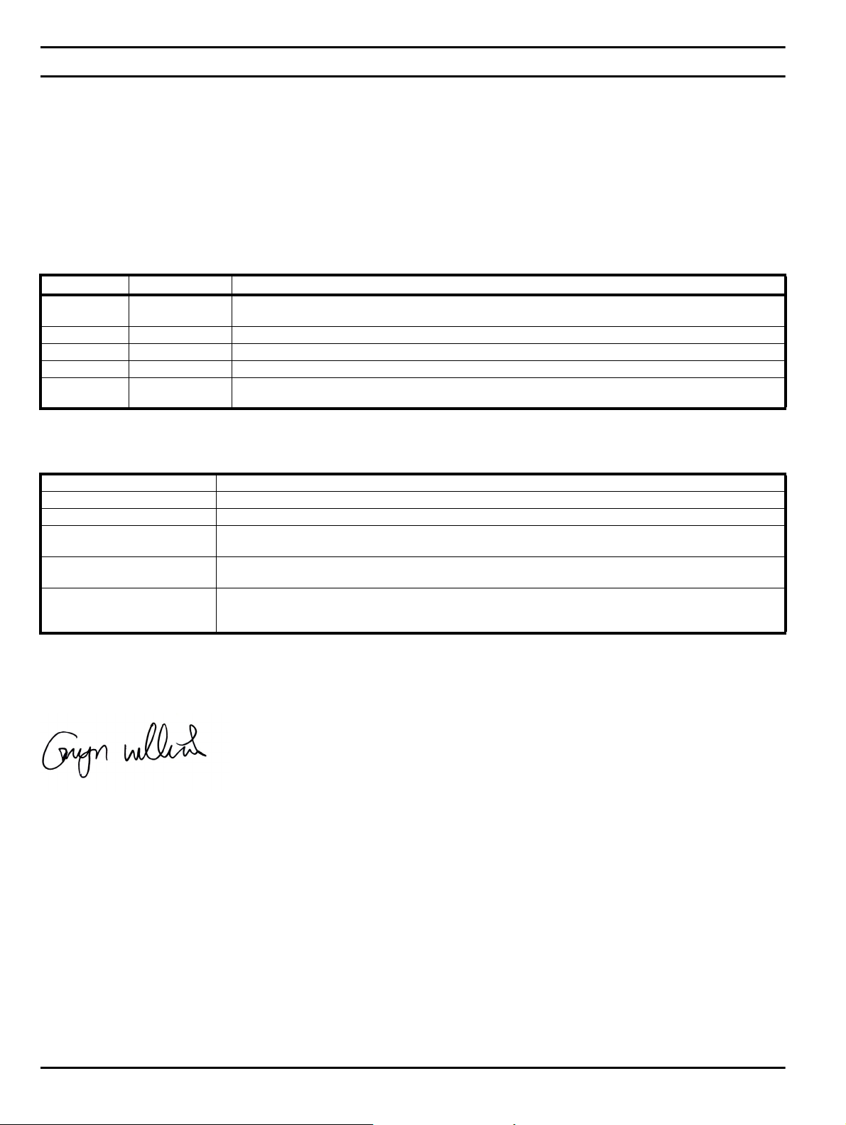
EU Declaration of Conformity
Nidec Control Techniques Ltd
The Gro
Newtown
Powys
UK
SY16 3BE
This declaration is issued under the sole responsibility of the manufacturer. The object of the declaration is in conformity with the relevant European
Union harmonization legislation. The declaration applies to the variable speed drive products shown below:
Model number Interpretation Nomenclature aaaa - bbc ddddde
aaaa Basic series
bb Frame size 01, 02, 03, 04, 05, 06, 07, 08, 09, 10, 11
c Voltage rating 1 = 100 V, 2 = 200 V, 4 = 400 V, 5 = 575 V, 6 = 690 V
ddddd Current rating Example 01000 = 100 A
e Drive format
The model number may be followed by additional characters that do not affect the ratings.
The variable speed drive products listed above have been designed and manufactured in accordance with the following European harmonized
standards:
M100, M101, M200, M201, M300, M400, M600, M700, M701, M702, M708, M709, M751, M753, M754,
F300, H300, E200, E300, HS30, HS70, HS71, HS72, M000, RECT
A = 6P Rectifier + Inverter (internal choke), D = Inverter, E = 6P Rectifier + Inverter (external choke),
T = 12P Rectifier + Inverter (external choke)
EN 61800-5-1:2007 Adjustable speed electrical power drive systems - Part 5-1: Safety requirements - Electrical, thermal and energy
EN 61800-3: 2004+A1:2012 Adjustable speed electrical power drive systems - Part 3: EMC requirements and specific test methods
EN 61000-6-2:2005 Electromagnetic compatibility (EMC) - Part 6-2: Generic standards - Immunity for industrial environments
EN 61000-6-4: 2007+ A1:2011
EN 61000-3-2:2014
EN 61000-3-3:2013
EN 61000-3-2:2014 Applicable where input current < 16 A. No limits apply for professional equipment where input power ≥1 kW.
These products comply with the Restriction of Hazardous Substances Directive (2011/65/EU), the Low Voltage Directive (2014/35/EU) and the
Electromagnetic Compatibility Directive (2014/30/EU).
G Williams
Vice President, Technology
Date: 6th September 2017
These electronic drive products are intended to be used with appropriate motors, controllers, electrical protection components and other
equipment to form complete end products or systems. Compliance with safety and EMC regulations depends upon installing and
configuring drives correctly, including using the specified input filters.
The drives must be installed only by professional installers who are familiar with requirements for safety and EMC. Refer to the Product
Documentation. An EMC data sheet is available giving detailed information. The assembler is responsible for ensuring that the end product
or system complies with all the relevant laws in the country where it is to be used.
Electromagnetic compatibility (EMC) - Part 6-4: Generic standards - Emission standard for industrial
environments
Electromagnetic compatibility (EMC) - Part 3-2: Limits for harmonic current emissions (equipment input current
≤16 A per phase)
Electromagnetic compatibility (EMC) - Part 3-3: Limitation of voltage changes, voltage fluctuations and flicker in
public, low voltage supply systems, for equipment with rated current ≤16 A per phase and not subject to
conditional connection
6 Unidrive M600 Control User Guide
Issue Number: 2

EU Declaration of Conformity (including 2006 Machinery Directive)
Nidec Control Techniques Ltd
The Gro
Newtown
Powys
UK
SY16 3BE
This declaration is issued under the sole responsibility of the manufacturer. The object of the declaration is in conformity with the relevant Union
harmonization legislation. The declaration applies to the variable speed drive products shown below:
Model No. Interpretation Nomenclature aaaa - bbc ddddde
aaaa Basic series
bb Frame size 01, 02, 03, 04, 05, 06, 07, 08, 09, 10, 11
c Voltage rating 1 = 100 V, 2 = 200 V, 4 = 400 V, 5 = 575 V, 6 = 690 V
ddddd Current rating Example 01000 = 100 A
e Drive format
The model number may be followed by additional characters that do not affect the ratings.
This declaration relates to these products when used as a safety component of a machine. Only the Safe Torque Off function may be used
for a safety function of a machine. None of the other functions of the drive may be used to carry out a safety function.
These products fulfil all the relevant provisions of the Machinery Directive 2006/42/EC and the Electromagnetic Compatibility Directive (2014/30/EU).
EC type examination has been carried out by the following notified body:
TUV Rheinland Industrie Service GmbH
Am Grauen Stein
D-51105 Köln
Germany
M600, M700, M701, M702, M708, M709, M751, M753, M754, F300, H300, E200, E300, HS70, HS71, HS72,
M000, RECT
A = 6P Rectifier + Inverter (internal choke), D = Inverter, E = 6P Rectifier + Inverter (external choke),
T = 12P Rectifier + Inverter (external choke)
The harmonized standards used are shown below:
EC type-examination certificate numbers:
01/205/5270.02/17 dated 2017-08-28
Notified body identification number: 0035
EN 61800-5-1:2016 Adjustable speed electrical power drive systems - Part 5-2: Safety requirements - Functional
EN 61800-5-1:2016 (in
extracts)
EN 61800-3: 2004+A1:2012 Adjustable speed electrical power drive systems - Part 3: EMC requirements and specific test methods
EN ISO 13849-1:2015 Safety of Machinery, Safety-related parts of control systems, General principles for design
EN 62061:2005 + AC:2010
+ A1:2013 + A2:2015
IEC 61508 Parts 1 - 7:2010 Functional safety of electrical/ electronic/programmable electronic safety-related systems
Person authorised to complete the technical file:
P Knight
Conformity Engineer
Newtown, Powys, UK
Adjustable speed electrical power drive systems - Part 5-1: Safety requirements - Electrical, thermal and energy
Safety of machinery, Functional safety of safety related electrical, electronic and programmable electronic control
systems
Unidrive M600 Control User Guide 7
Issue Number: 2

DoC authorised by:
G. Williams
Vice President, Technology
Date: 6th September 2017
Place: Newtown, Powys, UK
IMPORTANT NOTICE
These electronic drive products are intended to be used with appropriate motors, controllers, electrical protection components and other
equipment to form complete end products or systems. It is the responsibility of the installer to ensure that the design of the complete
machine, including its safety-related control system, is carried out in accordance with the requirements of the Machinery Directive and any
other relevant legislation. The use of a safety-related drive in itself does not ensure the safety of the machine. Compliance with safety and
EMC regulations depends upon installing and configuring drives correctly, including using the specified input filters. The drive must be
installed only by professional installers who are familiar with requirements for safety and EMC. The assembler is responsible for ensuring
that the end product or system complies with all relevant laws in the country where it is to be used. For more information regarding Safe
Torque Off, refer to the Product Documentation.
8 Unidrive M600 Control User Guide
Issue Number: 2

Safety
WARNING
CAUTION
NOTE
information
Product
information
Mechanical
installation
Electrical
installation
Getting
started
Basic
parameters
Running the
motor
Optimization
NV Media Card
Operation
Onboard
PLC
Advanced
parameters
Diagnostics
UL
Information
1 Safety information
1.1 Warnings, Cautions and Notes
A Warning contains information which is essential for
avoiding a safety hazard.
A Caution contains information which is necessary for
avoiding a risk of damage to the product or other equipment.
A Note contains information which helps to ensure correct operation of
the product.
1.2 Important safety information. Hazards.
This guide applies to products which control electric motors either
directly (drives) or indirectly (controllers, option modules and other
auxiliary equipment and accessories). In all cases the hazards
associated with powerful electrical drives are present, and all safety
information relating to drives and associated equipment must be
observed.
Specific warnings are given at the relevant places in this guide.
Drives and controllers are intended as components for professional
incorporation into complete systems. If installed incorrectly they may
present a safety hazard. The drive uses high voltages and currents,
carries a high level of stored electrical energy, and is used to control
equipment which can cause injury. Close attention is required to the
electrical installation and the system design to avoid hazards either in
normal operation or in the event of equipment malfunction. System
design, installation, commissioning/start-up and maintenance must be
carried out by personnel who have the necessary training and
competence. They must read this safety information and this guide
carefully.
1.3 Responsibility
It is the responsibility of the installer to ensure that the equipment is
installed correctly with regard to all instructions given in this guide. They
must give due consideration to the safety of the complete system, so as
to avoid the risk of injury both in normal operation and in the event of a
fault or of reasonably foreseeable misuse.
The manufacturer accepts no liability for any consequences resulting
from inappropriate, negligent or incorrect installation of the equipment.
1.4 Compliance with regulations
The installer is responsible for complying with all relevant regulations,
such as national wiring regulations, accident prevention regulations and
electromagnetic compatibility (EMC) regulations. Particular attention
must be given to the cross-sectional areas of conductors, the selection
of fuses or other protection, and protective ground (earth) connections.
This guide contains instructions for achieving compliance with specific
EMC standards.
All machinery to be supplied within the European Union in which this
product is used must comply with the following directives:
2006/42/EC Safety of machinery.
2014/30/EU: Electromagnetic Compatibility.
Competence of designers and
installers
1.5 Electrical hazards
The voltages used in the drive can cause severe electrical shock and/or
burns, and could be lethal. Extreme care is necessary at all times when
working with or adjacent to the drive. Hazardous voltage may be present
in any of the following locations:
• AC and DC supply cables and connections
• Output cables and connections
• Many internal parts of the drive, and external option units
Unless otherwise indicated, control terminals are single insulated and
must not be touched.
The supply must be disconnected by an approved electrical isolation
device before gaining access to the electrical connections.
The STOP and Safe Torque Off functions of the drive do not isolate
dangerous voltages from the output of the drive or from any external
option unit.
The drive must be installed in accordance with the instructions given in
this guide. Failure to observe the instructions could result in a fire
hazard.
1.6 Stored electrical charge
The drive contains capacitors that remain charged to a potentially lethal
voltage after the AC supply has been disconnected. If the drive has been
energized, the AC supply must be isolated at least ten minutes before
work may continue.
1.7 Mechanical hazards
Careful consideration must be given to the functions of the drive or
controller which might result in a hazard, either through their intended
behaviour or through incorrect operation due to a fault. In any application
where a malfunction of the drive or its control system could lead to or
allow damage, loss or injury, a risk analysis must be carried out, and
where necessary, further measures taken to reduce the risk - for
example, an over-speed protection device in case of failure of the speed
control, or a fail-safe mechanical brake in case of loss of motor braking.
With the sole exception of the Safe Torque Off function, none of the
drive functions must be used to ensure safety of personnel, i.e.
they must not be used for safety-related functions.
The Safe Torque Off function may be used in a safety-related
application. The system designer is responsible for ensuring that the
complete system is safe and designed correctly according to the
relevant safety standards.
The design of safety-related control systems must only be done by
personnel with the required training and experience. The Safe Torque
Off function will only ensure the safety of a machine if it is correctly
incorporated into a complete safety system. The system must be subject
to a risk assessment to confirm that the residual risk of an unsafe event
is at an acceptable level for the application.
1.8 Access to equipment
Access must be restricted to authorized personnel only. Safety
regulations which apply at the place of use must be complied with.
1.9 Environmental limits
Instructions in this guide regarding transport, storage, installation and
use of the equipment must be complied with, including the specified
environmental limits. This includes temperature, humidity,
contamination, shock and vibration. Drives must not be subjected to
excessive physical force.
1.10 Hazardous environments
The equipment must not be installed in a hazardous environment (i.e. a
potentially explosive environment).
Unidrive M600 Control User Guide 9
Issue Number: 2

Safety
information
Product
information
Mechanical
installation
Electrical
installation
Getting
started
Basic
parameters
Running the
1.11 Motor
The safety of the motor under variable speed conditions must be
ensured.
To avoid the risk of physical injury, do not exceed the maximum specified
speed of the motor.
Low speeds may cause the motor to overheat because the cooling fan
becomes less effective, causing a fire hazard. The motor should be
installed with a protection thermistor. If necessary, an electric forced vent
fan should be used.
The values of the motor parameters set in the drive affect the protection
of the motor. The default values in the drive must not be relied upon. It is
essential that the correct value is entered in the Motor Rated Current
parameter.
1.12 Mechanical brake control
Any brake control functions are provided to allow well co-ordinated
operation of an external brake with the drive. While both hardware and
software are designed to high standards of quality and robustness, they
are not intended for use as safety functions, i.e. where a fault or failure
would result in a risk of injury. In any application where the incorrect
operation of the brake release mechanism could result in injury,
independent protection devices of proven integrity must also be
incorporated.
1.13 Adjusting parameters
Some parameters have a profound effect on the operation of the drive.
They must not be altered without careful consideration of the impact on
the controlled system. Measures must be taken to prevent unwanted
changes due to error or tampering.
motor
Optimization
NV Media Card
Operation
Onboard
PLC
Advanced
parameters
Diagnostics
UL
Information
1.14 Electromagnetic compatibility (EMC)
Installation instructions for a range of EMC environments are provided in
the relevant Power Installation Guide. If the installation is poorly
designed or other equipment does not comply with suitable standards for
EMC, the product might cause or suffer from disturbance due to
electromagnetic interaction with other equipment. It is the responsibility
of the installer to ensure that the equipment or system into which the
product is incorporated complies with the relevant EMC legislation in the
place of use.
10 Unidrive M600 Control User Guide
Issue Number: 2
Safety
Identification Label
Electrical Specifications
Derivative
Unidrive M600
Product Line
Frame Size:
Voltage Rating :
Current Rating:
Heavy Duty current rating x10
Power Format:
Reserved
0
Optional Build
Customer Code
01
A B 1 00
Customer Code:
00 = 50 Hz
01 = 60 Hz
Reserved:
Conformal Coating:
0=Standard
IP / NEMA Rating:
1=IP20 / NEMA 1
Brake Transistor:
B=Brake
Cooling:
A=Air
Documentation
1
Documentation:
0 - Supplied separately
1 - English
2 - French
3 - Italian
4 - German
5 - Spanish
2 - 200 V (200 - 240
- 400 V (380 - 480
- 575 V (500 - 575
- 690 V (500 - 690
± 10 %)
4 ±
±
±
10 %)
510 %)
610 %)
Power
Format
M600 - 03 4 00078 A
Configuration*
1
A - AC inAC out (with internal choke)
D - DC in AC out (Inverter)
C - AC in DC out (Rectifier)
E - AC in AC out (without internal choke)
Configuration:
1 - Standard
U - No Control
M - Master
F - Follower
T - AC in AC out (12P rectifier plus inverter)
N = No brake
NOTE
information
Product
information
Mechanical
installation
Electrical
installation
Getting
started
Basic
parameters
Running the
motor
Optimization
NV Media Card
Operation
Onboard
PLC
Advanced
parameters
Diagnostics
UL
Information
2 Product information
2.1 Introduction
Universal AC and servo drive
Unidrive M600 delivers maximum machine performance with sensorless induction and sensorless permanent magnet motor control, for dynamic and
efficient machine operation. An optional encoder port can be used for precise closed loop velocity applications and digital lock / frequency following.
Features
• Universal high performance drive for induction and sensorless permanent magnet motors.
• Onboard IEC 61131-3 programmable automation
• NV Media Card for parameter copying and data storage
• EIA 485 serial communications interface
• Single channel Safe Torque Off (STO) input
Optional features
• Select up to three option modules
2.2 Drive firmware version
This product is supplied with the latest firmware version. If this drive is to be connected to an existing system or machine, all drive firmware versions
should be verified to confirm the same functionality as drives of the same model already present. This may also apply to drives returned from an
Nidec Industrial Automation Service Centre or Repair Centre. If there is any doubt please contact the supplier of the product.
The firmware version of the drive can be checked by looking at Pr 00.050 {11.029}.
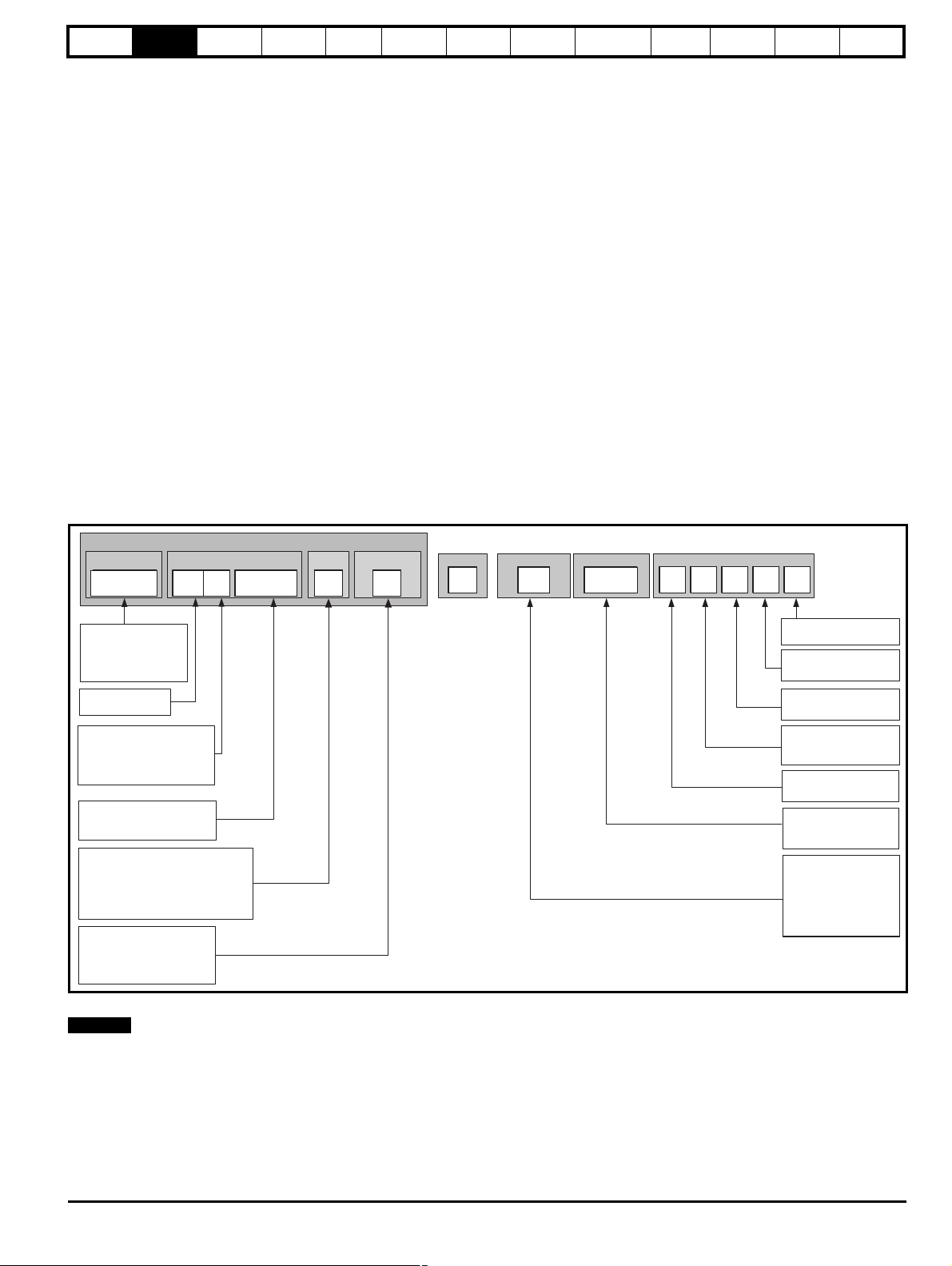
2.3 Model number
The way in which the model numbers for the Unidrive M600 range are formed is illustrated below:
Figure 2-1 Model number
* Only shown on Frame 9 to 11 identification label.
For simplicity, a Frame 9 drive with no internal choke (i.e. model 09xxxxxxE) is referred to as a Frame 9E and a Frame 9 drive with an internal choke
(i.e. model 09xxxxxxA) is referred to as a Frame 9A. Any reference to Frame 9 is applicable to both sizes 9E and 9A.
Unidri ve M600 Control User Guide 11
Issue Number: 2
Safety
Available output
current
Overload limit -
Heavy Duty
Maximum
continuous
current (above
50% base
speed) -
Normal Duty
Maximum
continuous
current -
Heavy Duty
Motor rated
current set
in the drive
Heavy Duty
- with high
overload capability
Normal Duty
Overload limit -
Normal Duty
NOTE
NOTE
Motor total
current (Pr 04.001)
as a percentage
of motor rated
current
Motor speed as a
percentage of base speed
100%
Max. permissible
continuous
current
100%
I t protection operates in this region
2
70%
50%15%
Pr = 0
Pr = 1
04.025
04.025
Motor total
current (Pr 04.001)
as a percentage
of motor rated
current
Motor speed as a
percentage of base speed
100%
Max. permissible
continuous
current
100%
I t protection operates in this region
2
70%
50%
Pr = 0
Pr = 1
04.025
04.025
information
Product
information
Mechanical
installation
Electrical
installation
Getting
started
Basic
parameters
Running the
motor
Optimization
NV Media Card
Operation
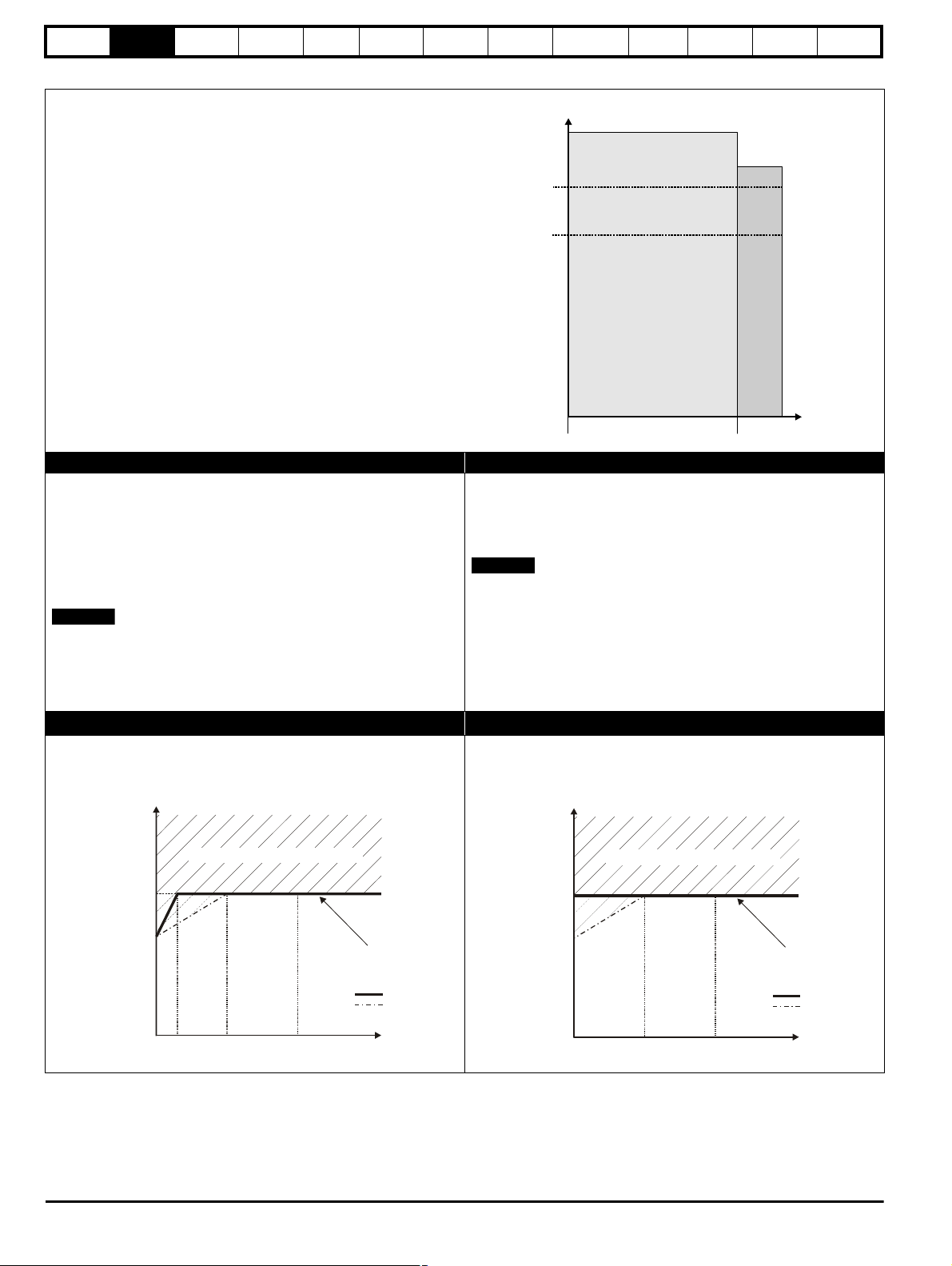
2.4 Ratings
The drive is dual rated.
The setting of the motor rated current determines which rating applies Heavy Duty or Normal Duty.
The two ratings are compatible with motors designed to IEC60034.
The graph aside illustrates the difference between Normal Duty and
Heavy Duty with respect to continuous current rating and short term
overload limits.
Normal Duty Heavy Duty (default)
For applications which use Self ventilated (TENV/TEFC) induction
motors and require a low overload capability, and full torque at low
speeds is not required (e.g. fans, pumps).
Self ventilated (TENV/TEFC) induction motors require increased
protection against overload due to the reduced cooling effect of the fan
at low speed. To provide the correct level of protection the I
2
t software
operates at a level which is speed dependent. This is illustrated in the
graph below.
The speed at which the low speed protection takes effect can be
changed by the setting of Low Speed Thermal Protection Mode
(04.025). The protection starts when the motor speed is below 15 % of
base speed when Pr 04.025 = 0 (default) and below 50 % when
Pr 04.025 = 1.
Operation of motor I2t protection
Motor I2t protection is fixed as shown below and is compatible with:
• Self ventilated (TENV/TEFC) induction motors
For constant torque applications or applications which require a high
overload capability, or full torque is required at low speeds (e.g. winders,
hoists).
The thermal protection is set to protect force ventilated induction motors
and permanent magnet servo motors by default.
N
If the application uses a self ventilated (TENV/TEFC) induction motor
and increased thermal protection is required for speeds below 50 %
base speed, then this can be enabled by setting Low Speed Thermal
Protection Mode (04.025) = 1.
Motor I2t protection defaults to be compatible with:
• Forced ventilation induction motors
• Permanent magnet servo motors
Onboard
PLC
Advanced
parameters
Diagnostics
UL
Information
.
12 Unidrive M600 Control User Guide
Issue Number: 2

Safety
information
Product
information
Mechanical
installation
Electrical
installation
Getting
started
Basic
parameters
Running the
motor
Optimization
NV Media Card
Operation
Onboard
PLC
Advanced
parameters
Diagnostics
UL
Information
2.5 Operating modes
The drive is designed to operate in any of the following modes:
Open loop mode
Open loop vector mode
Fixed V/F mode (V/Hz)
Quadratic V/F mode (V/Hz)
RFC - A
With position feedback sensor (requires optional SI-Encoder module)
Without position feedback sensor (Sensorless)
RFC - S
Without position feedback sensor (Sensorless)
Regen mode
2.5.1 Open loop mode
The drive applies power to the motor at frequencies varied by the user. The motor speed is a result of the output frequency of the drive and slip due
to the mechanical load. The drive can improve the speed control of the motor by applying slip compensation. The performance at low speed depends
on whether V/F mode or open loop vector mode is selected.
Open loop vector mode
The voltage applied to the motor is directly proportional to the frequency except at low speed where the drive uses motor parameters to apply the
correct voltage to keep the flux constant under varying load conditions.
Typically 100 % torque is available down to 1 Hz for a 50 Hz motor.
Fixed V/F mode
The voltage applied to the motor is directly proportional to the frequency except at low speed where a voltage boost is provided which is set by the
user. This mode can be used for multi-motor applications.
Typically 100 % torque is available down to 4 Hz for a 50 Hz motor.
Quadratic V/F mode
The voltage applied to the motor is directly proportional to the square of the frequency except at low speed where a voltage boost is provided which is
set by the user. This mode can be used for running fan or pump applications with quadratic load characteristics or for multi-motor applications. This
mode is not suitable for applications requiring a high starting torque.
2.5.2 RFC-A mode
Rotor Flux Control for Asynchronous (induction) motors (RFC-A) encompasses closed loop vector control with and without a position feedback
device.
With position feedback (requires optional SI-Encoder module)
For use with induction motors with a feedback device installed. The drive directly controls the speed of the motor using the feedback device to ensure
the rotor speed is exactly as demanded. Motor flux is accurately controlled at all times to provide full torque all the way down to zero speed.
Without position feedback (Sensorless)
Sensorless mode provides closed loop control without the need for position feedback by using current, voltages and key operating motor parameters
to estimate the motor speed. It can eliminate instability traditionally associated with open loop control such as operating large motors with light loads
at low frequencies.
2.5.3 RFC- S
Rotor Flux Control for Synchronous (permanent magnet brushless) motors (RFC-S) provides closed loop control without a position feedback device.
Without position feedback
For use with permanent magnet brushless motors without a feedback device installed.
Flux control is not required because the motor is self excited by the permanent magnets which form part of the rotor.
Full torque is available all the way down to zero speed, with salient motors.
2.5.4 Regen mode
For use as a regenerative front end for four quadrant operation.
Regen operation allows bi-directional power flow to and from the AC supply. This provides far greater efficiency levels in applications which would
otherwise dissipate large amounts of energy in the form of heat in a braking resistor.
The harmonic content of the input current is negligible due to the sinusoidal nature of the waveform when compared to a conventional bridge rectifier
or SCR/thyristor front end.
Unidri ve M600 Control User Guide 13
Issue Number: 2
Safety
Refer to
User Guide
Model
Frame
size
Voltage
Heavy Duty
current rating
Drive format
M600-032 00050 A
Approvals
Output
voltage
Heavy Duty /
Normal Duty
power rating
Date code
Serial
number
Input
frequency
No.of phases &
Typical input current for
Normal Duty rating
Heavy Duty /
Normal Duty rating
output current
1710
M600-074-00660-A30/37kW 1710
I/P 380-480V 50-60Hz 3ph 74A
O/P 0-480V 3ph 66/79A
Designed in UK
Made in U.K.
Serial No: 3000005001
No. of Input phase &
Input current
No. of Output phase
&
Output current
Heavy Duty/
Normal Duty Rating
Model
Input
frequency
Heavy Duty /
Normal Duty
power rating
Date code
Approvals
Serial number
Input
voltage
Output
voltage
Large label*
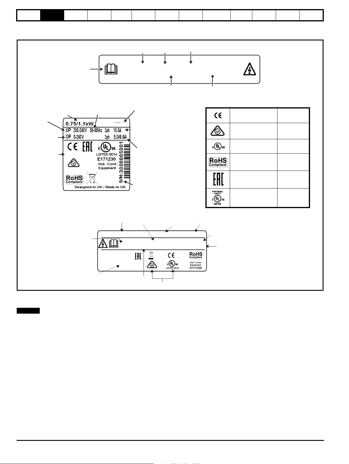
Key to approvals
CE approval Europe
RCM - Regulatory
Compliance Mark
Australia
UL / cUL approval
USA &
Canada
RoHS compliant Europe
Eurasian conformity Eurasia
Functional safety
USA &
Canada
R
NOTE
information
Product
information
Mechanical
installation
Electrical
installation
2.6 Nameplate description
Figure 2-2 Typical drive rating labels
Getting
started
Basic
parameters
Running the
motor
Optimization
NV Media Card
Operation
Onboard
PLC
Advanced
parameters
Diagnostics
UL
Information
* This label is only applicable to Size 7 and above.
Refer to Figure 2-1 Model number on page 11 for further information relating to the labels.
Date code format
The date code is four numbers. The first two numbers indicate the year and the remaining numbers indicate the week of the year in which the drive
was built.
Example:
A date code of 1710 would correspond to week 10 of year 2017.
14 Unidrive M600 Control User Guide
Issue Number: 2
Safety
8
WARN ING
information
Product
information
Mechanical
installation
Electrical
installation
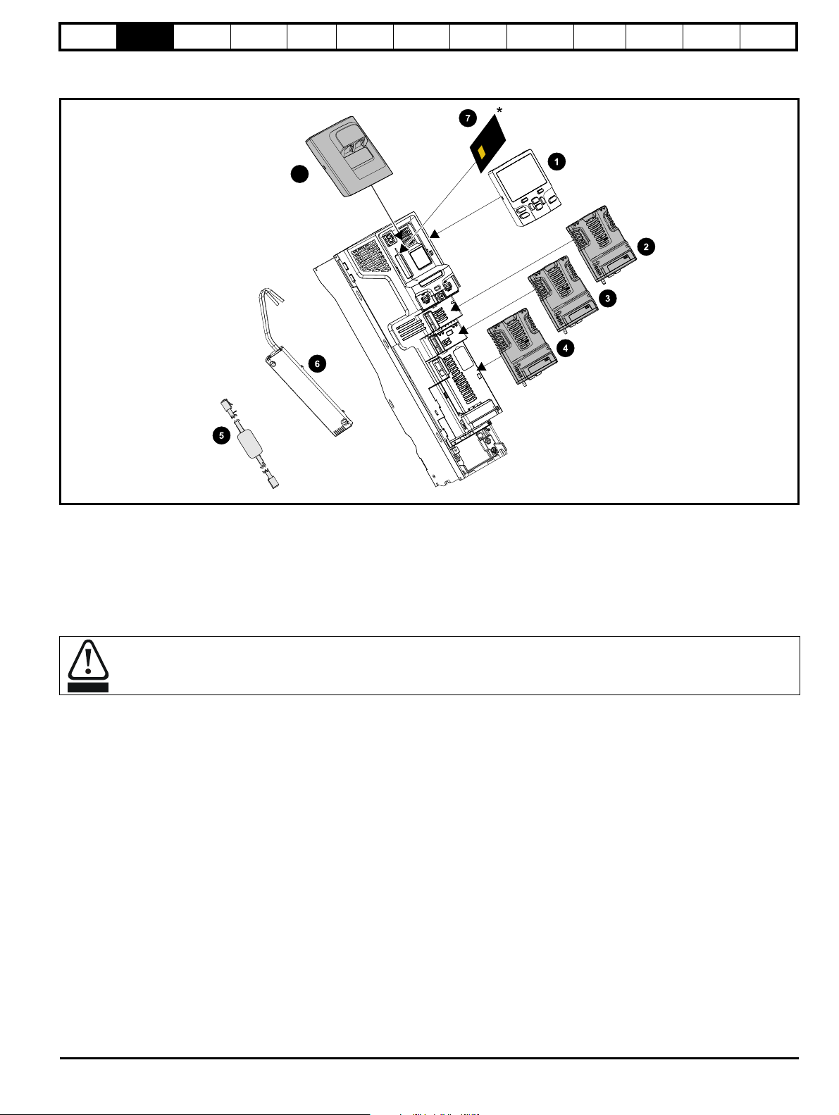
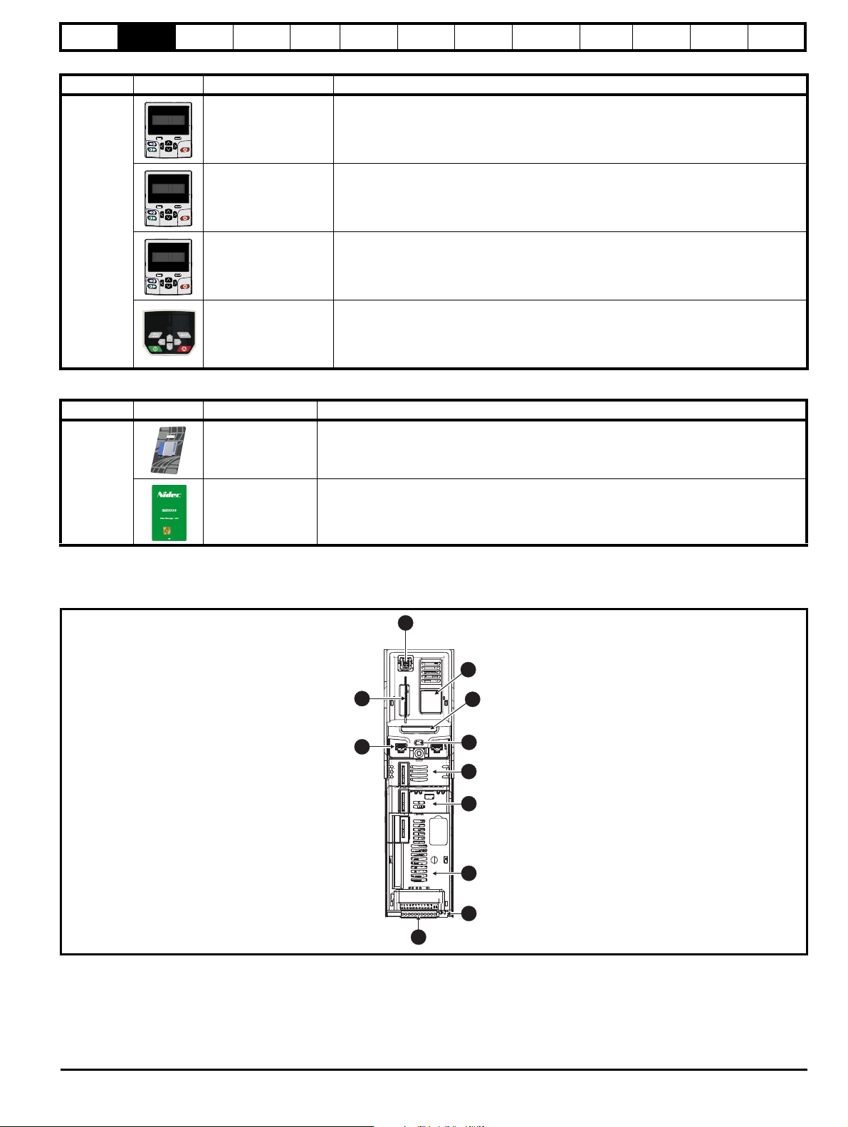
2.7 Options
Figure 2-3 Options available with the drive
Getting
started
Basic
parameters
Running the
motor
Optimization
NV Media Card
Operation
Onboard
PLC
Advanced
parameters
Diagnostics
UL
Information
1. Keypad
2. Option module slot 1
3. Option module slot 2
4. Option module slot 3
5. CT USB Comms cable
6. Internal braking resistor
7. NV media card (* For further information refer to chapter 8 NV Media Card Operation on page 99).
8. KI-485 comms adaptor
Be aware of possible live terminals when inserting or removing the NV media card.
Unidri ve M600 Control User Guide 15
Issue Number: 2
Safety
information
Product
information
Mechanical
installation
Electrical
installation
Getting
started
Basic
parameters
Running the
motor
Optimization
NV Media Card
Operation
Onboard
PLC
Advanced
parameters
Diagnostics
UL
Information
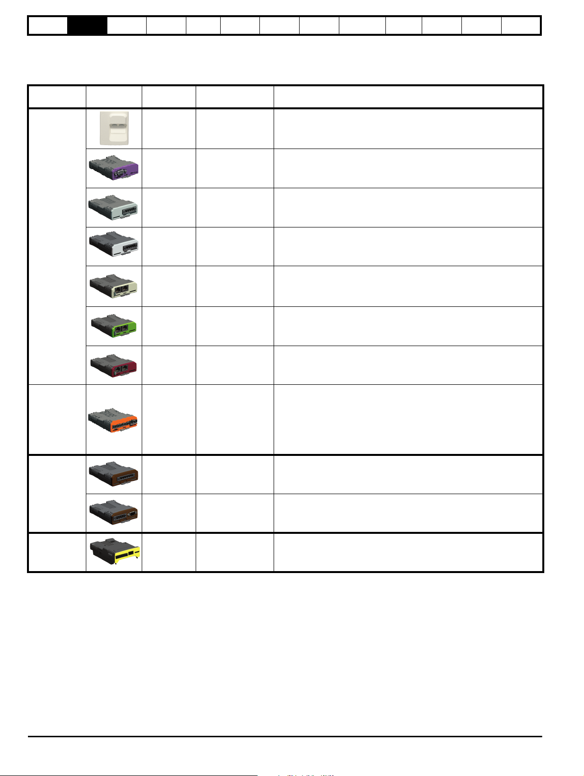
All standard option modules are color-coded in order to make identification easy. All modules have an identification label on top of the module.
Standard option modules can be installed to any of the available option slots on the drive. The following tables shows the color-code key and gives
further details on their function.
Table 2-1 Option module identification
Typ e
Option
module
Color Name Further Details
EIA 485 Comms Adaptor
N/A KI-485 Adaptor
EIA 485 Comms adaptor provides EIA 485 communication interface. This
adaptor supports 115 k Baud, node addresses between 1 to 16 and 8 1 NP M
serial mode.
Fieldbus
Automation
(I/O expansion)
Purple SI-PROFIBUS
Medium Grey SI-DeviceNet
Light Grey SI-CANopen
Beige SI-Ethernet
Yellow Green SI-PROFINET V2
Brown Red SI-EtherCAT
Orange SI-I/O
PROFIBUS option
PROFIBUS adapter for communications with the drive
DeviceNet option
DeviceNet adapter for communications with the drive
CANopen option
CANopen adapter for communications with the drive
External Ethernet module that supports EtherNet/IP, Modbus TCP/IP and
RTMoE. The module can be used to provide high speed drive access, global
connectivity and integration with IT network technologies, such as wireless
networking
PROFINET V2 option
PROFINET V2 adapter for communications with the drive
Note: PROFINET V2 replaces PROFINET RT.
EtherCAT option
EtherCAT adapter for communications with the drive
Extended I/O
Increases the I/O capability by adding the following combinations:
• Digital I/O
• Digital Inputs
• Analog Inputs (differential or single ended)
• Analog Output
• Relays
Light Brown SI-Encoder
Incremental encoder input interface module. Provides Closed loop Rotor
Flux Control for induction motors (RFC-A) on M600.
Feedback
Dark Brown SI-Universal Encoder
Safety Yellow SI-Safety
Additional combined encoder input and output interface supporting
Incremental, SinCos, HIPERFACE, EnDAT and SSI encoders.
Safety module that provides an intelligent, programmable solution to meet
the IEC 61800-5-2 functional safety standard
16 Unidrive M600 Control User Guide
Issue Number: 2
Safety
1
2
3
4
5
6
7
8
9
10
11
information
Product
information
Mechanical
installation
Electrical
installation
Getting
started
Basic
parameters
Running the
motor
Optimization
NV Media Card
Operation
Table 2-2 Keypad identification
Type Keypad Name Further Details
Onboard
PLC
Advanced
parameters
Diagnostics
UL
Information
KI-Keypad
LCD keypad option
Keypad with an LCD display
KI-Keypad RTC LCD keypad option
Keypad with an LCD display and real time clock
Keypad
Remote-Keypad RTC
Remote-Keypad
Remote LCD keypad option
Remote Keypad with an LCD display and real time clock
Remote LCD keypad option
Remote Keypad with an LCD display.
Table 2-3 Additional options
Type Option Name Further Details
SD Card Adaptor
SD Card Adaptor
Allows the drive to use an SD card for drive back-up
Back-up
SMARTCARD
SMARTCARD
Used for parameter back-up with the drive
2.8 Drive features
Figure 2-4 Features of the drive control section
Key
1. Keypad connection
4. Status LED 5. Option module slot 1 6. Option module slot 2
7. Option module slot 3 8. Relay connections 9. Control connections
10. Communications port 11. NV media card slot
2. Rating label 3. Identification label
Unidri ve M600 Control User Guide 17
Issue Number: 2
Safety
CAUTION
NOTE
information
Product
information
Mechanical
installation
Electrical
installation
Getting
started
Basic
parameters
Running the
motor
Optimization
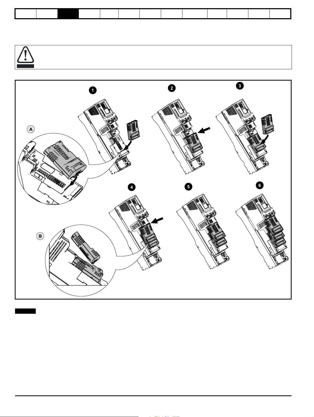
3 Mechanical installation
3.1 Installing / removing option modules and keypads
Power down the drive before installing / removing the option module. Failure to do so may result in damage to the product.
Figure 3-1 Installation of an option module
NV Media Card
Operation
Onboard
PLC
Advanced
parameters
Diagnostics
UL
Information
Installing the first option module
Option module slots must be used in the following order: slot 3, slot 2 and slot 1 (refer to Figure 2-3 Options available with the drive on page 15 for
slot numbers).
• Move the option module in direction shown (1).
• Align and insert the option module tab in to the slot provided (2), this is highlighted in the detailed view (A).
• Press down on the option module until it clicks into place.
Installing the second option module
• Move the option module in direction shown (3).
• Align and insert the option module tab in to the slot provided on the already installed option module (4), this is highlighted in the detailed view (B).
• Press down on the option module until it clicks into place. Image (5) shows two option modules fully installed.
Installing the third option module
• Repeat the above process.
The drive has the facility for all three option module slots to be used at the same time, image (6) shows the three option modules installed.
18 Unidrive M600 Control User Guide
Issue Number: 2
Safety
NOTE
information
Product
information
Mechanical
installation
Electrical
installation
Getting
started
Basic
parameters
Running the
motor
Optimization
NV Media Card
Operation
Onboard
PLC
Advanced
parameters
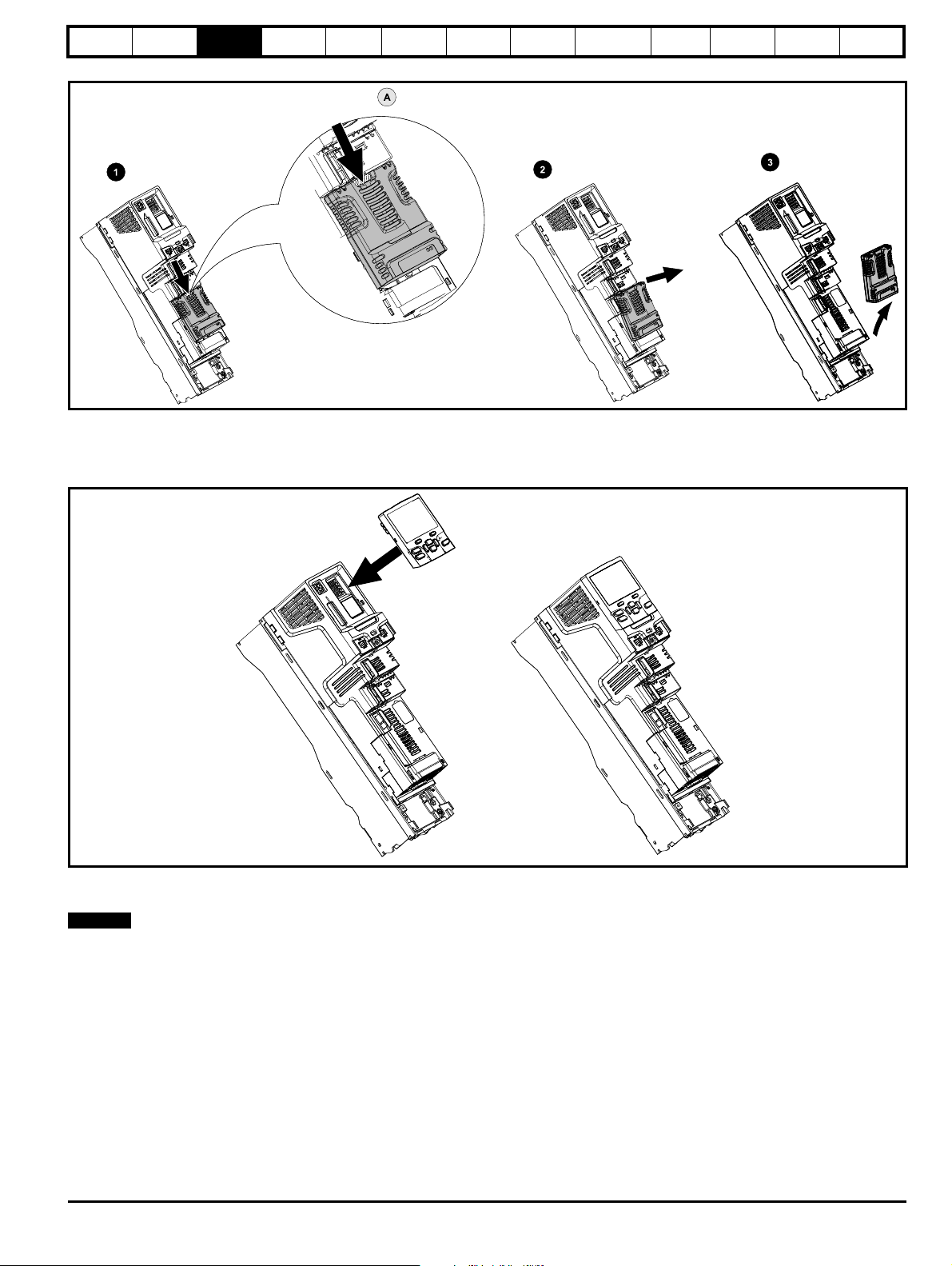
Figure 3-2 Removal of an option module
• Press down on the tab (1) to release the option module from the drive housing, the tab is highlighted in the detailed view (A).
• Tilt the option module towards you as shown (2).
• Totally remove the option module in direction shown (3).
Figure 3-3 Installation and removal of the KI-Keypad
Diagnostics
UL
Information
To install, align the keypad and press gently in the direction shown until it clicks into position.
To remove, reverse the installation instructions.
N
The keypad can be installed / removed while the drive is powered up and running a motor, providing that the drive is not operating in keypad mode.
Unidrive M600 Control User Guide 19
Issue Number: 2
Safety
NOTE
information
Product
information
Mechanical
installation
Electrical
installation
Getting
started
Basic
parameters
Running the
motor
Optimization
NV Media Card
Operation
Onboard
PLC
Advanced
parameters
Diagnostics
UL
Information
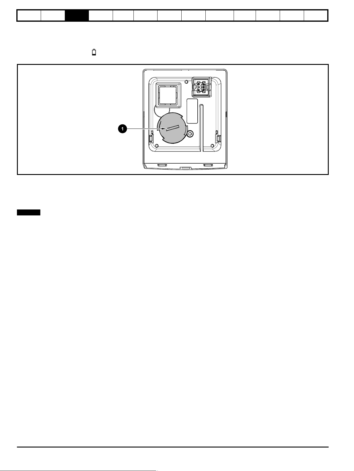
3.1.1 Real time clock battery replacement
Those keypads which have the real time clock feature contain a battery to ensure the clock works when the drive is powered down. The battery has a
long life time but if the battery needs to be replaced or removed, follow the instructions below.
Low battery voltage is indicated by
low battery symbol on the keypad display.
Figure 3-4 KI-Keypad RTC (rear view)
Figure 3-4 above illustrates the rear view of the KI-Keypad RTC.
1. To remove the battery cover insert a flat head screwdriver into the slot as shown (1), push and turn anti-clockwise until the battery cover is
released.
2. Replace the battery (the battery type is: CR2032).
3. Reverse point 1 above to replace battery cover.
Ensure the battery is disposed of correctly.
20 Unidrive M600 Control User Guide
Issue Number: 2
Safety
NOTE
515251
52
51 5251
52
51 5251
52
information
Product
information
Mechanical
installation
Electrical
installation
Getting
started
Basic
parameters
Running the
motor
Optimization
NV Media Card
Operation
Onboard
PLC
Advanced
parameters
Diagnostics
UL
Information
4 Electrical installation
4.1 24 Vdc supply
The 24 Vdc supply connected to control terminals 1 & 2 provides the
following functions:
• It can be used to supplement the drive's own internal 24 V supply
when multiple option modules are being used and the current drawn
by these module is greater than the drive can supply.
• It can be used as a back-up power supply to keep the control circuits
of the drive powered up when the line power supply is removed. This
allows any fieldbus modules, application modules, encoders or serial
communications to continue to operate.
• It can be used to commission the drive when the line power supply is
not available, as the display operates correctly. However, the drive
will be in the Under voltage state unless either line power supply or
low voltage DC operation is enabled, therefore diagnostics may not
be possible. (Power down save parameters are not saved when
using the 24 V back-up power supply input).
• If the DC bus voltage is too low to run the main SMPS in the drive,
then the 24 V supply can be used to supply all the low voltage power
requirements of the drive. Low Under Voltage Threshold Select
(06.067) must also be enabled for this to happen.
On size 6 and larger, the power 24 Vdc supply (terminals 51, 52) must
be connected to enable the 24 Vdc supply to be used as a backup
supply, when the line power supply is removed. If the power 24 Vdc
supply is not connected none of the above mentioned functions can be
used, "Waiting For Power System" will be displayed on the keypad and
no drive operations are possible. The location of the power 24 Vdc can
be identified from Figure 4-1 Location of the 24 Vdc power supply
connection on size 6 on page 21.
Table 4-1 24 Vdc Supply connections
The working voltage range of the control 24 V power supply is as
follows:
Nominal operating voltage 24.0 Vdc
Minimum continuous operating voltage 19.2 V
Maximum continuous operating voltage 28.0 V
Minimum start up voltage 21.6 V
Maximum power supply requirement at 24 V 40 W
Recommended fuse 3 A, 50 Vdc
Minimum and maximum voltage values include ripple and noise. Ripple
and noise values must not exceed 5 %.
Function Sizes 3-5 Sizes 6-11
Supplement the drive’s
internal supply
Back-up supply for the
control circuit
Terminal
1, 2
Terminal
1, 2
1 0V common
2 +24 Vdc
Terminal
1, 2
Terminal
1, 2
51, 52
The working range of the 24 V power supply is as follows:
51 0V common
52 +24 Vdc
Size 6
Nominal operating voltage 24.0 Vdc
Minimum continuous operating voltage 18.6 Vdc
Maximum continuous operating voltage 28.0 Vdc
Minimum startup voltage 18.4 Vdc
Maximum power supply requirement 40 W
Recommended fuse 4 A @ 50 Vdc
Size 7 to 11
Nominal operating voltage 24.0 Vdc
Minimum continuous operating voltage 19.2 Vdc
Maximum continuous operating voltage
30 Vdc (IEC),
26 Vdc (UL)
Minimum startup voltage 21.6 Vdc
Maximum power supply requirement 60 W
Recommended fuse 4 A @ 50 Vdc
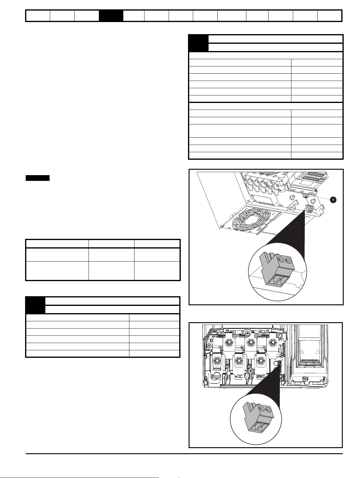
Figure 4-1 Location of the 24 Vdc power supply connection on size 6
1. 24 Vdc power supply connection
Figure 4-2 Location of the 24 Vdc power supply connection on size 7
Unidrive M600 Control User Guide 21
Issue Number: 2
Safety
51 5251
52
1 1
8
8
NOTE
CAUTION
WARNING
information
Product
information
Mechanical
installation
Electrical
installation
Getting
started
Basic
parameters
Running the
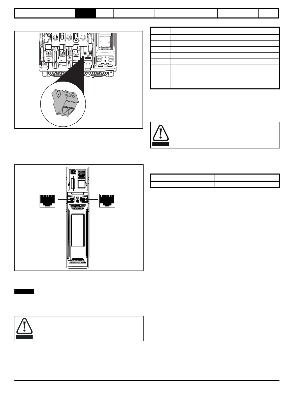
Figure 4-3 Location of the 24 Vdc power supply connection on size 8
to 11
4.2 Communication connections
The drive offers a 2 wire EIA 485 interface. This enables the drive setup, operation and monitoring to be carried out with a PC or controller if
required.
Figure 4-4 Location of the comms connectors
motor
Optimization
NV Media Card
Operation
Onboard
PLC
Advanced
parameters
Diagnostics
Table 4-2 Serial communication port pin-outs
Pin Function
1 120 Ω Termination resistor
2RX TX
3 Isolated 0 V
4 +24 V (100 mA)
5 Isolated 0 V
6 TX enable
7RX\ TX\
8 RX\ TX\ (if termination resistors are required, link to pin 1)
Shell Isolated 0 V
Minimum number of connections are 2, 3, 7 and shield.
4.2.1 Isolation of the EIA 485 serial communications port
The serial PC communications port is double insulated and meets the
requirements for SELV in EN 50178:1998.
In order to meet the requirements for SELV in IEC60950 (IT
equipment) it is necessary for the control computer to be
grounded. Alternatively, when a lap-top or similar device is
used which has no provision for grounding, an isolation
device must be incorporated in the communications lead.
An isolated serial communications lead has been designed to connect
the drive to IT equipment (such as laptop computers), and is available
from the supplier of the drive. See below for details:
Table 4-3 Isolated serial comms lead details
Part number Description
4500-0096 CT USB Comms cable
The “isolated serial communications” lead has reinforced insulation as
defined in IEC60950 for altitudes up to 3,000 m.
4.2.2 Communication networks and cabling
Any isolated signal circuit has the capability to become live through
accidental contact with other conductors; as such they should always be
double-insulated from live parts. The routing of network and signal wires
should be done so as to avoid close proximity to mains voltage cabling.
UL
Information
The EIA 485 interface provides two parallel RJ45 connectors, these are
provided allowing easy daisy chaining. The drive only supports Modbus
RTU protocol. See Table 4-2 for the connection details.
Standard Ethernet cables are not recommended for use when
connecting drives on a EIA 485 network as they do not have the correct
twisted pairs for the pinout of the serial comms port.
If an Ethernet network adaptor is inadvertently connected to
a Unidrive M600 drive, a low impedance load across the EIA
485 24V is applied. If this is connected for a significant period
of time, it can introduce the potential risk of damage.
22 Unidrive M600 Control User Guide
Issue Number: 2
Safety
WARNING
WARNING
CAUTION
CAUTION
NOTE
NOTE
NOTE
NOTE
Analog Input 1+
Analog Input 3
0V
Analog Input 1-
5
8
11
6
information
Product
information
Mechanical
installation
Electrical
installation
Getting
started
Basic
parameters
Running the
4.3 Control connections
4.3.1 General
Table 4-4 The control connections consist of:
Function Qty
Control parameters
available
Differential analog input 1 Mode, offset, invert, scaling 5, 6
Single ended analog
input
Mode, offset, invert, scaling,
2
destination
Analog output 2 Source, scaling, 9, 10
Digital input 3
Destination, invert, logic
select
Input / output mode select,
Digital input / output 3
destination / source, invert,
logic select
Relay 1 Source, invert 41, 42
Drive enable (Safe
Tor q u e O ff )
131
+10 V User output 1 4
+24 V User output 1 Source, invert 22
0V common 6
+24V External input 1 Destination, invert 2
Key:
Destination parameter:
Source parameter:
Indicates the parameter which is being controlled
by the terminal / function
Indicates the parameter being output by the
terminal
Analog - indicates the mode of operation of the
terminal, i.e. voltage 0-10 V, current 4-20 mA etc.
Mode parameter:
Digital - indicates the mode of operation of the
terminal, i.e. positive / negative logic (the Drive
Enable terminal is fixed in positive logic), open
collector.
All analog terminal functions can be programmed in menu 7.
All digital terminal functions (including the relay) can be programmed in
menu 8.
The control circuits are isolated from the power circuits in the
drive by basic insulation (single insulation) only. The installer
must ensure that the external control circuits are insulated
from human contact by at least one layer of insulation
(supplementary insulation) rated for use at the AC supply
voltage.
Ter mina l
number
7, 8
27, 28, 29
24, 25, 26
1, 3, 11, 21,
23, 30
motor
Optimization
NV Media Card
Operation
Onboard
PLC
Advanced
parameters
Diagnostics
ground close to the point of exit of the motor cable, to avoid this noise
current spreading through the control system.
N
The Safe Torque Off drive enable terminal is a positive logic input only. It
is not affected by the setting of Input Logic Polarity (08.029).
N
The common 0 V from analog signals should, wherever possible, not be
connected to the same 0 V terminal as the common 0 V from digital
signals. Terminals 3 and 11 should be used for connecting the 0V
common of analog signals and terminals 21, 23 and 30 for digital
signals. This is to prevent small voltage drops in the terminal
connections causing inaccuracies in the analog signals.
N
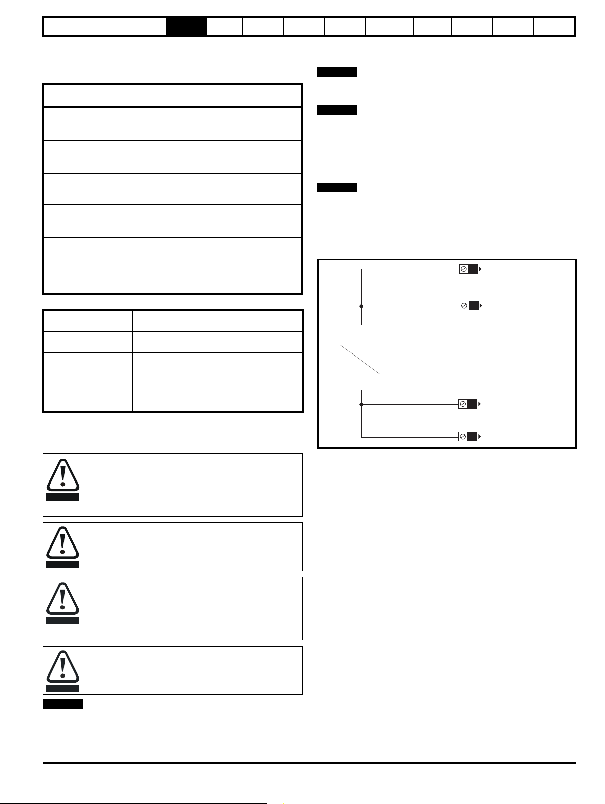
A two wire motor thermistor can be connected to analog input 3 by
connecting the thermistor between terminal 8 and any 0 V common
terminal. It is also possible to connect a 4-wire thermistor to analog input
3 as shown below. Pr 07.015 and Pr 07.046 need to be set-up for the
thermistor type required.
Figure 4-5 Connection of 4-wire thermistor
UL
Information
If the control circuits are to be connected to other circuits
classified as Safety Extra Low Voltage (SELV) (e.g. to a
personal computer), an additional isolating barrier must be
included in order to maintain the SELV classification.
If any of the digital inputs (including the drive enable input)
are connected in parallel with an inductive load (i.e.
contactor or motor brake) then suitable suppression (i.e.
diode or varistor) should be used on the coil of the load. If no
suppression is used then over voltage spikes can cause
damage to the digital inputs and outputs on the drive.
Ensure the logic sense is correct for the control circuit to be
used. Incorrect logic sense could cause the motor to be
started unexpectedly.
Positive logic is the default state for the drive.
N
Any signal cables which are carried inside the motor cable (i.e. motor
thermistor, motor brake) will pick up large pulse currents via the cable
capacitance. The shield of these signal cables must be connected to
Unidrive M600 Control User Guide 23
Issue Number: 2
Safety
1
11
Polarized
connectors
21 31
41
42
0V common**
External 24V supply
0V common**
Analog frequency/speed
reference 1
Connections for
single-ended input
signal
Connections for
differential input signal
0V common**
0V common**
0V common**
Analog input 2
Analog input 1
0V common**
1
2
5
6
3
5
6
3
21
22
23
24
25
26
27
28
29
30
31
41
42
At zero speed
Reset
Run forward
Run reverse
Analog input 1/
input 2 select
Jog forward select
SAFE TORQUE OFF /
Drive enable*
Relay
(Over voltage
category II)
Drive OK
Speed / frequency
0V common**
Analog
frequency/speed
reference 2
4
7
11
9
10
8
Torque (active
current)
Analog input 3
information
Product
information
Mechanical
installation
Electrical
installation
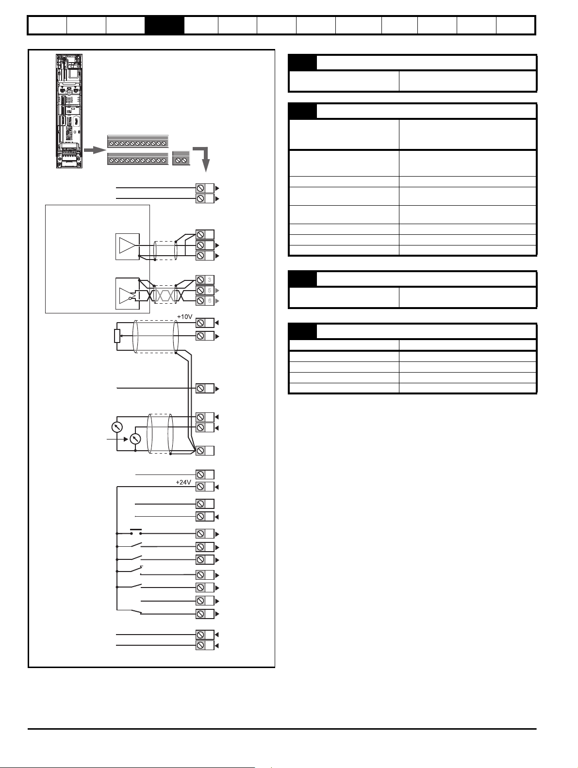
Figure 4-6 Default terminal functions
Getting
started
Basic
parameters
Running the
motor
Optimization
NV Media Card
Operation
Onboard
PLC
4.3.2 Control terminal specification
1 0V common
Function
2 +24V external input
Function
Programmability
Nominal voltage +24.0 Vdc
Minimum continuous operating
voltage
Maximum continuous operating
voltage
Minimum start-up voltage 21.6 Vdc
Recommended power supply 40 W 24 Vdc nominal
Recommended fuse 3 A, 50 Vdc
Advanced
parameters
Diagnostics
UL
Information
Common connection for all external
devices
To supply the control circuit
without providing a supply to the
power stage
Can be switched on or off to act as a digital
input by setting the source Pr 08.063 and
input invert Pr 08.053
+19.2 Vdc
+28.0 Vdc
3 0V common
Function
Common connection for all external
devices
4 +10V user output
Function Supply for external analog devices
Voltage 10.2 V nominal
Voltage tolerance ±1 %
Nominal output current 10 mA
*The Safe Torque Off / Drive enable terminal is a positive logic input only.
** 0V common is connected to ground internally in size 9 to 11 modular
drives.
Protection Current limit and trip @ 30 mA
24 Unidrive M600 Control User Guide
Issue Number: 2
Safety
information
Product
information
Mechanical
installation
Electrical
installation
Getting
started
Basic
parameters
Running the
motor
Optimization
NV Media Card
Operation
Onboard
PLC
Advanced
parameters
Diagnostics
UL
Information
4 Precision reference Analog input 1
5 Non-inverting input
6 Inverting input
Default function Frequency/speed reference
Type of input
Mode controlled by: Pr 07.007
Operating in Voltage mode
Full scale voltage range ±10 V ±2 %
Maximum offset ±10 mV
Absolute maximum
voltage range
Working common mode voltage
range
Input resistance ≥100 kΩ
Monotonic Yes (including 0 V)
Dead band None (including 0 V)
Jumps None (including 0 V)
Maximum offset 20 mV
Maximum non linearity 0.3% of input
Maximum gain asymmetry 0.5 %
Input filter bandwidth single pole ~3 kHz
Operating in current mode
Current ranges
Maximum offset 250 μA
Absolute maximum voltage
(reverse biased)
Equivalent input resistance ≤300 Ω
Absolute maximum current ±30 mA
Operating in thermistor input mode (in conjunction with analog input 3)
Internal pull-up voltage 2.5 V
Trip threshold resistance User defined in Pr 07.048
Short-circuit detection resistance 50 Ω ± 40 %
Common to all modes
Resolution 12 bits (11 bits plus sign)
Sample / update period
Bipolar differential analog voltage or
current, thermistor input
±36 V relative to 0 V
±13 V relative to 0 V
0 to 20 mA ±5 %, 20 to 0 mA ±5 %,
4 to 20 mA ±5 %, 20 to 4 mA ±5 %
±36 V relative to 0 V
250 µs with destinations Pr 01.036,
Pr 01.037, Pr 03.022 or Pr 04.008 in RFC-A
and RFC-S modes. 4 ms for open loop
mode and all other destinations in RFC-A or
RFC-S modes.
7 Analog input 2
Default function Frequency / speed reference
Type of input
Mode controlled by... Pr 07.011
Bipolar single-ended analog voltage or
unipolar current
Operating in voltage mode
Full scale voltage range ±10 V ±2 %
Maximum offset ±10 mV
Absolute maximum voltage range ±36 V relative to 0 V
Input resistance
≥100 k Ω
Operating in current mode
Current ranges
Maximum offset 250 μA
Absolute maximum voltage
(reverse bias)
Absolute maximum current ±30 mA
Equivalent input resistance ≤ 300 Ω
0 to 20 mA ±5 %, 20 to 0 mA ±5 %,
4 to 20 mA ±5 %, 20 to 4 mA ±5 %
±36 V relative to 0V
Common to all modes
Resolution 12 bits (11 bits plus sign)
250 µs with destinations Pr 01.036,
Sample / update
Analog input 3
8
Pr 01.037 or Pr 03.022, Pr 04.008 in RFC-A
or RFC-S. 4ms for open loop mode and all
other destinations in RFC-A or RFC-S
mode.
Default function Voltage input
Type of input
Mode controlled by... Pr 07.015
Bipolar single-ended analog voltage, or
thermistor input
Operating in Voltage mode (default)
Voltage range ±10 V ±2 %
Maximum offset ±10 mV
Absolute maximum voltage range ±36 V relative to 0 V
Input resistance ≥100 k Ω
Operating in thermistor input mode
Supported thermistor types
Internal pull-up voltage 2.5 V
Trip threshold resistance User defined in Pr 07.048
Reset resistance User defined in Pr 07.048
Short-circuit detection resistance 50 Ω ± 40 %
Din 44082, KTY 84, PT100, PT 1000,
PT 2000, 2.0mA
Common to all modes
Resolution 12 bits (11 bits plus sign)
Sample / update period 4 ms
Unidrive M600 Control User Guide 25
Issue Number: 2
Safety
information
Product
information
Mechanical
installation
Electrical
installation
Getting
started
Basic
parameters
9 Analog output 1
10 Analog output 2
OL> Motor FREQUENCY output
Terminal 9 default function
signal
RFC> SPEED output signal
Terminal 10 default function Motor active current
Type of output Bipolar single-ended analog voltage
Operating in Voltage mode (default)
Voltage range ±10 V ±5 %
Maximum offset ±120 mV
Maximum output current ±20 mA
Load resistance ≥1 k Ω
Protection 20 mA max. Short circuit protection
Common to all modes
Resolution 10-bit
Sample / update period
250 µs (output will only change at update
the rate of the source parameter if slower)
11 0V common
Function
Common connection for all external
devices
Running the
motor
Optimization
NV Media Card
Operation
Onboard
PLC
Advanced
parameters
Diagnostics
UL
Information
24 Digital I/O 1
Digital I/O 2
25
26 Digital I/O 3
Terminal 24 default function AT ZERO SPEED output
Terminal 25 default function DRIVE RESET input
Terminal 26 default function RUN FORWARD input
Type
Input / output mode controlled by... Pr 08.031, Pr 08.032 and Pr 08.033
Positive or negative logic digital inputs,
positive logic voltage source outputs
Operating as an input
Logic mode controlled by... Pr 08.029
Absolute maximum applied
voltage range
Impedance >2 mA @15 V (IEC 61131-2, type 1, 6.6 k Ω)
Input thresholds 10 V ±0.8 V (IEC 61131-2, type 1)
-3 V to +30 V
Operating as an output
100 mA (DIO1 & 2 combined)
Nominal maximum output current
Maximum output current
100 mA (DIO3 & 24 V User Output
Combined)
100 mA
200 mA (total including all Digital I/O)
Common to all modes
Voltage range 0 V to +24 V
Sample / Update period
2 ms (output will only change at the update
rate of the source parameter)
21 0V common
Function
Common connection for all external
devices
22 +24 V user output (selectable)
Terminal 22 default function +24 V user output
Can be switched on or off to act as a fourth
Programmability
Nominal output current 100 mA combined with DIO3
Maximum output current
Protection Current limit and trip
Sample / update period
digital output (positive logic only) by setting
the source Pr 08.028 and source invert
Pr 08.018
100 mA
200 mA (total including all Digital I/O)
2 ms when configured as an output (output
will only change at the update rate of the
source parameter if slower)
23 0V common
Function
Common connection for all external
devices
Digital Input 4
27
28 Digital Input 5
Terminal 27 default function
Terminal 28 default function
Type Negative or positive logic digital inputs
Logic mode controlled by... Pr 08.029
Voltage range 0 V to +24 V
Absolute maximum applied
voltage range
Impedance >2 mA @15 V (IEC 61131-2, type 1, 6.6 k Ω)
Input thresholds 10 V ±0.8 V (IEC 61131-2, type 1)
Sample / Update period
RUN REVERSE input
Analog INPUT 1 / INPUT 2 select
-3 V to +30 V
250 µs when configured as an input with
destinations Pr 06.035 or Pr 06.036. 600 µs
when configured as an input with destination
Pr 06.029. 2 ms in all other cases.
29 Digital Input 6
Terminal 29 default function JOG SELECT input
Type Negative or positive logic digital inputs
Logic mode controlled by... Pr 08.029
Voltage range 0 V to +24 V
Absolute maximum applied
voltage range
-3 V to +30 V
Impedance
Input thresholds 10 V ±0.8 V (IEC 61131-2, type 1)
Sample / Update period
>2 mA @15 V (IEC 61131-2,
250 µs when configured as an input with
destinations Pr 06.035 or Pr 06.036.
2 ms in all other cases.
type 1, 6.6 k Ω)
26 Unidrive M600 Control User Guide
Issue Number: 2
Safety
WARNING
information
Product
information
Mechanical
installation
Electrical
installation
Getting
started
Basic
parameters
Running the
motor
Optimization
NV Media Card
Operation
Onboard
PLC
Advanced
parameters
Diagnostics
UL
Information
30 0V common
Function
Common connection for all external
devices
31 Safe Torque Off function (drive enable)
Type Positive logic only digital input
Voltage range 0 V to +24 V
Absolute maximum applied voltage 30 V
Logic Threshold 10 V ± 5 V
Low state maximum voltage for
disable to SIL3 and PL e
Impedance
Low state maximum current for
disable to SIL3 and PL e
Response time
The Safe Torque Off function may be used in a safety-related application in
preventing the drive from generating torque in the motor to a high level of
integrity. The system designer is responsible for ensuring that the complete
system is safe and designed correctly according to the relevant safety standards.
If the Safe Torque Off function is not required, this terminal is used for enabling
the drive.
5 V
>4 mA @15 V (IEC 61131-2, type 1, 3.3
0.5 mA
Nominal: 8 ms
Maximum: 20 ms
Refer to section 4.4 for further information.
41
Relay contacts
42
Default function Drive healthy indicator
Contact voltage rating
Contact maximum current rating
Contact minimum recommended
rating
240 Vac, Installation over-voltage
category II
2 A AC 240 V
4 A DC 30 V resistive load
0.5 A DC 30 V inductive load (L/R = 40 ms)
12 V 100 mA
k Ω)
51 0V common
52 +24 Vdc
Size 6
Nominal operating voltage 24.0 Vdc
Minimum continuous operating voltage 18.6 Vdc
Maximum continuous operating voltage 28.0 Vdc
Minimum startup voltage 18.4 Vdc
Maximum power supply requirement 40 W
Recommended fuse 4 A @ 50 Vdc
Size 7 to 11
Nominal operating voltage 24.0 Vdc
Minimum continuous operating voltage 19.2 Vdc
Maximum continuous operating voltage
30 Vdc (IEC),
26 Vdc (UL)
Minimum startup voltage 21.6 Vdc
Maximum power supply requirement 60 W
Recommended fuse 4 A @ 50 Vdc
To prevent the risk of a fire hazard in the event of a fault, a
fuse or other over-current protection must be installed in the
relay circuit.
Contact type Normally open
Default contact condition
Update period 4 ms
Closed when power applied and drive
healthy
Unidrive M600 Control User Guide 27
Issue Number: 2
Safety
NOTE
information
Product
information
Mechanical
installation
Electrical
installation
Getting
started
Basic
parameters
Running the
motor
Optimization
NV Media Card
Operation
Onboard
PLC
Advanced
parameters
Diagnostics
UL
Information
4.4 Safe Torque Off (STO)
The Safe Torque Off function provides a means for preventing the drive
from generating torque in the motor, with a very high level of integrity. It
is suitable for incorporation into a safety system for a machine. It is also
suitable for use as a conventional drive enable input.
The safety function is active when the STO input is in the logic-low state
as specified in the control terminal specification. The function is defined
according to EN 61800-5-2 and IEC 61800-5-2 as follows. (In these
standards a drive offering safety-related functions is referred to as a
PDS(SR)):
'Power that can cause rotation (or motion in the case of a linear motor) is
not applied to the motor. The PDS(SR) will not provide energy to the
motor which can generate torque (or force in the case of a linear motor)'
This safety function corresponds to an uncontrolled stop in accordance
with stop category 0 of IEC 60204-1.
The Safe Torque Off function makes use of the special property of an
inverter drive with an induction motor, which is that torque cannot be
generated without the continuous correct active behaviour of the inverter
circuit. All credible faults in the inverter power circuit cause a loss of
torque generation.
The Safe Torque Off function is fail-safe, so when the Safe Torque Off
input is disconnected the drive will not operate the motor, even if a
combination of components within the drive has failed. Most component
failures are revealed by the drive failing to operate. Safe Torque Off is
also independent of the drive firmware. This meets the requirements of
the following standards, for the prevention of operation of the motor.
Machinery Applications
The Safe Torque Off function has been independently assessed by
Notified Body, TüV Rheinland for use as a safety component of a
machine:
Prevention of unintended motor operation: The safety function "Safe
Torque Off" can be used in applications up to Cat 4. PL e according to
EN ISO 13849-1, SIL 3 according to EN 61800-5-2/ EN 62061/ IEC
61508, and in lift applications according to EN 81-1 and EN81-2.
Type examination
certificate number
01.205/5270.01/14 11-11-2014 M600
This certificate is available for download from the TüV Rheinland website
at: http://www.tuv.com
Safety Parameters as verified by TüV Rheinland:
According to IEC 61508-1 to 07 / EN 61800-5-2 / EN 62061
Typ e Value
Proof test interval 20 years
High demand or a continuous mode of operation
PFH (1/h)
Low demand mode of operation (not EN 61800-5-2)
PFDavg
According to EN ISO 13849-1
Type Value Classification
Category 4
Performance Level (PL) e
MTTF
D
DC
avg
Mission time 20 years
Date of issue Models
Percentage of SIL
3 allowance
4.21 x 10
3.68 x 10
-11
1/h
-6
<1 %
< 1 %
>2500 years High
≥99 % High
Logic levels comply with IEC 61131-2:2007 for type 1 digital inputs rated
at 24 V. Maximum level for logic low to achieve SIL3 and PL e 5 V and
0.5 mA.
Lift (Elevator) Applications
The Safe Torque Off function has been independently assessed for use
as a safety component in lift (elevator) applications by Notified Body,
TüV Nord:
The Unidrive M drives series with Safe Torque Off (STO) function if
applied according to the "Conditions of application" fulfil the safety
requirements of the standards EN81-1, EN81-2, EN 81-50 and
EN60664-1and are in conformity with all relevant requirements of the
Directive 95/16/EC.
Certificate of Conformity
number
Date of issue Models
44799 13196202 04-08-2015 M600
The Safe Torque Off function can be used to eliminate electromechanical contactors, including special safety contactors, which would
otherwise be required for safety applications.
For further information contact the supplier of the drive.
UL Approval
The Safe Torque Off function has been independently assessed by
Underwriters Laboratories (UL). The on-line certification (yellow card)
reference is: FSPC.E171230.
Safety Parameters as verified by UL:
According to IEC 61508-1 to 7
Typ e Value
Safety Rating SIL 3
SFF > 99 %
-10
PFH (1/h)
4.43 x 10
1/h (<1 % of SIL 3
allowance)
HFT 1
Beta Factor 2 %
CFF Not applicable
According to EN ISO 13849-1
Typ e Value
Category 4
Performance Level (PL) e
MTTF
D
2574 years
Diagnostic coverage High
CCF 65
Note on response time of Safe Torque Off, and use with safety
controllers with self-testing outputs:
Safe Torque Off has been designed to have a response time of greater
than 1 ms so that it is compatible with safety controllers whose outputs
are subject to a dynamic test with a pulse width not exceeding 1 ms.
Note on the use of servo motors, other permanent-magnet motors,
reluctance motors and salient-pole induction motors:
When the drive is disabled through Safe Torque Off, a possible (although
highly unlikely) failure mode is for two power devices in the inverter
circuit to conduct incorrectly.
28 Unidrive M600 Control User Guide
Issue Number: 2
Safety
WARNING
WARNING
WARNING
WARNING
information
Product
information
Mechanical
installation
Electrical
installation
Getting
started
Basic
parameters
Running the
This fault cannot produce a steady rotating torque in any AC motor. It
produces no torque in a conventional induction motor with a cage rotor. If
the rotor has permanent magnets and/or saliency, then a transient
alignment torque may occur. The motor may briefly try to rotate by up to
180° electrical, for a permanent magnet motor, or 90° electrical, for a
salient pole induction motor or reluctance motor. This possible failure
mode must be allowed for in the machine design.
The design of safety-related control systems must only be
done by personnel with the required training and experience.
The Safe Torque Off function will only ensure the safety of a
machine if it is correctly incorporated into a complete safety
system. The system must be subject to a risk assessment to
confirm that the residual risk of an unsafe event is at an
acceptable level for the application.
Safe Torque Off inhibits the operation of the drive, this
includes inhibiting braking. If the drive is required to provide
both braking and Safe Torque Off in the same operation (e.g.
for emergency stop) then a safety timer relay or similar device
must be used to ensure that the drive is disabled a suitable
time after braking. The braking function in the drive is
provided by an electronic circuit which is not fail-safe. If
braking is a safety requirement, it must be supplemented by
an independent fail-safe braking mechanism.
Safe Torque Off does not provide electrical isolation.
The supply to the drive must be disconnected by an approved
isolation device before gaining access to power connections.
motor
Optimization
NV Media Card
Operation
Onboard
PLC
Advanced
parameters
Diagnostics
UL
Information
With Safe Torque Off there are no single faults in the drive which can
permit the motor to be driven. Therefore it is not necessary to have a
second channel to interrupt the power connection, nor a fault detection
circuit.
It is important to note that a single short-circuit from the Safe Torque Off
input to a DC supply of > 5 V could cause the drive to be enabled. This
can be excluded under EN ISO 13849-2 by the use of protected wiring.
The wiring can be protected by either of the following methods:
• By placing the wiring in a segregated cable duct or other enclosure.
or
• By providing the wiring with a grounded shield in a positive-logic
grounded control circuit. The shield is provided to avoid a hazard from
an electrical fault. It may be grounded by any convenient method; no
special EMC precautions are required.
It is essential to observe the maximum permitted voltage of
5 V for a safe low (disabled) state of Safe Torque Off. The
connections to the drive must be arranged so that voltage
drops in the 0V wiring cannot exceed this value under any
loading condition. It is strongly recommended that the Safe
Torque Off circuit be provided with a dedicated 0V conductor
which should be connected to terminal 30 at the drive.
Safe Torque Off over-ride
The drive does not provide any facility to over-ride the Safe Torque Off
function, for example for maintenance purposes.
SISTEMA software utility
A library for use with the SISTEMA software utility providing relevant
parameters for Unidrive M Safe Torque Off function and SI-Safety
Module is available, please contact the supplier of the drive for further
info.
Unidrive M600 Control User Guide 29
Issue Number: 2
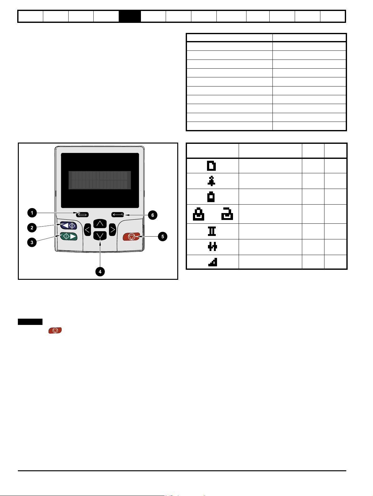
Safety
NOTE
information
Product
information
Mechanical
installation
Electrical
installation
Getting
started
Basic
parameters
Running the
5 Getting started
This chapter introduces the user interfaces, menu structure and security
levels of the drive.
5.1 Understanding the display
The keypad can only be mounted on the drive.
5.1.1 KI-Keypad
The KI-Keypad display consists of two rows of text. The upper row
shows the drive status or the menu and parameter number currently
being viewed. The lower row of the display line shows the parameter
value or the specific trip type. The last two characters on the first row
may display special indications. If more than one of these indications is
active then the indications are prioritized as shown in Table 5-2.
When the drive is powered up the lower row will show the power up
parameter defined by Parameter Displayed At Power-Up (11.022).
Figure 5-1 KI-Keypad
motor
Optimization
NV Media Card
Operation
Onboard
PLC
Advanced
parameters
Diagnostics
Table 5-1 Keypad display formats
Display formats Value
IP Address 127.000.000.000
MAC Address 01ABCDEF2345
Time 12:34:56
Date 31-12-11 or 12-31-11
Version number 01.02.02.00
Character ABCD
32 bit number with decimal point 21474836.47
16 bit binary number 0100001011100101
Text M600
Number 1.5 Hz
Table 5-2 Active action icon
Active action icon Description
Accessing non-volatile
media card
Alarm active 1 2
Row
(1=top)
11
UL
Information
Priority
in row
1. Escape button
2. Start reverse (Auxiliary button)
3. Start forward
4. Navigation keys (x4)
5. Stop / Reset (red) button
6. Enter button
The red stop button is also used to reset the drive.
The parameter value is correctly displayed in the lower row of the
keypad display, see table below.
or
Keypad real-time clock
battery low
Drive security active and
locked or unlocked
13
14
Motor map 2 active 2 1
User program running 3 1
Keypad reference active 4 1
5.2 Keypad operation
5.2.1 Control buttons
The keypad consists of:
• Navigation Keys - Used to navigate the parameter structure and
change parameter values.
• Enter / Mode button - Used to toggle between parameter edit and
view mode.
• Escape / Exit button - Used to exit from parameter edit or view
mode. In parameter edit mode, if parameter values are edited and
the exit button pressed the parameter value will be restored to the
value it had on entry to edit mode.
• Start forward button - Use to provide a 'Run' command if keypad
mode is selected.
• Start reverse button - Used to control the drive if keypad mode is
selected and the reverse button is activated. If Enable Auxiliary Key
(06.013) = 1, then the keypad reference is toggled between run
forward and run reverse each time the button is pressed. If Enable
Auxiliary Key (06.013) = 2, then the button functions as a run
reverse key.
• Stop / Reset button - Used to reset the drive. In keypad mode can be
used for 'Stop'.
30 Unidrive M600 Control User Guide
Issue Number: 2

Safety
To enter Edit Mode,
press key,
Status
Mode
Parameter
Mode
Edit Mode
(Character to be edited in lower line of display flashing)
Change parameter values
using keys.
When returning
to Parameter
Mode use the
keys to select
another parameter
to change, if
required
To enter Parameter
Mode, press key or
Temporary
Parameter
Mode
Timeout
Timeout
To return to Status Mode,
RO
parameter
R/W
parameter
To select parameter
Press
is displayed)
To return to Parameter Mode,
Press key to keep the newparameter value
Press key to ignore the newparameter value and return
the parameter to the pre-edited value
Press key
Timeout
or
Press key
(
NOTE
Go to parameter
information
Product
information
Mechanical
installation
Figure 5-2 Display modes
Electrical
installation
Getting
started
Basic
parameters
Running the
motor
Optimization
NV Media Card
Operation
Onboard
PLC
Advanced
parameters
Diagnostics
UL
Information
The navigation keys can only be used to move between menus if Pr 00.049 has been set to show 'All Menus'. Refer to section 5.9 Parameter access
level and security on page 36.
5.2.2 Quick access mode
The quick access mode allows direct access to any parameter without
scrolling through menus and parameters.
To enter the quick access mode, press and hold the Enter button
on the keypad while in ‘parameter mode’.
Figure 5-3 Quick access mode
5.2.3 Keypad shortcuts
In ‘parameter mode’:
• If the up and down keypad buttons are pressed
together, then the keypad display will jump to the start of the
parameter menu being viewed, i.e. Pr 05.005 being viewed, when
the above buttons pressed together will jump to Pr 05.000.
• If the left and right keypad buttons are pressed together,
then the keypad display will jump to the last viewed parameter in
Menu 0.
In ‘parameter edit mode’:
• If the up and down keypad buttons are pressed
together, then the parameter value of the parameter being edited will
be set to 0.
• If the left and right keypad buttons are pressed together, the
least significant digit (furthest right) will be selected on the keypad
display for editing.
Unidrive M600 Control User Guide 31
Issue Number: 2

Safety
12
34
WARNING
NOTE
NOTE
*
*
Menu 0
....MM.000....
00.050
00.049
00.048
00.047
00.046
00.001
00.002
00.003
00.004
00.005
Moves
between
parameters
Menu 41
Menu 1
Menu 2
Moves between Menus
41.029
41.028
41.027
41.026
41.025
41.001
41.002
41.003
41.004
41.005
01.001
01.002
01.003
01.004
01.005
01.050
01.049
01.048
01.047
01.046
Option module menus
(S.mm.ppp
)*
information
Product
information
Mechanical
installation
Electrical
installation
Getting
started
Basic
parameters
Running the
Figure 5-4 Mode examples
1. Parameter view mode: Read write or Read only
2. Status mode: Drive healthy status
If the drive is ok and the parameters are not being edited or viewed, the
upper row of the display will show one of the following:
• ‘Inhibit’, ‘Ready’ or ‘Run’.
3. Status mode: Trip status
When the drive is in trip condition, the upper row of the display will
indicate that the drive has tripped and the lower row of the display will
show the trip code. For further information regarding trip codes. refer to
Table 11-3 Trip indications on page 185.
4. Status mode: Alarm status
During an ‘alarm’ condition the upper row of the display flashes between
the drive status (Inhibit, Ready or Run, depending on what is displayed)
and the alarm.
motor
Optimization
NV Media Card
Operation
Onboard
PLC
Advanced
parameters
Diagnostics
5.3 Menu structure
The drive parameter structure consists of menus and parameters.
The drive initially powers up so that only Menu 0 can be viewed. The up
and down arrow buttons are used to navigate between parameters and
once Pr 00.049 has been set to 'All Menus' the left and right buttons are
used to navigate between menus. For further information, refer to
section 5.9 Parameter access level and security on page 36
Figure 5-5 Parameter navigation
* Can only be used to move between menus if all menus have
been enabled (Pr 00.049). Refer to section 5.9 Parameter
access level and security on page 36.
The menus and parameters roll over in both directions.
i.e. if the last parameter is displayed, a further press will cause the
display to rollover and show the first parameter.
When changing between menus the drive remembers which parameter
was last viewed in a particular menu and thus displays that parameter.
Figure 5-6 Menu structure
UL
Information
Do not change parameter values without careful
When changing the values of parameters, make a note of the new
values in case they need to be entered again.
For new parameter-values to apply after the line power supply to the
drive is interrupted, new values must be saved. Refer to section
5.7 Saving parameters on page 35.
consideration; incorrect values may cause damage or a
safety hazard.
* The option module menus (S.mm.ppp) are only displayed if option
modules are installed. Where S signifies the option module slot number
and the mm.ppp signifies the menu and the parameter number of the
option module's internal menus and parameter.
32 Unidrive M600 Control User Guide
Issue Number: 2

Safety
Menu 0
00.004
00.005
00.006
Menu 2
02.021
Menu 1
01.014
Menu 4
04.007
5
0
150
0
150
5
information
Product
information
Mechanical
installation
Electrical
installation
Getting
started
Basic
parameters
Running the
motor
Optimization
NV Media Card
Operation
Onboard
PLC
Advanced
parameters
Diagnostics
UL
Information
5.4 Menu 0
Menu 0 is used to bring together various commonly used parameters for
basic easy set up of the drive. The parameters displayed in Menu 0 can
be configured in Menu 22.
Appropriate parameters are copied from the advanced menus into Menu
0 and thus exist in both locations.
For further information, refer to Chapter 6 Basic parameters on page 38.
Figure 5-7 Menu 0 copying
5.5 Advanced menus
The advanced menus consist of groups or parameters appropriate to a
specific function or feature of the drive. Menus 0 to 41 can be viewed on
the KI-Keypad.
The option module menus (S.mm.ppp) are only displayed if option
modules are installed. Where S signifies the option module slot number
and the mm.ppp signifies the menu and parameter number of the option
module’s internal menus and parameter.
Table 5-3 Advanced menu descriptions
Menu Description
Commonly used basic set up parameters for quick / easy
0
programming
1 Frequency / Speed reference
2Ramps
3 Speed feedback and speed control
4 Torque and current control
5 Motor control
6 Sequencer and clock
7 Analog I/O, Temperature monitoring
8 Digital I/O
Programmable logic, motorized pot, binary sum, timers and
9
scope
10 Status and trips
11 Drive set-up and identification, serial communications
12 Threshold detectors and variable selectors
13 Standard motion control
14 User PID controller
15 Option module slot 1 set-up menu
16 Option module slot 2 set-up menu
17 Option module slot 3 set-up menu
18 General option module application menu 1
19 General option module application menu 2
20 General option module application menu 3
21 Second motor parameters
22 Menu 0 set-up
23 Not allocated
28 Reserved menu
29 Reserved menu
30 Onboard user programming application menu
Slot 1 Slot 1 option menus*
Slot 2 Slot 2 option menus*
Slot 3 Slot 3 option menus*
*Only displayed when the option modules are installed.
Unidrive M600 Control User Guide 33
Issue Number: 2

Safety
NOTE
information
Product
information
Mechanical
installation
Electrical
installation
Getting
started
Basic
parameters
Running the
5.5.1 KI-Keypad set-up menu
To enter the keypad set-up menu press and hold the escape
button on the keypad from status mode. All the keypad parameters are
saved to the keypad non-volatile memory when exiting from the keypad
set-up menu.
To exit from the keypad set-up menu press the escape or or
button. Below are the keypad set-up parameters.
Table 5-4 KI-Keypad set-up parameters
Parameters Range Type
Classic English (0)
English (1)
German (2)
Keypad.00 Language*
French (3)
RW
Italian (4)
Spanish (5)
Chinese (6)
Keypad.01 Show Units Off (0), On (1) RW
Keypad.02 Backlight Level 0 to 100 % RW
Keypad.03 Keypad Date
Keypad.04 Keypad Time
Keypad.05
Show Raw Text Parameter
Values
Keypad.06 Software Version
Keypad. 07 Language version
01.01.10 to
31.12.99
00:00:00 to
23:59:59
Off (0), On (1) RW
00.00.00.00 to
99.99.99.99
00.00.00.00 to
99.99.99.99
RO
RO
RO
RO
Keypad. 08 Font version 0 to 1000 RO
Keypad. 09 Show menu names Off or on RW
It is not possible to access the keypad parameters via any
communications channel.
* The languages available will depend on the keypad software version.
5.5.2 Display messages
The following tables indicate the various possible mnemonics which can
be displayed by the drive and their meaning.
motor
Optimization
NV Media Card
Operation
Onboard
PLC
Advanced
parameters
Diagnostics
Table 5-5 Status indications
Upper row
string
Description
The drive is inhibited and cannot be run.
The Safe Torque Off signal is not applied to
Inhibit
Safe Torque Off terminals or Pr 06.015 is
set to 0. The other conditions that can
prevent the drive from enabling are shown
as bits in Enable Conditions (06.010)
The drive is ready to run. The drive enable
Ready
is active, but the drive inverter is not active
because the final drive run is not active
Stop The drive is stopped / holding zero speed Enabled
Run The drive is active and running Enabled
Scan
The drive is enabled in Regen mode and is
trying to synchronize to the supply
Supply Loss Supply loss condition has been detected Enabled
The motor is being decelerated to zero
Deceleration
speed / frequency because the final drive
run has been deactivated
dc injection The drive is applying dc injection braking Enabled
Position
Positioning / position control is active
during an orientation stop
The drive has tripped and no longer
Trip
controlling the motor. The trip code
appears in the lower display
Active
Under
Vol tag e
The Regen unit is enabled and
synchronized to the supply
The drive is in the under voltage state
either in low voltage or high voltage mode
Heat The motor pre-heat function is active Enabled
Phasing
The drive is performing a ‘phasing test on
enable’
5.5.3 Alarm indications
An alarm is an indication given on the display by alternating the alarm
string with the drive status string on the upper row and showing the
alarm symbol in the last character in the upper row. Alarms strings are
not displayed when a parameter is being edited, but the user will still see
the alarm character on the upper row.
Table 5-6 Alarm indications
UL
Information
Drive
output
stage
Disabled
Disabled
Enabled
Enabled
Enabled
Disabled
Enabled
Disabled
Enabled
Alarm string Description
Brake resistor overload. Braking Resistor Thermal
Brake Resistor
Accumulator (10.039) in the drive has reached 75.0
% of the value at which the drive will trip.
Motor Protection Accumulator (04.019) in the drive
Motor Overload
has reached 75.0 % of the value at which the drive
will trip and the load on the drive is >100 %.
Regen inductor overload. Inductor Protection
Ind Overload
Accumulator (04.019) in the drive has reached
75.0 % of the value at which the drive will trip and
the load on the drive is >100 %.
Drive over temperature. Percentage Of Drive
Drive Overload
Thermal Trip Level (07.036) in the drive is greater
than 90 %.
Auto Tune
Limit Switch
The autotune procedure has been initialized and an
autotune in progress.
Limit switch active. Indicates that a limit switch is
active and that is causing the motor to be stopped.
34 Unidrive M600 Control User Guide
Issue Number: 2

Safety
Regen
NOTE
information
Product
information
Mechanical
installation
Electrical
installation
Getting
started
Basic
parameters
Table 5-7 Option module and NV media card and other status
indications at power-up
First row
string
Second row string Status
Booting Parameters Parameters are being loaded
Drive parameters are being loaded from a NV Media Card
Booting User Program User program being loaded
User program is being loaded from a NV Media Card to the drive
Booting
Option
Program
User program being loaded
User program is being loaded from a NV Media Card to the option
module in slot X
Writing To NV Card
Data being written to NV Media
Card
Data is being written to a NV Media Card to ensure that its copy of the
drive parameters is correct because the drive is in Auto or Boot mode
Waiting For Power System Waiting for power stage
The drive is waiting for the processor in the power stage to respond
after power-up
Waiting For Options Waiting for an option module
Running the
motor
Optimization
NV Media Card
Operation
Onboard
PLC
Advanced
parameters
Diagnostics
UL
Information
5.6 Changing the operating mode
Changing the operating mode returns all parameters to their default
value, including the motor parameters. User security status (00.049) and
User security code (00.034) are not affected by this procedure).
Procedure
Use the following procedure only if a different operating mode is
required:
1. Ensure the drive is not enabled, i.e. terminal 31 is open or Pr 06.015
is Off (0)
2. Enter either of the following values in Pr mm.000, as appropriate:
1253 (50Hz AC supply frequency)
1254 (60Hz AC supply frequency)
3. Change the setting of Pr 00.048 as follows:
Pr 00.048 setting Operating mode
1 Open-loop
2RFC-A
3RFC-S
The drive is waiting for the options modules to respond after power-up
Uploading
From
Options Loading parameter database
At power-up it may be necessary to update the parameter database
held by the drive because an option module has changed or because
an applications module has requested changes to the parameter
structure. This may involve data transfer between the drive an option
modules. During this period ‘Uploading From Options’ is displayed
4 Regen
The figures in the second column apply when serial communications are
used.
4. Either:
• Press the red reset button
• Toggle the reset digital input
• Carry out a drive reset through serial communications by setting
Pr 10.038 to 100.
Entering 1253 or 1254 in Pr mm.000 will only load defaults if the setting
of Pr 00.048 has been changed.
5.7 Saving parameters
When changing a parameter in Menu 0, the new value is saved when
pressing the Enter button to return to parameter view mode from
parameter edit mode.
If parameters have been changed in the advanced menus, then the
change will not be saved automatically. A save function must be carried
out.
Procedure
1. Select ‘Save Parameters'* in Pr mm.000 (alternatively enter a value
of 1001 in Pr mm.000)
2. Either:
• Press the red reset button
• Toggle the reset digital input, or
• Carry out a drive reset through serial communications by setting
Pr 10.038 to 100
Unidrive M600 Control User Guide 35
Issue Number: 2

Safety
information
Product
information
Mechanical
installation
Electrical
installation
Getting
started
Basic
parameters
Running the
motor
Optimization
NV Media Card
Operation
Onboard
PLC
Advanced
parameters
Diagnostics
UL
Information
5.8 Restoring parameter defaults
Restoring parameter defaults by this method saves the default values in
the drives memory. User security status (00.049) and User security code
(00.034) are not affected by this procedure).
Procedure
1. Ensure the drive is not enabled, i.e. terminal 31 is open or Pr 06.015
is Off (0)
2. Select 'Reset 50 Hz Defs' or 'Reset 60 Hz Defs' in Pr mm.000.
(alternatively, enter 1233 (50 Hz settings) or 1244 (60 Hz settings) in
Pr mm.000).
3. Either:
• Press the red reset button
• Toggle the reset digital input
• Carry out a drive reset through serial communications by setting
Pr 10.038 to 100
5.9 Parameter access level and security
The parameter access level determines whether the user has access to
Menu 0 only or to all the advanced menus (Menus 1 to 41) in addition to
Menu 0.
The User Security determines whether the access to the user is read
only or read write.
Both the User Security and Parameter Access Level can operate
independently of each other as shown in Table 5-8.
Table 5-8 Parameter access level and security
User
security
status
Access level
(00.049)
0 Menu 0 None RW Not visible
1 All Menus None RW RW
Read-only
2
Menu 0
3 Read-only
4 Status only
5 No access
The default settings of the drive are Parameter Access Level Menu 0
and user Security Open i.e. read / write access to Menu 0 with the
advanced menus not visible.
User
security
(00.034)
Menu 0
status
Advanced
menu status
Open RW Not visible
Closed RO Not visible
Open RW RW
Closed RO RO
Open RW RW
Closed Not visible Not visible
Open RW RW
Closed Not visible Not visible
5.9.1 User Security Level / Access Level
The drive provides a number of different levels of security that can be set
by the user via User Security Status (00.049); these are shown in the
table below.
User Security
Status
Description
(Pr 00.049)
Menu 0 (0)
All menus (1)
Read- only
Menu 0 (2)
Read-only (3)
Status only (4)
All writable parameters are available to be edited
but only parameters in Menu 0 are visible
All parameters are visible and all writable
parameters are available to be edited
Access is limited to Menu 0 parameters only. All
parameters are read-only
All parameters are read-only however all menus
and parameters are visible
The keypad remains in status mode and no
parameters can be viewed or edited
The keypad remains in status mode and no
No access (5)
parameters can be viewed or edited. Drive
parameters cannot be accessed via a comms/
fieldbus interface in the drive or any option module
5.9.2 Changing the User Security Level /Access Level
The security level is determined by the setting of Pr 00.049 or Pr 11.044.
The Security Level can be changed through the keypad even if the User
Security Code has been set.
5.9.3 User Security Code
The User Security Code, when set, prevents write access to any of the
parameters in any menu.
Setting User Security Code
Enter a value between 1 and 2147483647 in Pr 00.034 and press the
button; the security code has now been set to this value. In order
to activate the security, the Security level must be set to desired level in
Pr 00.049. When the drive is reset, the security code will have been
activated and the drive returns to Menu 0 and the symbol is
displayed in the right hand corner of the keypad display. The value of
Pr 00.034 will return to 0 in order to hide the security code.
Unlocking User Security Code
Select a parameter that need to be edited and press the button,
the upper display will now show ‘Security Code’. Use the arrow buttons
to set the security code and press the button. With the correct
security code entered, the display will revert to the parameter selected in
edit mode.
If an incorrect security code is entered, the following message ‘Incorrect
security code’ is displayed, then the display will revert to parameter view
mode.
Disabling User Security
Unlock the previously set security code as detailed above. Set Pr 00.034
to 0 and press the button. The User Security has now been
disabled, and will not have to be unlocked each time the drive is
powered up to allow read / write access to the parameters.
36 Unidrive M600 Control User Guide
Issue Number: 2

Safety
NOTE
NOTE
information
Product
information
Mechanical
installation
Electrical
installation
Getting
started
Basic
parameters
Running the
motor
Optimization
NV Media Card
Operation
Onboard
PLC
Advanced
parameters
Diagnostics
UL
Information
5.10 Displaying parameters with nondefault values only
By selecting 'Show non-default' in Pr mm.000 (Alternatively, enter 12000
in Pr mm.000), the only parameters that will be visible to the user will be
those containing a non-default value. This function does not require a
drive reset to become active. In order to deactivate this function, return
to Pr mm.000 and select 'No action' (alternatively enter a value of 0).
Please note that this function can be affected by the access level
enabled, refer to section 5.9 Parameter access level and security on
page 36 for further information regarding access level.
5.11 Displaying destination parameters only
By selecting 'Destinations' in Pr mm.000 (Alternatively enter 12001 in
Pr mm.000), the only parameters that will be visible to the user will be
destination parameters. This function does not require a drive reset to
become active. In order to deactivate this function, return to Pr mm.000
and select 'No action' (alternatively enter a value of 0).
Please note that this function can be affected by the access level
enabled, refer to section 5.9 Parameter access level and security on
page 36 for further information regarding access level.
5.12 Communications
The Unidrive M600 drive offers a 2 wire EIA 485 interface. This enables
the drive set-up, operation and monitoring to be carried out with a PC or
controller if required.
5.12.1 EIA 485 Serial communications
The EIA 485 interface provides two parallel RJ45 connectors allowing
easy daisy chaining. The drive only supports Modbus RTU protocol.
The serial communications port of the drive is a RJ45 socket, which is
isolated from the power stage and the other control terminals (see
section 4.2 Communication connections on page 22 for connection and
isolation details).
The communications port applies a 2 unit load to the communications
network.
USB/EIA 232 to EIA 485 Communications
An external USB/EIA 232 hardware interface such as a PC cannot be
used directly with the 2-wire EIA 485 interface of the drive. Therefore a
suitable converter is required.
Suitable USB to EIA 485 and EIA 232 to EIA 485 isolated converters are
available from Control Techniques as follows:
• CT USB Comms cable (CT Part No. 4500-0096)
• CT EIA 232 Comms cable (CT Part No. 4500-0087)
When using the CT EIA 232 Comms cable the available baud rate is
limited to 19.2 k baud.
When using one of the above converters or any other suitable converter
with the drive, it is recommended that no terminating resistors be
connected on the network. It may be necessary to 'link out' the
terminating resistor within the converter depending on which type is
used. The information on how to link out the terminating resistor will
normally be contained in the user information supplied with the
converter.
Serial communications set-up parameters
The following parameters need to be set according to the system
requirements.
Serial communications set-up parameters
8 2 NP (0),
8 1 NP (1),
8 1 EP (2),
8 1 OP (3),
8 2 NP M (4),
8 1 NP M (5),
8 1 EP M (6),
Serial Mode
(00.035)
8 1 OP M (7),
7 2 NP (8),
7 1 NP (9),
7 1 EP (10),
7 1 OP (11),
7 2 NP M (12),
7 1 NP M (13),
7 1 EP M (14),
7 1 OP M (15)
300 (0),
600 (1),
1200 (2),
2400 (3),
Serial Baud Rate
(00.036)
4800 (4),
9600 (5),
19200 (6),
38400 (7),
57600(8),
76800(9),
115200 (10)
Serial Address
(00.037)
1 to 247
Reset Serial
Communications
0 to 1
(00.052)
Please refer to section 7.7 CT Modbus RTU specification on page 92 for
further details on the CT Modbus RTU specification.
The drive only supports the
Modbus RTU protocol and is
always a slave. This parameter
defines the supported data
formats used by the EIA 485
comms port (if installed) on the
drive. This parameter can be
changed via the drive keypad,
via a option module or via the
comms interface itself.
This parameter can be
changed via the drive keypad,
via a option module or via the
comms interface itself. If it is
changed via the comms
interface, the response to the
command uses the original
baud rate. The master should
wait at least 20 ms before
sending a new message using
the new baud rate.
This parameter defines the
serial address and an
addresses between 1 and 247
are permitted.
When the above parameters
are modified the changes do
not have an immediate effect
on the serial communication
system. The new values are
used after the next power up or
if Reset Serial Communications
is set to 1.
Unidrive M600 Control User Guide 37
Issue Number: 2

Safety
information
Product
information
Mechanical
installation
Electrical
installation
Getting
started
Basic
parameters
Running the
motor
Optimization
NV Media Card
Operation
Onboard
PLC
Advanced
parameters
Diagnostics
UL
Information
6 Basic parameters
Menu 0 is used to bring together various commonly used parameters for basic easy set up of the drive. All the parameters in Menu 0 appear in other
menus in the drive (denoted by {…}). Menu 22 can be used to configure the parameters in Menu 0.
Parameter ranges and Variable minimum/maximums:
Some parameters in the drive have a variable range with a variable minimum and a variable maximum value which is dependent on one of the
following:
• The settings of other parameters
• The drive rating
• The drive mode
• Combination of any of the above
For more information please see section 10.1 Parameter ranges and Variable minimum/maximums: on page 109.
38 Unidrive M600 Control User Guide
Issue Number: 2

Safety
information
Product
information
Mechanical
installation
Electrical
installation
Getting
started
6.1 Menu 0: Basic parameters
Basic
parameters
Running the
motor
Optimization
NV Media Card
Operation
Onboard
PLC
Advanced
parameters
Diagnostics
UL
Information
Parameter
00.001 Minim um Reference Clamp {01.007} VM_NEGATIVE_REF_CLAMP1 Hz / rpm 0 Hz / rpm RW Num US
00.002 Maximum Reference Clamp1 {01.006} VM_POSITIVE_REF_CLAMP1 Hz / rpm
00.003 Acceleration Rate 1 {02.011}
00.004 Deceleration Rate 1 {02.021}
00.005 Reference Selector {01.014}
00.006 Symmetrical Current Limit {04.007} 0.0 to VM_MOTOR1_CURRENT_LIMIT % 165.0 %* 175.0 %** RW Num RA US
Open-loop Control Mode / Action On
Enable
00.007
Speed Controller Proportional Gain
Kp1
Low Frequency Voltage Boost {05.015} 0.0 to 25.0 % 3.0 % RW Num US
00.008
Speed Controller Integral Gain Ki1 {03.011}
Dynamic V to F Select {05.013} Off (0) or On (1) Off (0) RW Bit US
00.009
Speed Controller Differential
Feedback Gain Kd 1
Motor Rpm {05.004} ±180000 rpm RO Num ND NC PT FI
00.010
Speed Feedback {03.002} VM_SPEED rpm RO Num ND NC PT FI
00.011 Output Frequency {05.001}
00.012 Current Magnitude {04.001} 0.000 to VM_DRIVE_CURRENT_UNIPOLAR A RO Bit ND NC PT FI
00.013 Torque Producing Current {04.002} VM_DRIVE_CURRENT A RO Bit ND NC PT FI
00.014 Torque Mode Selector {04.011} 0 or 1 0 to 5 0 RW Num US
00.015 Ramp Mode {02.004}
00.016 Ramp Enable {02.002} Off (0) or On (1) On (1) RW Bit US
Digital Input 6 Destination {08.026} 0.000 to 59.999 06.031 RW Nu m DE PT US
00.017
Current Reference Filter 1 Time
Constant
00.019 Analog Input 2 Mode {07.011}
00.020 Analog Input 2 Destination {07.014} 00.000 to 59.999 01.037 RW Num DE PT US
00.021 Analog Input 3 Mode {07.015}
00.022 Bipolar Reference Enable {01.010} Off (0) or On (1) Off (0) RW Bit US
00.023 Jog Reference {01.005} 0.0 to 400.0 Hz
00.024 Preset Reference 1 {01.021} VM_SPEED_FREQ_REF Hz / rpm 0.0 Hz / rpm RW Num US
00.025 Preset Reference 2 {01.022} VM_SPEED_FREQ_REF Hz / rpm 0.0 Hz / rpm RW Num US
Preset Reference 3 {01.023}
00.026
Overspeed Threshold {03.008} 0 to 40000 rpm 0 rpm RW Num US
00.027 Preset Reference 4 {01.024}
00.028 Enable Auxiliary Key {06.013} Disabled (0), Forward / Reverse (1), Reverse (2) Disabled (0) RW Txt US
NV Media Card File Previously
00.029
Loaded
00.030 Parameter Cloning {11.042} None (0), Read (1), Program (2), Auto (3), Boot (4) None (0) RW Txt NC US
00.031 Rated Voltage {11.033} 200 V (0), 400 V (1), 575 V (2), 690 V (3) RO Txt ND NC PT
00.032 Maximum Heavy Duty Rating {11.032} 0.000 to 99999.999 A RO Num ND NC PT
{05.014}
{03.010} 0.0000 to 200.000 s/rad 0.0100 s/rad RW Num US
{03.012} 0.00000 to 0.65535 1/rad 0.00000 1/rad RW Num US
{04.012} 0.0 to 25.0 ms 1.0 ms 2.0 ms RW Num US
{11.036} 0 to 999 0 RO Num NC PT
OL RFC-A RFC-S OL RFC-A RFC-S
0.0 to
VM_ACCEL_RATE
s/100 Hz
0.0 to
VM_ACCEL_RATE
s/100 Hz
A1 A2 (0), A1 Preset (1), A2 Preset (2)
Preset (3), Keypad (4), Precision (5)
Ur S (0), Ur (1),
Fixed (2),
Ur Auto (3), Ur I (4),
Square (5)
VM_SPEED_FREQ
_REF Hz
Fast (0),
Standard (1),
Std boost (2)
4-20 mA Low (-4), 20-4 mA Low (-3),
4-20 mA Hold (-2), 20-4 mA Hold (-1), 0-2 0 mA (0),
20-0 mA (1), 4-20 mA Trip (2), 20-4 mA Trip (3),
4-20 mA (4), 20-4 mA (5), Volt (6)
Thermistor (8), Therm No Trip (9)
VM_SPEED_
FREQ_REF Hz
VM_SPEED_FREQ
_REF Hz
Range Default
50 Hz default:
50.0 Hz
60 Hz default:
60.0 Hz
0.000 to VM_ACCEL_RATE
s/1000 rpm
0.000 to VM_ACCEL_RATE
s/1000 rpm
Keypad Ref (6)
0.00 to 655.35 s2/rad 0.05 s2/rad
±2000.0 Hz RO Num ND NC PT FI
Fast (0), Standard (1) Standard (1) RW Txt US
Volt (6), Therm Short Cct (7),
0.0 to 4000.0 rpm
5.0 s/100 Hz 2.000 s/1000 rpm RW Num US
10.0 s/100 Hz 2.000 s/1000 rpm RW Num US
Typ e
50 Hz default: 1500.0 rpm
60 Hz default: 1800.0 rpm
A1 A2 (0) RW Txt US
Ur I (4) RW Txt US
Volt (6) RW Txt US
Volt (6) RW Txt US
0.0 Hz / rpm RW Num US
0.0 Hz RW Num US
0.0 Hz RW Num US
RW N um US
RW N um US
Unidri ve M600 Control User Guide 39
Issue Number: 2

Safety
information
Product
information
Mechanical
installation
Electrical
installation
Getting
started
Basic
parameters
Running the
motor
Optimization
NV Media Card
Operation
Onboard
PLC
Advanced
parameters
Diagnostics
UL
Information
Parameter
Catch A Spinning Motor {06.009}
00.033
Rated Speed Optimization Select {05.016}
00.034 User Security Code {11.030} 0 to 2147483647 0 RW Num ND NC PT US
00.035 Seri al Mode {11.024}
00.036 Serial Baud Rate {11.025}
00.037 Serial Address {11.023} 1 to 247 1 RW Num US
00.038 Current Controller Kp Gain {04.013} 0 to 30000 20 150 RW Num US
00.039 Current Controller Ki Gain {04.014} 0 to 30000 40 2000 RW Num US
00.040 Auto-tune {05.012} 0 to 2 0 to 5 0 to 6 0 RW Num NC
00.041 Maximum Switching Frequency {05.018}
00.042 Number Of Motor Poles {05.011} Automatic (0) to 480 Poles (240) Automatic (0) 8 Poles (4) RW Num US
00.043 Rated Power Factor*** {05.010} 0.000 to 1.000 0.850 RW Num RA US
00.044 Rated Voltage {05.009} 0 to VM_AC_VOLTAGE_SET V
00.045 Rate d Speed {05.008}
00.046 Rated Current {05.007} 0.000 to VM_RATED_CURRENT A
Rated Frequency {05.006} 0.0 to 550.0 Hz
00.047
Volts per 1000 rpm {05.033}
00.048 User Drive Mode {11.031} Open-loop (1), RFC-A (2), RFC-S (3), Regen (4) Open-loop (1) RFC-A (2) RFC-S (3) RW Txt ND NC PT
00.049 User Security Status {11.044}
00.050 Software Version {11.029} 0 to 99999999 RO Num ND NC PT
00.051 Action On Trip Detection {10.037} 00000 to 11111 00000 RW Bin US
00.052 Reset Serial Communications {11.020} Off (0) or On (1) Off (0) RW Bit ND NC
Motor Thermal Time
00.053
Constant 1
00.054 RFC Low Speed Mode {05.064}
Low Speed Sensorless
00.055
Mode Current
00.056 No-load Lq {05.072}
Iq Test Current For
00.057
Inductance Measurement
Phase Offset At Iq Test
00.058
Current
Lq At The Defined Iq Test
00.059
Current
Id Test Current for
00.060
Inductance Measurement
Lq At The Defined Id Test
00.061
Current
* For size 9 and above the default is 141.9 %
** For size 9 and above the default is 150.0 %
*** Following a rotating autotune Pr 00.043 {05.010} is continuously written by the drive, calculated from the value of Stator Inductance (Pr 05.025). To manually enter a value into Pr 00.043 {05.010},
Pr 05.025 will need to be set to 0. Please refer to the description of Pr 05.010 in the Parameter Reference Guide for further details
{04.015} 1.0 to 3000.0 s 89.0 s RW Num US
{05.071}
{05.075} 0to200% 100 % RW Num US
{05.077} ±90.0 ° 0.0 ° RW Num RA US
{05.078}
{05.082} -100 to 0 % -50 % RW Num US
{05.084}
OL RFC-A RFC-S OL RFC-A RFC-S
Disable (0),
Enable (1),
Fwd Only (2),
Rev Only (3)
8 2 NP (0), 8 1 NP (1), 8 1 EP (2), 8 1 OP (3),
8 2 NP M (4), 8 1 NP M (5), 8 1 EP M (6),
8 1 OP M (7), 7 2 NP (8), 7 1 NP (9), 7 1 EP (10),
7 1 OP (11), 7 2 NP M (12), 7 1 NP M (13),
300 (0), 600 (1), 1200 (2), 2400 (3), 4800 (4),
9600 (5), 19200 (6), 38400 (7), 57600 (8),
2 (0) kHz, 3 (1) kHz, 4 (2) kHz, 6 (3) kHz, 8 (4) kHz,
0 to
33000 rpm
Menu 0 (0), All Menus (1), Read-only Menu 0 (2),
Read-only (3), Status Only (4), No Access (5)
Range Default
Disable (0) RW Txt US
Disabled (0),
Classic slow (1),
Classic fast (2),
Combined (3),
VARs only (4),
Voltage only (5)
7 1 EP M (14), 7 1 OP M (15)
76800 (9), 115200 (10)
12 (5) kHz, 16 (6) kHz
0.00 to
33000.00
rpm
0.00 to
33000.00
rpm
0 to 10000 V
/ 1000 rpm
Injection (0),
Non-
salient (1)
Current (2),
Current No
Test (3)
0.0 to
1000.0 %
0.000 to
500.000 mH
0.000 to
500.000 mH
0.000 to
500.000 mH
Eur - 1500
USA - 1800
Maximum Heavy Duty Rating (Pr 00.032
Disabled (0) RW Txt U S
8 2 NP (0) RW Txt US
19200 (6) RW Txt US
3 (1) kHz RW Txt RA US
200V drive: 230V
50Hz default 400V drive: 400V
60Hz default 400V drive: 460V
575V drive: 575V
690V drive: 690V
rpm
rpm
50Hz: 50.0
60Hz: 60.0
Eur -
1450.00 rpm
USA -
1750.00 rpm
{11.032}) A
Menu 0 (0) RW Txt ND PT
3000.00
1000 rpm
salient (1)
0.000 mH RW Num RA US
0.000 mH RW Num RA US
0.000 mH RW Num RA US
RW Num RA U S
RW Num US
rpm
RW Num RA U S
RW Num US
98 V /
RW Num US
Non-
RW Txt US
20.0 % RW Num RA US
Typ e
RW Read / Write RO Read only Num Number parameter Bit Bit parameter Txt Text string Bin Binary parameter FI Filtered
ND No default value NC Not copied PT Protected parameter RA Rating dependent US User save PS Power-down save DE Destination
40 Unidrive M600 Control User Guide
Issue Number: 2

Safety
information
Product
information
Mechanical
installation
Electrical
installation
Getting
started
Basic
parameters
Running the
motor
Optimization
NV Media Card
Operation
Onboard
PLC
Advanced
parameters
Diagnostics
UL
Information
Unidri ve M600 Control User Guide 41
Issue Number: 2

Safety
00.XXX
00.XXX
Key
Read-write
(RW)
parameter
Read-only
(RO)
parameter
Input
terminals
Output
terminals
X
X
X
X
The parameters are all shown in their default settings
Analog
Input
2 Mode
00.019
5
6
7
Analog reference
Keypad reference
00.024
00.025
00.026
00.027
Preset
Reference 1
Preset
Reference 2
Preset
Reference 3
Preset
Reference 4
Preset frequency
reference
Analog
Reference 2
00.020
??.??
Any
unprotected
variable
parameter
??.??
01.037
Analog
Input 2
Destination
28
29
0
1
2
3
4
5
Precision reference
Open Loop only
00.022
Bipolar
Reference
Enable
00.028
Enable Auxiliary Key
00.023
Jog Reference
A1.A2
A1.Preset
A2.Preset
Preset
Keypad
Precision
6
01.015
Pr
set
01.050
>1
Keypad Ref
01.050
00.005
Reference
Selector
information
Product
information
Mechanical
installation
Figure 6-1 Menu 0 logic diagram
Electrical
installation
Getting
started
Basic
parameters
Running the
motor
Optimization
NV Media Card
Operation
Onboard
PLC
Advanced
parameters
Diagnostics
UL
Information
42 Unidrive M600 Control User Guide
Issue Number: 2

Safety
OL> FREQUENCY
SPEED
TORQUE
Motor
control
Speed
Controller
Proportional
Gain KP1
OL> Catch A
Spinning Motor
RFC-A
> Rated Speed
Optimisation Select
Speed
Feedback
00.033
00.006
00.007
00.008
00.009
RFC-A,
RFC-S>
Speed-loop
PID
gains
9 10 24
AT ZERO SPEED
Current
Limit
Number Of Motor Poles
Rated Power Factor
RatedVoltage
Rated Speed
Rated Current
Rated Frequency
00.042 ~ 00.047
Motor
parameters
Power stage
00.007
00.008
00.009
OL>
Motor-voltage control
Estimated
Motor rpm
_
+
L1 L2 L3
_
+
U V W
Resistor
optional
Drive
RUN
FORWARD
RUN
REVERSE
RESET
Maximum
Reference
Clamp
00.001
00.002
26 27
25
Ramps
Acceleration
Rate 1
Deceleration
Rate 1
RampMode
00.003
00.004
00.015
RFC-A, RFC-S modes only
00.016
Ramp
Enable
Analog outputs Digital output
00.041
00.011
Maximum Switching
Frequency
Output Frequency
00.014
Tor que Mode
Selector
00.017
Current Reference
Filter
1 Time
Constant
RFC-A,
RFC-S>
RFC-A
RFC-S
Tor que
Producing
Sensorless
position
estimator
Current
Current
Magnitude
Magnetising
Current
+ BR
_
RFC-A,
RFC-S
RFC-A, RFC-S>
00.010
00.010
00.013
00.012
Minimum
Reference
Clamp
Speed
Controller
Integral
Gain KI1
Speed Controller
Differential
Feedback
Gain Kd1
Open Loop
Control Mode
Low Frequency
Voltage Boost
Dynamic V to F
Select
information
Product
information
Mechanical
installation
Electrical
installation
Getting
started
Basic
parameters
Running the
motor
Optimization
NV Media Card
Operation
Onboard
PLC
Advanced
parameters
Diagnostics
UL
Information
Unidri ve M600 Control User Guide 43
Issue Number: 2

Safety
information
Product
information
Mechanical
installation
Electrical
installation
Getting
started
Basic
parameters
Running the
motor
Optimization
NV Media Card
Operation
Onboard
PLC
Advanced
parameters
Diagnostics
UL
Information
6.2 Parameter descriptions
6.2.1 Pr mm.000
Pr mm.000 is available in all menus, commonly used functions are provided as text strings in Pr mm.000 shown in Table 6-1. The functions in Table
6-1 can also be selected by entering the appropriate numeric values (as shown in Table 6-2) in Pr mm.000. For example, enter 4001 in Pr mm.000 to
store drive parameters on an NV media card.
Table 6-1 Commonly used functions in xx.000
Value Equivalent value String Action
00
[No Action]
1001 1 [Save parameters] Save parameter under all conditions
6001 2
4001 3
6002 4
4002 5
6003 6
4003 7
12000 8
12001 9
1233 10
1244 11
1070 12
11001 13
[Load file 1] Load the drive parameters or user program file from NV media card file 001
[Save to file 1] Transfer the drive parameters to parameter file 001
[Load file 2] Load the drive parameters or user program file from NV media card file 002
[Save to file 2] Transfer the drive parameters to parameter file 002
[Load file 3] Load the drive parameters or user program file from NV media card file 003
[Save to file 3] Transfer the drive parameters to parameter file 003
[Show non-default] Displays parameters that are different from defaults
[Destinations] Displays parameters that are set
[Reset 50Hz Defs] Load parameters with standard (50 Hz) defaults
[Reset 60Hz Defs] Load parameters with US (60 Hz) defaults
[Reset modules] Reset all option modules
[Read Enc. NP P1]
No function
11051 14
[Read Enc. NP P2]
44 Unidrive M600 Control User Guide
Issue Number: 2

Safety
information
Product
information
Mechanical
installation
Electrical
installation
Getting
started
Basic
parameters
Running the
motor
Optimization
NV Media Card
Operation
Onboard
PLC
Advanced
parameters
Diagnostics
UL
Information
Table 6-2 Functions in Pr mm.000
Value Action
1000
Save parameters when Under Voltage Active (Pr 10.016) is not active and Low Under Voltage Threshold Select mode (Pr 06.067 = Off)
is not active.
1001 Save parameter under all conditions
1070 Reset all option modules
1233 Load standard (50 Hz) defaults
1234 Load standard (50 Hz) defaults to all menus except option module menus (i.e 15 to 20 and 24 to 28)
1244 Load US (60 Hz) defaults
1245 Load US (60 Hz) defaults to all menus except option module menus (i.e 15 to 20 and 24 to 28)
1253 Change drive mode and load standard (50 Hz) defaults
1254 Change drive mode and load US (60 Hz) defaults
1255 Change drive mode and load standard (50 Hz) defaults except for menus 15 to 20 and 24 to 28
1256 Change drive mode and load US (60 Hz) defaults except for menus 15 to 20 and 24 to 28
1299 Reset {Stored HF} trip.
2001* Create a boot file on a non-volatile media card based on the present drive parameters including all Menu 20 parameters
4yyy* NV media card: Transfer the drive parameters to parameter file xxx
5yyy* NV media card: Transfer the onboard user program to onboard user program file xxx
6yyy* NV media card: Load the drive parameters from parameter file xxx or the onboard user program from onboard user program file xxx
7yyy* NV media card: Erase file xxx
8yyy* NV Media card: Compare the data in the drive with file xxx
9555* NV media card: Clear the warning suppression flag
9666* NV media card: Set the warning suppression flag
9777* NV media card: Clear the read-only flag
9888* NV media card: Set the read-only flag
9999* NV media card: Erase and format the NV media card
59999 Delete onboard user program
12000** Only display parameters that are different from their default value. This action does not require a drive reset.
12001** Only display parameters that are used to set-up destinations (i.e. DE format bit is 1). This action does not require a drive reset.
40yyy Back-up all drive data.
60yyy Load all drive data.
* See Chapter 8 NV Media Card Operation on page 99 for more information on these functions.
** These functions do not require a drive reset to become active. All other functions require a drive reset to initiate the function.
To allow easy access to some commonly used functions, refer to the table overleaf. Equivalent values and strings are also provided in the table
above.
Unidri ve M600 Control User Guide 45
Issue Number: 2

Safety
information
Product
information
Mechanical
installation
Electrical
installation
Getting
started
Basic
parameters
6.3 Full descriptions
Table 6-3 Key to parameter table coding
Coding Attribute
RW Read/Write: can be written by the user
RO Read only: can only be read by the user
Bit 1 bit parameter. ‘On’ or ‘Off’ on the display
Num Number: can be uni-polar or bi-polar
Txt Text: the parameter uses text strings instead of numbers.
Bin Binary parameter
IP IP Address parameter
Mac Mac Address parameter
Date Date parameter
Time Time parameter
Chr Character parameter
Filtered: some parameters which can have rapidly changing
FI
values are filtered when displayed on the drive keypad for
easy viewing.
Destination: This parameter selects the destination of an
DE
input or logic function.
Rating dependent: this parameter is likely to have different
values and ranges with drives of different voltage and
current ratings. Parameters with this attribute will be
transferred to the destination drive by non-volatile storage
media when the rating of the destination drive is different
RA
from the source drive and the file is a parameter file.
However, the values will be transferred if only the current
rating is different and the file is a difference from default
type file.
No default: The parameter is not modified when defaults are
ND
loaded
Not copied: not transferred to or from non-volatile media
NC
during copying.
PT Protected: cannot be used as a destination.
User save: parameter saved in drive EEPROM when the
US
user initiates a parameter save.
Power-down save: parameter automatically saved in drive
PS
EEPROM when the under volts (UV) state occurs.
6.3.1 Parameter x.00
00.000
{mm.000}
RW Num ND NC PT
Ú
Parameter zero
0 to 65,535
Ö
Running the
motor
Optimization
RFC-A / RFC-S
Set Pr 00.001 at the required minimum motor speed for both directions
of rotation. The drive speed reference is scaled between Pr 00.001 and
Pr 00.002.
00.002 {01.006} Maximum Reference Clamp
RW Num US
OL
RFC-A
RFC-S
(The drive has additional over-speed protection).
Open-loop
Set Pr 00.002 at the required maximum output frequency for both
directions of rotation. The drive speed reference is scaled between
Pr 00.001 and Pr 00.002. [00.002] is a nominal value; slip compensation
may cause the actual frequency to be higher.
RFC-A / RFC-S
Set Pr 00.002 at the required maximum motor speed for both directions
of rotation. The drive speed reference is scaled between Pr 00.001 and
Pr 00.002.
For operating at high speeds see section 7.6 High speed operation on
page 90.
NV Media Card
Operation
VM_POSITIVE_REF_
Ú
CLAMP1 Hz / rpm
Onboard
PLC
Advanced
parameters
Ö
Diagnostics
50Hz default: 50.0 Hz
60Hz default: 60.0 Hz
50Hz default:1500.0 rpm
60Hz default:1800.0 rpm
6.3.3 Ramps, speed reference selection, current limit
00.003 {02.011} Acceleration Rate 1
RW Num US
OL
RFC-A
RFC-S
Set Pr 00.003 at the required rate of acceleration.
Note that larger values produce lower acceleration. The rate applies in
both directions of rotation.
00.004 {02.021} Deceleration Rate 1
RW Num US
OL
RFC-A
RFC-S
0.0 to VM_ACCEL_RATE
Ú
0.0 to VM_ACCEL_RATE
Ú
0.000 to
VM_ACCEL_RATE
0.000 to
VM_ACCEL_RATE
Ö
Ö
5.0 s/100 Hz
2.000 s/1000 rpm
10.0 s/100 Hz
2.000 s/1000 rpm
UL
Information
6.3.2 Speed limits
00.001 {01.007} Minimum Reference Clamp
RW Num US
OL
RFC-A
RFC-S
(When the drive is jogging, [00.001] has no effect.)
Open-loop
Set Pr 00.001 at the required minimum output frequency of the drive for
both directions of rotation. The drive speed reference is scaled between
Pr 00.001 and Pr 00.002. [00.001] is a nominal value; slip compensation
may cause the actual frequency to be higher.
VM_NEGATIVE_REF_
Ú
CLAMP1 Hz / rpm
Ö
0.0 Hz
0.0 rpm
Set Pr 00.004 at the required rate of deceleration.
Note that larger values produce lower deceleration. The rate applies in
both directions of rotation.
46 Unidrive M600 Control User Guide
Issue Number: 2

Safety
00.006[]
T
R
T
RATED
--------------------
100×=
00.006[]
I
R
I
RATED
-------------------
100×=
information
Product
information
Mechanical
installation
Electrical
installation
Getting
started
Basic
parameters
Running the
motor
Optimization
NV Media Card
Operation
Onboard
PLC
Advanced
parameters
Diagnostics
UL
Information
00.005 {01.014} Reference Selector
RW Txt US
OL
RFC-A
RFC-S
A1 A2 (0),
A1 Preset (1),
A2 Preset (2),
Ú
Preset (3), Keypad (4),
Precision (5),
Ö
A1 A2 (0)
Keypad Ref (6)
Use Pr 00.005 to select the required frequency/speed reference as
follows:
Setting Description
A1 A2 0
Analog input 1 OR analog input 2 selectable by
digital input, terminal 28
A1 Preset 1 Analog input 1 OR preset frequency/speed
A2 Preset 2 Analog input 2 OR preset frequency/speed
Preset 3 Pre-set frequency/speed
Keypad 4 Keypad mode
Precision 5 Precision reference
Keypad Ref 6 Keypad Reference
00.006 {04.007} Symmetrical Current Limit
RW Num US
OL
RFC-A
RFC-S
0.0 to VM_MOTOR1_
Ú
CURRENT_LIMIT %
Ö
165 %
175 %
Pr 00.006 limits the maximum output current of the drive (and hence
maximum motor torque) to protect the drive and motor from overload.
Set Pr 00.006 at the required maximum torque as a percentage of the
rated torque of the motor, as follows:
(%)
Where:
Required maximum torque
T
R
Motor rated torque
T
RATED
Alternatively, set Pr 00.006 at the required maximum active (torque-
producing) current as a percentage of the rated active current of the
motor, as follows:
6.3.4 Voltage boost, (open-loop), Speed-loop PID gains (RFC-A / RFC-S)
00.007 {05.014} Open-loop Control Mode (OL)
00.007 {03.010} Speed Controller Proportional Gain Kp1 (RFC)
RW
Txt /
Num
Ur S (0), Ur (1),
OL
Fixed (2), Ur Auto (3),
Ú
Ö
Ur I (4), Square (5)
RFC-A
RFC-S
0.0000 to 200.000 s/rad
Ú
Ö
0.0100 s/rad
Open-loop
There are six voltage modes available, which fall into two categories,
vector control and fixed boost. For further details, refer to section
7.1.1 Open loop motor control on page 77.
RFC-A/ RFC-S
Pr 00.007 (03.010) operates in the feed-forward path of the speedcontrol loop in the drive. See Figure 10-4 Menu 3 RFC-A, RFC-S logic
diagram on page 128 for a schematic of the speed controller. For
information on setting up the speed controller gains, refer to Chapter
7 Optimization on page 77.
00.008 {05.015} Low Frequency Voltage Boost (OL)
00.008 {03.011} Speed Controller Integral Gain Ki1 (RFC)
RW Num US
OL
Ú
0.0 to 25.0 %
Ö
RFC-A
RFC-S
Ú
0.00 to 655.35 s2/rad
Ö
0.05 s2/rad
Open-loop
When Open-loop Control Mode (00.007) is set at Fd or SrE, set
Pr 00.008 (05.015) at the required value for the motor to run reliably at
low speeds.
Excessive values of Pr 00.008 can cause the motor to be overheated.
RFC-A/ RFC-S
Pr 00.008 (03.011) operates in the feed-forward path of the speed-
control loop in the drive. For information on setting up the speed
controller gains See section 10.4 Menu 3: Speed feedback and speed
control on page 127. For information on setting up the speed controller
gains, refer to Chapter 7 Optimization on page 77.
US
Ur I (4)
3.0 %
Where:
Unidri ve M600 Control User Guide 47
Issue Number: 2
Required maximum active current
I
R
Motor rated active current
I
RATED
(%)
00.009 {05.013} Dynamic V to F Select (OL)
00.009 {03.012}
Speed Controller Differential Feedback Gain
Kd 1 (RFC)
RW Bit US
OL
RFC-A
RFC-S
Ú
Ú
Off (0) or On (1)
0.00000 to
0.65535 1/rad
Ö
Ö
Off (0)
0.00000 1/rad
Open-loop
Set Pr 00.009 (05.013) at 0 when the V/f characteristic applied to the
motor is to be fixed. It is then based on the rated voltage and frequency
of the motor.
Set Pr 00.009 at 1 when reduced power dissipation is required in the
motor when it is lightly loaded. The V/f characteristic is then variable
resulting in the motor voltage being proportionally reduced for lower
motor currents. Figure 6-2 shows the change in V/f slope when the
motor current is reduced.

Safety
Motor
voltage
Frequency
AC supply
voltage
IMOTOR
Active
current
Total current
Magnetising current
information
Product
information
Mechanical
installation
Electrical
installation
Getting
started
Figure 6-2 Fixed and variable V/f characteristics
RFC-A / RFC-S
Pr 00.009 (03.012) operates in the feedback path of the speed-control
loop in the drive. See Figure 10-4 Menu 3 RFC-A, RFC-S logic
diagram on page 128 for a schematic of the speed controller. For
information on setting up the speed controller gains, refer to Chapter
7 Optimization on page 77.
6.3.5 Monitoring
00.010 {05.004} Motor Rpm
RO Bit US
OL
Ú
Open-loop
Pr 00.010 (05.004) indicates the value of motor speed that is estimated
from the following:
02.001 Post Ramp Reference
00.042 Number Of Motor Poles
00.010 {03.002} Speed Feedback
RO Num FI ND NC PT
RFC-A
RFC-S
Ú
RFC-A / RFC-S
Pr 00.010 (03.002) indicates the value of motor speed that is obtained
from the speed feedback.
00.011 {05.001} Output Frequency (OL and RFC-A)
RO Num FI ND NC PT
OL
RFC-A
RFC-S
Open-loop / RFC-A / RFC-S
Pr 00.011 displays the frequency at the drive output.
±180000 rpm
VM_SPEED rpm
VM_SPEED_FREQ_R
Ú
Ú
EF Hz
±2000.0 Hz
Ö
Ö
Ö
Basic
parameters
Running the
motor
Optimization
NV Media Card
Operation
Onboard
PLC
Advanced
parameters
Diagnostics
00.012 {04.001} Current Magnitude
RO Bit FI ND NC PT
OL
RFC-A
RFC-S
VM_DRIVE_CURRENT_
Ú
0.000 to
Ö
UNIPOLAR A
Pr 00.012 displays the rms value of the output current of the drive in
each of the three phases. The phase currents consist of an active
component and a reactive component, which can form a resultant
current vector as shown in the following diagram:
The active current is the torque producing current and the reactive
current is the magnetizing or flux-producing current.
00.013 {04.002} Torque Producing Current
RO Bit FI ND NC PT
OL
RFC-A
VM_DRIVE_CURRENT A
Ú
Ö
RFC-S
When the motor is being driven below its rated speed, the torque is
proportional to [00.013].
6.3.6 Jog reference, Ramp mode selector, Stop and torque mode selectors
Pr 00.014 is used to select the required control mode of the drive as
follows:
00.014 {04.011} Torque Mode Selector
RW Num US
OL
Ú
RFC-A
Ú
RFC-S
Setting Open-Loop RFC-A/S
0 Frequency control Speed control
1 Torque control Torque control
2
3
4
5
0 or 1
0 to 5
Ö
Ö
Torque control with speed override
Coiler/uncoiler mode
Speed control with torque feed-
forward
Bi-directional torque control with
speed override
0
0
UL
Information
48 Unidrive M600 Control User Guide
Issue Number: 2

Safety
DC Bus voltage
Motor Speed
Programmed
deceleration
rate
t
Controller
operational
information
Product
information
Mechanical
installation
Electrical
installation
Getting
started
Basic
parameters
Running the
motor
Optimization
NV Media Card
Operation
Onboard
PLC
Advanced
parameters
Diagnostics
UL
Information
00.015 {02.004} Ramp Mode Select
RW Txt US
OL
RFC-A
RFC-S
Fast (0), Standard (1),
Ú
Ú
Std boost (2)
Fast (0), Standard (1)
Ö
Ö
Standard (1)
Standard (1)
Pr 00.015 sets the ramp mode of the drive as shown below:
0: Fast ramp
Fast ramp is used where the deceleration follows the programmed
deceleration rate subject to current limits. This mode must be used if a
braking resistor is connected to the drive.
1: Standard ramp
Standard ramp is used. During deceleration, if the voltage rises to the
standard ramp level (Pr 02.008) it causes a controller to operate, the
output of which changes the demanded load current in the motor. As the
controller regulates the link voltage, the motor deceleration increases as
the speed approaches zero speed. When the motor deceleration rate
reaches the programmed deceleration rate the controller ceases to
operate and the drive continues to decelerate at the programmed rate. If
the standard ramp voltage (Pr 02.008) is set lower than the nominal DC
bus level the drive will not decelerate the motor, but it will coast to rest.
The output of the ramp controller (when active) is a current demand that
is fed to the frequency changing current controller (Open-loop modes) or
the torque producing current controller (RFC-A or RFC-S modes). The
gain of these controllers can be modified with Pr 00.038 {04.013} and Pr
00.039 {04.014}.
00.017
{08.026}
Digital Input 6 Destination
RW Num DE PT US
OL
Ú
00.000 to 59.999
Ö
06.031
Open-loop
Pr 00.017 sets the destination of digital input T29.
00.017 {04.012} Current Reference Filter Time Constant
RW Num US
RFC-A
RFC-S 2.0 ms
Ú
0.0 to 25.0 ms
Ö
1.0 ms
RFC-A / RFC-S
A first order filter, with a time constant defined by Pr 00.017, is provided
on the current demand to reduce acoustic noise and vibration produced
as a result of position feedback quantisation noise. The filter introduces
a lag in the speed loop, and so the speed loop gains may need to be
reduced to maintain stability as the filter time constant is increased.
00.019 {07.011} Analog Input 2 Mode
RW Num US
OL
RFC-A
RFC-S
4-20 mA Low (-4),
20-4 mA Low (-3),
4-20 mA Hold (-2),
20-4 mA Hold (-1),
Ú
0-20 mA (0), 20-0 mA (1),
4-20 mA Trip (2),
Ö
Volt ( 6)
20-4 mA Trip (3), 4-20 mA
(4), 20-4 mA (5), Volt (6)
In modes 2 and 3, a current loop loss trip is generated if the current falls
below 3 mA.
In modes -4, -3, 2 and 3 the analog input level goes to 0.0 % if the input
current falls below 3 mA.
In modes -2 and -1 the analog input remains at the value it had in the
previous sample before the current fell below 3 mA.
2: Standard ramp with motor voltage boost
This mode is the same as normal standard ramp mode except that the
motor voltage is boosted by 20 %. This increases the losses in the
motor, dissipating some of the mechanical energy as heat giving faster
deceleration.
00.016 {02.002} Ramp Enable
RW Bit US
OL
Ú Ö
RFC-A
RFC-S
Ú
Off (0) or On (1)
Ö
On (1)
Setting Pr 00.016 to 0 allows the user to disable the ramps. This is
generally used when the drive is required to closely follow a speed
reference which already contains acceleration and deceleration ramps.
Pr Value Pr string Comments
-4 4-20 mA Low
-3 20-4 mA Low
-2 4-20 mA Hold
-1 20-4 mA Hold
4-20 mA low value on
current loss (1)
20-4 mA low value on
current loss (1)
4-20 mA hold at level before
loss on current loss
20-4 mA hold at level before
loss on current loss
00-20 mA
1 20-0 mA
2 4-20 mA Trip 4-20 mA trip on current loss
3 20-4 mA Trip 20-4 mA trip on current loss
44-20 mA
5 20-4 mA
6Volt
00.020 {07.014} Analog Input 2 Destination
RW Num DE PT US
OL
Ú
00.000 to 59.999
Ö
01.037RFC-A
RFC-S
Pr 00.020 sets the destination of analog input 2.
Unidri ve M600 Control User Guide 49
Issue Number: 2

Safety
information
Product
information
Mechanical
installation
Electrical
installation
Getting
started
Basic
parameters
Running the
motor
Optimization
NV Media Card
Operation
Onboard
PLC
Advanced
parameters
Diagnostics
UL
Information
00.021 {07.015} Analog Input 3 Mode
RW Txt US
OL
Ú
RFC-S
Pr value Pr string Comments
6Volt
7 Therm Short Cct
8Thermistor
9Therm No Trip
00.022 {01.010} Bipolar Reference Enable
RW Bit US
OL
Ú
RFC-S
Pr 00.022 determines whether the reference is uni-polar or bi-polar as
follows:
Pr 00.022 Function
0 Unipolar speed/frequency reference
Volt ( 6),
Therm Short Cct (7),
Thermistor (8),
Therm No Trip (9)
Temperature measurement input with
short circuit detection
Temperature measurement without short
circuit detection
Temperature measurement input with no
trips
Off (0) or On (1)
Ö
Ö
Vol t (6 )RFC-A
Off (0)RFC-A
00.025 {01.022} Preset Reference 2
RW Num US
OL
VM_SPEED_FREQ_
Ú
RFC-S
00.026 {01.023} Preset Reference 3 (OL)
00.026 {03.008} Overspeed Threshold (RFC)
RW Num US
OL
RFC-A
RFC-S
Open-loop
If the preset reference has been selected (see Pr 00.005), the speed at
which the motor runs is determined by these parameters.
RFC-A / RFC-S
If the speed feedback Pr 00.010 {03.002} exceeds this level in either
direction, an overspeed trip is produced. If this parameter is set to zero,
the overspeed threshold is automatically set to 120 % x
SPEED_FREQ_MAX.
00.027 {01.024} Preset Reference 4 (OL)
RW Num US
OL
RFC-A
RFC-S
REF Hz / rpm
VM_SPEED_FREQ_R
Ú
Ú
VM_SPEED_FREQ_R
Ú
EF Hz
0 to 40000 rpm
EF Hz
Ú Ö
Ö
Ö
Ö
0.0 Hz / rpmRFC-A
0.0 Hz / rpm
0.0
1 Bipolar speed/frequency reference
00.023 {01.005} Jog Reference
RW Num US
OL
RFC-A
RFC-S
Enter the required value of jog frequency/speed.
The frequency/speed limits affect the drive when jogging as follows:
OL
Ú
Ú
Pr 00.001 Minimum reference clamp No
Pr 00.002 Maximum reference clamp Yes
00.024 {01.021} Preset Reference 1
RW Num US
Ú
RFC-S
0.0 to 400.0 Hz
0.0 to 4000.0 rpm
Frequency-limit parameter Limit applies
VM_SPEED_FREQ_
REF Hz / rpm
Ö
Ö
Ö
0.0
0.0
0.0 Hz / rpmRFC-A
Open-loop
Refer to Pr 00.024 to Pr 00.026.
00.028 {06.013} Enable Auxiliary Key
RW Txt US
OL
Disabled (0), Forward /
Ú
Reverse (1), Reverse (2)
RFC-S
When a keypad is installed, this parameter enables the forward/reverse
key.
00.029 {11.036} NV Media Card File Previously Loaded
RO Num NC PT
OL
Ú
RFC-S
This parameter shows the number of the data block last transferred from
a NV Media Card to the drive.
0 to 999
Ö
Ö
Disabled (0)RFC-A
0RFC-A
50 Unidrive M600 Control User Guide
Issue Number: 2

Safety
NOTE
information
Product
information
Mechanical
installation
Electrical
installation
Getting
started
Basic
parameters
00.030 {11.42} Parameter Cloning
RW Txt NC US*
OL
RFC-S
None (0), Read (1),
Program (2), Auto (3),
Ú
Boot (4)
Ö
None (0)RFC-A
* Only a value of 3 or 4 in this parameter is saved.
If Pr 00.030 is equal to 1 or 2, this value is not transferred to the
EEPROM or the drive. If Pr 00.030 is set to a 3 or 4 the value is
transferred.
Running the
motor
Optimization
NV Media Card
Operation
Onboard
PLC
Advanced
parameters
Diagnostics
UL
Information
Open-loop
When the drive is enabled with Pr 00.033 = 0, the output frequency
starts at zero and ramps to the required reference. When the drive is
enabled when Pr 00.033 has a non-zero value, the drive performs a
start-up test to determine the motor speed and then sets the initial output
frequency to the synchronous frequency of the motor. Restrictions may
be placed on the frequencies detected by the drive as follows:
Pr 00.033 Pr string Function
0 Disable Disabled
1 Enable Detect all frequencies
2 Fwd only Detect positive frequencies only
3 Rev only Detect negative frequencies only
Pr
String
Pr
value
Comment
None 0 Inactive
Read 1 Read parameter set from the NV Media Card
Program 2
Programming a parameter set to the NV Media
Card
Auto 3 Auto save
Boot 4 Boot mode
For further information, please refer to Chapter 8 NV Media Card
Operation on page 99.
00.031 {11.033} Drive Rated Voltage
RO Txt ND NC PT
OL
RFC-A
200 V (0), 400 V (1),
Ú
575 V (2), 690 V (3)
Ö
RFC-S
Pr 00.031 indicates the voltage rating of the drive.
00.032 {11.032} Maximum Heavy Duty Rating
RO Num ND NC PT
OL
RFC-A
0.000 to 99999.999 A
Ú
Ö
RFC-S
Pr 00.032 indicates the maximum continuous Heavy Duty current rating.
00.033 {06.009} Catch A Spinning Motor (OL)
00.033 {05.016} Rated Speed Optimization Select (RFC-A)
RW Txt US
Disable (0), Enable (1),
OL
Ú
Fwd Only (2),
Ö
Disable (0)
Rev Only (3)
Disable (0),
Classic slow (1),
RFC-A
Ú
Classic fast (2),
Combined (3),
Ö
Disable (0)
VARs only (4),
Voltage only (5)
RFC-A
The motor rated full load rpm parameter (Pr 00.045) in conjunction with
the motor rated frequency parameter (Pr 00.046) defines the full load
slip of the motor. The slip is used in the motor model for closed-loop
vector control. The full load slip of the motor varies with rotor resistance
which can vary significantly with motor temperature. When Pr 00.033 is
set to 1 or 2, the drive can automatically sense if the value of slip defined
by Pr 00.045 and Pr 00.046 has been set incorrectly or has varied with
motor temperature. If the value is incorrect parameter Pr 00.045 is
automatically adjusted. The adjusted value in Pr 00.045 is not saved at
power-down. If the new value is required at the next power-up it must be
saved by the user.
Automatic optimization is only enabled when the speed is above 12.5 %
of rated speed, and when the load on the motor load rises above 62.5 %
rated load. Optimization is disabled again if the load falls below 50 % of
rated load.
For best optimization results the correct values of stator resistance
(Pr 05.017), transient inductance (Pr 05.024), stator inductance
(Pr 05.025) and saturation breakpoints (Pr 05.029, Pr 05.030) should be
stored in the relevant parameters. These values can be obtained by the
drive during an autotune (see Pr 00.040 for further details).
Rated rpm auto-tune is not available if the drive is not using external
position/speed feedback.
The gain of the optimizer, and hence the speed with which it converges,
can be set at a normal low level when Pr 00.033 is set to 1. If this
parameter is set to 2 the gain is increased by a factor of 16 to give faster
convergence.
00.034 {11.030} User security code
RW Num ND NC PT US
OL
Ú
0 to 2147483647
Ö
0RFC-A
RFC-S
If any number other than 0 is programmed into this parameter, user
security is applied so that no parameters except Pr 00.049 can be
adjusted with the keypad. When this parameter is read via a keypad it
appears as zero. For further details refer to section 5.9.3 User Security
Code on page 36.
Unidri ve M600 Control User Guide 51
Issue Number: 2

Safety
information
Product
information
Mechanical
installation
Electrical
installation
Getting
started
Basic
parameters
Running the
motor
Optimization
NV Media Card
Operation
Onboard
PLC
Advanced
parameters
Diagnostics
UL
Information
00.035 {11.024} Serial Mode
RW Txt US
OL
RFC-A
8 2 NP (0), 8 1 NP (1),
8 1 EP (2), 8 1 OP (3),
8 2 NP M (4),
8 1 NP M (5),
8 1 EP M (6),
RFC-S
8 1 OP M (7), 7 2 NP (8),
Ú
7 1 NP (9), 7 1 EP (10),
7 1 OP (11),
Ö
8 2 NP (0)
7 2 NP M (12),
7 1 NP M (13),
7 1 EP M (14),
7 1 OP M (15)
This parameter defines the communications protocol used by the EIA
485 comms port on the drive. This parameter can be changed via the
drive keypad, via a Solutions Module or via the comms interface itself. If
it is changed via the comms interface, the response to the command
uses the original protocol. The master should wait at least 20 ms before
send a new message using the new protocol. (Note: ANSI uses 7 data
bits, 1 stop bit and even parity; Modbus RTU uses 8 data bits, 2 stops
bits and no parity).
Pr Value Pr String
08 2 NP
18 1 NP
28 1 EP
38 1 OP
48 2 NP M
58 1 NP M
6 8 1 EP M
78 1 OP M
87 2 NP
97 1 NP
10 7 1 EP
11 7 1 OP
12 7 2 NP M
13 7 1 NP M
14 7 1 EP M
15 7 1 OP M
The core drive always uses the Modbus rtu protocol and is always a
slave. Serial Mode Pr 00.035 {11.024} defines the data format used by
the serial comms interface. The bits in the value of Serial Mode Pr
00.035 {11.024} define the data format as follows. Bit 3 is always 0 in the
core product as 8 data bits are required for Modbus rtu. The parameter
value can be extended in derivative products which provide alternative
communications protocols if required.
Bits 3 2 1 and 0
Stop bits and Parity
Format
Number of data bits
0 = 8 bits
1 = 7 bits
Register mode
0 = Standard
1 = Modified
0 = 2 stop bits, no parity
1 = 1 stop bit, no parity
2 = 1 stop bit, even parity
3 = 1 stop bit, odd parity
Bit 2 selects either standard or modified register mode. The menu and
parameter numbers are derived for each mode as given in the following
table. Standard mode is compatible with Unidrive SP. Modified mode is
provided to allow register numbers up to 255 to be addressed. If any
menus with numbers above 63 should contain more than 99 parameters,
then these parameters cannot be accessed via Modbus rtu.
Register mode Register address
Standard (mm x 100) + ppp - 1 where mm ≤ 162 and ppp ≤ 99
Modified (mm x 256) + ppp - 1 where mm ≤ 63 and ppp ≤ 255
Changing the parameters does not immediately change the serial
communications settings. See Reset Serial Communications Pr 00.052
{11.020} for more details.
00.036 {11.025} Serial Baud Rate
RW Txt US
OL
RFC-A
RFC-S
300 (0), 600 (1), 1200 (2),
2400 (3), 4800 (4),
9600 (5), 19200 (6),
Ú
38400 (7), 57600 (8),
76800 (9), 115200 (10)
Ö
19200 (6)
This parameter can be changed via the drive keypad, via a Solutions
Module or via the comms interface itself. If it is changed via the comms
interface, the response to the command uses the original baud rate. The
master should wait at least 20 ms before send a new message using the
new baud rate.
00.037 {11.023} Serial Address
RW Num US
OL
Ú
1 to 247
Ö
1RFC-A
RFC-S
Used to define the unique address for the drive for the serial interface.
The drive is always a slave address 0 is used to globally address all
slaves, and so this address should not be set in this parameter
00.038 {04.013} Current Controller Kp Gain
RW Num US
OL
RFC-A
RFC-S
Ú
0 to 30000
Ö
20
150
00.039 {04.014} Current Controller Ki Gain
RW Num US
OL
RFC-A
RFC-S
Ú
Ö
0 to 30000
ÚÖ
40
2000
These parameters control the proportional and integral gains of the
current controller used in the open loop drive. The current controller
either provides current limits or closed loop torque control by modifying
the drive output frequency. The control loop is also used in its torque
mode during line power supply loss, or when the controlled mode
standard ramp is active and the drive is decelerating, to regulate the flow
of current into the drive.
52 Unidrive M600 Control User Guide
Issue Number: 2

Safety
information
{05.012}
00.040
Product
information
Mechanical
installation
Auto-tune
Electrical
installation
Getting
started
Basic
parameters
Running the
RW Num NC
OL
RFC-S
Ú
Ú
Ú
0 to 2
0 to 5
0 to 6
Ö
Ö
Ö
0RFC-A
Open-Loop
There are two autotune tests available in open loop mode, a stationary
and a rotating test. A rotating autotune should be used whenever
possible so the measured value of power factor of the motor is used by
the drive.
Autotune test 1:
• A stationary autotune can be used when the motor is loaded and it is
not possible to remove the load from the motor shaft. The stationary
test measures the Stator Resistance (05.017), Transient Inductance
(05.024), Maximum Deadtime Compensation (05.059) and current at
Maximum Deadtime Compensation (05.060) which are required for
good performance in vector control modes (see Open Loop Control
Mode (00.007), later in this table). If Enable Stator Compensation
(05.049) = 1, then Stator Base Temperature (05.048) is made equal
to Stator Temperature (05.046). The stationary autotune does not
measure the power factor of the motor so the value on the motor
nameplate must be entered into Pr 00.043. To perform a Stationary
autotune, set Pr 00.040 to 1, and provide the drive with both an
enable signal (on terminal 31) and a run signal (on terminal 26 or
27).
Autotune test 2:
• A rotating autotune should only be used if the motor is unloaded. A
rotating autotune first performs a stationary autotune, as above, then
a rotating test is performed in which the motor is accelerated with
currently selected ramps up to a frequency of Rated Frequency (Pr
00.047 {05.006}) x
2
/3, and the frequency is maintained at that level
for 4 seconds. Stator Inductance (05.025) is measured and this
value is used in conjunction with other motor parameters to calculate
Rated Power Factor (05.010). To perform a Rotating autotune, set
Pr 00.040 to 2, and provide the drive with both an enable signal (on
terminal 31) and a run signal (on terminal 26 or 27).
Following the completion of an autotune test the drive will go into the
inhibit state. The drive must be placed into a controlled disable condition
before the drive can be made to run at the required reference. The drive
can be put in to a controlled disable condition by removing the Safe
Torque Off signal from terminal 31, setting the Drive Enable (06.015) to
Off (0) or disabling the drive via the Control Word (06.042) and Control
Word Enable (06.043).
RFC-A
There are five autotune tests available in RFC-A sensorless mode, a
stationary test, a rotating test and two inertia measurement tests. A
stationary autotune will give moderate performance whereas a rotating
autotune will give improved performance as it measures the actual
values of the motor parameters required by the drive. An inertia
measurement test should be performed separately to a stationary or
rotating autotune see Optimization section for further details.
It is highly recommended that a rotating autotune is performed
(Pr 00.040 set to 2).
Autotune test 1:
• A stationary autotune can be used when the motor is loaded and it is
not possible to remove the load from the motor shaft. The stationary
autotune measures the Stator Resistance (05.017) and Transient
motor
Optimization
NV Media Card
Operation
Onboard
PLC
Advanced
parameters
Diagnostics
Inductance (05.024) of the motor. These are used to calculate the
current loop gains, and at the end of the test the values in Pr 00.038
{04.013} and Pr 00.039 {04.014} are updated. Maximum Deadtime
Compensation (05.059) and Current At Maximum Deadtime
Compensation (05.060) for the drive are also measured.
Additionally, if Enable Stator Compensation (05.049) = 1, then Stator
Base Temperature (05.048) is made equal to Stator Temperature
(05.046). A stationary autotune does not measure the power factor
of the motor so the value on the motor nameplate must be entered
into Pr 00.043.
To perform a Stationary autotune, set Pr 00.040 to 1, and provide the
drive with both an enable signal (on terminal 31) and a run signal (on
terminal 26 or 27).
Autotune test 2:
• A rotating autotune should only be used if the motor is unloaded. A
rotating autotune first performs a stationary autotune, a rotating test
is then performed which the motor is accelerated with currently
selected ramps up to a frequency of Rated Frequency Pr 00.047
{05.006}.
2
x
/3, and the frequency is maintained at the level for up to 40 s.
During the rotating autotune the Stator Inductance (05.025), and the
motor saturation breakpoints (Pr 05.029, Pr 05.030, Pr 06.062 and
Pr 05.063) are modified by the drive. The Rated Power Factor (Pr
05.010) is also modified by the Stator Inductance (05.035). To
perform a Rotating autotune, set Pr 00.040 to 2, and provide the
drive with both an enable signal (on terminal 31) and a run signal (on
terminal 26 or 27).
Following the completion of an autotune test, the drive will go into the
inhibit state. The drive must be placed into a controlled disable condition
before the drive can be made to run at the required reference. The drive
can be put in to a controlled disable condition by removing the Safe
Torque Off signal from terminal 31, setting the Drive Enable (06.015) to
Off (0) or disabling the drive via the control word (Pr 06.042 &
Pr 06.043).
RFC-S
There are six autotune tests available in RFC-S sensorless mode, a
stationary autotune and two inertia measurement tests. Please see
Optimization section for further details on the inertia tests.
Autotune test 1:
• The stationary autotune can be used to measure all the necessary
parameters for basic control. The tests measures Stator Resistance
(05.017), Ld (05.024), No Load Lq Pr 00.056 {05.072}, Maximum
Deadtime Compensation (05.059) and Current At Maximum
Deadtime Compensation (05.060). If Enable Stator Compensation
(05.049) = 1 then Stator Base Temperature (05.048) is made equal
to Stator Temperature (05.046). The Stator Resistance (05.017) and
the Ld (05.024) are then used to set up Current controller Kp Gain
00.038 {04.013} and Current Controller Ki Gain Pr 00.039 {04.014}.
To perform a Stationary autotune, set Pr 00.040 to 1, and provide the
drive with both an enable signal (on terminal 31) and a run signal (on
terminal 26 or 27).
Autotune test 2:
• In sensorless mode, if Rotating autotune is selected (Pr 00.040 = 2),
then a stationary autotune is performed.
Following the completion of an autotune test the drive will go into the
inhibit state. The drive must be placed into a controlled disable condition
before the drive can be made to run at the required reference. The drive
can be put in to a controlled disable condition by removing the Safe
Torque Off signal from terminal 31, setting the drive Enable Parameter
(06.015) to Off (0) or disabling the drive via the control word (Pr 06.042 &
Pr 06.043).
UL
Information
Pr
Unidri ve M600 Control User Guide 53
Issue Number: 2

Safety
NOTE
information
Product
information
Mechanical
installation
Electrical
installation
Getting
started
Basic
parameters
Running the
motor
Optimization
NV Media Card
Operation
Onboard
PLC
Advanced
parameters
Diagnostics
UL
Information
00.041
{05.018}
Maximum Switching Frequency
RW Txt RA NC
OL
RFC-S
2 (0) kHz, 3 (1) kHz,
4 (2) kHz, 6 (3) kHz,
Ú
8 (4) kHz, 12 (5) kHz,
16 (6) kHz
Ö
3 (1) kHzRFC-A
This parameter defines the required switching frequency. The drive may
automatically reduce the actual switching frequency (without changing
this parameter) if the power stage becomes too hot. A thermal model of
the IGBT junction temperature is used based on the heatsink
temperature and an instantaneous temperature drop using the drive
output current and switching frequency. The estimated IGBT junction
temperature is displayed in Pr 07.034. If the temperature exceeds
135 °C the switching frequency is reduced if this is possible (i.e >3 kHz).
Reducing the switching frequency reduces the drive losses and the
junction temperature displayed in Pr 07.034 also reduces. If the load
condition persists the junction temperature may continue to rise again
above 145 °C and the drive cannot reduce the switching frequency
further the drive will initiate an ‘OHt Inverter’ trip. Every second the drive
will attempt to restore the switching frequency to the level set in
Pr 00.041.
The full range of switching frequencies is not available on all ratings of
Unidrive M. See section 7.5 Switching frequency on page 90 for the
maximum available switching frequency for each drive rating.
6.3.7 Motor parameters
00.042 {05.011} Number Of Motor Poles
RW Num US
OL
RFC-A
RFC-S
Ú
Automatic (0) to
480 Poles (240)
Ö
Ö
Open-loop
This parameter is used in the calculation of motor speed, and in applying
the correct slip compensation. When Automatic (0) is selected, the
number of motor poles is automatically calculated from the Rated
Frequency (00.047) and the Rated Speed rpm (00.045). The number of
poles = 120 * rated frequency / rpm rounded to the nearest even
number.
RFC-A
This parameter must be set correctly for the vector control algorithms to
operate correctly. When Automatic (0) is selected, the number of motor
poles is automatically calculated from the Rated Frequency (00.047) and
the Rated Speed rpm (00.045) rpm. The number of poles = 120 * rated
frequency / rpm rounded to the nearest even number.
RFC-S
This parameter must be set correctly for the vector control algorithms to
operate correctly. When Automatic (0) is selected the number of poles is
set to 6.
Automatic (0)
8 Poles (4)
00.043 {05.010} Rated Power Factor
RW Num US
OL
RFC-A
RFC-S
0.000 to 1.000
Ú
Ú
0.000 to 1.000
Ö
Ö
Ú Ö
0.850
0.850
The power factor is the true power factor of the motor, i.e. the angle
between the motor voltage and current.
Open-loop
The power factor is used in conjunction with the motor rated current
(Pr 00.046) to calculate the rated active current and magnetizing current
of the motor. The rated active current is used extensively to control the
drive, and the magnetizing current is used in vector mode Rs
compensation. It is important that this parameter is set up correctly.
This parameter is obtained by the drive during a rotational autotune. If a
stationary autotune is carried out, then the nameplate value should be
entered in Pr 00.043.
RFC-A
If the stator inductance (Pr 05.025) contains a non-zero value, the power
factor used by the drive is continuously calculated and used in the vector
control algorithms (this will not update Pr 00.043).
If the stator inductance is set to zero (Pr 05.025) then the power factor
written in Pr 00.043 is used in conjunction with the motor rated current
and other motor parameters to calculate the rated active and
magnetizing currents which are used in the vector control algorithm.
This parameter is obtained by the drive during a rotational autotune. If a
stationary autotune is carried out, then the nameplate value should be
entered in Pr 00.043.
Following a rotating autotune Pr 00.043 {05.010} is continuously written
by the drive, calculated from the value of Stator Inductance (Pr 05.025).
To manually enter a value into Pr 00.043 {05.010}, Pr 05.025 will need to
be set to 0. Please refer to the description of Pr 05.010 in the Parameter
Reference Guide for further details
00.044 {05.009} Rated Voltage
RW Num RA US
OL
RFC-A
RFC-S
VM_AC_VOLTAGE_S
Ú
ET
0 to
Ö
200 V drive: 230 V
50Hz default 400 V drive: 400 V
60Hz default 400 V drive: 460 V
575 V drive: 575 V
690 V drive: 690 V
Enter the value from the rating plate of the motor.
00.045 {05.008} Rated Speed
RW Num ND US
OL
RFC-A
RFC-S
0 to 33000 rpm
Ú
0.00 to 33000.00 rpm
Ú
0.00 to 33000.00 rpm
Ú
50 Hz default: 1500 rpm
Ö
60 Hz default: 1800 rpm
50 Hz default: 1450.00 rpm
Ö
60 Hz default: 1750.00 rpm
Ö
3000.00 rpm
Open-loop
This is the speed at which the motor would rotate when supplied with its
base frequency at rated voltage, under rated load conditions (=
synchronous speed - slip speed). Entering the correct value into this
parameter allows the drive to increase the output frequency as a
function of load in order to compensate for this speed drop.
Slip compensation is disabled if Pr 00.045 is set to 0 or to synchronous
speed, or if Pr 05.027 is set to 0.
54 Unidrive M600 Control User Guide
Issue Number: 2

Safety
information
If slip compensation is required this parameter should be set to the value
from the rating plate of the motor, which should give the correct rpm for a
hot machine. Sometimes it will be necessary to adjust this when the
drive is commissioned because the nameplate value may be inaccurate.
Slip compensation will operate correctly both below base speed and
within the field weakening region. Slip compensation is normally used to
correct for the motor speed to prevent speed variation with load. The
rated load rpm can be set higher than synchronous speed to deliberately
introduce speed droop. This can be useful to aid load sharing with
mechanically coupled motors.
RFC-A
Rated speed is used with motor rated frequency to determine the full
load slip of the motor which is used by the vector control algorithm.
Incorrect setting of this parameter can result in the following:
• Reduced efficiency of motor operation
• Reduction of maximum torque available from the motor
• Failure to reach maximum speed
• Over-current trips
• Reduced transient performance
• Inaccurate control of absolute torque in torque control modes
The nameplate value is normally the value for a hot machine, however,
some adjustment may be required when the drive is commissioned if the
nameplate value is inaccurate. The rated full load rpm can be optimized
by the drive (For further information, refer to section 7.1.2 RFC-A
Mode on page 80).
RFC-S
The rated speed used as follows:
• Operation without position feedback i.e. sensorless Mode Active (Pr
03.078)= 1
• Where the motor operates above this speed and flux weakening is
active
• In the motor thermal model
00.046 {05.007} Rated Current
RW Num RA US
OL
RFC-A
RFC-S
Enter the name-plate value for the motor rated current.
00.047 {05.006} Rated Frequency (OL, RFC-A)
00.047 {05.033} Volts per 1000 rpm (RFC-S)
RW Num US
OL
RFC-A
RFC-S
Enter the value from the rating plate of the motor.
Product
information
Ú
VM_RATED_CURRENT
Ú
Ú
0 to 10000 V / 1000 rpm
Ú
Mechanical
installation
0.000 to
0.0 to 550.0 Hz
0.0 to 550.0 Hz
Electrical
installation
Ö
Ö
Ö
Getting
started
Maximum Heavy Duty
Pr 00.032 {11.032}
50 Hz default: 50.0 Hz
60 Hz default: 60.0 Hz
98 V / 1000 rpm
Basic
parameters
Rating
Running the
6.3.8 Operating-mode selection
00.048 {11.031} User Drive Mode
RW Txt ND NC PT
OL
RFC-A
RFC-S
Open-loop (1), RFC-A (2),
Ú
RFC-S (3), Regen (4)
Ö
Ö
Ö
Open-loop (1)
RFC-A (2)
RFC-S (3)
motor
Optimization
The settings for Pr 00.048 are as follows:
Setting Operating mode
1 Open-loop
2RFC-A
3RFC-S
4 Regen
This parameter defines the drive operating mode. Pr mm.000 must be
set to ‘1253’ (European defaults) or ‘1254’ (USA defaults) before this
parameter can be changed. When the drive is reset to implement any
change in this parameter, the default settings of all parameters will be
set according to the drive operating mode selected and saved in
memory.
NV Media Card
Operation
Onboard
PLC
Advanced
parameters
Diagnostics
6.3.9 Status information
00.049 {11.044} User Security Status
RW Txt ND PT
OL
RFC-A
RFC-S
This parameter controls access via the drive keypad as follows:
Security
(Menu 0)
(All Menus)
(Read-only
Menu 0)
(Read-only)
(Status Only)
(No Access)
The keypad can adjust this parameter even when user security is set.
00.050 {11.029} Software Version
RO Num ND NC PT
OL
RFC-A
RFC-S
The parameter displays the software version of the drive.
00.051 {10.037} Action On Trip Detection
RW Bin US
OL
RFC-S
Menu 0 (0), All Menus (1),
Read-only Menu 0 (2),
Ú
level
0
1
2
3
4
5
Ú
Ú
Read-only (3),
Status Only (4),
No Access (5)
All writable parameters are available to be edited but
only parameters in Menu 0 are visible.
All writable parameters are visible and available to be
edited.
All parameters are read-only. Access is limited to Menu 0
parameters only.
All parameters are read-only however all menus and
parameters are visible.
The keypad remains in status mode and no parameters
can be viewed or edited.
The keypad remains in status mode and no parameters
can be viewed or edited. Drive parameters cannot be
accessed via a comms / fieldbus interface in the drive or
any option module.
0 to 99999999
00000 to 11111
Ö
Description
Ö
Ö
Menu 0 (0)
00000RFC-A
UL
Information
Unidri ve M600 Control User Guide 55
Issue Number: 2

Safety
information
Product
information
Mechanical
installation
Electrical
installation
Getting
started
Basic
parameters
Running the
motor
Optimization
NV Media Card
Operation
Onboard
PLC
Advanced
parameters
Diagnostics
UL
Information
Each bit in this parameter has the following functions:
Bit Function
0 Stop on non-important trips
1 Disable braking resistor overload detection
2 Disable phase loss stop
3 Disable braking resistor temperature monitoring
4 Disable parameter freeze on trip
Example
Pr 00.051 {10.037} =8 (1000
Pr 00.051 {10.037} =12 (1100
) Th Brake Res trip is disabled
binary
) Th Brake Res and phase loss trip is
binary
disabled
Stop on non-important trips
If bit 0 is set to one the drive will attempt to stop before tripping if any of
the following trip conditions are detected: I/O Overload, An Input 1 Loss,
An Input 2 Loss or Keypad Mode.
Disable braking resistor overload detection
For details of braking resistor overload detection mode see Pr 10.030.
Disable phase loss trip
Normally the drive will stop when the input phase loss condition is
detected. If this bit is set to 1 the drive will continue to run and will only
trip when the drive is brought to a stop by the user.
Disable braking resistor temperature monitoring
Size 3, 4 and 5 drives have an internal user install braking resistor with a
thermistor to detect overheating of the resistor. As default bit 3 of Pr
00.051 {10.037} is set to zero, and so if the braking resistor and its
thermistor is not installed the drive will produce a trip (Th Brake Res)
because the thermistor appears to be open-circuit. This trip can be
disabled so that the drive can run by setting bit 3 of Pr 00.051 {10.037} to
one. If the resistor is installed then no trip is produced unless the
thermistor fails, and so bit 3 of Pr 00.051 {10.037} can be left at zero.
This feature only applies to size 3, 4 and 5 drives. For example if Pr
00.051 {10.037} = 8, then Th Brake Res trip will be disabled.
Disable parameter freeze on trip
If this bit is 0 then the parameters listed below are frozen on trip until the
trip is cleared. If this bit is 1 then this feature is disabled.
Open-loop mode RFC-A and RFC-S modes
Reference Selected (01.001) Reference Selected (01.001)
Pre-skip Filter Reference (01.002) Pre-skip Filter Reference (01.002)
Pre-ramp Reference (01.003) Pre-ramp Reference (01.003)
Post Ramp Reference (02.001) Post Ramp Reference (02.001)
Final Speed Reference (03.001)
Speed Feedback Pr 00.010
{03.002}
Speed Error (03.003)
Speed Controller Output (03.004)
Current Magnitude Pr 00.012
{04.001}
Torque Producing Current Pr
00.013 {04.002}
Current Magnitude Pr 00.012
{04.001}
Torque Producing Current Pr
00.013 {04.002}
Magnetising Current (04.017) Magnetising Current (04.017)
Output Frequency Pr 00.011
{05.001}
Output Frequency Pr 00.011
{05.001}
Output Voltage (05.002) Output Voltage (05.002)
Output Power (05.003) Output Power (05.003)
D.c. Bus Voltage (05.005) D.c. Bus Voltage (05.005)
Analog Input 1 (07.001)* Analog Input 1 (07.001)*
Analog Input 2 (07.002)* Analog Input 2 (07.002)*
Analog Input 3 (07.003)* Analog Input 3 (07.003)*
*Not applicable to Unidrive M702
00.052 {11.020} Reset Serial Communications
RW Bit ND NC
OL
Ú
Off (0) or On (1)
Ö
Off (0)RFC-A
RFC-S
When Serial Address Pr 00.037 {11.023}, Serial Mode Pr 00.035
{11.024}, Serial Baud Rate Pr 00.036 {11.025}, Minimum Comms
Transmit Delay (11.026) or Silent Period (11.027) are modified the
changes do not have an immediate effect on the serial communications
system. The new values are used after the next power-up or if Reset
Serial Communications Pr 00.052 {11.020} is set to one. Reset Serial
Communications Pr 00.052 {11.020} is automatically cleared to zero
after the communications system is updated.
00.053 {04.015} Motor Thermal Time Constatnt
RW Num US
OL
Ú
1.0 to 3000.0 s
Ö
89.0 sRFC-A
RFC-S
Pr 00.053
is the motor thermal time constant of the motor, and is used
(along with the motor rated current Pr 00.046, and total motor current
Pr 00.012) in the thermal model of the motor in applying thermal
protection to the motor.
Setting this parameter to 0 disables the motor thermal protection.
For further details, refer to section 7.4 Motor thermal protection on
page 89.
6.3.10 Additional parameters for RFC-S sensorless
control
00.054 {05.064} RFC Low Speed Mode
RW Txt US
OL
RFC-A
RFC-S
If sensorless mode is being used and is active (i.e. Sensorless Mode
Active (03.078) = 1) and the motor speed is below Rated Speed (00.045)
/ 10 then a special low speed algorithm must be used to control the
motor. RFC Low Speed Mode (00.054) is used to select the algorithm to
be used.
0: Injection
A high frequency signal is injected into the motor to detect the motor flux
axis. This can be used in a similar way to operation with position
feedback except that for the drive to remain stable the speed controller
bandwidth may need to be limited to 10 Hz or less and the current limit
may need to be limited (see Low Speed Sensorless Mode Current
(00.055)).
1: Non-salient
If the ratio Lq/Ld < 1.1 on no load then the injection mode cannot be
used and this mode should be used instead. This mode does not provide
the same level of control as injection mode and has the following
restrictions:
• Speed control is possible, but not torque control.
• Spinning start is not possible and the motor must start from
• Below Rated Speed (00.045) / 10 it will not be possible to produce
Ú Ö
Injection (0), Non salient (1)
Ú
Current (2),
Ö
Current No Test (3)
standstill.
more than approximately 60 % to 70 % of rated torque.
Non salient (1)
56 Unidrive M600 Control User Guide
Issue Number: 2

Safety
information
Product
information
Mechanical
installation
Electrical
installation
Getting
started
Basic
parameters
Running the
• There may be some movement of the motor shaft in either direction
as the motor starts.
• It is not possible to measure the motor inertia using auto-tuning with
Auto-tune (00.040) = 4.
• Normally the ramp rate should not be slower than 5 s/1000 rpm
when operating in the region below Rated Speed (00.045) / 10.
• This mode is not intended to control the motor for prolonged periods
below Rated Speed (00.045) / 10, but is intended to allow the motor
to be started from standstill to run outside the low speed region.
• This mode is not intended to allow motor reversals. If the direction
does need to be reversed, the motor should be stopped and any
oscillations must die away, before the motor is restarted in the other
direction.
Low Speed Sensorless Mode Current (00.055) defines a current applied
in the motor d axis to aid starting. The default value is suitable for most
motors with a load of up to 60% rated torque. However, in some
applications this level may need to be adjusted.
2: Current
This method, which applies a rotating current vector at the frequency
defined by the speed reference, can be used with any motor with no
saliency or moderate saliency. It should only be used with motors where
more of the torque is produced in conjunction with the magnet flux rather
than from saliency torque. This mode does not provide the same level of
control at low speed as injection mode, but is easier to set up and more
flexible than "Non-salient" mode. The following should be considered:
1. Only speed control can be used when low speed mode operation is
active.
2. A current specified by Low Speed Sensorless Mode Current
(00.055) is applied when low speed mode is active. This current
should be sufficient to start the motor with the highest expected load.
If the motor has some saliency with no-load applied, and a suitable
saturation characteristic, the drive can detect the rotor position and
apply the current at the correct angle to avoid starting transient. If
the motor is non-salient as defined by the conditions for Inductance
trip then the drive will not attempt to detect the rotor position and the
current will be applied at an arbitrary angle. This could cause a
starting transient if the level of current applied is high, and so Low
Speed Sensorless Mode Current (00.055) should not be set to a
higher level than necessary. To minimise the movement as a result
of applying the current, it is increased over the period defined
by Sensorless Mode Current Ramp (05.063) in the form of a
squared characteristic (i.e. it is increased with a low rate of change
at the beginning and the rate of change is gradually increased).
3. It is not possible to measure the motor inertia using auto-tuning
with Auto-tune (00.040) = 4.
4. As the level of current when low speed mode is active is not
dependent on the applied load, but is as defined by Low Speed
Sensorless Mode Current (00.055), and so the motor may become
too hot if low speed mode is active for a prolonged period of time.
5. Generally Low Speed Sensorless Mode Current (00.055) should be
set to a level higher than the expected maximum load, and can be
set to a much higher level than the load if the saliency and saturation
characteristic allow the position of the rotor to be detected on
starting. However, Low Speed Sensorless Mode Current (00.055)
should be matched more closely to the expected load under the
following conditions: the load inertia is high compared to the motor
interia, or there is very little damping/loss in the load system, or
where the q axis inductance of the motor changes significantly with
load.
3: Current no test
The "Current" method is used, but no attempt is made to determine the
position of the rotor before applying the current. This can be selected for
example, if the motor does not have a suitable saturation characteristic
to allow the rotor position to be determined during starting, or if faster
starting is required. The initial current vector angle will be at an arbitary
position with respect to the actual rotor position. As the vector sweeps
round it must make the rotor start to rotate. If the ramp rate is too high
the rotor may not keep up with the current vector and the motor may not
motor
Optimization
NV Media Card
Operation
Onboard
PLC
Advanced
parameters
Diagnostics
start. If this is the case then the ramp rate should be reduced and/or the
current used to start the motor should be increased.
Torque control can be used with the "Injection" starting method in the
same way as with position feedback. However if torque control is to be
used in an application where the other starting methods are used then
the following should be considered:
1. Torque control should not be enabled until the low speed algorithm is
no longer active and the motor speed must not drop to a level where
the low speed mode will become active again while torque control is
active. This means that the motor must be started in speed control
and torque control should only be selected when the speed is high
enough.
2. To stop the motor the drive can simply be disabled or the run should
be removed for the drive to stop the motor. Removing the run causes
the drive to switch from torque control to speed control, and so the
motor speed can be reduced back down though the range where the
low speed algorithm is active.
00.055 {05.071} Low Speed Sensorless Mode Current Limit
RW Num RA US
OL
RFC-A
RFC-S
Ú Ö
Ú
0.0 to 1000.0 %
Ö
20.0 %
Injection mode
For low speed sensorless operation with signal injection (RFC Low
Speed Mode (00.054) = 0) it is necessary to have a ratio of Lq/Ld = 1.1.
Even if a motor has a larger ratio on no load, this ratio normally reduces
as the q axis current is increased from zero. Low Speed Sensorless
Mode Current Limit (00.055) should be set at a level that is lower than
the point where the inductance ratio falls to 1.1. The value of this
parameter is used to define the drive current limits when signal injection
is active and prevent loss of control of the motor.
Non-salient mode
For low speed sensorless operation for non-salient motors (RFC Low
Speed Mode (00.054) = 1) defines a current applied in the d axis to aid
starting. For most motors and applications requiring up to 60 % torque
on starting, the default value is suitable. However the level of current
may need to be increased to make the motor start.
00.056 {05.072} No-load Lq
RW Num RA US
OL
RFC-A
RFC-S
Ú
0.0000 to 500.000 mH 0.000 mH
Ú
Ö
Motor q axis inductance with no current in the motor.
00.057 {05.075} Iq Test Current For Inductance Measurement
RW Num US
OL
RFC-A
RFC-S
Ú Ö
Ú
0 to 200 %
Ö
100 %
Maximum test current level used for Iq during auto-tuning when
measuring the motor inductance and phase offset as a percentage of
Rated Current (00.046). This value is also used by the sensorless
control algorithm to define the motor inductance and a reference frame
phase offset at different levels of Iq. The values of Lq At The Defined Iq
Test Current (00.059), and Phase Offset At Iq Test Current (00.058),
should be the values which correspond to the test current level. For most
UL
Information
Unidri ve M600 Control User Guide 57
Issue Number: 2

Safety
information
Product
information
Mechanical
installation
Electrical
installation
Getting
started
Basic
parameters
Running the
motors, Phase Offset At Iq Test Current (00.058) will be zero and have
little effect on the performance, however Lq is likely to vary significantly
with Iq and should be set up correctly for good performance. If Lq At The
Defined Iq Test Current (00.059), or Iq Test Current For Inductance
Measurement (00.057) are zero, then the estimate of Lq will not be
affected by the level of Iq, and if Phase Offset At Iq Test Current (00.058)
or Iq Test Current For Inductance Measurement (00.057) are zero the
phase offset will not be affected by the level of Iq.
motor
Optimization
NV Media Card
Operation
Onboard
00.061 {05.084} Lq At The Id Test Current
RW Num US
OL
RFC-A
RFC-S
Ú Ö
0.000 to 500.000 mH
Ú
PLC
Advanced
parameters
Ö
Diagnostics
0.000 mH
UL
Information
00.058 {05.077} Phase Offset At Iq Test Current
RW Num RA US
OL
RFC-A
RFC-S
Ú Ö
Ú
±90.0 °
Ö
0.0 °
This parameter defines the offset of the point of minimum inductance as
an electrical angle from the point with no current in the motor, to the point
with a level of Iq equivalent to Iq Test Current For Inductance
Measurement (00.057). When the value is left at its default value of zero,
no compensation for phase offset with changes in Iq are made. Phase
Offset At Iq Test Current (00.058) is used for low speed RFC sensorless
control using injection mode. A positive value advances the point of
minimum inductance with positive Iq. See RFC Low Speed Mode
(00.054). For most motors a value of zero is acceptable.
00.059 {05.078} Lq At The Defined Iq Test Current
RW Num RA US
OL
RFC-A
RFC-S
Ú Ö
0.000 to 500.000 mH
Ú
Ö
0.000 mH
Motor q axis inductance with no current in the d axis and the current
defined by Iq Test Current For Inductance Measurement (00.057) in the
q axis of the motor. If this parameter is left at its default value of zero,
then no compensation is made to the value of Lq with changes in Iq.
Motor q axis inductance with no current in the q axis and the current
defined by Id Test Current for Inductance Measurement (00.060) in the d
axis of the motor. If this parameter is left at its default value of zero then
no compensation is made to the value of Lq with changes in Id.
00.060 {05.082} Id Test Current For Inductance Measurement
RW Num US
OL
RFC-A
RFC-S
Ú Ö
Ú
-100 to 0 %
Ö
- 50 %
Minimum test current level used for Id during auto-tuning when
measuring the motor inductance as a percentage of Rated Current
(00.046). This is then used in a similar way as Iq Test Current For
Inductance Measurement (00.057), to estimate the value of Lq used in
the control algorithms as Id changes. If Lq At The Defined Id Test
Current (00.061), or Id Test Current for Inductance Measurement
(00.060) are set to zero, then no compensation is made for changes in
Lq with Id.
58 Unidrive M600 Control User Guide
Issue Number: 2

Safety
WARNING
CAUTION
CAUTION
WARNING
information
Product
information
Mechanical
installation
Electrical
installation
Getting
started
Basic
parameters
Running the
motor
Optimization
NV Media Card
Operation
Onboard
PLC
Advanced
parameters
Diagnostics
UL
Information
6 Running the motor
This chapter takes the new user through all the essential steps to
running a motor for the first time, in each of the possible operating
modes.
For information on tuning the drive for the best performance, see
Chapter 7 Optimization on page 77.
Ensure that no damage or safety hazard could arise from the
motor starting unexpectedly.
The values of the motor parameters affect the protection of
the motor.
The default values in the drive should not be relied upon.
It is essential that the correct value is entered in Pr 00.046
Rated Current. This affects the thermal protection of the
motor.
If the drive is started using the keypad it will run to the speed
defined by the keypad reference (Pr 01.017). This may not
be acceptable depending on the application. The user must
check in Pr 01.017 and ensure that the keypad reference
has been set to 0.
If the intended maximum speed affects the safety of the
machinery, additional independent over-speed protection
must be used.
6.1 Quick start connections
6.1.1 Basic requirements
This section shows the basic connections which must be made for the
drive to run in the required mode. For minimal parameter settings to run
in each mode please see the relevant part of section 6.3 Quick start
commissioning / start-up on page 64.
Table 6-1 Minimum control connection requirements for each
control mode
Drive control method Requirements
Drive enable
Terminal mode
Keypad mode Drive enable
Serial communications
Speed / Torque reference
Run forward / Run reverse
Drive enable
Serial communications link
6.2 Changing the operating mode
Changing the operating mode returns all parameters to their default
value, including the motor parameters. User Security Status (Pr 00.049)
and User Security Code (Pr 00.034) are not affected by this procedure).
Procedure
Use the following procedure only if a different operating mode is
required:
1. Enter either of the following values in Pr mm.000, as appropriate:
1253 (50 Hz AC supply frequency)
1254 (60 Hz AC supply frequency)
2. Change the setting of Pr 00.048 as follows:
Pr 00.048 setting Operating mode
1 Open-loop
2RFC-A
3RFC-S
The figures in the second column apply when serial communications are
used.
3. Either:
• Press the red reset button
• Toggle the reset digital input
• Carry out a drive reset through serial communications by setting
Pr 10.038 to 100 (ensure that Pr. mm.000 returns to 0).
Table 6-2 Minimum requirements for each mode of operation
Operating mode Requirements
Open loop mode Induction motor
RFC – A sensorless
(without feedback position)
RFC - S sensorless
(without position feedback)
Induction motor without speed
feedback
Permanent magnet motor without
speed and position feedback
Unidri ve M600 Control User Guide 59
Issue Number: 2

Safety
Induction or permanent
magnet motor
10
11
8
9
6
7
4
5
3
Speed
reference
input
RUN FWD
RUN REV
24V
0V
+10V
Thermal overload for braking resistor
to protect against fire risk. This must be
wired to interrupt the AC supply in the
event of a fault. This is not required if the
optional internal braking resistor is used
2
1
T
e
r
m
i
n
a
l
M
o
d
e
K
e
y
p
a
d
M
o
d
e
Communications
port
Keypad
Optional item, must
be installed
for keypad mode
30
31
28
29
26
27
24
25
23
21
22
L1 L2 L3
Fuses
SafeTorque Off
(drive enable)
L1 L2 L3UV W
1
!
+
_
BR
Braking resistor
(optional)
UVW
RFC-A
Sensorless
Open loop
3
4
RFC-S
Sensorless
1
information
Figure 6-1 Minimum connections to get the motor running in any operating mode (size 3 and 4)
Product
information
Mechanical
installation
Electrical
installation
Getting
started
Basic
parameters
Running the
motor
Optimization
NV Media Card
Operation
Onboard
PLC
Advanced
parameters
Diagnostics
UL
Information
60 Unidrive M600 Control User Guide
Issue Number: 2

Safety
Induction or permanent
magnet motor
10
11
8
9
6
7
4
5
3
Speed
reference
input
RUN FWD
RUN REV
24V
0V
+10V
Thermal overload for braking resistor
to protect against fire risk. This must be
wired to interrupt the AC supply in the
event of a fault. This is not required if the
optional internal braking resistor is used
2
1
T
e
r
m
i
n
a
l
M
o
d
e
K
e
y
p
a
d
M
o
d
e
Communications
port
Keypad
Optional item, must
be installed
for keypad mode
30
31
28
29
26
27
24
25
23
21
22
L1 L2 L3
Fuses
SafeTorque Off
(drive enable)
L1 L2 L3
UVW
!
+
_
BR
Braking resistor
(optional)
U
V W
RFC-A
Sensorless
Open loop
RFC-S
Sensorless
11
1
information
Figure 6-2 Minimum connections to get the motor running in any operating mode (size 5)
Product
information
Mechanical
installation
Electrical
installation
Getting
started
Basic
parameters
Running the
motor
Optimization
NV Media Card
Operation
Onboard
PLC
Advanced
parameters
Diagnostics
UL
Information
Unidri ve M600 Control User Guide 61
Issue Number: 2

Safety
Induction or permanent
magnet motor
10
11
8
9
6
7
4
5
3
Speed
reference
input
RUN FWD
RUN REV
24V
0V
+10V
Thermal overload for braking resistor
to protect against fire risk. This must be
wired to interrupt the AC supply in the
event of a fault. This is not required if the
optional internal braking resistor is used
2
1
T
e
r
m
i
n
a
l
M
o
d
e
K
e
y
p
a
d
M
o
d
e
Communications
port
Keypad
Optional item, must
be installed
for keypad mode
30
31
28
29
26
27
24
25
23
21
22
L1 L2 L3
Fuses
SafeTorque Off
(drive enable)
L1 L2 L3UV W
!
+
_
BR
Braking resistor
(optional) Size 6 only
UVW
RFC-A
Sensorless
Open loop
RFC-S
Sensorless
6
1
1
information
Figure 6-3 Minimum connections to get the motor running in any operating mode (size 6)
Product
information
Mechanical
installation
Electrical
installation
Getting
started
Basic
parameters
Running the
motor
Optimization
NV Media Card
Operation
Onboard
PLC
Advanced
parameters
Diagnostics
UL
Information
62 Unidrive M600 Control User Guide
Issue Number: 2

Safety
Induction or permanent
magnet motor
10
11
8
9
6
7
4
5
3
Speed
reference
input
RUN FWD
RUN REV
24V
0V
+10V
Thermal overload for braking resistor
to protect against fire risk. This must be
wired to interrupt the AC supplyin the
event of a fault. This is not required if the
optional internal braking resistor is used
2
1
T
e
r
m
i
n
a
l
M
o
d
e
K
e
y
p
a
d
M
o
d
e
Communications
port
Keypad
Optional item, must
be installed
for keypad mode
30
31
28
29
26
27
24
25
23
21
22
SafeTorque Off
(drive enable)
U
V W
UVW
L1L2L3
L2
L1
Fuses
L3
!
Braking resistor
(optional)
+DC
RFC-A
Sensorless
Open loop
RFC-S
Sensorless
8
9
7
Input line
reactor*
11
11
1010
1011
information
Figure 6-4 Minimum connections to get the motor running in any operating mode (size 7 onwards)
Product
information
Mechanical
installation
Electrical
installation
Getting
started
Basic
parameters
Running the
motor
Optimization
NV Media Card
Operation
Onboard
PLC
Advanced
parameters
Diagnostics
UL
Information
* Required for size 9E, 10E and 11E.
Unidri ve M600 Control User Guide 63
Issue Number: 2

Safety
Mot X XXXXXXXXX
No XXXXXXXXXX kg
IP55 I.cl F C 40 s S 1
°
VHzmin-1kW cosφA
230
400
50 1445 2.20 0.80 8.50
4.90
CN = 14.5Nm
240
415
50 1445 2.20 0.76 8.50
4.90
CN = 14.4Nm
CTP- VEN 1PHASE 1=0,46A P=110W R.F 32MN
I.E.C 34 1(87)
0.02
t
100Hz
0.03
t
0.04
A rotating autotune will cause the motor to accelerate up to 2/3 base speed in the direction
selected regardless of the reference provided. Once complete the motor will coast to a
stop. The enable signal must be removed before the drive can be made to run at the
required reference.
The drive can be stopped at any time by removing the run signal or removing the drive
enable.
WARNING
cos
∅
σ
L
S
R
S
information
Product
information
Mechanical
installation
Electrical
installation
Getting
started
Basic
parameters
Running the
motor
6.3 Quick start commissioning / start-up
6.3.1 Open loop
Action Detail
Ensure:
Before power-up
Power-up the drive
Enter motor
nameplate details
• The drive enable signal is not given (terminal 31)
• Run signal is not given
• Motor is connected
Verify that Open Loop mode is displayed as the drive powers up. If the mode is incorrect see section
5.6 Changing the operating mode on page 35.
Ensure:
• Drive displays ‘Inhibit’
If the drive trips, see Chapter 11 Diagnostics on page 183.
Enter:
• Motor rated frequency in Pr 00.047 (Hz)
• Motor rated current in Pr 00.046 (A)
• Motor rated speed in Pr 00.045 (rpm)
• Motor rated voltage in Pr 00.044 (V) - check if or connection
Optimization
NV Media Card
Operation
Onboard
PLC
Advanced
parameters
Diagnostics
UL
Information
Set maximum
frequency
Set acceleration /
deceleration rates
Motor thermistor
set-up
Autotune
Save parameters
Enter:
• Maximum frequency in Pr 00.002 (Hz)
Enter:
• Acceleration rate in Pr 00.003 (s/100 Hz)
• Deceleration rate in Pr 00.004 (s/100 Hz) (If braking resistor installed, set Pr 00.015 = Fast. Also
ensure Pr 10.030 and Pr 10.031 and Pr 10.061 are set correctly, otherwise premature ‘Brake R Too
Hot’ trips may be seen).
The motor thermistor can be selected in Pr 00.021 {07.015}. Refer to Pr 00.021 {07.015} for further
information.
The drive is able to perform either a stationary or a rotating autotune. The motor must be at a standstill
before an autotune is enabled. A rotating autotune should be used whenever possible so the measured
value of power factor of the motor is used by the drive.
• A stationary autotune can be used when the motor is loaded and it is not possible to uncouple the
load from the motor shaft. A stationary autotune measures stator resistance and transient
inductance of the motor and values relating to deadtime compensation from the drive. These are
required for good performance in vector control modes. A stationary autotune does not measure
the power factor of the motor so the value on the motor nameplate must be entered into Pr 00.043.
• A rotating autotune should only be used if the motor is uncoupled. A rotating autotune first performs
a stationary autotune before rotating the motor at
2
/3 base speed in the direction selected. The
rotating autotune measures the power factor of the motor.
To perform an autotune:
•Set Pr 00.040 = 1 for a stationary autotune or set Pr 00.040 = 2 for a rotating autotune
• Close the Drive Enable signal (terminal 31). The drive will display ’Ready’.
• Close the run signal (terminal 26 or 27). The upper row of the display will flash ’Auto Tune’ while the
drive is performing the autotune.
• Wait for the drive to display ’Ready’ or ‘Inhibit’ and for the motor to come to a standstill.
If the drive trips, see
Chapter 11 Diagnostics on page 183.
• Remove the drive enable and run signal from the drive.
Select 'Save Parameters' in Pr mm.000 (alternatively enter a value of 1001 in Pr mm.000) and press
the red reset button or toggle the reset digital input.
Run Drive is now ready to run
64 Unidrive M600 Control User Guide
Issue Number: 2

Safety
NOTE
Setting the encoder voltage supply too high for the encoder could result in damage to the feedback
device.
CAUTION
Mot X XXXXXXXXX
No XXXXXXXXXX kg
IP55 I.cl F C 40 s S1
°
VHzmin-1kW cosφA
230
400
50 1445 2.20 0.80 8.50
4.90
CN = 14.5Nm
240
415
50 1445 2.20 0.76 8.50
4.90
CN = 14.4Nm
CTP- VEN 1PHASE 1=0,46A P=110W R.F 32MN
I.E.C 34 1(87)
0.02
1000rpm
0.03
t
0.04
A rotating autotune will cause the motor to accelerate up to 2/3 base speed in the direction selected
regardless of the reference provided. Once complete the motor will coast to a stop. The enable signal
must be removed before the drive can be made to run at the required reference.
The drive can be stopped at any time by removing the run signal or removing the drive enable.
WARNING
cos
∅
σ
L
S
T
Nm
N rpm
saturation
breakpoints
R
S
L
S
information
Product
information
Mechanical
installation
Electrical
installation
Getting
started
Basic
parameters
Running the
motor
Optimization
NV Media Card
Operation
Onboard
PLC
6.3.2 RFC - A mode (with position feedback)
Induction motor with position feedback using optional SI-Encoder module
Only an incremental quadrature encoder as supported by the optional SI-Encoder module will be considered here.
Action Detail
Ensure:
Before power-up
Power-up the
drive
Enable motor
feedback and set
parameters
Enter motor
nameplate
details
• The drive enable signal is not given (terminal 31).
• Run signal is not given
• Motor and feedback device are connected
Verify that RFC-A mode is displayed as the drive powers up. If the mode is incorrect see
the operating mode
on page 35, otherwise restore parameter defaults (See section 5.8 Restoring parameter
section 5.6 Changing
defaults on page 36.
Ensure:
• Drive displays ‘Inhibit’
If the drive trips, see
Chapter 11 Diagnostics on page 183.
Incremental encoder basic set-up
Set Pr 03.024 = Feedback (0)
Enter:
• Encoder power supply in Pr. mm.036 = 5 V (0), 8 V (1) or 15 V (2). *
If output voltage from the encoder is >5 V, then the termination resistors must be disabled
Pr mm.039 to 0. *
• Drive encoder Lines Per Revolution (LPR) in Pr mm.034 (set according to encoder) *
• Drive encoder termination resistor setting in Pr mm.039: *
0 = A-A\, B-B\ termination resistors disabled
1 = A-A\, B-B\, termination resistors enabled
* mm is dependant on the slot into which the SI-Encoder module is installed (15 =Slot 1, 16 = Slot 2,
17 = Slot 3).
• Motor rated frequency in Pr 00.047 (Hz)
• Motor rated current in Pr 00.046 (A)
• Motor rated speed in Pr 00.045 (rpm)
• Motor rated voltage in Pr 00.044 (V) - check if or connection
Advanced
parameters
Diagnostics
UL
Information
Set maximum
speed
Set acceleration /
deceleration
rates
Motor thermistor
set-up
Enter: Maximum speed in Pr 00.002 (rpm)
Enter:
• Acceleration rate in Pr 00.003 (s/1000 rpm)
• Deceleration rate in Pr
Pr
10.030
, Pr
10.031
00.004
(s/1000 rpm) (If braking resistor installed, set Pr
and Pr
10.061
are set correctly, otherwise premature ‘Brake R Too Hot’ trips may be seen).
00.015
= Fast. Also ensure
The motor thermistor can be selected in Pr 00.021 {07.015} Refer to Pr 00.021 {07.015} for further information.
The drive is able to perform either a stationary or a rotating autotune. The motor must be at a standstill before
an autotune is enabled. A stationary autotune will give moderate performance whereas a rotating autotune will
give improved performance as it measures the actual values of the motor parameters required by the drive.
• A stationary autotune can be used when the motor is loaded and it is not possible to uncouple the load
from the motor shaft. The stationary autotune measures the stator resistance and transient inductance of
the motor and values relating to deadtime compensation from the drive. Measured values are used to
Autotune
calculate the current loop gains, and at the end of the test the values in Pr 00.038 and Pr 00.039 are
updated. A stationary autotune does not measure the power factor of the motor so the value on the motor
nameplate must be entered into Pr 00.043.
• A rotating autotune should only be used if the motor is uncoupled. A rotating autotune first performs a
stationary autotune before rotating the motor at
2
/3 base speed in the direction selected. The rotating
autotune measures the stator inductance of the motor and calculates the power factor.
To perform an autotune:
•Set Pr 00.040 = 1 for a stationary autotune or set Pr 00.040 = 2 for a rotating autotune
• Close the drive enable signal (terminal 31). The drive will display ’Ready’.
• Close the run signal (terminal 26 or 27). The upper row of the display will flash ‘Auto Tune’ while the drive
is performing the autotune.
• Wait for the drive to display ’Ready’ or ‘Inhibit’ and for the motor to come to a standstill
Chapter 11 Diagnostics on page 183.
mm.000
(alternatively enter a value of 1001 in Pr
mm.000
) and press red
Save parameters
If the drive trips, see
• Remove the drive enable and run signal from the drive.
Select 'Save Parameters' in Pr
reset button or toggle the reset digital input.
Run Drive is now ready to run
Unidri ve M600 Control User Guide 65
Issue Number: 2

Safety
Mot X XXXXXXXXX
No XXXXXXXXXX kg
IP55 I.cl F C 40 s S1
°
VHzmin-1kW cosφA
230
400
50 1445 2.20 0.80 8.50
4.90
CN = 14.5Nm
240
415
50 1445 2.20 0.76 8.50
4.90
CN = 14.4Nm
CTP- VEN 1PHASE 1=0,46A P=110W R.F 32MN
I.E.C 34 1(87)
0.02
1000rpm
0.03
t
0.04
NOTE
A rotating autotune will cause the motor to accelerate up to 2/3 base speed in the direction selected
regardless of the reference provided. Once complete the motor will coast to a stop. The enable
signal must be removed before the drive can be made to run at the required reference.
The drive can be stopped at any time by removing the run signal or removing the drive enable.
WARNING
cos
∅
σ
L
S
T
Nm
N rpm
saturation
breakpoints
R
S
L
S
information
Product
information
Mechanical
installation
Electrical
installation
Getting
started
Basic
parameters
Running the
motor
6.3.3 RFC - A Sensorless
Induction motor without position feedback
Action Detail
Ensure:
Before power-up
Power-up the
drive
Enter motor
nameplate
details
Set maximum
speed
Set acceleration /
deceleration
rates
• The drive enable signal is not given (terminal 31)
• Run signal is not given
• Motor is connected
Verify that RFC-A mode is displayed as the drive powers up. If the mode is incorrect see section 5.6 Changing
the operating mode on page 35, otherwise restore parameter defaults (See section 5.8 Restoring parameter
defaults on page 36.
Ensure:
• Drive displays ‘Inhibit’
If the drive trips, see Chapter 11 Diagnostics on page 183.
Enter:
• Motor rated frequency in Pr 00.047 (Hz)
• Motor rated current in Pr 00.046 (A)
• Motor rated speed in Pr 00.045 (rpm)
• Motor rated voltage in Pr 00.044 (V) - check if or connection
Enter:
• Maximum speed in Pr 00.002 (rpm)
Enter:
• Acceleration rate in Pr 00.003 (s/1000rpm)
• Deceleration rate in Pr 00.004 (s/1000rpm) (If braking resistor installed, set Pr 00.015 = FAST. Also
ensure Pr 10.030, Pr 10.031 and Pr 10.061 are set correctly, otherwise premature ‘Brake R Too Hot’ trips
may be seen).
The drive is able to perform either a stationary or a rotating autotune. The motor must be at a standstill before
an autotune is enabled. A stationary autotune will give moderate performance whereas a rotating autotune will
give improved performance as it measures the actual values of the motor parameters required by the drive.
It is highly recommended that a rotating autotune is performed (Pr 00.040 set to 2).
Optimization
NV Media Card
Operation
Onboard
PLC
Advanced
parameters
Diagnostics
UL
Information
• A stationary autotune can be used when the motor is loaded and it is not possible to uncouple the load
from the motor shaft. The stationary autotune measures the stator resistance and transient inductance of
the motor and values relating to deadtime compensation from the drive. Measured values are used to
Autotune
calculate the current loop gains, and at the end of the test the values in Pr 00.038 and Pr 00.039 are
updated. A stationary autotune does not measure the power factor of the motor so the value on the motor
nameplate must be entered into Pr 00.043.
• A rotating autotune should only be used if the motor is uncoupled. A rotating autotune first performs a
stationary autotune before rotating the motor at 2/3 base speed in the direction selected. The rotating
autotune measures the stator inductance of the motor and calculates the power factor.
To perform an autotune:
•Set Pr 00.040 = 1 for a stationary autotune or set Pr 00.040 = 2 for a rotating autotune
• Close the drive enable signal (terminal 31). The drive will display ’Ready’ or ‘Inhibit’.
• Close the run signal (terminal 26 or 27). The lower display will flash ’Autotune’ while the drive is
performing the autotune.
• Wait for the drive to display ’Ready’ or ‘Inhibit’ and for the motor to come to a standstill.
If the drive trips, see Chapter 11 Diagnostics on page 183.
• Remove the drive enable and run signal from the drive.
Save parameters
Select 'Save Parameters' in Pr
reset button or toggle the reset digital input.
Run Drive is now ready to run
mm.000
(alternatively enter a value of 1001 in Pr
mm.000
) and press red
66 Unidrive M600 Control User Guide
Issue Number: 2

Safety
Model No: 95UXXXXXXXXXXXX
Volts: 380/480
Cont: 7.7Nm:4.81Arms
Stall: 9.5Nm:5.91Arms
Speed: 3000rpm Poles:6
Kt: 1.6Nm/Arms
Ins Class: H
Brake: 12Nm
24V
0.67A
Serial No: XXXXXXXXXXX
Control Techniques
Dynamics Ltd
ANDOVER, HANTS.
ENGLAND. SP10 5AB
0.02
t
1000rpm
0.03
t
0.04
Ld
No-load Lq
R
S
Ef
information
Product
information
Mechanical
installation
Electrical
installation
Getting
started
Basic
parameters
Running the
motor
Optimization
NV Media Card
Operation
6.3.4 RFC-S Sensorless
Permanent magnet motor without position feedback (non Dyneo LSRPM motor)
Action Detail
Before powerup
Power-up the
drive
Enter motor
nameplate
details
Set maximum
speed
Set
acceleration /
deceleration
rates
Autotune
Check
Saliency
Save
parameters
Run Drive is now ready to run
Ensure:
• The drive enable signal is not given (terminal 31).
• Run signal is not given
• Motor is connected
Verify that RFC-S mode is displayed as the drive powers up. If the mode is incorrect see Chapter 5.6 Changing the
operating mode on page 35, otherwise restore parameter defaults (see Chapter 5.8 Restoring parameter defaults on
page 36).
Ensure:
• Drive displays ‘inhibit’
If the drive trips, see Chapter 11 Diagnostics on page 183.
Enter:
•Set Pr 29.200 = 0 (if parameter is present) to disable LSRPM motor quick setup system
• Motor rated current in Pr 00.046 (A)
Ensure that this equal to or less than the Heavy Duty rating of the drive otherwise ‘Motor Too Hot’ trips may
occur during the autotune.
• Number of poles in Pr 00.042
• Motor rated voltage in Pr 00.044 (V)
Enter:
• Maximum speed in Pr 00.002 (rpm)
Enter:
• Acceleration rate in Pr 00.003 (s/1000 rpm)
• Deceleration rate in Pr 00.004 (s/1000 rpm) (If braking resistor installed, set Pr 00.015 = Fast. Also ensure
Pr 10.030, Pr 10.031 and Pr 10.061 are set correctly, otherwise premature ‘Brake R Too Hot’ trips may be seen).
The drive is able to perform a stationary autotune. The motor must be at a standstill before an autotune is enabled. A
stationary autotune will give moderate performance.
• A stationary autotune is performed to locate the flux axis of the motor. The stationary autotune measures the
stator resistance, inductance in flux axis, inductance in torque axis with no load on the motor and values relating
to deadtime compensation from the drive. Measured values are used to calculate the current loop gains, and at
the end of the test the values in Pr 00.038 and Pr 00.039 are updated.
To perform an autotune:
•Set Pr 00.040 = 1 or 2 for a stationary autotune. (Both perform the same tests).
• Close the run signal (terminal 26 or 27).
• Close the drive enable signal (terminal 31). The upper row of the display will flash 'Auto Tune' while the drive is
performing the test.
• Wait for the drive to display 'Ready' or 'Inhibit'.
If the drive trips it cannot be reset until the drive enable signal (terminal 31) has been removed. See Chapter
11 Diagnostics on page 183.
• Remove the drive enabled and run signal from the drive.
In sensorless mode, when the motor speed is below Pr 00.045 / 10, a special low speed algorithm must be used to
control the motor. There are two modes available, with the mode chosen based on the saliency of the motor.
The ratio No-load Lq (Pr 00.056) / Ld (Pr 05.024) provides a measure of the saliency. If this value is > 1.1, then
Injection (0) mode may be used (this is default). Current (2) mode may be used (but with limitations). If this value is <
1.1, then Current (2) mode must be used. Non-salient (1) mode is provided for LSRPM motors (this is the default).
Select 'Save Parameters' in Pr
mm.000
(alternatively enter a value of 1001 in Pr
mm.000
button or toggle the reset digital input.
Onboard
PLC
Advanced
parameters
) and press red reset
Diagnostics
UL
Information
Unidri ve M600 Control User Guide 67
Issue Number: 2

Safety
Model No: 95UXXXXXXXXXXXX
Volts: 380 /480
Cont: 7.7Nm:4.81Arms
Stall: 9.5Nm:5.91Arms
Speed: 3000rpm Poles:6
Kt: 1.6Nm/Arms
Ins Class: H
Brake: 12Nm
24V
0.67A
Serial No: XXXXXXXXXXX
Control Techniques
Dynamics Ltd
ANDOVER, HANTS.
ENGLAND. SP10 5AB
0.02
t
1000rpm
0.03
t
0.04
Ld
No-load Lq
R
S
Ef
information
Product
information
Mechanical
installation
Electrical
installation
Getting
started
Basic
parameters
Running the
motor
Optimization
NV Media Card
Operation
Onboard
PLC
Advanced
parameters
Diagnostics
6.3.5 RFC-S mode (Sensorless) Dyneo LSRPM motor set-up with V01.12.02.00 onwards firmware
Action Detail
Ensure:
Before power-up
Power-up the drive
Enter motor
nameplate details
Enter motor thermal
data and switching
frequency
Set maximum speed
• The drive enable signal is not given (terminal 31).
• Run signal is not given
• Motor is connected
Verify that RFC-S mode is displayed as the drive powers up. If the mode is incorrect see section
5.6 Changing the operating mode on page 35, otherwise restore parameter defaults (see section
5.8 Restoring parameter defaults on page 36).
Ensure that the drive displays ‘inhibit’
Enter:
• Motor rated current in Pr 00.046 (A)*
• Rated speed in Pr 00.045 (rpm)
• Volts per 1000 rpm in Pr 00.047 (V / 1000 rpm)
Motor rated voltage Pr 00.044 and number of motor poles Pr 00.042 are also required but the default
values in RFC-S mode for the Unidrive M600 are set to match those required by the Dyneo LSRPM
motor.
From firmware version 01.12.xx.xx onwards, the rated current from the motor nameplate is entered into
Pr 00.046 {05.007} and will be updated automatically to the sensorless value after an autotune.
Enter:
• Motor Thermal Time Constant value into Pr 00.053 (s) from the values specified in Table 6-3 to
Table 6-9 .
• Switching frequency value into Pr 00.041 (kHz) from the values specified in Table 6-3 to Table 6-9 .
Enter:
• Maximum speed in Pr 00.002 (rpm)
UL
Information
Set acceleration /
deceleration rates
Autotune
Check Saliency
Save parameters
Enter:
• Acceleration rate in Pr 00.003 (s to Pr 00.002)
• Deceleration rate in Pr 00.004
Perform a stationary autotune. The motor must be at a standstill before an autotune is enabled.
To perform an autotune:
•Set Pr 00.040 = 1 or 2 for a stationary autotune. (Both perform the same tests).
• Close the drive enable signal (terminal 31). The drive will display ‘Ready’ or ‘Inhibit’.
• Close the run signal (terminal 26 or 27).
• The upper row of the display will flash 'Auto Tune' during the test.
• Wait for the drive to display 'Inhibit' or ‘Ready’.
If the drive trips it cannot be reset until the drive enable signal (terminal 31) has been removed.
• Remove the drive enable from the drive.
If no trip occurs during or after the autotune then this indicates that the drive has been correctly set-up
and is ready to run the Dyneo LSRPM motor. If a User Trip 40 occurs, then this indicates that the motor
rated current or motor rated speed was not recognized as being a valid value for a Dyneo LSRPM
motor. Check the Rated Speed (Pr 00.045) and Rated Current (Pr 00.046) entered in the drive against
the Dyneo LSRPM motors listed in Table 6-3 to Table 6-9 . Correct the values and perform an autotune
again.
In sensorless mode, when the motor speed is below Pr
00.045
/ 10, a special low speed algorithm must
be used to control the motor. There are two modes available, with the mode chosen based on the
saliency of the motor. The Dyneo LSRPM motors have little or no saliency so require the non-salient low
speed mode to be used. Set Pr
00.054
to: Non-salient (1).
Non-salient mode requires the ramp rate to be no slower than 5 s / 1000 rpm when operating in the
region below Rated Speed Pr
00.045
/ 10. The drive contains a feature to ensure that the ramp rate
during the low speed region is at least 4 s / 1000 rpm. This feature is enabled automatically after a
successful set-up of the Dyneo LSRPM motor.
Select 'Save Parameters' in Pr
mm.000
(alternatively enter a value of 1001 in Pr
mm.000
) and press red
reset button or toggle the reset digital input.
Run Drive is now ready to run
*When using V01.11.01.00 firmware the Sensorless motor rated current must be used rather than the nameplate value (see Table 6-3 to Table 6-9 ).
68 Unidrive M600 Control User Guide
Issue Number: 2

Safety
information
Product
information
Mechanical
installation
Electrical
installation
Getting
started
Basic
parameters
Running the
motor
Optimization
NV Media Card
Operation
Onboard
PLC
Advanced
parameters
Diagnostics
UL
Information
Table 6-3 Dyneo LSRPM 1500 rpm motors
Motor Thermal
Time Constant
Pr 00.053
LSRPM Motor model
Motor rated current
(nameplate value)
Pr 00.046*
Sensorless motor
rated current after
autotune*
Switching
frequency
Pr 00.041
Ke
Pr 00.047
A A kHz V/1000 rpm s
1500 LSRPM 90SL 3 kW 5.9 6.0 3 212 850
1500 LSRPM 100L 4.5 kW 8.6 8.6 3 223 850
1500 LSRPM 100L 6 kW 10.9 10.9 3 237 850
1500 LSRPM 132M 8.2 kW 16.0 17.3 3 232 1050
1500 LSRPM 132M 10.2 kW 19.9 20.6 3 234 1050
1500 LSRPM 132M 12 kW 23.0 23.6 3 237 1050
1500 LSRPM 160MP 15.6 kW 30.0 30.0 3 241 1050
1500 LSRPM 160MP 19.2 kW 37.0 37.0 3 242 1050
1500 LSRPM 160LR 22.8 kW 43.0 43.0 3 245 1050
1500 LSRPM 200L 25 kW 56.0 60.8 3 204 900
1500 LSRPM 200L 33 kW 65.5 69.0 3 218 900
1500 LSRPM 200L / 225ST1 40 kW 82.9 82.9 3 215 900
1500 LSRPM 200LU / 250MY 55 kW 110 110 3 221 900
1500 LSRPM 225MR1 70 kW 142 142 3 218 900
1500 LSRPM 250ME / 280SCM 85 kW 175 175 3 208 1150
1500 LSRPM 280SC 105 kW 215 215 3 210 1150
1500 LSRPM 280SD / 315SN 125 kW 245 245 3 228 1150
1500 LSRPM 280MK1 / 315MP1 145 kW 265 273 3 219 2600
1500 LSRPM 315SP1 175 kW 350 350 3 213 2600
1500 LSRPM 315MR1 220 kW 415 415 3 226 2600
1500 LSRPM 315MR1 250 kW 490 490 3 226 2600
* From firmware version 01.12.xx.xx onwards, the rated current from the motor nameplate is entered into Pr 00.046 {05.007} and will be updated
automatically to the sensorless value after an autotune.
Table 6-4 Dyneo LSRPM 1800 rpm motors
Sensorless motor
rated current after
autotune
*
Switching
frequency
Pr 00.041
Ke
Pr 00.047
Motor Thermal
Time Constant
Pr 00.053
LSRPM Motor model
Motor rated current
(nameplate value)
Pr 00.046
*
A A kHz V/1000 rpm s
1800 LSRPM 132M 9.8 kW 19.0 19.8 3 188 1050
1800 LSRPM 132M 12.3 kW 24.0 24.7 3 197 1050
1800 LSRPM 132M 14.4 kW 28.0 28.0 3 191 1050
1800 LSRPM 160MP 18.7 kW 36.0 36.0 3 206 1050
1800 LSRPM 160MP 23 kW 42.9 42.9 3 204 1050
1800 LSRPM 160LR 27.3 kW 52.0 52.0 3 205 1050
1800 LSRPM 200L 33 kW 79.0 80.3 3 170 900
1800 LSRPM 200L 40 kW 82.5 85.0 3 172 900
1800 LSRPM 200L 55 kW 120 124 3 181 900
1800 LSRPM 225ST1 70 kW 145 145 3 182 900
1800 LSRPM 225MR1 85 kW 172 172 3 187 900
1800 LSRPM 250ME 100 kW 204 207 3 195 1150
1800 LSRPM 280SC 125 kW 248 248 3 183 1150
1800 LSRPM 280SD 150 kW 295 295 3 195 1150
1800 LSRPM 280MK1 175 kW 330 330 3 196 2600
1800 LSRPM 315SP1 195 kW 370 370 3 206 2600
1800 LSRPM 315MR1 230 kW 425 425 3 201 2600
* From firmware version 01.12.xx.xx onwards, the rated current from the motor nameplate is entered into Pr 00.046 {05.007} and will be updated automatically to the sensorless value after an autotune.
Unidri ve M600 Control User Guide 69
Issue Number: 2

Safety
information
Product
information
Mechanical
installation
Electrical
installation
Getting
started
Basic
parameters
Running the
motor
Optimization
NV Media Card
Operation
Onboard
PLC
Advanced
parameters
Diagnostics
UL
Information
Table 6-5 Dyneo LSRPM 2400 rpm motors
LSRPM Motor model
Motor rated current
(nameplate value)
Pr 00.046
*
Sensorless motor
rated current after
autotune
*
Switching
frequency
Pr 00.041
Ke
Pr 00.047
Motor Thermal
Time Constant
Pr 00.053
A A kHz V/1000 rpm s
2400 LSRPM 90SL 4.8 kW 9.1 9.4 4 145 850
2400 LSRPM 100L 7.2 kW 13.4 13.4 4 146 850
2400 LSRPM 100L 9.5 kW 17.7 17.7 4 151 850
2400 LSRPM 132M 13.1 kW 25.0 27.2 8 149 1050
2400 LSRPM 132M 16.3 kW 31.0 32.1 8 140 1050
2400 LSRPM 132M 19.2 kW 37.0 37.1 8 152 1050
2400 LSRPM 160MP 25 kW 47.0 47.0 8 153 1050
2400 LSRPM 160MP 31 kW 58.0 58.0 8 156 1050
2400 LSRPM 160LR 36 kW 69.0 69.0 8 156 1050
2400 LSRPM 200L 50 kW 110 110 4 136 900
2400 LSRPM 200L1 65 kW 137 137 4 128 900
2400 LSRPM 200L1 80 kW 160 164 4 145 900
2400 LSRPM 225MR1 100 kW 200 201 4 142 900
2400 LSRPM 250SE 125 kW 235 240 4 146 1150
2400 LSRPM 250ME 150 kW 285 288 4 146 1150
2400 LSRPM 280SD1 190 kW 350 361 4 152 1150
2400 LSRPM 280MK1 230 kW 429 429 4 147 2600
* From firmware version 01.12.xx.xx onwards, the rated current from the motor nameplate is entered into Pr 00.046 {05.007} and will be updated
automatically to the sensorless value after an autotune.
Table 6-6 Dyneo LSRPM 3000 rpm motors
LSRPM Motor model
Motor rated current
(nameplate value)
Pr 00.046
*
Sensorless motor
rated current after
autotune
*
Switching
frequency
Pr 00.041
Ke
Pr 00.047
Motor Thermal
Time Constant
Pr 00.053
A A kHz V/1000 rpm s
3000 LSRPM 90SL 5.8 kW 11.0 11.1 4 120 850
3000 LSRPM 100L 8.7 kW 16.2 16.2 4 131 850
3000 LSRPM 100L 11.6 kW 21.0 21.0 4 134 850
3000 LSRPM 132M 15.8 kW 30.0 31.8 8 121 1050
3000 LSRPM 132M 19.7 kW 38.0 38.0 8 121 1050
3000 LSRPM 132M 23 kW 44.0 44.0 8 126 1050
3000 LSRPM 160MP 30 kW 57.0 57.0 8 127 1050
3000 LSRPM 160MP 37 kW 67.8 67.8 8 128 1050
3000 LSRPM 160LR 44 kW 82.0 82.0 8 129 1050
3000 LSRPM 200L 50 kW 111 116 4 109 900
3000 LSRPM 200L1 65 kW 126 136 4 118 900
3000 LSRPM 200L1 85 kW 170 170 4 125 900
3000 LSRPM 225ST2 110 kW 215 219 4 118 900
3000 LSRPM 250SE 145 kW 285 285 4 114 1150
3000 LSRPM 250ME1 170 kW 338 344 4 111 1150
3000 LSRPM 280SD1 200 kW 365 365 4 126 1150
3000 LSRPM 280SD1 220 kW 370 398 4 130 1150
* From firmware version 01.12.xx.xx onwards, the rated current from the motor nameplate is entered into Pr 00.046 {05.007} and will be updated
automatically to the sensorless value after an autotune.
70 Unidrive M600 Control User Guide
Issue Number: 2

Safety
information
Product
information
Mechanical
installation
Electrical
installation
Getting
started
Basic
parameters
Running the
motor
Optimization
NV Media Card
Operation
Onboard
PLC
Advanced
parameters
Diagnostics
UL
Information
Table 6-7 Dyneo LSRPM 3600 rpm motors
LSRPM Motor model
Motor rated current
(nameplate value)
Pr 00.046
*
Sensorless motor
rated current after
autotune
*
Switching
frequency
Pr 00.041
Ke
Pr 00.047
Motor Thermal
Time Constant
Pr 00.053
A A kHz V/1000 rpm s
3600 LSRPM 132M 17.6 kW 33.0 33.7 8 103 1050
3600 LSRPM 132M 22 kW 39.4 41.2 8 103 1050
3600 LSRPM 132M 26 kW 48.0 48.0 8 106 1050
3600 LSRPM 160MP 34 kW 63.0 63.0 8 106 1050
3600 LSRPM 160MP 41 kW 77.0 77.0 8 107 1050
3600 LSRPM 160LR 49 kW 91.0 91.0 8 110 1050
3600 LSRPM 200L1 70 kW 129 137 4 100 900
3600 LSRPM 200L1 85 kW 162 162 4 100 900
3600 LSRPM 200LU2 115 kW 217 232 4 103 900
3600 LSRPM 225SG 132 kW 250 250 4 103 1150
3600 LSRPM 250SE1 165 kW 330 330 4 96 1150
3600 LSRPM 250SE1 190 kW 350 360 4 106 1150
3600 LSRPM 280SD1 240 kW 420 429 4 108 1150
* From firmware version 01.12.xx.xx onwards, the rated current from the motor nameplate is entered into Pr 00.046 {05.007} and will be updated
automatically to the sensorless value after an autotune.
Table 6-8 Dyneo LSRPM 4500 rpm motors
Sensorless motor
rated current after
autotune
*
Switching
frequency
Pr 00.041
Ke
Pr 00.047
Motor Thermal
Time Constant
Pr 00.053
LSRPM Motor model
Motor rated current
(nameplate value)
Pr 00.046
*
A A kHz V/1000 rpm s
4500 LSRPM 132M 18.6 kW 35.0 35.0 8 86 1050
4500 LSRPM 132M 23 kW 44.0 44.0 8 84 1050
4500 LSRPM 132M 27 kW 51.0 51.0 8 83 1050
4500 LSRPM 160MP 35 kW 67.0 67.0 8 90 1050
4500 LSRPM 160MP 44 kW 81.0 81.0 8 92 1050
4500 LSRPM 160LR 52 kW 97.0 97.0 8 86 1050
4500 LSRPM 200L1 65 kW 130 142 8 82 900
4500 LSRPM 200L1 80 kW 160 172 8 82 900
4500 LSRPM 200L1 100 kW 200 200 8 79 900
4500 LSRPM 200L2 120 kW 230 230 8 82 900
4500 LSRPM 200LU2 135 kW 258 260 8 84 900
4500 LSRPM 225SR2 150 kW 262 281 8 91 900
* From firmware version 01.12.xx.xx onwards, the rated current from the motor nameplate is entered into Pr 00.046 {05.007} and will be updated automatically to the sensorless value after an autotune.
Table 6-9 Dyneo LSRPM 5500 rpm motors
Sensorless motor
rated current after
autotune
*
Switching
frequency
Pr 00.041
Ke
Pr 00.047
Motor Thermal
Time Constant
Pr 00.053
LSRPM Motor model
Motor rated current
(nameplate value)
Pr 00.046
*
A A kHz V/1000 rpm s
5500 LSRPM 132M 18.6 kW 35.0 35.0 8 74 1050
5500 LSRPM 132M 23 kW 44.0 44.0 8 74 1050
5500 LSRPM 132M 27 kW 52.0 52.0 8 77 1050
5500 LSRPM 160MP 35 kW 67.0 67.0 8 76 1050
5500 LSRPM 160MP 44 kW 82.0 82.0 8 77 1050
5500 LSRPM 160LR 52 kW 97.0 97.0 8 77 1050
5500 LSRPM 200L1 70 kW 140 141 8 68 900
5500 LSRPM 200L1 85 kW 170 170 8 64 900
5500 LSRPM 200L1 100 kW 210 210 8 64 900
5500 LSRPM 200L2 140 kW 265 296 8 67 900
* From firmware version 01.12.xx.xx onwards, the rated current from the motor nameplate is entered into Pr 00.046 {05.007} and will be updated
automatically to the sensorless value after an autotune.
Unidri ve M600 Control User Guide 71
Issue Number: 2

Safety
information
Product
information
Mechanical
installation
Electrical
installation
Getting
started
Basic
parameters
Running the
motor
Optimization
NV Media Card
Operation
Onboard
PLC
Advanced
parameters
Diagnostics
UL
Information
6.4 Quick start commissioning / start-up using Unidrive M Connect (V02.00.00.00 onwards)
Unidrive M Connect is a Windows™ based software commissioning/start-up tool for Unidrive M. Unidrive M Connect can be used for commissioning
/ start-up and monitoring, drive parameters can be uploaded, downloaded and compared and simple or custom menu listings can be created. Drive
menus can be displayed in standard list format or as live block diagrams. Unidrive M Connect is able to communicate with a single drive or a network.
Unidrive M Connect can be downloaded from www.controltechniques.com (file size approximately 100 MB).
Unidrive M Connect system requirements
• Windows 8, Windows 7 SP1, Windows Vista SP2, Windows XP SP3
• Minimum of 1280 x 1024 screen resolution with 256 colours
• Microsoft.Net Frameworks 4.0 (this is provided in the downloaded file)
• Note that you must have administrator rights to install Unidrive M Connect
Any previous copy of Unidrive M Connect should be uninstalled before proceeding with the installation (existing projects will not be lost). Included
within Unidrive M Connect is the Parameter Reference Guide for Unidrive M600.
6.4.1 Power-up the drive
1. Start Unidrive M Connect, and on the ‘Project Management’ screen select 'Scan serial RTU network' or 'Scan all connected drives’.
72 Unidrive M600 Control User Guide
Issue Number: 2

Safety
1
2
4
3
information
Product
information
Mechanical
installation
Select the discovered drive.
Electrical
installation
Getting
started
Basic
parameters
Running the
motor
Optimization
NV Media Card
Operation
Onboard
PLC
Advanced
parameters
Diagnostics
UL
Information
1. Select the ‘Online’ icon to connect with the drive. When a successful connection is made the icon will be highlighted orange.
2. Select ‘Set mode and region’.
If the required control mode is highlighted in the ‘Drive Settings’ dialog, then:
• Change the supply frequency, if required and select ‘Apply’, otherwise select ‘Cancel’.
• Select ‘Default parameters‘ from the Dashboard and in the ‘Default Parameters’ dialogue, select ‘Apply’
If the required control mode is not highlighted in the ‘Drive Settings’ dialog then:
• Select the required mode and supply frequency.
• Select ‘Apply’.
3. Select ‘Setup’ and perform the steps highlighted (dotted lines indicate a step which may not need to be performed (see overleaf):
Unidri ve M600 Control User Guide 73
Issue Number: 2

Safety
NOTE
Setting the encoder voltage supply too high for the encoder could result in damage to the feedback device.
CAUTION
information
Product
information
Mechanical
installation
Electrical
installation
Getting
started
Basic
parameters
Running the
motor
Action Detail
Unidrive M Connect contains a database for induction motors and permanent magnet motors. Provision is also made to enter
Motor Setup
motor nameplate data.
The next section describes the use of the motor database for a Leroy Somer LSRPM motor used in RFC-S Sensorless mode.
This only needs to be performed in RFC-A (with feedback) mode
Set Pr 03.024 = Feedback (0)
Enter:
• Encoder power supply in Pr. mm.036 = 5 V (0), 8 V (1) or 15 V (2). *
If output voltage from the encoder is >5 V, then the termination resistors must be disabled Pr mm.039 to 0. *
Motor Feedback
Setup
• Drive encoder Lines Per Revolution (LPR) in Pr mm.034 (set according to encoder) *
• Drive encoder termination resistor setting in Pr mm.039: *
0 = A-A\, B-B\ termination resistors disabled
1 = A-A\, B-B\, termination resistors enabled
* mm is dependant on the slot into which the SI-Encoder module is installed (15 =Slot 1, 16 = Slot 2, 17 = Slot 3).
Analog I/O
The motor thermistor can be selected in Pr 00.021 {07.015}. Refer to the parameter help for Pr 00.021 {07.015} for further
information.
Enter the required Acceleration rate and Deceleration rate
Ramps Setup
Note: If a braking resistor is installed, set 'Ramp mode' to 'Fast'. Also ensure Pr 10.030 and Pr 10.031 and Pr 10.061 are set
correctly, otherwise premature 'Brake R Too Hot' trips may be seen).
Optimization
NV Media Card
Operation
Onboard
PLC
Advanced
parameters
Diagnostics
UL
Information
Autotune
Not required when using data from the motor database for a Leroy Somer LSRPM motor used in RFC-S Sensorless mode.
4. Select 'Save parameters in drive' to perform a parameter save.
The drive is now ready to run.
6.4.2 Use of the motor database for a Leroy Somer LSRPM motor for use in RFC-S Sensorless mode.
Select 'Motor Setup' from the 'Dashboard'.
On the 'Motor Setup' screen, select 'Choose a motor'.
74 Unidrive M600 Control User Guide
Issue Number: 2

Safety
information
Product
information
Mechanical
installation
Electrical
installation
Getting
started
Select the required motor database:
Select the required motor from the list and click 'OK'.
Basic
parameters
Running the
motor
Optimization
NV Media Card
Operation
Onboard
PLC
Advanced
parameters
Diagnostics
UL
Information
The data for the selected motor is displayed on the 'Motor Setup' screen. Click 'Send to drive' to set the associated parameters.
It is possible to set motor parameters for motor 2, by selecting the 'Motor 2' tab and following the same procedure.
Unidri ve M600 Control User Guide 75
Issue Number: 2

Safety
information
Product
information
Mechanical
installation
Electrical
installation
Getting
started
Basic
parameters
Running the
motor
Optimization
6.5 Diagnostics
If the drive trips, it is possible to interrogate the trip log from within Unidrive M Connect.
Select 'Drive Trip Log' from the 'Dashboard'.
NV Media Card
Operation
Onboard
PLC
Advanced
parameters
Diagnostics
UL
Information
The drive trip log shows the trip responsible for stopping the autotune and a description of the trip.
76 Unidrive M600 Control User Guide
Issue Number: 2

Safety
Output
voltage
Pr / 2
00.044
Pr
00.044
Pr / 2
00.047
Pr
00.047
Output
frequency
Output voltage characteristic
00.047
00.042
2
------------------
00.045
60
------------------
×
⎝⎠
⎛⎞
=
information
Product
information
Mechanical
installation
Electrical
installation
Getting
started
Basic
parameters
Running the
motor
Optimization
NV Media Card
Operation
Onboard
PLC
Advanced
parameters
Diagnostics
UL
Information
7 Optimization
This chapter takes the user through methods of optimizing the drive set-up and maximize the performance. The auto-tuning features of the drive
simplify the optimization tasks.
7.1 Motor map parameters
7.1.1 Open loop motor control
Pr 00.046 {05.007} Rated Current Defines the maximum continuous motor current
• The rated current parameter must be set to the maximum continuous current of the motor. (See section 7.2 Maximum motor rated current on
page 89, for information about setting this parameter higher than the maximum Heavy Duty current rating). The motor rated current is used in
the following:
• Current limits (see section section 7.3 Current limits on page 89, for more information)
• Motor thermal overload protection (see section 7.4 Motor thermal protection on page 89, for more information)
• Vector mode voltage control (see Open Loop Control Mode (00.007), later in this table)
• Slip compensation (see Enable Slip Compensation (05.027), later in this table)
• Dynamic V/F control
Pr 00.044 {05.009} Rated Voltage Defines the voltage applied to the motor at rated frequency
Pr 00.047 {05.006} Rated Frequency Defines the frequency at which rated voltage is applied
The Rated Voltage (00.044) and the Rated Frequency (00.047) are used
to define the voltage to frequency characteristic applied to the motor (see
Open Loop Control Mode (00.007), later in this table). The Rated
Frequency (00.047) is also used in conjunction with the motor rated
speed to calculate the rated slip for slip compensation (see Rated Speed
(00.045), later in this table).
Pr 00.045 {05.008} Rated Speed Defines the full load rated speed of the motor
Pr 00.042 {05.011} Number Of Motor Poles Defines the number of motor poles
The motor rated speed and the number of poles are used with the motor rated frequency to calculate the rated slip of induction machines in Hz.
Rated slip (Hz) = Motor rated frequency - (Number of pole pairs x [Motor rated speed / 60]) =
If Pr 00.045 is set to 0 or to synchronous speed, slip compensation is disabled. If slip compensation is required this parameter should be set to the
nameplate value, which should give the correct rpm for a hot machine. Sometimes it will be necessary to adjust this when the drive is commissioned
because the nameplate value may be inaccurate. Slip compensation will operate correctly both below base speed and within the field-weakening
region. Slip compensation is normally used to correct for the motor speed to prevent speed variation with load. The rated load rpm can be set higher
than synchronous speed to deliberately introduce speed droop. This can be useful to aid load sharing with mechanically coupled motors.
Pr 00.042 is also used in the calculation of the motor speed display by the drive for a given output frequency. When Pr 00.042 is set to ‘Automatic’,
the number of motor poles is automatically calculated from the rated frequency Pr 00.047, and the motor rated speed Pr 00.045.
Number of poles = 120 x (Rated Frequency (00.047) / Rated Speed (00.045)) rounded to the nearest even number.
Pr 00.043 {05.010} Rated Power Factor Defines the angle between the motor voltage and current
The power factor is the true power factor of the motor, i.e. the angle between the motor voltage and current. The power factor is used in conjunction
with the Rated Current (00.046), to calculate the rated active current and magnetising current of the motor. The rated active current is used
extensively to control the drive, and the magnetising current is used in vector mode stator resistance compensation. It is important that this
parameter is set up correctly. The drive can measure the motor rated power factor by performing a rotating autotune (see Autotune (Pr 00.040),
below).
Unidri ve M600 Control User Guide 77
Issue Number: 2

Safety
information
Product
information
Mechanical
installation
Electrical
installation
Getting
started
Basic
parameters
Running the
motor
Optimization
NV Media Card
Operation
Onboard
PLC
Advanced
parameters
Diagnostics
UL
Information
Pr 0.40 {5.12} Autotune
There are two autotune tests available in open loop mode, a stationary and a rotating test. A rotating autotune should be used whenever possible so
the measured value of power factor of the motor is used by the drive.
• A stationary autotune can be used when the motor is loaded and it is not possible to remove the load from the motor shaft. The stationary test
measures the Stator Resistance (05.017), Transient Inductance (05.024), Maximum Deadtime Compensation (05.059) and Current At
Maximum Deadtime Compensation (05.060) which are required for good performance in vector control modes (see Open Loop Control Mode
(00.007), later in this table). If Enable Stator Compensation (05.049) = 1, then Stator Base Temperature (05.048) is made equal to Stator
Temperature (05.046). The stationary autotune does not measure the power factor of the motor so the value on the motor nameplate must be
entered into Pr 00.043. To perform a Stationary autotune, set Pr 00.040 to 1, and provide the drive with both an enable signal (on terminal 31)
and a run signal (on terminal 26 or 27).
• A rotating autotune should only be used if the motor is unloaded. A rotating autotune first performs a stationary autotune, as above, then a
rotating test is performed in which the motor is accelerated with currently selected ramps up to a frequency of Rated Frequency Pr 00.047
{05.006} x
2
/3, and the frequency is maintained at that level for 4 seconds. Stator Inductance (05.025) is measured and this value is used in
conjunction with other motor parameters to calculate Rated Power Factor (05.010). To perform a Rotating autotune, set Pr 00.040 to 2, and
provide the drive with both an enable signal (on terminal 31) and a run signal (on terminal 26 or 27).
Following the completion of an autotune test the drive will go into the inhibit state. The drive must be placed into a controlled disable condition
before the drive can be made to run at the required reference. The drive can be put in to a controlled disable condition by removing the Safe Torque
Off signal from terminal 31, setting the Drive Enable (06.015) to Off (0) or disabling the drive via the Control Word (06.042) and Control Word Enable
(06.043).
Pr 00.007 {05.014} Open Loop Control Mode
There are several voltage modes available which fall into two categories, vector control and fixed boost.
Vector control
Vector control mode provides the motor with a linear voltage characteristic from 0 Hz to motor Rated Frequency (00.047), and then a constant
voltage above motor rated frequency. When the drive operates between motor rated frequency/50 and motor rated frequency/4, full vector based
stator resistance compensation is applied. When the drive operates between motor rated frequency/4 and motor rated frequency/2 the stator
resistance compensation is gradually reduced to zero as the frequency increases. For the vector modes to operate correctly the Rated Power
Factor (00.043) and Stator Resistance (05.017) are required to be set up accurately. The drive can be made to measure these by performing an
autotune (see Pr 00.040 Autotune). The drive can also be made to measure the stator resistance automatically every time the drive is enabled or
the first time the drive is enabled after it is powered up, by selecting one of the vector control voltage modes.
(0) Ur S = The stator resistance is measured and the parameter for the selected motor map is over-written each time the drive is made to run.
This test can only be done with a stationary motor where the flux has decayed to zero. Therefore this mode should only be used if the motor is
guaranteed to be stationary each time the drive is made to run. To prevent the test from being done before the flux has decayed there is a period
of 1 second after the drive has been in the ready state during which the test is not done if the drive is made to run again. In this case, previously
measured values are used. Ur S mode ensures that the drive compensates for any change in motor parameters due to changes in temperature.
The new value of stator resistance is not automatically saved to the drive's EEPROM.
(1) Ur = The stator resistance is not measured. The user can enter the motor and cabling resistance into the Stator Resistance (05.017).
However this will not include resistance effects within the drive inverter. Therefore if this mode is to be used, it is best to use an autotune test
initially to measure the stator resistance.
(3) Ur_Auto = The stator resistance is measured once, the first time the drive is made to run. After the test has been completed successfully
the Open Loop Control Mode (00.007) is changed to Ur mode. The Stator Resistance (05.017) parameter is written to, and along with the Open
Loop Control Mode (00.007), are saved in the drive's EEPROM. If the test fails, the voltage mode will change to Ur mode but the Stator
Resistance (05.017) is not updated.
(4) Ur I = The stator resistance is measured when the drive is first made to run after each power-up. This test can only be done with a stationary
motor. Therefore this mode should only be used if the motor is guaranteed to be stationary the first time the drive is made to run after each
power-up. The new value of stator resistance is not automatically saved to the drive's EEPROM.
Fixed boost
The stator resistance is not used in the control of the motor, instead a fixed characteristic with low frequency voltage boost as defined by Pr 00.008,
is used. Fixed boost mode should be used when the drive is controlling multiple motors. There are two settings of fixed boost available:
(2) Fixed = This mode provides the motor with a linear voltage characteristic from 0 Hz to Rated Frequency (00.047), and then a constant
voltage above rated frequency.
(5) Square = This mode provides the motor with a square law voltage characteristic from 0 Hz to Rated Frequency (00.0 47), and then a
constant voltage above rated frequency. This mode is suitable for variable torque applications like fans and pumps where the load is
proportional to the square of the speed of the motor shaft. This mode should not be used if a high starting torque is required.
78 Unidrive M600 Control User Guide
Issue Number: 2

Safety
Output
voltage
Pr / 2
00.044
Pr
00.044
Pr / 2
00.047
Pr
00.047
Output
frequency
Output voltage characterist ic
(Fd)
Voltage boost
Pr
00.008
Pr 00.044
Pr
00.008
Pr 00.047
Pr + [(freq/Pr )x (Pr - Pr )]00.008 00.047 00.044 00.008
2
Output voltage characteristic
(Square)
Output
voltage
Output
frequency
Voltage boost
Shaft speed
Demanded speed
Load
information
Product
information
Mechanical
installation
Electrical
installation
Getting
started
Basic
parameters
Running the
motor
Optimization
NV Media Card
Operation
Onboard
PLC
Advanced
parameters
Diagnostics
UL
Information
Pr 00.007 {05.014} Open Loop Control Mode (cont)
Fixed boost
The stator resistance is not used in the control of the motor, instead a fixed characteristic with low frequency voltage boost as defined by parameter
Pr 00.008, is used. Fixed boost mode should be used when the drive is controlling multiple motors. There are two settings of fixed boost available:
(2) Fixed = This mode provides the motor with a linear voltage characteristic from 0 Hz to Rated Frequency (00.047), and then a constant voltage
above rated frequency.
(5) Square = This mode provides the motor with a square law voltage characteristic from 0 Hz to Rated Frequency (00.047), and then a constant
voltage above rated frequency. This mode is suitable for variable torque applications like fans and pumps where the load is proportional to the
square of the speed of the motor shaft. This mode should not be used if a high starting torque is required.
For both these modes, at low frequencies (from 0Hz to ½ x Pr 00.047) a voltage boost is applied defined by Pr 00.008 as shown below:
Pr 05.027 Enable Slip Compensation
When a motor, being controlled in open loop mode, has load applied a characteristic of the motor is that the output speed droops in proportion to the
load applied as shown:
In order to prevent the speed droop shown above slip compensation should be enabled. To enable slip compensation Pr 05.027 must be set to a 1
(this is the default setting), and the motor rated speed must be entered in Pr 00.045 {05.008}.
The motor rated speed parameter should be set to the synchronous speed of the motor minus the slip speed. This is normally displayed on the
motor nameplate, i.e. for a typical 18.5 kW, 50 Hz, 4 pole motor, the motor rated speed would be approximately 1465 rpm. The synchronous speed
for a 50 Hz, 4 pole motor is 1500 rpm, so therefore the slip speed would be 35 rpm. If the synchronous speed is entered in Pr 00.045, slip
compensation will be disabled. If too small a value is entered in Pr 00.045, the motor will run faster than the demanded frequency. The synchronous
speeds for 50 Hz motors with different numbers of poles are as follows:
2 pole = 3000 rpm, 4 pole = 1500 rpm, 6pole =1000 rpm, 8 pole = 750 rpm
Unidri ve M600 Control User Guide 79
Issue Number: 2

Safety
Output
voltage
Pr / 2
00.044
Pr
00.044
Pr / 2
00.047
Pr
00.047
Output
frequency
Output voltage characteristic
information
Product
information
Mechanical
installation
Electrical
installation
Getting
started
Basic
parameters
Running the
motor
Optimization
NV Media Card
Operation
Onboard
PLC
Advanced
parameters
Diagnostics
UL
Information
7.1.2 RFC-A Mode
Induction motor with position feedback (using SI-Encoder module)
Pr 00.046 {05.007} Motor Rated Current Defines the maximum motor continuous current
The motor rated current parameter must be set to the maximum continuous current of the motor. (See section 7.2 Maximum motor rated current on
page 89, for information about setting this parameter higher than the maximum Heavy Duty current rating.) The motor rated current is used in the
following:
• Current limits (see section 7.3 Current limits on page 89, for more information).
• Motor thermal overload protection (see section 7.4 Motor thermal protection on page 89, for more information)
• Vector control algorithm
Pr 00.044 {05.009} Rated Voltage Defines the voltage applied to the motor at rated frequency
Pr 00.047 {05.006} Rated Frequency Defines the frequency at which rated voltage is applied
The Rated Voltage (00.044) and the Rated Frequency (00.047) are used
to define the voltage to frequency characteristic applied to the motor (see
Open Loop Control Mode (00.007), later in this table). The motor rated
frequency is also used in conjunction with the motor rated speed to
calculate the rated slip for slip compensation (see motor Rated Speed
(00.045), later in this table).
Pr 00.045 {05.008} Rated Speed Defines the full load rated speed of the motor
Pr 00.042 {05.011} Number Of Motor Poles Defines the number of motor poles
The motor rated speed and motor rated frequency are used to determine the full load slip of the motor which is used by the vector control algorithm.
Incorrect setting of this parameter has the following effects:
• Reduced efficiency of motor operation
• Reduction of maximum torque available from the motor
• Reduced transient performance
• Inaccurate control of absolute torque in torque control modes
The nameplate value is normally the value for a hot motor; however, some adjustment may be required when the drive is commissioned if the
nameplate value is inaccurate. Either a fixed value can be entered in this parameter or an optimization system may be used to automatically adjust
this parameter (see Rated Speed Optimization Select Pr 00.033 {05.016}, later in this table).
When Pr 00.042 is set to 'Automatic', the number of motor poles is automatically calculated from the motor Rated Frequency (00.047), and the
motor Rated Speed (00.045).
Number of poles = 120 x (Motor Rated Frequency (00.047 / Motor Rated Speed (00.045) rounded to the nearest even number.
Pr 00.043 {5.010} Rated Power Factor Defines the angle between the motor voltage and current
The power factor is the true power factor of the motor, i.e. the angle between the motor voltage and current. If the Stator Inductance (05.025) is set
to zero then the power factor is used in conjunction with the motor Rated Current (00.046) and other motor parameters to calculate the rated active
and magnetising currents of the motor, which are used in the vector control algorithm. If the stator inductance has a non-zero value this parameter
is not used by the drive, but is continuously written with a calculated value of power factor. The stator inductance can be measured by the drive by
performing a rotating autotune (see Autotune (Pr 00.040), later in this table).
80 Unidrive M600 Control User Guide
Issue Number: 2

Safety
information
Product
information
Mechanical
installation
Electrical
installation
Getting
started
Basic
parameters
Running the
motor
Optimization
NV Media Card
Operation
Onboard
PLC
Advanced
parameters
Diagnostics
UL
Information
Pr 00.040 {05.012} Autotune
There are four autotune tests available in RFC-A mode, a stationary test, a rotating test and two inertia measurement tests. A stationary autotune
will give moderate performance whereas a rotating autotune will give improved performance as it measures the actual values of the motor
parameters required by the drive. An inertia measurement test should be performed separately to a stationary or rotating autotune.
It is highly recommended that a rotating autotune is performed (Pr 00.040 set to 2).
• A stationary autotune can be used when the motor is loaded and it is not possible to remove the load from the motor shaft. The stationary
autotune measures the Stator Resistance (05.017) and Transient Inductance (05.024) of the motor. These are used to calculate the current loop
gains, and at the end of the test the values in Pr 00.038 {04.013} and Pr 00.039 {04.014} are updated. Maximum Deadtime Compensation
(05.059) and Current At Maximum Deadtime Compensation (05.060) for the drive are also measured. Additionally, if Enable Stator
Compensation (05.049) = 1, then Stator Base Temperature (05.048) is made equal to Stator Temperature (05.046). A stationary autotune does
not measure the power factor of the motor so the value on the motor nameplate must be entered into Pr 00.043. To perform a stationary
autotune, set Pr 00.040 to 1, and provide the drive with both an enable signal (on terminal 31) and a run signal (on terminal 26 or 27).
• A rotating autotune should only be used if the motor is unloaded. A rotating autotune first performs a stationary autotune, a rotating test is then
performed in which the motor is accelerated with currently selected ramps up to a frequency of Rated Frequency Pr 00.047 {05.006} x 2/3, and
the frequency is maintained at the level for up to 40 s. During the rotating autotune the Stator Inductance (05.025), and the motor saturation
breakpoints (Pr 05.029, Pr 05.030, Pr 06.062 and Pr 05.063) are modified by the drive. The power factor is also modified for user information
only, but is not used after this point as the stator inductance is used in the vector control algorithm instead. To perform a Rotating autotune, set
Pr 00.040 to 2, and provide the drive with both an enable signal (on terminal 31) and a run signal (on terminal 26 or 27).
• The inertia measurement test can measure the total inertia of the load and the motor. This is used to set the speed loop gains (see Speed loop
gains) and to provide torque feed-forwards when required during acceleration.
Two tests are available:
Signal injection (when using an SI-Encoder module) This test measures the mechanical characteristic of the motor and load by rotating the
motor at the speed defined by the present speed reference and injecting a series of speed test signals. This test should only be used provided
all the basic control parameters have been set-up correctly and the speed controller parameters should be set to conservative l
evels, such as
the default values, so that the motor is stable when it runs. If Mechanical Load Test Level (05.021) is left at its default value of zero then the
peak level of the injection signal will be 1 % of the maximum speed reference subject to a maximum of 500 rpm. If a different test level is
required then Mechanical Load Test Level (05.021) should be set to a non-zero value to define the level as a percentage of the maximum speed
reference, again subject to a maximum of 500 rpm. The user defined speed reference which defines the speed of the motor should be set to a
level higher than the test level, but not high enough for flux weakening to become active. In some cases however, it is possible to perform the
test at zero speed provided the motor is free to move, but it may be necessary to increase the test signal from the default value. The test will
give the correct results when there is a static load applied to the motor and in the presence of mechanical damping. To perform an Inertia
measurement autotune, set Pr 00.040 to 3, and provide the drive with both an enable signal (on terminal 31) and a run signal (on terminal 26 or
27).
If the speed controller cannot be set up for stable operation an alternative test is provided, where a series of torque levels are applied to
accelerate and decelerate the motor to measure the inertia.
Applied torque (sensorless mode) This test may give inaccurate results, if the motor rated speed is not set to the correct value for the motor,
or if standard ramp mode is active. During the inertia measurement test a series of progressively larger torque levels are applied to the motor
(20 %, 40 % ... 100 % of rated torque) to accelerate the motor up to
3
/4 x Rated Speed Pr 00.045 {05.008} to determine the inertia from the
acceleration/deceleration time. The test attempts to reach the required speed within 5 s, but if this fails the next torque level is used. When 100
% torque is used the test allows 60 s for the required speed to be reached, but if this is unsucessful an Autotune trip is initiated. To reduce the
time taken for the test it is possible to define the level of torque to be used for the test by setting Mechanical Load Test Level (05.021) to a nonzero value. When the test level is defined the test is only carried out at the defined test level and 60 s is allowed for the motor to reach the
required speed. It should be noted that if the maximum speed allows for flux weakening then it may not be possible to achieve the required
torque level to accelerate the motor quickly enough. If this is the case, the maximum speed reference should be reduced. To perform an Inertia
measurement autotune, set Pr 00.040 to 3, and provide the drive with both an enable signal (on terminal 31) and a run signal (on terminal 26 or
27).
Following the completion of an autotune test the drive will go into the inhibit state. The drive must be placed into a controlled disable condition
before the drive can be made to run at the required reference. The drive can be put in to a controlled disable condition by removing the Safe Torque
Off signal from terminal 31, setting the Drive Enable (06.015) to Off (0) or disabling the drive via the control word (Pr 06.042 & Pr 06.043)
Pr 00.033 {05.016} Rated Speed Optimization Select (When using an SI-Encoder option module)
The motor Rated Speed (00.045) in conjunction with the motor Rated Frequency (00.047) defines the full load slip of the motor. The slip is used in
the motor model for RFC-A control. The full load slip of the motor varies with rotor resistance which can vary significantly with motor temperature.
When Pr 00.033 {05.016} is set to 1 or 2 the drive can automatically sense if the value of slip defined by Pr 00.047 and Pr 00.045 has been set
incorrectly or if it has varied with motor temperature. If the value is incorrect Pr 00.045 is automatically adjusted. Pr 00.045 is not saved at powerdown, and so when the drive is powered-down and up again it will return to the last saved value. If the new value is required at the next power-up it
must be saved by the user.
The adaptive control system is only enabled when the |Output Frequency Pr 00.011 {05.001}| is above Rated Frequency Pr 00.047 {05.006} / 8, and
the |Percentage Load (04.020)| is greater than 60 %. The adaptive control system is disabled again if the |Percentage Load (04.020)| falls below 50
%. For best optimization results the correct values of Stator Resistance (05.017), Transient Inductance (05.024), Stator Inductance (05.025),
Saturation Breakpoint 1 (05.029), Saturation Breakpoint 2 (05.062), Saturation Breakpoint 3 (05.030) and Saturation Breakpoint 4 (05.063) should
be used.
If Rated Speed Optimization Select Pr 00.033 {05.016} = 1 the gain of the adaptive control system is low and hence the rate at which it converges is
slow. If Rated Speed Optimization Select Pr 00.033 {05.016} = 2 the gain is increased by a factor of 16 and the convergence rate is increased.
Unidri ve M600 Control User Guide 81
Issue Number: 2

Safety
information
Product
information
Mechanical
installation
Electrical
installation
Getting
started
Basic
parameters
Running the
motor
Optimization
NV Media Card
Operation
Onboard
PLC
Advanced
parameters
Diagnostics
UL
Information
Pr 00.038 {04.013} / Pr 00.039 {04.014} Current Loop Gains
The current loop gains proportional (Kp) and integral (Ki) gains control the response of the current loop to a change in current (torque) demand. The
default values give satisfactory operation with most motors. However, for optimal performance in dynamic applications it may be necessary to
change the gains to improve the performance. The Current Controller Kp Gain Pr 00.038 {04.013} is the most critical value in controlling the
performance. The values for the current loop gains can be calculated by performing a stationary or rotating autotune (see Autotune Pr 00.040,
earlier in this table) the drive measures the Stator Resistance (05.017) and Transient Inductance (05.024) of the motor and calculates the current
loop gains.
This will give a step response with minimum overshoot after a step change of current reference. The proportional gain can be increased by a factor
of 1.5 giving a similar increase in bandwidth; however, this gives a step response with approximately 12.5 % overshoot. The equation for the integral
gain gives a conservative value. In some applications where it is necessary for the reference frame used by the drive to dynamically follow the flux
very closely (i.e. high speed Sensorless RFC-A induction motor applications) the integral gain may need to have a significantly higher value.
82 Unidrive M600 Control User Guide
Issue Number: 2

Safety
Speed demand
Insufficient proportional
gain
[]00.007
Excessive proportional
gain [00.007]
Excessive integral gain
[00.008]
Ideal response
6. Pr 03.017 = 7
If Speed Controller Set-up Method (03.017) = 7 then Speed Controller
Proportional Gain Kp1 Pr 00.007 {03.010}, Speed Controller Integral Gain
Ki1 Pr 00.008 {03.011} and Speed Controller Differential Feedback Gain
Kd1 Pr 00.009 {03.012} are set up to give a closed-loop speed controller
response that approximates to a first order system with a transfer function of
1 / (sτ + 1), where τ= 1/ωbw and ωbw = 2π x Bandwidth (03.020). In this
case the damping factor is meaningless, and Damping Factor (03.021) and
Compliance Angle (03.019) have no effect.
information
Product
information
Mechanical
installation
Electrical
installation
Getting
started
parameters
Speed Loop Gains (Pr 00.007 {03.010}, Pr 00.008 {03.011}, Pr 00.009 {03.012})
The speed loop gains control the response of the speed controller to a change in speed demand. The speed controller includes proportional (Kp)
and integral (Ki) feed forward terms, and a differential (Kd) feedback term. The drive holds two sets of these gains and either set may be selected for
use by the speed controller with Pr 03.016. If Pr 03.016 = 0, gains Kp1, Ki1 and Kd1 (Pr 00.007 to Pr 00.009) are used, and if Pr 03.016 = 1, gains
Kp2, Ki2 and Kd2 (Pr 03.013 to Pr 03.015) are used. Pr 03.016 may be changed when the drive is enabled or disabled. If the load is predominantly
a constant inertia and constant torque, the drive can calculate the required Kp and Ki gains to give a required compliance angle or bandwidth
dependant on the setting of Pr 03.017.
Speed Controller Proportional Gain (Kp), Pr 00.007 {03.010} and Pr 03.013
If the proportional gain has a value and the integral gain is set to zero the controller will only have a proportional term, and there must be a speed
error to produce a torque reference. Therefore as the motor load increases there will be a difference between the reference and actual speeds. This
effect, called regulation, depends on the level of the proportional gain, the higher the gain the smaller the speed error for a given load. If the
proportional gain is too high either the acoustic noise produced by speed feedback quantization becomes unacceptable, or the stability limit is
reached.
Speed Controller Integral Gain (Ki), Pr 00.008 {03.011} and Pr 03.014
The integral gain is provided to prevent speed regulation. The error is accumulated over a period of time and used to produce the necessary torque
demand without any speed error. Increasing the integral gain reduces the time taken for the speed to reach the correct level and increases the
stiffness of the system, i.e. it reduces the positional displacement produced by applying a load torque to the motor. Unfortunately increasing the
integral gain also reduces the system damping giving overshoot after a transient. For a given integral gain the damping can be improved by
increasing the proportional gain. A compromise must be reached where the system response, stiffness and damping are all adequate for the
application. For RFC-A Sensorless mode, it is unlikely that the integral gain can be increased much above 0.50.
Differential Gain (Kd), Pr 00.009 {0 3.012} and Pr 03.015
The differential gain is provided in the feedback of the speed controller to give additional damping. The differential term is implemented in a way that
does not introduce excessive noise normally associated with this type of function. Increasing the differential term reduces the overshoot produced
by under-damping, however, for most applications the proportional and integral gains alone are sufficient.
There are six methods of tuning the speed loop gains dependant on the
setting of Pr 03.017:
1. Pr 03.017 = 0, User set-up.
This involves the connecting of an oscilloscope to analog output 1 to
monitor the speed feedback.
Give the drive a step change in speed reference and monitor the
response of the drive on the oscilloscope.
The proportional gain (Kp) should be set up initially. The value
should be increased up to the point where the speed overshoots and
then reduced slightly.
The integral gain (Ki) should then be increased up to the point where
the speed becomes unstable and then reduced slightly.
It may now be possible to increase the proportional gain to a higher
value and the process should be repeated until the system response
matches the ideal response as shown.
The diagram shows the effect of incorrect P and I gain settings as
well as the ideal response.
2. Pr 03.017 = 1, Bandwidth set-up
If bandwidth based set-up is required, the drive can calculate Kp and
Ki if the following parameters are set up correctly:
Pr 03.020 - Required bandwidth,
Pr 03.021 - Required damping factor,
Pr 03.018 - Motor and load inertia.
The drive can be made to measure the motor and load inertia by
performing an inertia measurement autotune (see Autotune
Pr 00.040, earlier in this table).
3. Pr 03.017 = 2, Compliance angle set-up
If compliance angle based set-up is required, the drive can calculate
Kp and Ki if the following parameters are set up correctly:
Pr 03.019 - Required compliance angle,
Pr 03.021 - Required damping factor,
Pr 03.018 - Motor and load inertia The drive can be made to
measure the motor and load inertia by performing an inertia
measurement autotune (see Autotune Pr 00.040, earlier in this
table).
4. Pr 03.017 = 3, Kp gains times 16
If Speed Controller Set-up Method (03.017) = 3 the selected
proportional gain used by the drive is multiplied by 16.
Unidri ve M600 Control User Guide 83
Issue Number: 2
Basic
Running the
motor
Optimization
NV Media Card
Operation
Onboard
PLC
Advanced
parameters
Diagnostics
5. Pr 03.017 = 4 - 6
If Speed Controller Set-up Method (03.017) is set to a value from 4 to 6 the
Speed Controller Proportional Gain Kp1 Pr 00.007 {03.010} and Speed
Controller Integral Gain Ki1 Pr 00.008 {03.011} are automatically set up to
give the bandwidths given in the table below and a damping factor of unity.
These settings give low, standard or high performance.
Pr 03.017 Performance Bandwidth
4 Low 5 Hz
5 Standard 25 Hz
6High 100 Hz
UL
Information

Safety
Output
voltage
Pr / 2
00.044
Pr
00.044
Pr / 2
00.047
Pr
00.047
Output
frequency
Output voltage characteristic
information
Product
information
Mechanical
installation
Electrical
installation
Getting
started
Basic
parameters
Running the
motor
Optimization
NV Media Card
Operation
Onboard
PLC
Advanced
parameters
Diagnostics
UL
Information
7.1.3 RFC-A Sensorless mode
Induction motor without position feedback
Pr 00.046 {05.007} Motor Rated Current Defines the maximum motor continuous current
The motor rated current parameter must be set to the maximum continuous current of the motor. (See section 7.2 Maximum motor rated current on
page 89, for information about setting this parameter higher than the maximum Heavy Duty current rating.) The motor rated current is used in the
following:
• Current limits (see section 7.3 Current limits on page 89, for more information).
• Motor thermal overload protection (see section 7.4 Motor thermal protection on page 89, for more information)
• Vector control algorithm
Pr 00.044 {05.009} Rated Voltage Defines the voltage applied to the motor at rated frequency
Pr 00.047 {05.006} Rated Frequency Defines the frequency at which rated voltage is applied
The Rated Voltage (00.044) and the Rated Frequency (00.047) are used
to define the voltage to frequency characteristic applied to the motor (see
Open Loop Control Mode (00.007), later in this table). The motor rated
frequency is also used in conjunction with the motor rated speed to
calculate the rated slip for slip compensation (see motor Rated Speed
(00.045), later in this table).
Pr 00.045 {05.008} Rated Speed Defines the full load rated speed of the motor
Pr 00.042 {05.011} Number Of Motor Poles Defines the number of motor poles
The motor rated speed and motor rated frequency are used to determine the full load slip of the motor which is used by the vector control algorithm.
Incorrect setting of this parameter has the following effects:
• Reduced efficiency of motor operation
• Reduction of maximum torque available from the motor
• Reduced transient performance
• Inaccurate control of absolute torque in torque control modes
The nameplate value is normally the value for a hot motor; however, some adjustment may be required when the drive is commissioned if the
nameplate value is inaccurate. Either a fixed value can be entered in this parameter or an optimization system may be used to automatically adjust
this parameter (see Rated Speed Optimization Select Pr 00.033 {05.016}, later in this table).
When Pr 00.042 is set to 'Automatic', the number of motor poles is automatically calculated from the motor Rated Frequency (00.047), and the
motor Rated Speed (00.045).
Number of poles = 120 x (Motor Rated Frequency (00.047 / Motor Rated Speed (00.045) rounded to the nearest even number.
Pr 00.043 {5.010} Rated Power Factor Defines the angle between the motor voltage and current
The power factor is the true power factor of the motor, i.e. the angle between the motor voltage and current. If the Stator Inductance (05.025) is set
to zero then the power factor is used in conjunction with the motor Rated Current (00.046) and other motor parameters to calculate the rated active
and magnetising currents of the motor, which are used in the vector control algorithm. If the stator inductance has a non-zero value this parameter
is not used by the drive, but is continuously written with a calculated value of power factor. The stator inductance can be measured by the drive by
performing a rotating autotune (see Autotune (Pr 00.040), later in this table).
84 Unidrive M600 Control User Guide
Issue Number: 2

Safety
information
Product
information
Mechanical
installation
Electrical
installation
Getting
started
Basic
parameters
Running the
motor
Optimization
NV Media Card
Operation
Onboard
PLC
Advanced
parameters
Diagnostics
UL
Information
Pr 00.040 {05.012} Autotune
There are three autotune tests available in RFC-A mode, a stationary test, a rotating test and an inertia measurement test. A stationary autotune will
give moderate performance whereas a rotating autotune will give improved performance as it measures the actual values of the motor parameters
required by the drive. An inertia measurement test should be performed separately to a stationary or rotating autotune.
It is highly recommended that a rotating autotune is performed (Pr 00.040 set to 2).
• A stationary autotune can be used when the motor is loaded and it is not possible to remove the load from the motor shaft. The stationary
autotune measures the Stator Resistance (05.017) and Transient Inductance (05.024) of the motor. These are used to calculate the current loop
gains, and at the end of the test the values in Pr 00.038 {04.013} and Pr 00.039 {04.014} are updated. Maximum Deadtime Compensation
(05.059) and Current At Maximum Deadtime Compensation (05.060) for the drive are also measured. Additionally, if Enable Stator
Compensation (05.049) = 1, then Stator Base Temperature (05.048) is made equal to Stator Temperature (05.046). A stationary autotune does
not measure the power factor of the motor so the value on the motor nameplate must be entered into Pr 00.043. To perform a stationary
autotune, set Pr 00.040 to 1, and provide the drive with both an enable signal (on terminal 31) and a run signal (on terminal 26 or 27).
• A rotating autotune should only be used if the motor is unloaded. A rotating autotune first performs a stationary autotune, a rotating test is then
performed in which the motor is accelerated with currently selected ramps up to a frequency of Rated Frequency Pr 00.047 {05.006} x 2/3, and
the frequency is maintained at the level for up to 40 s. During the rotating autotune the Stator Inductance (05.025), and the motor saturation
breakpoints (Pr 05.029, Pr 05.030, Pr 06.062 and Pr 05.063) are modified by the drive. The power factor is also modified for user information
only, but is not used after this point as the stator inductance is used in the vector control algorithm instead. To perform a Rotating autotune, set
Pr 00.040 to 2, and provide the drive with both an enable signal (on terminal 31) and a run signal (on terminal 26 or 27).
• The inertia measurement test can measure the total inertia of the load and the motor. This is used to set the speed loop gains (see Speed loop
gains) and to provide torque feed-forwards when required during acceleration.
Applied torque (sensorless mode) This test may give inaccurate results, if the motor rated speed is not set to the correct value for the motor,
or if standard ramp mode is active. During the inertia measurement test a series of progressively larger torque levels are applied to the motor
(20 %, 40 % ... 100 % of rated torque) to accelerate the motor up to
3
/4 x Rated Speed Pr 00.045 {05.008} to determine the inertia from the
acceleration/deceleration time. The test attempts to reach the required speed within 5 s, but if this fails the next torque level is used. When 100
% torque is used the test allows 60 s for the required speed to be reached, but if this is unsucessful an Autotune trip is initiated. To reduce the
time taken for the test it is possible to define the level of torque to be used for the test by setting Mechanical Load Test Level (05.021) to a nonzero value. When the test level is defined the test is only carried out at the defined test level and 60 s is allowed for the motor to reach the
required speed. It should be noted that if the maximum speed allows for flux weakening then it may not be possible to achieve the required
torque level to accelerate the motor quickly enough. If this is the case, the maximum speed reference should be reduced. To perform an Inertia
measurement autotune, set Pr 00.040 to 4, and provide the drive with both an enable signal (on terminal 31) and a run signal (on terminal 26 or
27).
Following the completion of an autotune test the drive will go into the inhibit state. The drive must be placed into a controlled disable condition
before the drive can be made to run at the required reference. The drive can be put in to a controlled disable condition by removing the Safe Torque
Off signal from terminal 31, setting the Drive Enable (06.015) to Off (0) or disabling the drive via the control word (Pr 06.042 & Pr 06.043)
Pr 00.038 {04.013} / Pr 00.039 {04.014} Current Loop Gains
The current loop gains proportional (Kp) and integral (Ki) gains control the response of the current loop to a change in current (torque) demand. The
default values give satisfactory operation with most motors. However, for optimal performance in dynamic applications it may be necessary to
change the gains to improve the performance. The Current Controller Kp Gain Pr 00.038 {04.013} is the most critical value in controlling the
performance. The values for the current loop gains can be calculated by performing a stationary or rotating autotune (see Autotune Pr 00.040,
earlier in this table) the drive measures the Stator Resistance (05.017) and Transient Inductance (05.024) of the motor and calculates the current
loop gains.
This will give a step response with minimum overshoot after a step change of current reference. The proportional gain can be increased by a factor
of 1.5 giving a similar increase in bandwidth; however, this gives a step response with approximately 12.5 % overshoot. The equation for the integral
gain gives a conservative value. In some applications where it is necessary for the reference frame used by the drive to dynamically follow the flux
very closely (i.e. high speed Sensorless RFC-A induction motor applications) the integral gain may need to have a significantly higher value.
Unidri ve M600 Control User Guide 85
Issue Number: 2

Safety
Speed demand
Insufficient proportional
gain
[]00.007
Excessive proportional
gain [00.007]
Excessive integral gain
[00.008]
Ideal response
6. Pr 03.017 = 7
If Speed Controller Set-up Method (03.017) = 7 then Speed Controller
Proportional Gain Kp1 Pr 00.007 {03.010}, Speed Controller Integral Gain
Ki1 Pr 00.008 {03.011} and Speed Controller Differential Feedback Gain
Kd1 Pr 00.009 {03.012} are set up to give a closed-loop speed controller
response that approximates to a first order system with a transfer function of
1 / (sτ + 1), where τ= 1/ωbw and ωbw = 2π x Bandwidth (03.020). In this
case the damping factor is meaningless, and Damping Factor (03.021) and
Compliance Angle (03.019) have no effect.
5. Pr 03.017 = 4 - 6
If Speed Controller Set-up Method (03.017) is set to a value from 4 to 6 the
Speed Controller Proportional Gain Kp1 Pr 00.007 {03.010} and Speed
Controller Integral Gain Ki1 Pr 00.008 {03.011} are automatically set up to
give the bandwidths given in the table below and a damping factor of unity.
These settings give low, standard or high performance.
Pr 03.017 Performance Bandwidth
4Low 5 Hz
5 Standard 25 Hz
6High 100 Hz
information
Product
information
Mechanical
installation
Electrical
installation
Getting
started
Basic
parameters
Running the
motor
Optimization
NV Media Card
Operation
Onboard
PLC
Advanced
parameters
Diagnostics
Speed Loop Gains (Pr 00.007 {03.010}, Pr 00.008 {03.011}, Pr 00.009 {03.012})
The speed loop gains control the response of the speed controller to a change in speed demand. The speed controller includes proportional (Kp)
and integral (Ki) feed forward terms, and a differential (Kd) feedback term. The drive holds two sets of these gains and either set may be selected for
use by the speed controller with Pr 03.016. If Pr 03.016 = 0, gains Kp1, Ki1 and Kd1 (Pr 00.007 to Pr 00.009) are used, and if Pr 03.016 = 1, gains
Kp2, Ki2 and Kd2 (Pr 03.013 to Pr 03.015) are used. Pr 03.016 may be changed when the drive is enabled or disabled. If the load is predominantly
a constant inertia and constant torque, the drive can calculate the required Kp and Ki gains to give a required compliance angle or bandwidth
dependant on the setting of Pr 03.017.
Speed Controller Proportional Gain (Kp), Pr 00.007 {03.010} and Pr 03.013
If the proportional gain has a value and the integral gain is set to zero the controller will only have a proportional term, and there must be a speed
error to produce a torque reference. Therefore as the motor load increases there will be a difference between the reference and actual speeds. This
effect, called regulation, depends on the level of the proportional gain, the higher the gain the smaller the speed error for a given load. If the
proportional gain is too high either the acoustic noise produced by speed feedback quantization becomes unacceptable, or the stability limit is
reached.
Speed Controller Integral Gain (Ki), Pr 00.008 {03.011} and Pr 03.014
The integral gain is provided to prevent speed regulation. The error is accumulated over a period of time and used to produce the necessary torque
demand without any speed error. Increasing the integral gain reduces the time taken for the speed to reach the correct level and increases the
stiffness of the system, i.e. it reduces the positional displacement produced by applying a load torque to the motor. Unfortunately increasing the
integral gain also reduces the system damping giving overshoot after a transient. For a given integral gain the damping can be improved by
increasing the proportional gain. A compromise must be reached where the system response, stiffness and damping are all adequate for the
application. For RFC-A Sensorless mode, it is unlikely that the integral gain can be increased much above 0.50.
Differential Gain (Kd), Pr 00.009 {0 3.012} and Pr 03.015
The differential gain is provided in the feedback of the speed controller to give additional damping. The differential term is implemented in a way that
does not introduce excessive noise normally associated with this type of function. Increasing the differential term reduces the overshoot produced
by under-damping, however, for most applications the proportional and integral gains alone are sufficient.
There are six methods of tuning the speed loop gains dependant on the
setting of Pr 03.017:
1. Pr 03.017 = 0, User set-up.
This involves the connecting of an oscilloscope to analog output 1 to
monitor the speed feedback.
Give the drive a step change in speed reference and monitor the
response of the drive on the oscilloscope.
The proportional gain (Kp) should be set up initially. The value
should be increased up to the point where the speed overshoots and
then reduced slightly.
The integral gain (Ki) should then be increased up to the point where
the speed becomes unstable and then reduced slightly.
It may now be possible to increase the proportional gain to a higher
value and the process should be repeated until the system response
matches the ideal response as shown.
The diagram shows the effect of incorrect P and I gain settings as
well as the ideal response.
2. Pr 03.017 = 1, Bandwidth set-up
If bandwidth based set-up is required, the drive can calculate Kp and
Ki if the following parameters are set up correctly:
Pr 03.020 - Required bandwidth,
Pr 03.021 - Required damping factor,
Pr 03.018 - Motor and load inertia.
The drive can be made to measure the motor and load inertia by
performing an inertia measurement autotune (see Autotune
Pr 00.040, earlier in this table).
3. Pr 03.017 = 2, Compliance angle set-up
If compliance angle based set-up is required, the drive can calculate
Kp and Ki if the following parameters are set up correctly:
Pr 03.019 - Required compliance angle,
Pr 03.021 - Required damping factor,
Pr 03.018 - Motor and load inertia The drive can be made to
measure the motor and load inertia by performing an inertia
86 Unidrive M600 Control User Guide
measurement autotune (see Autotune Pr 00.040, earlier in this
table).
4. Pr 03.017 = 3, Kp gains times 16
If Speed Controller Set-up Method (03.017) = 3 the selected
proportional gain used by the drive is multiplied by 16.
Issue Number: 2
UL
Information

Safety
information
Product
information
Mechanical
installation
Electrical
installation
Getting
started
Basic
parameters
Running the
motor
Optimization
NV Media Card
Operation
Onboard
PLC
Advanced
parameters
Diagnostics
UL
Information
7.1.4 RFC-S Sensorless mode
Permanent magnet motor without Position feedback
Pr 00.046 {05.007} Rated Current Defines the maximum motor continuous current
The motor rated current parameter must be set to the maximum continuous current of the motor. The motor rated current is used in the following:
• Current limits (see section 7.3 Current limits on page 89, for more information)
• Motor thermal overload protection (see section 7.4 Motor thermal protection on page 89, for more information)
Pr 00.042 {05.011} Number Of Motor Poles Defines the number of motor poles
The number of motor poles parameter defines the number of electrical revolutions in one whole mechanical revolution of the motor. This parameter
must be set correctly for the control algorithms to operate correctly. When Pr 00.042 is set to "Automatic" the number of poles is 6.
Pr 00.040 {05.012} Autotune
There are three autotune tests available in RFC-S sensorless mode, a stationary autotune and an inertia measurement test.
• Stationary Autotune (Pr 00.040 {05.012} = 1)
The stationary autotune can be used to measure all the necessary parameters for basic control. The tests measures Stator Resistance (05.017), Ld
(05.024), No Load Lq Pr 00.056 {05.072}, Maximum Deadtime Compensation (05.059) and Current At Maximum Deadtime Compensation (05.060).
If Enable Stator Compensation (05.049) = 1 then Stator Base Temperature (05.048) is made equal to Stator Temperature (05.046). The Stator
Resistance (05.017) and Ld (05.024) are then used to set up Current controller Kp Gain Pr 00.038 {04.013} and Current Controller Ki Gain Pr
00.039 {04.014}. To perform a Stationary autotune, set Pr 00.040 to 1, and provide the drive with both an enable signal (on terminal 31) and a run
signal (on terminal 26 or 27).
• Rotating Autotune (Pr 00.040 {05.012} = 2)
In sensorless mode, if Rotating autotune is selected (Pr 00.040 = 2), then a stationary autotune is performed.
• Inertia measurement test (Pr 00.040 {05.012} = 4)
NOTE: It is not possible to perform this test if, after autotune, the ratio No load Lq Pr 00.056 {05.072} / Ld (05.024) < 1.1 and Pr 00.054 {05.064} has
been set to Non-salient.
The inertia measurement test can measure the total inertia of the load and the motor. This is used to set the speed loop gains (see Speed loop
gains) and to provide torque feed-forwards when required during acceleration. The test may give inaccurate results, if the motor rated speed is not
set to the correct value for the motor, or if standard ramp mode is active. During the inertia measurement test a series of progressively larger torque
levels are applied to the motor (20 %, 40 % ... 100 % of rated torque) to accelerate the motor up to 3/4 x Rated Speed Pr 00.045 {05.008
determine the inertia from the acceleration/deceleration time. The test attempts to reach the required speed within 5 s, but if this fails the next torque
level is used. When 100 % torque is used the test allows 60 s for the required speed to be reached, but if this is unsucessful an Autotune trip is
initiated. To reduce the time taken for the test it is possible to define the level of torque to be used for the test by setting Mechanical Load Test Level
(05.021) to a non-zero value. When the test level is defined the test is only carried out at the defined test level and 60 s is allowed for the motor to
reach the required speed. It should be noted that if the maximum speed allows for flux weakening then it may not be possible to achieve the
required torque level to accelerate the motor quickly enough. If this is the case, the maximum speed reference should be reduced. To perform an
Inertia measurement autotune, set Pr 00.040 to 4, and provide the drive with both an enable signal (on terminal 31) and a run signal (on terminal 26
or 27).
Following the completion of an autotune test the drive will go into the inhibit state. The drive must be placed into a controlled disable condition
before the drive can be made to run at the required reference. The drive can be put in to a controlled disable condition by removing the Safe
Torque Off signal from terminal 31, setting the drive Enable Parameter (06.015) to Off (0) or disabling the drive via the control word
(Pr 06.042 & Pr 06.043).
} to
Pr 00.038 {04.013} / Pr 00.039 {04.014} Current Loop Gains
The current loop gains proportional (Kp) and integral (Ki) gains control the response of the current loop to a change in current (torque) demand. The
default values give satisfactory operation with most motors. However, for optimal performance in dynamic applications it may be necessary to
change the gains to improve the performance. The proportional gain Pr 00.038 {04.013} is the most critical value in controlling the performance. The
values for the current loop gains can be calculated by performing a stationary or rotating autotune (see Autotune Pr 00.040, earlier in this table) the
drive measures the Stator Resistance (05.017) and Transient Inductance (05.024) of the motor and calculates the current loop gains.
This will give a step response with minimum overshoot after a step change of current reference. The proportional gain can be increased by a factor
of 1.5 giving a similar increase in bandwidth; however, this gives a step response with approximately 12.5 % overshoot. The equation for the integral
gain gives a conservative value. In some applications where it is necessary for the reference frame used by the drive to dynamically follow the flux
very closely the integral gain may need to have a significantly higher value.
Unidri ve M600 Control User Guide 87
Issue Number: 2

Safety
Speed demand
Insufficient proportional
gain
[]00.007
Excessive proportional
gain [00.007]
Excessive integral gain
[00.008]
Ideal response
6. Pr 03.017 = 7
If Speed Controller Set-up Method (03.017) = 7 then Speed Controller
Proportional Gain Kp1 Pr 00.007 {03.010}, Speed Controller Integral Gain
Ki1 Pr 00.008 {03.011} and Speed Controller Differential Feedback Gain
Kd1 Pr 00.009 {03.012} are set up to give a closed-loop speed controller
response that approximates to a first order system with a transfer function of
1 / (sτ + 1), where τ= 1/ωbw and ωbw = 2π x Bandwidth (03.020). In this
case the damping factor is meaningless, and Damping Factor (03.021) and
Compliance Angle (03.019) have no effect.
5. Pr 03.017 = 4 - 6
If Speed Controller Set-up Method (03.017) is set to a value from 4 to 6 the
Speed Controller Proportional Gain Kp1 Pr 00.007 {03.010} and Speed
Controller Integral Gain Ki1 Pr 00.008 {03.011} are automatically set up to
give the bandwidths given in the table below and a damping factor of unity.
These settings give low, standard or high performance.
Pr 03.017 Performance Bandwidth
4Low 5 Hz
5 Standard 25 Hz
6High 100 Hz
information
Product
information
Mechanical
installation
Electrical
installation
Getting
started
Basic
parameters
Running the
motor
Optimization
NV Media Card
Operation
Onboard
PLC
Advanced
parameters
Diagnostics
Speed Loop Gains (Pr 00.007 {03.010}, Pr 00.008 {03.011}, Pr 00.009 {03.012})
The speed loop gains control the response of the speed controller to a change in speed demand. The speed controller includes proportional (Kp)
and integral (Ki) feed forward terms, and a differential (Kd) feedback term. The drive holds two sets of these gains and either set may be selected for
use by the speed controller with Pr 03.016. If Pr 03.016 = 0, gains Kp1, Ki1 and Kd1 (Pr 00.007 to Pr 00.009) are used, and if Pr 03.016 = 1, gains
Kp2, Ki2 and Kd2 (Pr 03.013 to Pr 03.015) are used. Pr 03.016 may be changed when the drive is enabled or disabled. If the load is predominantly
a constant inertia and constant torque, the drive can calculate the required Kp and Ki gains to give a required compliance angle or bandwidth
dependant on the setting of Pr 03.017.
NOTE: In sensorless mode, the speed controller bandwidth may need to be limited to 10 Hz or less for stable operation.
Speed Controller Proportional Gain (Kp), Pr 00.007 {03.010} and Pr 03.013
If the proportional gain has a value and the integral gain is set to zero the controller will only have a proportional term, and there must be a speed
error to produce a torque reference. Therefore as the motor load increases there will be a difference between the reference and actual speeds. This
effect, called regulation, depends on the level of the proportional gain, the higher the gain the smaller the speed error for a given load. If the
proportional gain is too high either the acoustic noise produced by speed feedback quantization becomes unacceptable, or the stability limit is
reached.
Speed Controller Integral Gain (Ki), Pr 00.008 {03.011} and Pr 03.014
The integral gain is provided to prevent speed regulation. The error is accumulated over a period of time and used to produce the necessary torque
demand without any speed error. Increasing the integral gain reduces the time taken for the speed to reach the correct level and increases the
stiffness of the system, i.e. it reduces the positional displacement produced by applying a load torque to the motor. Unfortunately increasing the
integral gain also reduces the system damping giving overshoot after a transient. For a given integral gain the damping can be improved by
increasing the proportional gain. A compromise must be reached where the system response, stiffness and damping are all adequate for the
application. For RFC-S Sensorless mode, it is unlikely that the integral gain can be increased much above 0.50.
Differential Gain (Kd), Pr 00.009 {0 3.012} and Pr 03.015
The differential gain is provided in the feedback of the speed controller to give additional damping. The differential term is implemented in a way that
does not introduce excessive noise normally associated with this type of function. Increasing the differential term reduces the overshoot produced
by under-damping, however, for most applications the proportional and integral gains alone are sufficient.
There are six methods of tuning the speed loop gains dependant on the
setting of Pr 03.017:
1. Pr 03.017 = 0, User set-up.
This involves the connecting of an oscilloscope to analog output 1 to
monitor the speed feedback.
Give the drive a step change in speed reference and monitor the
response of the drive on the oscilloscope.
The proportional gain (Kp) should be set up initially. The value
should be increased up to the point where the speed overshoots and
then reduced slightly.
The integral gain (Ki) should then be increased up to the point where
the speed becomes unstable and then reduced slightly.
It may now be possible to increase the proportional gain to a higher
value and the process should be repeated until the system response
matches the ideal response as shown.
The diagram shows the effect of incorrect P and I gain settings as
well as the ideal response.
2. Pr 03.017 = 1, Bandwidth set-up
If bandwidth based set-up is required, the drive can calculate Kp and
Ki if the following parameters are set up correctly:
Pr 03.020 - Required bandwidth,
Pr 03.021 - Required damping factor,
Pr 03.018 - Motor and load inertia.
The drive can be made to measure the motor and load inertia by
performing an inertia measurement autotune (see Autotune
Pr 00.040, earlier in this table).
3. Pr 03.017 = 2, Compliance angle set-up
If compliance angle based set-up is required, the drive can calculate
Kp and Ki if the following parameters are set up correctly:
Pr 03.019 - Required compliance angle,
Pr 03.021 - Required damping factor,
Pr 03.018 - Motor and load inertia The drive can be made to
measure the motor and load inertia by performing an inertia
88 Unidrive M600 Control User Guide
measurement autotune (see Autotune Pr 00.040, earlier in this
table).
4. Pr 03.017 = 3, Kp gains times 16
If Speed Controller Set-up Method (03.017) = 3 the selected
proportional gain used by the drive is multiplied by 16.
Issue Number: 2
UL
Information

Safety
0.00
0.70
1.00
Pr = 0
Pr = 1
04.025
04.025
1.00
1.05
Base speed/
frequency
50% of base
speed/frequency
K
0.00
0.70
1.00
Pr = 0
Pr = 1
04.025
04.025
1.00
1.01
Base speed/
frequency
50% of
base speed/
frequency
15% of
base speed/
frequency
K
information
Product
information
Mechanical
installation
Electrical
installation
Getting
started
Basic
parameters
Running the
7.2 Maximum motor rated current
The maximum motor rated current allowed by the drive is greater than
the Maximum Heavy Duty Current Rating Pr 00.032 {11.032}. The ratio
between the Normal Duty rating (11.060) and the Maximum Heavy Duty
Current Rating Pr 00.032 {11.032} varies between drive sizes. The
values for the Normal and Heavy Duty rating can be found in the
appropriate Power Installation Guide for the drive. If the motor Rated
Current (00.046) is set above the Maximum Heavy Duty Current Rating
Pr 00.032 {11.032}, the current limits and the motor thermal protection
scheme are modified (see section 7.3 and section 7.4 for more
information).
7.3 Current limits
The default setting for the current limit parameters are:
• 165 % x motor rated torque producing current for open loop mode
• 175 % x motor rated torque producing current for RFC-A and RFC-S
modes
There are three parameters which control the current limits:
• Motoring current limit: power flowing from the drive to the motor
• Regen current limit: power flowing from the motor to the drive
• Symmetrical current limit: current limit for both motoring and regen
operation
The lowest of either the motoring and regen current limit, or the
symmetrical current limit applies.
The maximum setting of these parameters depends on the values of
motor rated current, drive rated current and the power factor.
Increasing the motor rated current (Pr 00.046 {05.007}) above the Heavy
Duty rating (default value), will automatically reduce the current limits in
Pr 04.005 to Pr 04.007. If the motor rated current is then set to or below
the Heavy Duty rating, the current limits will be left at their reduced
values.
The drive can be oversized to permit a higher current limit setting to
provide higher accelerating torque as required up to a maximum of
1000 %.
motor
Optimization
NV Media Card
Operation
Onboard
PLC
Advanced
parameters
Diagnostics
If Rated Current Pr 00.046 {05.007} ≤ Maximum Heavy Duty Current Pr
00.032 {11.032}
Figure 7-1 Motor thermal protection (Heavy Duty)
If Pr 04.025 is 0 the characteristic is for a motor which can operate at
rated current over the whole speed range. Induction motors with this
type of characteristic normally have forced cooling. If Pr 04.025 is 1 the
characteristic is intended for motors where the cooling effect of motor
fan reduces with reduced motor speed below 50 % of base speed/
frequency. The maximum value for K1 is 1.05, so that above the knee of
the characteristics the motor can operate continuously up to 105 %
current.
Figure 7-2 Motor thermal protection (Normal Duty)
UL
Information
7.4 Motor thermal protection
A dual time constant thermal model is provided to estimate the motor
temperature as a percentage of its maximum allowed temperature.
The motor thermal protection is modelled using losses in the motor. The
losses in the motor are calculated as a percentage value, so that under
these conditions the Motor Protection Accumulator (04.019) would
eventually reach 100 %.
Percentage losses = 100 % x [Load related losses + Iron losses]
Where:
Load related losses = (1 - K
Iron losses = Kfe x (w / w
Rated
) x (I / (K1 x I
fe
1.6
)
Rated
2
))
Where:
I = Current Magnitude Pr 00.012 {04.001}
= Rated Current Pr 00.046 {05.007}
I
Rated
K
= Rated Iron Losses As Percentage Of Losses (04.039) / 100 %
fe
The Motor Protection Accumulator (04.019) is given by:
Pr 04.019 = Percentage Losses x [(1 - K
) (1 - e-
2
t/τ1
) + K2 (1 - e-
t/τ2
)]
Where:
T = Motor Protection Accumulator (04.019)
= Motor Thermal Time Constant 2 Scaling (04.038) / 100 %
K
2
τ1
= Motor Thermal Time Constant 1 Pr 00.053 {04.015}
τ2
= Motor Thermal Time Constant 2 (04.037)
= Varies, see below
K
1
Both settings of Pr 04.025 are intended for motors where the cooling
effect of the motor fan reduces with reduced motor speed, but with
different speeds below which the cooling effect is reduced. If Pr 04.025
is 0 the characteristic is intended for motors where the cooling effect
reduces with motor speed below 15 % of base speed/frequency. If
Pr 04.025 is 1 the characteristic is intended for motors where the cooling
effect reduces with motor speed below 50 % of base speed/frequency.
The maximum value for K1 is 1.01, so that above the knee of the
characteristics the motor can operate continuously up to 101 % current.
When the estimated temperature in Pr 04.019 reaches 100 % the drive
takes some action depending on the setting of Pr 04.016. If Pr 04.016 is
0, the drive trips when Pr 04.019 reaches 100 %. If Pr 04.016 is 1, the
current limit is reduced to (K - 0.05) x 100 % when Pr 04.019 reaches
100 %.
The current limit is set back to the user defined level when Pr 04.019
falls below 95 %. The thermal model temperature accumulator
accumulates the temperature of the motor while the drive remains
powered-up. By default, the accumulator is set to the power down value
at power up. If the rated current defined by Pr 00.046 {05.007} is altered,
the accumulator is reset to zero.
The default setting of the thermal time constant Pr 00.053 {04.015} is 89
s which is equivalent to an overload of 150 % for 60 s from cold.
Unidri ve M600 Control User Guide 89
Issue Number: 2

Safety
Rated
voltage
Tor q ue
Spee d
Spee d
Rated speed
information
Product
information
Mechanical
installation
Electrical
installation
Getting
started
Basic
parameters
Running the
motor
Optimization
NV Media Card
Operation
Onboard
PLC
Advanced
parameters
Diagnostics
UL
Information
7.5 Switching frequency
The default switching frequency is 3 kHz, however this can be increased
up to a maximum of 16 kHz by Pr 00.041 {05.018} (dependent on drive
size). The available switching frequencies are shown below.
Table 7-1 Available switching frequencies
Drive
size
Model
3
4
5
6
7
All 999999 9
8
9
10
11 400V 99999
11 575 and 690V 999
If switching frequency is increased from 3 kHz the following apply:
1. Increased heat loss in the drive, which means that derating to the
output current must be applied.
See the derating tables for switching frequency and ambient
temperature in the Power Installation Guide.
2. Reduced heating of the motor - due to improved output waveform
quality.
3. Reduced acoustic noise generated by the motor.
4. Increased sample rate on the speed and current controllers. A trade
off must be made between motor heating, drive heating and the
demands of the application with respect to the sample time required.
Table 7-2 Sample rates for various control tasks at each
switching frequency
3, 6, 12
3 kHz = 167μs
Level 1
6 kHz = 83 μs
12 kHz = 83 μs
Level 2 250 μs
Level 3 1 ms Voltage controller
Level 4 4 ms
Background
2
kHz3 kHz4 kHz6 kHz8 kHz
kHz
2, 4, 8, 16
kHz
2 kHz = 250 μs
4 kHz = 125 μs
8 kHz = 62.5 μs
16 kHz = 62.5 μs
2 kHz -500 μs
4 kHz - 250 μs
8 kHz - 125 μs
16 kHz - 125 μs
Open
loop
Peak limit
Current
limit and
ramps
Time critical user
Non-time critical user
12
kHz
Current
controllers
Speed
controller
and ramps
interface
interface
kHz
RFC-A
RFC-S
16
7.6 High speed operation
7.6.1 Field weakening (constant power) operation
(Open loop and RFC-A mode only)
The drive can be used to run an induction machine above synchronous
speed into the constant power region. The speed continues to increase
and the available shaft torque reduces. The characteristics below show
the torque and output voltage characteristics as the speed is increased
above the rated value.
Figure 7-3 Torque and rated voltage against speed
Care must be taken to ensure the torque available above base speed is
sufficient for the application to run satisfactorily.
The saturation breakpoint parameters (Pr 05.029, Pr 05. 030, Pr 05.062
and Pr 05.063) found during the autotune in RFC-A mode ensure the
magnetizing current is reduced in the correct proportion for the specific
motor. (In open loop mode the magnetizing current is not actively
controlled).
7.6.2 Permanent magnet motor high speed operation
High speed servo mode is enabled by setting Pr 05.022 =1. Care must
be taken when using this mode with permanent magnet motor to avoid
damaging the drive. The voltage produced by the permanent magnet
motor magnets is proportional to speed. For high speed operation the
drive must apply currents to the motor to counter-act the flux produced
by the magnets. It is possible to operate the motor at very high speeds
that would give a very high motor terminal voltage, but this voltage is
prevented by the action of the drive.
If however, the drive is disabled (or tripped) when the motor voltages
would be higher than the rating of the drive without the currents to
counter-act the flux from the magnets, it is possible to damage the drive.
If high speed mode is enabled the motor speed must be limited to the
levels given in the table below unless an additional hardware protection
system is used to limit the voltages applied to the drive output terminals
to a safe level.
Drive
voltage
rating
Maximum motor speed
(rpm)
200 400 x 1000 / (Ke x √2) 400 / √2
400 800 x 1000 / (Ke x √2) 800 / √2
575 955 x 1000 / (Ke x √2) 955 / √2
690 1145 x 1000 / (Ke x √2) 1145 / √2
Ke is the ratio between r.m.s. line to line voltage produced by the motor
and the speed in V/1000 rpm. Care must also be taken not to demagnetize the motor. The motor manufacturer should always be
consulted before using this mode.
By default, high speed operation is disabled (Pr 05.022 = 0).
It is also possible to enable high speed operation, and allow the drive to
automatically limit the motor speed to the levels specified in the tables
and generate an Overspeed.1 trip if the levels are exceeded (Pr 05.022
= -1)
Maximum safe line to line
voltage at the motor
terminals (V rms)
90 Unidrive M600 Control User Guide
Issue Number: 2

Safety
information
Product
information
Mechanical
installation
Electrical
installation
Getting
started
Basic
parameters
Running the
7.6.3 Maximum speed / frequency
In all operating modes (Open loop, RFC-A and RFC-S) the maximum
output frequency is limited to 550 Hz. However, in RFC-S mode the
speed is also limited by the voltage constant (Ke) of the motor. Ke is a
specific constant for the servo motor being used. It can normally be
found on the motor data sheet in V/k rpm (volts per 1,000 rpm).
7.6.4 Switching frequency
With a default switching frequency of 3 kHz the maximum output
frequency should be limited to 250 Hz. Ideally a minimum ratio of 12:1
should be maintained between the output frequency and the switching
frequency. This ensures the number of switchings per cycle is sufficient
to ensure the output waveform quality is maintained at a minimum level.
If this is not possible, quasi-square switching should be enabled
(Pr 05.020 =1). The output waveform will be quasi square above base
speed ensuring a symmetrical output waveform, which results in a better
quality output than would otherwise result.
7.6.5 Quasi-Square wave (open-loop only)
The maximum output voltage level of the drive is normally limited to an
equivalent of the drive input voltage minus voltage drops within the drive
(the drive will also retain a few percent of the voltage in order to maintain
current control). If the motor rated voltage is set at the same level as the
supply voltage, some pulse deletion will occur as the drive output voltage
approaches the rated voltage level. If Pr 05.020 (Quasi-square wave
enable) is set to 1 the modulator will allow over modulation, so that as
the output frequency increases beyond the rated frequency the voltage
continues to increase above the rated voltage. The modulation depth will
increase beyond unity; first producing trapezoidal and then quasi-square
waveforms.
This can be used for example:
• To obtain high output frequencies with a low switching frequency
which would not be possible with space vector modulation limited to
unity modulation depth,
or
• In order to maintain a higher output voltage with a low supply
voltage.
The disadvantage is that the machine current will be distorted as the
modulation depth increases above unity, and will contain a significant
amount of low order odd harmonics of the fundamental output frequency.
The additional low order harmonics cause increased losses and heating
in the motor.
motor
Optimization
NV Media Card
Operation
Onboard
PLC
Advanced
parameters
Diagnostics
UL
Information
Unidri ve M600 Control User Guide 91
Issue Number: 2

Safety
Message data
SLAVE
ADDRESS
16bit CRCmessage data
FUNCTION
CODE
Silent
interval
Master request
Time
frame detect
Slave frame
processing
Slave response
Slave response time
Master request
New master request
can start here
minimum silence
period
minimum silence
period
information
Product
information
Mechanical
installation
Electrical
installation
Getting
started
Basic
parameters
Running the
motor
Optimization
NV Media Card
Operation
Onboard
PLC
Advanced
parameters
Diagnostics
UL
Information
7.7 CT Modbus RTU specification
This section describes the adaptation of the MODBUS RTU protocol offered on Control Techniques' products. The portable software class which
implements this protocol is also defined.
MODBUS RTU is a master slave system with half-duplex message exchange. The Control Techniques (CT) implementation supports the core
function codes to read and write registers. A scheme to map between MODBUS registers and CT parameters is defined. The CT implementation also
defines a 32 bit extension to the standard 16 bit register data format.
7.7.1 MODBUS RTU
Physical layer
Attribute Description
Normal physical layer for multi-drop operation EIA 485 2 wire
Bit stream Standard UART asynchronous symbols with Non Return to Zero (NRZ)
Each symbol consists of:-
Symbol
Baud rates 300, 600, 1200, 2400, 4800, 9600, 19200, 38400, 57600, 76800, 115200
* The drive will accept a packet with 1 or 2 stop bits but will always transmit 2 stop bits
RTU framing
The frame has the following basic format
1 start bit
8 data bits (transmitted least significant bit first)
2 stop bits*
The frame is terminated with a minimum silent period of 3.5 character times (for example, at 19200 baud the minimum silent period is 2 ms). Nodes
use the terminating silence period to detect the end of frame and begin frame processing. All frames must therefore be transmitted as a continuous
stream without any gaps greater or equal to the silence period. If an erroneous gap is inserted then receiving nodes may start frame processing early
in which case the CRC will fail and the frame will be discarded.
MODBUS RTU is a master slave system. All master requests, except broadcast requests, will lead to a response from an individual slave. The slave
will respond (i.e. start transmitting the response) within the quoted maximum slave response time (this time is quoted in the data sheet for all Control
Techniques products). The minimum slave response time is also quoted but will never be less that the minimum silent period defined by 3.5 character
times.
If the master request was a broadcast request then the master may transmit a new request once the maximum slave response time has expired.
The master must implement a message time out to handle transmission errors. This time out period must be set to the maximum slave response time
+ transmission time for the response.
7.7.2 Slave address
The first byte of the frame is the slave node address. Valid slave node addresses are 1 through 247 decimal. In the master request this byte indicates
the target slave node; in the slave response this byte indicates the address of the slave sending the response.
Global addressing
Address zero addresses all slave nodes on the network. Slave nodes suppress the response messages for broadcast requests.
92 Unidrive M600 Control User Guide
Issue Number: 2

Safety
information
Product
information
Mechanical
installation
Electrical
installation
Getting
started
Basic
parameters
Running the
motor
Optimization
NV Media Card
Operation
Onboard
PLC
Advanced
parameters
Diagnostics
UL
Information
7.7.3 MODBUS registers
The MODBUS register address range is 16 bit (65536 registers) which at the protocol level is represented by indexes 0 through 65535.
PLC registers
Modicon PLCs typically define 4 register 'files' each containing 65536 registers. Traditionally, the registers are referenced 1 through 65536 rather than
0 through 65535. The register address is therefore decremented on the master device before passing to the protocol.
File type Description
1 Read only bits ("coil")
2 Read / write bits ("coil")
3 Read only 16bit register
4 Read / write 16bit register
The register file type code is NOT transmitted by MODBUS and all register files can be considered to map onto a single register address space.
However, specific function codes are defined in MODBUS to support access to the "coil" registers. All standard CT drive parameters are mapped to
register file '4' and the coil function codes are not required.
CT parameter mapping
The Modbus register address is 16 bits in size, of which the upper two bits are used for data type selection leaving 14 bits to represent the parameter
address, taking into account the slave increments the address value by 1, this results in a theoretical maximum parameter address of 163.84 (limited
to 162.99 in software) when the default standard addressing mode (see Serial Mode Pr 00.035 {11.024}) is used.
To access a parameter number above 99 in any drive menu then the modified addressing mode must be used (see Serial Mode Pr 00.035 {11.024}),
this will allow access to parameter numbers up to 255 but also limit the maximum menu number to 63.
The Modbus slave device increments the register address by 1 before processing the command, this effectively prevents access to parameter
Pr 00.000 in the drive or option module.
The table below shows how the start register address is calculated for both addressing modes.
Parameter Addressing mode Protocol register
0.mm.ppp
Standard mm x 100 + ppp - 1
Modified mm x 256 + ppp - 1
Examples
16-bit 32-bit
Decimal Hex (0x) Decimal Hex (0x)
0.01.021
0.01.000
0.03.161
Standard 120 00 78 16504 40 78
Modified 276 01 14 16660 41 14
Standard 99 00 63 16483 40 63
Modified 255 00 FF 16639 40 FF
Standard N/A N/A N/A N/A
Modified 928 03 A0 17312 43 A0
Data types
The MODBUS protocol specification defines registers as 16 bit signed integers. All CT devices support this data size. Refer to the section
7.7.7 Extended data types on page 95 for detail on accessing 32 bit register data.
7.7.4 Data consistency
All CT devices support a minimum data consistency of one parameter (16 bit or 32 bit data). Some devices support consistency for a complete
multiple register transaction.
7.7.5 Data encoding
MODBUS RTU uses a 'big-endian' representation for addresses and data items (except the CRC, which is 'little-endian'). This means that when a
numerical quantity larger than a single byte is transmitted, the MOST significant byte is sent first. So for example
16 - bits 0x1234 would be 0x12 0x34
32 - bits 0x12345678 would be 0x12 0x34 0x56 0x78
7.7.6 Function codes
The function code determines the context and format of the message data. Bit 7 of the function code is used in the slave response to indicate an
exception.
The following function codes are supported:
Code Description
3 Read multiple 16 bit registers
6 Write single register
16 Write multiple 16 bit registers
23 Read and write multiple 16 bit registers
Unidri ve M600 Control User Guide 93
Issue Number: 2

Safety
information
Product
information
Mechanical
installation
Electrical
installation
Getting
started
Basic
parameters
Running the
motor
Optimization
NV Media Card
Operation
Onboard
PLC
Advanced
parameters
Diagnostics
UL
Information
FC03 Read multiple
Read a contiguous array of registers. The slave imposes an upper limit on the number of registers, which can be read. If this is exceeded the slave
will issue an exception code 2.
Table 7-3 Master request
Byte Description
0 Slave destination node address 1 through 247, 0 is global
1 Function code 0x03
2 Start register address MSB
3 Start register address LSB
4 Number of 16 bit registers MSB
5 Number of 16 bit registers LSB
6CRC LSB
7CRC MSB
Table 7-4 Slave response
Byte Description
0 Slave source node address
1 Function code 0x03
2 Length of register data in read block (in bytes)
3 Register data 0 MSB
4 Register data 0 LSB
3+byte count CRC LSB
4+byte count CRC MSB
FC06 Write single register
Writes a value to a single 16 bit register. The normal response is an echo of the request, returned after the register contents have been written. The
register address can correspond to a 32 bit parameter but only 16 bits of data can be sent.
Table 7-5 Master request
Byte Description
0 Slave node address 1 through 247, 0 is global
1 Function code 0x06
2 Register address MSB
3 Register address LSB
4 Register data MSB
5 Register data LSB
6 CRC LSB
7 CRC MSB
Table 7-6 Slave response
Byte Description
0 Slave source node address
1 Function code 0x06
2 Register address MSB
3 Register address LSB
4 Register data MSB
5 Register data LSB
6 CRC LSB
7 CRC MSB
FC16 Write multiple
Writes a contiguous array of registers. The slave imposes an upper limit on the number of registers which can be written. If this is exceeded the slave
will discard the request and the master will time out.
94 Unidrive M600 Control User Guide
Issue Number: 2

Safety
information
Product
information
Mechanical
installation
Electrical
installation
Getting
started
Basic
parameters
Running the
motor
Optimization
NV Media Card
Operation
Onboard
PLC
Advanced
parameters
Diagnostics
UL
Information
Table 7-7 Master request
Byte Description
0 Slave node address 1 through 247, 0 is global
1 Function code 0x10
2 Start register address MSB
3 Start register address LSB
4 Number of 16 bit registers MSB
5 Number of 16 bit registers LSB
6 Length of register data to write (in bytes)
7 Register data 0 MSB
8 Register data 0 LSB
7+byte count CRC LSB
8+byte count CRC MSB
Table 7-8 Slave response
Byte Description
0 Slave source node address
1 Function code 0x10
2 Start register address MSB
3 Start register address LSB
4 Number of 16 bit registers written MSB
5 Number of 16 bit registers written LSB
6 CRC LSB
7 CRC MSB
FC23 Read/Write multiple
Writes and reads two contiguous arrays of registers. The slave imposes an upper limit on the number of registers which can be written. If this is
exceeded the slave will discard the request and the master will time out.
Table 7-9 Master request
Byte Description
0 Slave node address 1 through 247, 0 is global
1 Function code 0x17
2 Start register address to read MSB
3 Start register address to read LSB
4 Number of 16 bit registers to read MSB
5 Number of 16 bit registers to read LSB
6 Start register address to write MSB
7 Start register address to write LSB
8 Number of 16 bit registers to write MSB
9 Number of 16 bit registers to write LSB
10 Length of register data to write (in bytes)
11 Register data 0 MSB
12 Register data 0 LSB
11+byte count CRC LSB
12+byte count CRC MSB
Table 7-10 Slave response
Byte Description
0 Slave source node address
1 Function code 0x17
2 Length of register data in read block (in bytes)
3 Register data 0 MSB
4 Register data 0 LSB
3+byte count CRC LSB
4+byte count CRC MSB
s
7.7.7 Extended data types
Standard MODBUS registers are 16bit and the standard mapping maps a single #X.Y parameter to a single MODBUS register. To support 32 bit data
types (integer and float) the MODBUS multiple read and write services are used to transfer a contiguous array of 16bit registers.
Unidri ve M600 Control User Guide 95
Issue Number: 2

Safety
NOTE
bit 15
TYP1
bits 0 - 13
Type select Parameter address
X x 100+Y-1
bit 14
TYP0
information
Product
information
Mechanical
installation
Electrical
installation
Getting
started
Basic
parameters
Running the
motor
Optimization
NV Media Card
Operation
Onboard
PLC
Advanced
parameters
Diagnostics
UL
Information
Slave devices typically contain a mixed set of 16 bit and 32 bit registers. To permit the master to select the desired 16 bit or 32 bit access the top two
bits of the register address are used to indicate the selected data type.
The selection is applied for the whole block access.
The 2bit type field selects the data type according to the table below:
Typ e fiel d
bits 15-14
Selected data type Comments
00 INT16 backward compatible
01 INT32
10 Float32
IEEE754 standard
Not supported on all slaves
11 R ese rved
If a 32 bit data type is selected then the slave uses two consecutive 16 bit MODBUS registers (in 'big endian'). The master must also set the correct
'number of 16 bit registers'.
Example, read Pr 20.021 through Pr 20.024 as 32 bit parameters using FC03 from node 8:
Table 7-11 Master request
Byte Value Description
0 0x08 Slave destination node address
1 0x03 FC03 multiple read
20x47
30xE4
40x00
50x08
Start register address Pr 20.021
(16384 + 2021 - 1) = 18404 = 0x47E4
Number of 16bit registers to read
Pr 20.021 through Pr 20.024 is 4x32 bit registers = 8x16 bit registers
6 CRC LSB
7CRC MSB
Table 7-12 Slave response
Byte Value Description
0 0x08 Slave destination node address
1 0x03 FC03 multiple read
2 0x10 Length of data (bytes) = 4x32 bit registers = 16 bytes
3-6 Pr 20.021 data
7-10 Pr 20.022 data
11-14 Pr 20.023 data
15-18 Pr 20.024 data
19 CRC LSB
20 CRC MSB
Reads when actual parameter type is different from selected
The slave will send the least significant word of a 32 bit parameter if that parameter is read as part of a 16 bit access.
The slave will sign extend the least significant word if a 16 bit parameter is accessed as a 32 bit parameter. The number of 16 bit registers must be
even during a 32 bit access.
Example, If Pr 01.028 is a 32 bit parameter with a value of 0x12345678, Pr 01.029 is a signed 16 bit parameter with a value of 0xABCD, and
Pr 01.030 is a signed 16 bit parameter with a value of 0x0123.
96 Unidrive M600 Control User Guide
Issue Number: 2

Safety
information
Product
information
Mechanical
installation
Electrical
installation
Getting
started
Basic
parameters
Running the
motor
Optimization
NV Media Card
Operation
Onboard
PLC
Advanced
parameters
Diagnostics
UL
Information
Read
Start register
address
Pr 01.028 127 1 0x5678
Number of 16 bit
registers
Response Comments
Standard 16 bit access to a 32 bit register
will return low 16 bit word of truncated data
Pr 01.028 16511* 2 0x12345678 Full 32 bit access
Pr 01.028 16511* 1 Exception 2
Pr 01.029 128 1 0xABCD
Pr 01.029 16512* 2 0xFFFFABCD
Pr 01.030 16513* 2 0x00000123
Pr 01.028 to
Pr 01.029
Pr 01.028 to
Pr 01.029
127 2 0x5678, 0xABCD
16511* 4 0x12345678, 0xFFFFABCD Full 32 bit access
Number of words must be even for 32 bit
access
Standard 16 bit access to a 32 bit register
will return low 16 bit word of data
32 bit access to a 16 bit register will return
32 bit sign extended data
32 bit access to a 16 bit register will return
32 bit sign extended data
Standard 16 bit access to a 32 bit register
will return low 16 bit word of truncated data
* Bit 14 is set to allow 32 bit access.
Writes when actual parameter type is different from selected
The slave will allow writing a 32 bit value to a 16 bit parameter as long as the 32 bit value is within the normal range of the 16 bit parameter.
The slave will allow a 16 bit write to a 32 bit parameter. The slave will sign extend the written value, therefore the effective range of this type of write
will be -32768 to +32767.
Examples, if Pr 01.028 has a range of ±100000, and Pr 01.029 has a range of ±10000.
Write
Start register
address
Pr 01.028 127 1 0x1234
Pr 01.028 127 1 0xABCD
Number of 16bit
registers
Data Comments
Standard 16 bit write to a 32bit register. Value
written = 0x00001234
Standard 16 bit write to a 32bit register. Value
written = 0xFFFFABCD
Pr 01.028 16511 2 0x00001234 Value written = 0x00001234
Pr 01.029 128 1 0x0123 Value written = 0x0123
Pr 01.029 16512 2 0x00000123 Value written = 0x00000123
* Bit 14 is set to allow 32 bit access
7.7.8 Exceptions
The slave will respond with an exception response if an error is detected in the master request. If a message is corrupted and the frame is not
received or the CRC fails then the slave will not issue an exception. In this case the master device will time out. If a write multiple (FC16 or FC23)
request exceeds the slave maximum buffer size then the slave will discard the message. No exception will be transmitted in this case and the master
will time out.
Exception message format
The slave exception message has the following format.
Byte Description
0 Slave source node address
1 Original function code with bit 7 set
2 Exception code
3 CRC LSB
4 CRC MSB
Exception codes
The following exception codes are supported.
Code Description
1 Function code not supported
2 Register address out of range, or request to read too many registers
Parameter over range during block write FC16
The slave processes the write block in the order the data is received. If a write fails due to an out of range value then the write block is terminated.
However, the slave does not raise an exception response, rather the error condition is signalled to the master by the number of successful writes field
in the response.
Parameter over range during block read/write FC23
There will be no indication that there has been a value out of range during a FC23 access.
Unidri ve M600 Control User Guide 97
Issue Number: 2

Safety
information
Product
information
Mechanical
installation
Electrical
installation
Getting
started
Basic
parameters
Running the
motor
Optimization
NV Media Card
Operation
Onboard
PLC
Advanced
parameters
Diagnostics
UL
Information
7.7.9 CRC
The CRC is a 16 bit cyclic redundancy check using the standard CRC-16 polynomial x16 + x15 + x2 + 1. The 16 bit CRC is appended to the message
and transmitted LSB first.
The CRC is calculated on ALL the bytes in the frame.
7.7.10 Device compatibility parameters
All devices have the following compatibility parameters defined:
Parameter Description
Device ID Unique device identification code
Minimum slave response time
Maximum slave response time
Baud rate Baud rate used by Modbus RTU
32 bit float data type supported
Maximum buffer size Determines the maximum block size.
The minimum delay between the end of a message from the master and the time at
which the master is ready to receive a response from the slave.
When global addressing, the master must wait for this time before issuing a new
message. In a network of devices, the slowest time must be used
If this data type is not supported then an over range error will be raised if this data type
is used
98 Unidrive M600 Control User Guide
Issue Number: 2

Safety
WARNING
Pr = Read +00.030
Drive reads all
parameters from
the NV Media Card
Pr = Program +00.030
Programs all drive
parameters to the
NV Media Card
NOTE
Overwrites any
data already in
data block 1
Pr =Auto +00.030
Auto
Save
Drive automatically
writes to the
NV Media Card
when a parameter
save is performed
Pr = Boot +00.030
Boot
Auto Save
Drive boots from the
on
power up and
automatically writes
to the NV Media Card
when a parameter
save is performed
NV Media Card
information
Product
information
Mechanical
installation
Electrical
installation
Getting
started
Basic
parameters
Running the
8 NV Media Card Operation
8.1 Introduction
The Non-Volatile Media Card feature enables simple configuration of
parameters, parameter back-up, storing / reading PLC programs and
drive copying using a SMARTCARD or SD card storing / reading PLC
programs. The drive offers backward compatibility for a Unidrive SP
SMARTCARD.
The NV Media Card can be used for:
• Parameter copying between drives
• Saving drive parameter sets
• Saving an onboard user program
The NV Media Card is located at the top of the module under the drive
display (if installed) on the left-hand side.
Ensure the NV Media Card is inserted with the contacts facing the lefthand side of the drive.
The drive only communicates with the NV Media Card when
commanded to read or write, meaning the card may be "hot swapped".
Beware of possible live terminals when installing the NV
Media Card.
motor
Optimization
The Unidrive M is not able to read any other type of Unidrive SP data
block on the card. Although it is possible to transfer difference from
default data blocks from a Unidrive SP into the Unidrive M, the following
should be noted:
1. If a parameter from the source drive does not exist in the target drive
then no data is transferred for that parameter.
2. If the data for the parameter in the target drive is out of range then
the data is limited to the range of the target parameter.
3. If the target drive has a different rating to the source drive then the
normal rules for this type of transfer apply.
Figure 8-2 Basic NV Media Card operation
NV Media Card
Operation
Onboard
PLC
Advanced
parameters
Diagnostics
UL
Information
Figure 8-1 Installation of the NV Media Card
1. Installing the NV Media Card
2. NV Media Card installed
NV Media Card Part number
SD Card Adaptor (memory card not included) 3130-1212
8 kB SMARTCARD 2214-4246
64 kB SMARTCARD 2214-1006
8.2 NV Media Card support
The NV Media Card can be used to store drive parameter sets and / or
PLC programs set from the Unidrive M in data blocks 001 to 499 on the
card.
The Unidrive M is compatible with a Unidrive SP SMARTCARD and is
able to read and translate the Unidrive SP parameter set into a
compatible parameter set for Unidrive M. This is only possible if the
Unidrive SP parameter set was transferred to the SMARTCARD using
the difference from defaults transfer method (i.e. 4yyy transfer).
Unidri ve M600 Control User Guide 99
Issue Number: 2

Safety
NOTE
information
Product
information
Mechanical
installation
Electrical
installation
Getting
started
Basic
parameters
Running the
motor
Optimization
NV Media Card
Operation
Onboard
PLC
Advanced
parameters
Diagnostics
UL
Information
The whole card may be protected from writing or erasing by setting the read-only flag as detailed in section 8.3.9 9888 / 9777 - Setting and clearing
the NV Media Card read only flag on page 101.
The card should not be removed during data transfer, as the drive will produce a trip. If this occurs then either the transfer should be re-attempted or
in the case of a card to drive transfer, default parameters should be loaded.
8.3 Transferring data
Data transfer, erasing and protecting the information is performed by entering a code in Pr
Table 8-1 SMARTCARD and SD card codes
Code Operation SMARTCARD SD card
2001
4yyy
Transfer the drive parameters to parameter file 001 and sets the block as bootable. This will include the
parameters from attached option modules.
Transfer the drive parameters to parameter file yyy. This will include the parameters from attached option
modules.
5yyy Transfer the onboard user program to onboard user program file yyy.
6yyy
Load the drive parameters from parameter file yyy or the onboard user program from onboard user
program file yyy.
7yyy Erase file yyy.
Compare the data in the drive with file yyy. If the files are the same then Pr mm.000 (mm.000) is simply
8yyy
reset to 0 when the compare is complete. If the files are different a ‘Card Compare’ trip is initiated. All
other NV media card trips also apply.
9555 Clear the warning suppression flag
9666 Set the warning suppression flag
9777 Clear the read-only flag
9888 Set the read-only flag
9999 Erase and format the NV media card
Where yyy indicates the block number 001 to 999.
However, drive rating dependent parameters will be transferred if only
the current rating is different. If drive rating dependant parameters are
If the read only flag is set then only codes 6yyy or 9777 are effective.
8.3.1 Writing to the NV Media Card
4yyy - Writes defaults differences to the NV Media Card
The data block only contains the parameter differences from the last
time default settings were loaded.
All parameters except those with the NC (Not copied) coding bit set are
transferred to the NV Media Card. In addition to these parameters all
menu 20 parameters (except Pr 20.000), can be transferred to the NV
Media Card.
Writing a parameter set to the NV Media Card (Pr 11.042 =
Program (2))
Setting Pr 11.04 2 to Program (2) and resetting the drive will save the
parameters to the NV Media Card, i.e. this is equivalent to writing 4001
to Pr mm.000. All NV Media Card trips apply except 'Card Change'. If
the data block already exists it is automatically overwritten. When the
action is complete this parameter is automatically reset to None (0).
8.3.2 Reading from the NV Media Card
not transferred to the destination drive they will contain their default
values.
Pr 02.008 Standard Ramp Voltage
Pr
04.005
Pr 04.024, User Current Maximum Scaling
Pr 05.007, Pr 21.007 Rated Current
Pr 05.009, Pr 21.009 Rated Voltage
Pr 05.010, Pr 21.010 Rated Power Factor
Pr 05.017, Pr 21.012 Stator Resistance
Pr 05.018 Maximum Switching Frequency
Pr 05.024, Pr 21.014 Transient Inductance
Pr 05.025, Pr 21.024 Stator Inductance
Pr 06.006 Injection Braking Level
Pr 06.048 Supply Loss Detection Level
Pr 06.065 Standard Under Voltage Threshold
Pr 06.066 Low Under Voltage Threshold
6yyy - Reading from NV Media Card
When the data is transferred back to the drive, using 6yyy in Pr mm.000,
it is transferred to the drive RAM and the EEPROM. A parameter save is
not required to retain the data after-power down. Set up data for any
option modules installed stored on the card are transferred to the drive. If
the option modules installed are different between source and
destination drives, the menus for the option module slots where the
option module categories are different are not updated from the card and
will contain their default values after the copying action. The drive will
produce a 'Card Option' trip if the option module installed to the source
and the destination drives are different or are in different slots. If the data
is being transferred to the drive with different voltage or current rating a
'Card Rating' trip will occur.
The following drive rating dependant parameters (RA coding bit set) will
not be transferred to the destination drive by a NV Media Card when the
voltage rating of the destination drive is different from the source drive
and the file is a parameter file.
to Pr
mm.000
and then resetting the drive as shown in Table 8-1.
99
99
99
99
99
99
99
99
99
99
9
04.007
and Pr
21.027
to Pr
21.029
Motoring Current Limits
100 Unidrive M600 Control User Guide
Issue Number: 2
 Loading...