

Control Techniques Reconditioned NT Motor Catalog
NT MOTORS
NT Motor 230 V
207
212
320
330
345
355
Frame
Size
NT Motor Torque Range
NT Motor 230 V
Compact NEMA or Metric Flange AC Servo Motors
Compact NEMA or Metric Flange
AC Servo Motors
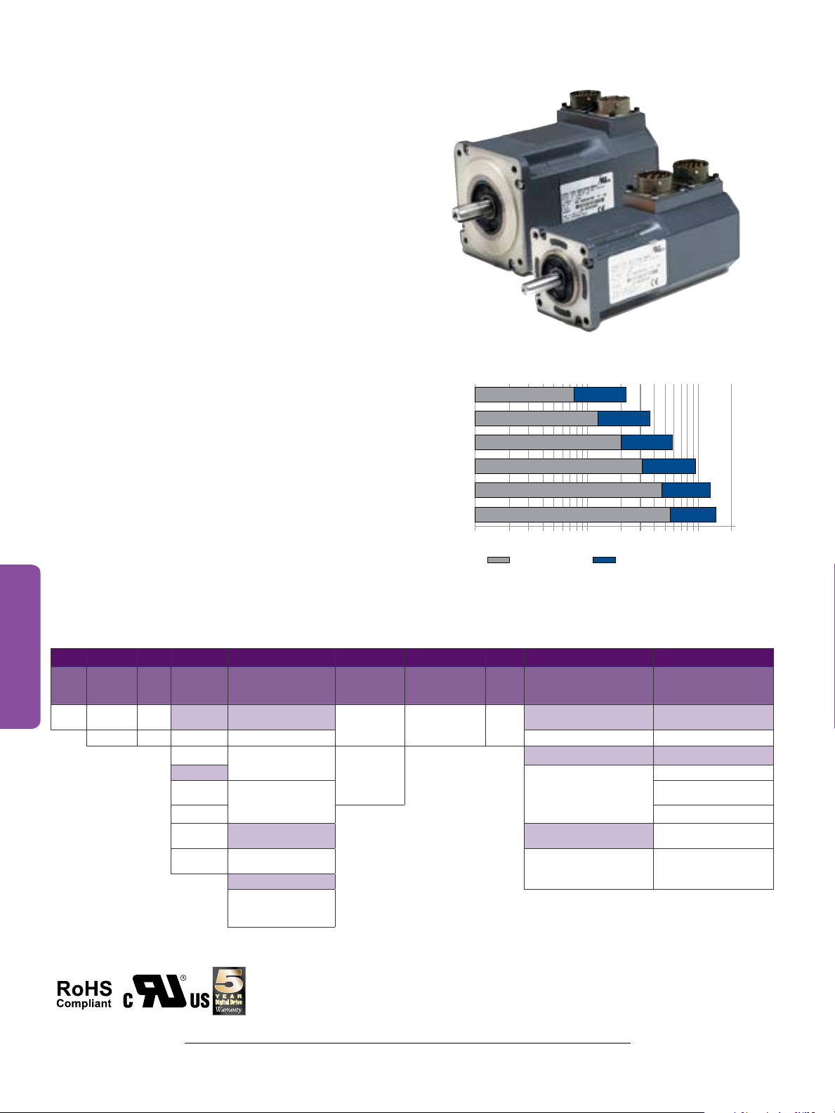
The NT motor is a compact, high performance brushless AC
servo motor designed to maximize torque and minimize size. The
NT motor uses powerful magnets and is manufactured with a
segmented core to maximize stator efficiency.
These motors are available with direct motor-to-drive connector
terminations for Control Techniques' brand Unidrive M, Digitax ST
and Epsilon EP servo drives – cable lengths up to 20 ft are available.
Key Features
• Torque range: 7.5 to 56 lb-in (0.85 to 6.3 Nm)
• Very low inertia for high acceleration and cycle rates
• English (NEMA 23 or 34) or Metric (IEC- 72-1) flanges
• Available with or without holding brakes
• Direct connect available – no additional cables required!
• Flying-lead cabling option (ex: NTE-320-LONS-0005)
with improved ingress protection; flying leads
are available with or without MS connectors
• IP65 conformance (IP67S and IP68S optional)
• Standard 2048 encoder
• Installed shaft seal are standard with all motors
• Optional white epoxy food-grade finish
110 100
7.5
12.5
20
Continuous (lb-in) Peak (lb-in)
22.5
32
47
56 166
37.5
59.0
94.5
141
NT Motor 230 V Order Information
Use the information below to create an order code for an NT Motor (top row is an example).
Approvals
36
NT E 2 07 T B N S DP 10
Mounting
Motor
Flange
NT E = English 2 = 2
M = Metric 3 = 3
Frame
Rated
Size
Torque
(in)
(lb-in)
‡
2-in frame IP65
‡
07 = 7.5 C = MS connector 00 = Std. configuration 00 = Std. configuration
12 = 12.5
3-in frame
20 = 20
30 = 32 15 = 15-ft leads
45 = 47 IP67S
55 = 56
Lead Configuration
L = Flying leads
(no connectors)
T = MS style connector
on flying leads
E = 90° circular
Euro style
IP68S
F = Flying lead
and white epoxy
food-grade finish
Brake
(24 V)
O = Unbraked
B = Holding
Brake
Feedback Device Inertia
N = Incremental
encoder 2048 ppr
S = Low
Feedback Cable Connectors
/ Optional Finish
Lead Configuration
C, L, T, E
Lead Configuration T Lead Config L, T And F
DP = Flying lead with molded
15-pin feedback connector to
Digitax ST, Unidrive SP
and Epsilon EP
Lead Configurations
C, L, T, E, F
E0 = White epoxy food-grade
finish applied to
standard motor*
* Include this code when ordering “F” type lead configuration
NOTES:
‡
2 = 2-in NEMA 23
‡3 = 3-in NEMA 34
Lead Configuration
XX = Custom lengths
available up to 20 ft max.
in 2-ft increments
Cable Length
05 = 5-ft leads
10 = 10-ft leads
20 = 20-ft leads
C, L, T, E
NT MOTORS
2-inch Frame Ratings and Dimensions
NT Motor 2-inch Frame Ratings and Dimensions
Motor Frame Size (in) 2
Voltage (Vrms) 230
Model NT-207 NT-212
Continuous Stall Torque (lb-in) 7.5 12.5
Continuous Stall Torque (Nm) 0.85 1.4
Peak Torque (lb-in) 22.5 37.5
Peak Torque (Nm) 2.54 4.24
Inertia (lb-in-sec²) 0.000094 0.000164
Inertia (kgm
Cogging (lb-in) (typ.) 0.094 0.12
Cogging (Nm) (typ.) 0.011 0.014
Motor Weight (lbs) 3.0 4.0
Motor Weight (kg) 1.36 1.81
Number of Poles 8 8
Kt (lb-in/A) = 5.12 5.08
Kt (Nm/A) = 0.58 0.57
5000 rpm
NOTES:
∆t= 212 °F (100 °C) winding 104 °F (40 °C) maximum ambient; all data
subject to +/-10% tolerance
Stall torque, rated torque and power relate to maximum continuous operation
above 10 kHz drive switching frequency
Maximum intermittent winding temperature is 284 °F (140 °C)
Ke (V/k rpm) = 35 34.7
Rated Torque (lb-in) 7.50 12.50
Rated Torque (Nm) 0.85 1.4
Stall Current (A) 1.7 2.7
Rated Power (kW) 0.432 0.740
R (ph-ph) (Ohms) 11.1 4.56
L (ph-ph) (mH) 39.1 18.9
2
) 0.0000106 0.0000185
English Flange Metric Flange
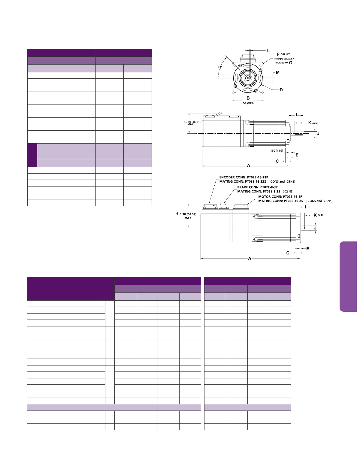
Motor Dimensions
Unbraked Length — CONS/EONS*
Braked Length — TONS/LONS/FONS 4.39 111.5 5.39 136.9 4.39 111.5 5.39 136.9
Unbraked Length — CBNS/EBNS* 6.94 176.4 7.94 201.8 6.94 176.4 7.94 201.8
Braked Length — TBNS/LBNS/FBNS 6.28 159.4 7.94 201.8 6.28 159.4 7.28 184.8
Flange Square B 2.27 57.7 2.27 57.7 2.57 65.2 2.57 65.2
Flange Thickness C 0.29 7.5 0.29 7.5 0.29 7.5 0.29 7.5
Pilot Diameter D 1.50 38.1 1.50 38.1 2.36 60.0 2.36 60.0
Pilot Thickness E 0.10 2.5 0.10 2.5 0.10 2.5 0.10 2.5
Bolt Hole Diameter F 0.21 5.2 0.21 5.2 0.23 5.8 0.23 5.8
Bolt Circle Diameter G 2.63 66.7 2.63 66.7 2.95 75.0 2.95 75.0
Connector Height — CONS
Connector Height — TONS/LONS 1.78 45.2 1.78 45.2 1.78 45.2 1.78 45.2
Connector Height — CBNS 1.98 50.4 1.98 50.4 1.98 50.4 1.98 50.4
Connector Height — TBNS/LBNS 1.78 45.2 1.78 45.2 1.78 45.2 1.78 45.2
Shaft Length I 1.21 30.7 1.21 30.7 0.93 23.5 0.93 23.5
Shaft Diameter J 0.37 9.5 0.37 9.5 0.43 11.0 0.43 11.0
Keyway Length (min) K 0.70 17.8 0.70 17.8 0.51 13.0 0.51 13.0
Keyway Depth L 0.08 2.0 0.08 2.0 0.08 2.1 0.08 2.1
Keyway Width M 0.13 3.2 0.13 3.2 0.16 4.0 0.16 4.0
NOTE:
*Not all variations are represented above; see our website for complete mechanical dimension drawings
A
H
Shaft Key Dimensions Shaft Key Dimensions
NTE-207 NTE-212 NTM-207 NTM-212
(in) (mm) (in) (mm) (in) (mm) (in) (mm)
5.55 141.0 6.55 166.4 5.55 141.0 6.55 166.4
1.92 48.9 1.92 48.9 1.92 48.9 1.92 48.9
37
NT MOTORS
3-inch Frame Ratings and Dimensions
ENCODER CONN: PT02E-16-23P
NT Motor 3-inch Frame Ratings and Dimensions
Motor Frame Size (in) 3
Voltage (Vrms) 230
Model NT-320 NT-330 NT-345 NT-355
Continuous Stall Torque (lb-in) 19.7 31.5 47.5 55.5
Continuous Stall Torque (Nm) 2.2 3.56 5.31 6.27
Inertia (lb-in-sec
2
) 0.000328 0.000438 0.000668 0.000888
Inertia (kgm2) 0.000037 0.000049 0.000075 0.000100
Peak Torque (lb-in) 59.0 94.5 141.0 166.0
Peak Torque (Nm) 6.67 10.68 15.93 18.75
Cogging (lb-in) (typ.) 0.18 0.315 0.47 0.555
Cogging (Nm) (typ.) 0.020 0.036 0.053 0.063
Motor Weight (lbs) 6.0 7.3 10.0 12.3
Motor Weight (kg) 2.72 3.31 4.54 5.58
Number of Poles 8 8 8 8
Kt (lb-in/A) = 7.13 7.30
Kt (Nm/A) = 0.806 0.825
3000 rpm
Ke (V/k rpm) = 50.0 50.0
Rated Torque (lb-in) 47.0 55.5
Rated Torque (Nm) 5.31 6.27
Stall Current (A) 6.59 7.6
Rated Power (kW) 1.668 1.97
R (ph-ph) (Ohms) 1.3 1.0
L (ph-ph) (mH) 17.0 13.0
Kt (lb-in) = 3.50 5.04
Kt (Nm/A) = 0.40 0.569
4000 rpm
Ke (V/k rpm) = 29.0 36.0
Rated Torque (lb-in) 16.0 31.6
Rated Torque (Nm) 1.8 3.56
Stall Current (A) 5.4 6.25
Rated Power (kW) 0.757 1.49
R (ph-ph) (Ohms) 1.5 1.2
L (ph-ph) (mH) 16.0 15.0
NOTES:
∆t= 212 °F (100 °C) winding 104 °F (40 °C) maximum ambient; all data subject to +/-10% tolerance
Stall torque, rated torque and power relate to maximum continuous operation above 10 kHz drive switching frequency
Max. intermittent winding temperature is 284 °F (140 °C)
MATING CONN: PT06E-16-23S
(-CONS and -CBNS)
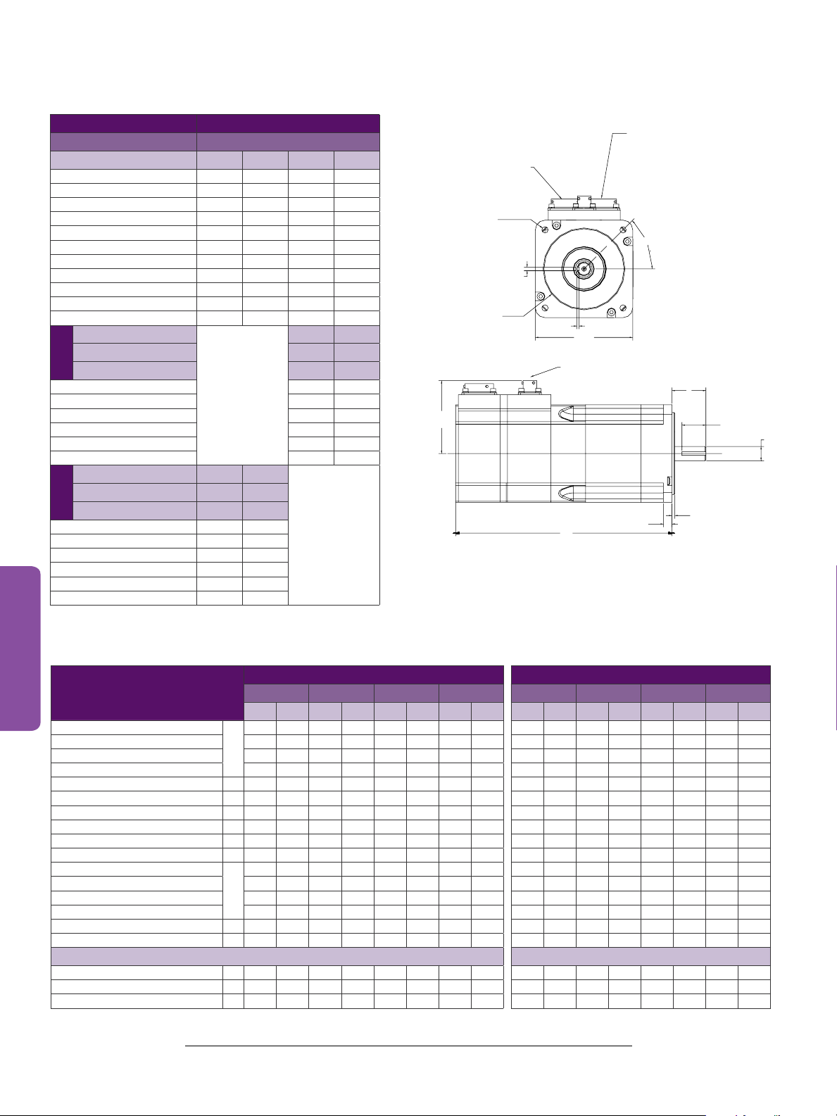
F
DRILLED THRU
(4) EQUALLY SPACED ON
2.559 [65.01]
MAX.
MOTOR CONN: PT02E-16-8P
MATING CONN:PT06E-16-8S
(-CONS and -CBNS)
G
45°
M
D
L
B
SQ. (MAX)
BRAKE CONN: PT02E-8-3P
MATING CONN: PT06E-8-3S
(-CBNS)
I
K (MIN)
J
E
A**
C
Motor Dimensions
Unbraked Length — CONS/EONS*
Braked Length — TONS/LONS/FONS 5.22 132.5 5.82 147.8 7.02 178.3 9.43 239.6 5.22 132.5 5.82 147.8 7.02 178.3 9.43 239.6
Unbraked Length — CBNS/EBNS* 7.24 184.0 7.84 199.2 9.04 229.7 11.44 290.7 7.24 184.0 7.84 199.2 9.04 229.7 11.44 290.7
Braked Length — TBNS/LBNS/FBNS 7.24 184.0 7.84 199.2 9.04 229.7 11.44 290.7 7.24 184.0 7.84 199.2 9.04 229.7 11.44 290.7
Connector Height — CONS
Connector Height — TONS/LONS 2.35 59.7 2.35 59.7 2.35 59.7 2.35 59.7 2.35 59.7 2.35 59.7 2.35 59.7 2.35 59.7
Connector Height — CBNS 2.56 65.0 2.56 65.0 2.56 65.0 2.56 65.0 2.56 65.0 2.56 65.0 2.56 65.0 2.56 65.0
Connector Height — TBNS/LBNS 2.50 63.5 2.50 63.5 2.50 63.5 2.50 63.5 2.50 63.5 2.50 63.5 2.50 63.5 2.50 63.5
NOTE:
*Not all variations are represented above; see our website for complete mechanical dimension drawings
38
English Flange Metric Flange
NTE-320 NTE-330 NTE-345 NTE-355 NTM-320 NTM-330 NTM-345 NTM-355
(in) (mm) (in) (mm) (in) (mm) (in) (mm) (in) (mm) (in) (mm) (in) (mm) (in) (mm)
5.22 132.5 5.82 147.8 7.02 178.3 9.42 239.2 5.22 132.5 5.82 147.8 7.02 178.3 9.42 239.2
A
Flange Square B 3.42 86.9 3.42 86.9 3.42 86.9 3.42 86.9 3.42 86.9 3.42 86.9 3.42 86.9 3.42 86.9
Flange Thickness C 0.30 7.6 0.30 7.6 0.30 7.6 0.30 7.6 0.30 7.6 0.30 7.6 0.30 7.6 0.30 7.6
Pilot Diameter D 2.88 73.0 2.88 73.0 2.88 73.0 2.88 73.0 3.15 80.0 3.15 80.0 3.15 80.0 3.15 80.0
Pilot Thickness E 0.10 2.5 0.10 2.5 0.10 2.5 0.10 2.5 0.12 3.0 0.12 3.0 0.12 3.0 0.12 3.0
Bolt Hole Diameter F 0.22 5.6 0.22 5.6 0.22 5.6 0.22 5.6 0.28 7.0 0.28 7.0 0.28 7.0 0.28 7.0
Bolt Circle Diameter G 3.88 98.4 3.88 98.4 3.88 98.4 3.88 98.4 3.94 100.0 3.94 100.0 3.94 100.0 3.94 100.0
2.45 62.2 2.45 62.2 2.45 62.2 2.45 62.2 2.45 62.2 2.45 62.2 2.45 62.2 2.45 62.2
H
Shaft Length I 1.21 30.7 1.21 30.7 1.21 30.7 1.21 30.7 1.21 30.7 1.21 30.7 1.21 30.7 1.21 30.7
Shaft Diameter J 0.50 12.7 0.50 12.7 0.50 12.7 0.50 12.7 0.55 14.0 0.55 14.0 0.55 14.0 0.55 14.0
Shaft Key Dimensions Shaft Key Dimensions
Keyway Length (min) K 0.84 21.3 0.84 21.3 0.84 21.3 0.84 21.3 0.79 20.0 0.79 20.0 0.79 20.0 0.79 20.0
Keyway Depth L 0.08 2.0 0.08 2.0 0.08 2.0 0.08 2.0 0.10 2.6 0.10 2.6 0.10 2.6 0.10 2.6
Keyway Width M 0.13 3.2 0.13 3.2 0.13 3.2 0.13 3.2 0.20 5.1 0.20 5.1 0.20 5.1 0.20 5.1
 Loading...