

Page 1

Advanced User Guide
Affinity
Building Automation
HVAC/R drive
Part Number: 0474-0011-03
Issue: 3
Page 2

Original Instructions
For the purposes of compliance with the EU Machinery Directive 2006/42/EC, the English version of this manual is the Original Instructions. Manuals
in other languages are Translations of the Original Instructions.
Documentation
Manuals are available to download from the following locations: http://www.drive-setup.com/ctdownloads
The information contained in this manual is believed to be correct at the time of printing and does not form part of any contract. The manufacturer
reserves the right to change the specification of the product and its performance, and the contents of the manual, without notice.
Warranty and Liability
In no event and under no circumstances shall the manufacturer be liable for damages and failures due to misuse, abuse, improper installation, or
abnormal conditions of temperature, dust, or corrosion, or failures due to operation outside the published ratings. The manufacturer is not liable for
consequential and incidental damages. Contact the supplier of the drive for full details of the warranty terms.
Environmental policy
Control Techniques Ltd operates an Environmental Management System (EMS) that conforms to the International Standard ISO 14001.
Further information on our Environmental Policy can be found at: http://www.drive-setup.com/environment
Restriction of Hazardous Substances (RoHS)
The products covered by this manual comply with European and International regulations on the Restriction of Hazardous Substances including EU
directive 2011/65/EU and the Chinese Administrative Measures for Restriction of Hazardous Substances in Electrical and Electronic Products.
Disposal and Recycling (WEEE)
When electronic products reach the end of their useful life, they must not be disposed of along with domestic waste but should be recycled
by a specialist recycler of electronic equipment. Control Techniques products are designed to be easily dismantled into their major
component parts for efficient recycling. The majority of materials used in the product are suitable for recycling.
Product packaging is of good quality and can be re-used. Large products are packed in wooden crates. Smaller products are packaged
in strong cardboard cartons which have a high recycled fibre content. Cartons can be re-used and recycled. Polythene, used in protective
film and bags for wrapping the product, can be recycled. When preparing to recycle or dispose of any product or packaging, please
observe local legislation and best practice.
REACH legislation
EC Regulation 1907/2006 on the Registration, Evaluation, Authorisation and restriction of Chemicals (REACH) requires the supplier of an article to
inform the recipient if it contains more than a specified proportion of any substance which is considered by the European Chemicals Agency (ECHA)
to be a Substance of Very High Concern (SVHC) and is therefore listed by them as a candidate for compulsory authorisation.
Further information on our compliance with REACH can be found at: http://www.drive-setup.com/reach
Registered Office
Nidec Control Techniques Ltd
The Gro
Newtown
Powys
SY16 3BE
UK
Registered in England and Wales. Company Reg. No. 01236886.
Copyright
The contents of this publication are believed to be correct at the time of printing. In the interests of a commitment to a policy of continuous development
and improvement, the manufacturer reserves the right to change the specification of the product or its performance, or the contents of the guide, without
notice.
All rights reserved. No parts of this guide may be reproduced or transmitted in any form or by any means, electrical or mechanical including
photocopying, recording or by an information storage or retrieval system, without permission in writing from the publisher.
Copyright © April 2018 Nidec Control Techniques Ltd
Page 3

Contents
1 Parameter structure.......................................................................................................5
1.1 Menu 0 ...................................................................................................................................................5
1.2 Advanced menus ...................................................................................................................................8
1.3 Solutions Modules .................................................................................................................................8
1.4 Drive and Building Automation Network (BAN) Interface software version ...........................................8
2 Keypad and display .......................................................................................................9
2.1 Understanding the display .....................................................................................................................9
2.2 Keypad operation ..................................................................................................................................9
2.3 Status mode ........................................................................................................................................10
2.4 Parameter view mode ..........................................................................................................................10
2.5 Edit mode ............................................................................................................................................10
2.6 Parameter access level and security ...................................................................................................12
2.7 Alarm and trip display ..........................................................................................................................13
2.8 Keypad control mode ...........................................................................................................................13
2.9 Drive reset ...........................................................................................................................................13
2.10 Second motor parameters ...................................................................................................................13
3 Parameter x.00 .............................................................................................................14
3.1 Parameter x.00 reset ...........................................................................................................................14
3.2 Saving parameters in drive EEPROM .................................................................................................14
3.3 Loading defaults ..................................................................................................................................15
3.4 SMARTCARD transfers .......................................................................................................................15
3.5 Display non-default values or destination parameters .........................................................................15
4 Typical parameter description format .......................................................................16
4.1 Parameter ranges and variable maximums: ........................................................................................17
4.2 Sources and destinations ....................................................................................................................20
4.3 Update rates ........................................................................................................................................20
5 Advanced parameter descriptions.............................................................................22
5.1 Overview ..............................................................................................................................................22
5.2 Feature look-up table ...........................................................................................................................23
5.3 Menu 1: Frequency/speed reference ...................................................................................................26
5.4 Menu 2: Ramps ...................................................................................................................................40
5.5 Menu 3: Speed feedback and speed control .......................................................................................49
5.6 Menu 4: Torque and current control ....................................................................................................60
5.7 Menu 5: Motor control ..........................................................................................................................77
5.8 Menu 6: Sequencer and clock .............................................................................................................95
5.9 Menu 7: Analog I/O ............................................................................................................................111
5.10 Menu 8: Digital I/O .............................................................................................................................122
5.11 Menu 9: Programmable logic, motorized pot and binary sum ...........................................................130
5.12 Menu 10: Status and trips ..................................................................................................................140
5.13 Menu 11: General drive set-up ..........................................................................................................159
5.14 Menu 12: Threshold detectors, variable selectors and brake control function ...................................172
5.15 Menu 13: Not used ............................................................................................................................184
5.16 Menu 14: Advanced process PID ......................................................................................................186
5.17 Menus 15 and 16: Solutions Module slots .........................................................................................200
5.18 Menu 17: Building Automation Interface ............................................................................................201
5.19 Menu 18: Application menu 1 ............................................................................................................207
5.20 Menu 19: Application menu 2 ............................................................................................................208
5.21 Menu 20: Application menu 3 ............................................................................................................209
5.22 Menu 21: Second motor parameters .................................................................................................210
5.23 Menu 22: Additional menu 0 set-up ...................................................................................................217
5.24 32 bit parameters ...............................................................................................................................218
6 PC communications protocol...................................................................................219
6.1 ANSI communications protocol ..........................................................................................................219
Affinity Advanced User Guide 3
Issue Number: 3
Page 4

6.2 CT Modbus RTU specification .......................................................................................................... 221
7 Building Automation Network ................................................................................. 226
7.1 Introduction ....................................................................................................................................... 226
7.2 BACnet ............................................................................................................................................. 226
7.3 Metasys N2 ....................................................................................................................................... 230
8 Performance .............................................................................................................. 234
8.1 Digital speed reference ..................................................................................................................... 234
8.2 Analog reference .............................................................................................................................. 234
8.3 Analog outputs .................................................................................................................................. 234
8.4 Digital inputs and outputs ................................................................................................................. 234
8.5 Current feedback .............................................................................................................................. 235
8.6 Bandwidth ......................................................................................................................................... 235
9 Rotor Flux Control (RFC) mode............................................................................... 236
9.1 Introduction ....................................................................................................................................... 236
9.2 Setting up the RFC mode ................................................................................................................. 236
9.3 Further Tuning .................................................................................................................................. 236
4 Affinity Advanced User Guide
Issue Number: 3
Page 5

Parameter
*
*
Menu 0
....XX.00....
0.50
0.49
0.48
0.47
0.46
0.01
0.02
0.03
0.04
0.05
Moves
between
parameters
M
e
n
u
4
1
M
e
n
u
1
M
e
n
u
2
M
e
n
u
2
0
Moves between Menus
4
1
.
5
0
4
1
.
4
9
4
1
.
4
8
4
1
.
4
7
4
1
.
4
6
4
1
.
0
1
4
1
.
0
2
4
1
.
0
3
4
1
.
0
4
4
1
.
0
5
1
.
0
1
1
.
0
2
1
.
0
3
1
.
0
4
1
.
0
5
1
.
5
0
1
.
4
9
1
.
4
8
1
.
4
7
1
.
4
6
4
1
.
5
1
Menu 0
0.04
0.05
0.06
Menu 2
2.21
Menu 1
1.14
Menu 4
4.07
5
0
150
0
150
5
structure
Keypad and
display
Parameter x.00
Parameter
description format
Advanced parameter
descriptions
PC comms
protocol
Building automation
network
Performance RFC mode
1 Parameter structure
The drive parameter structure consists of menus and parameters.
The drive initially powers up so that only menu 0 can be viewed. The up
and down arrow buttons are used to navigate between parameters and
once level 2 access (L2) has been enabled in Pr 0.49, and the left and
right buttons are used to navigate between menus. For further
information, see section 2.6 Parameter access level and security on
page 12.
Figure 1-1 Parameter navigation
* can only be used to move between menus if L2 access has
been enabled (Pr 0.49).
The menus and parameters roll over in both directions; i.e. if the last
parameter is displayed, a further press will cause the display to rollover
and show the first parameter.
When changing between menus the drive remembers which parameter
was last viewed in a particular menu and thus displays that parameter.
Figure 1-2 Menu structure
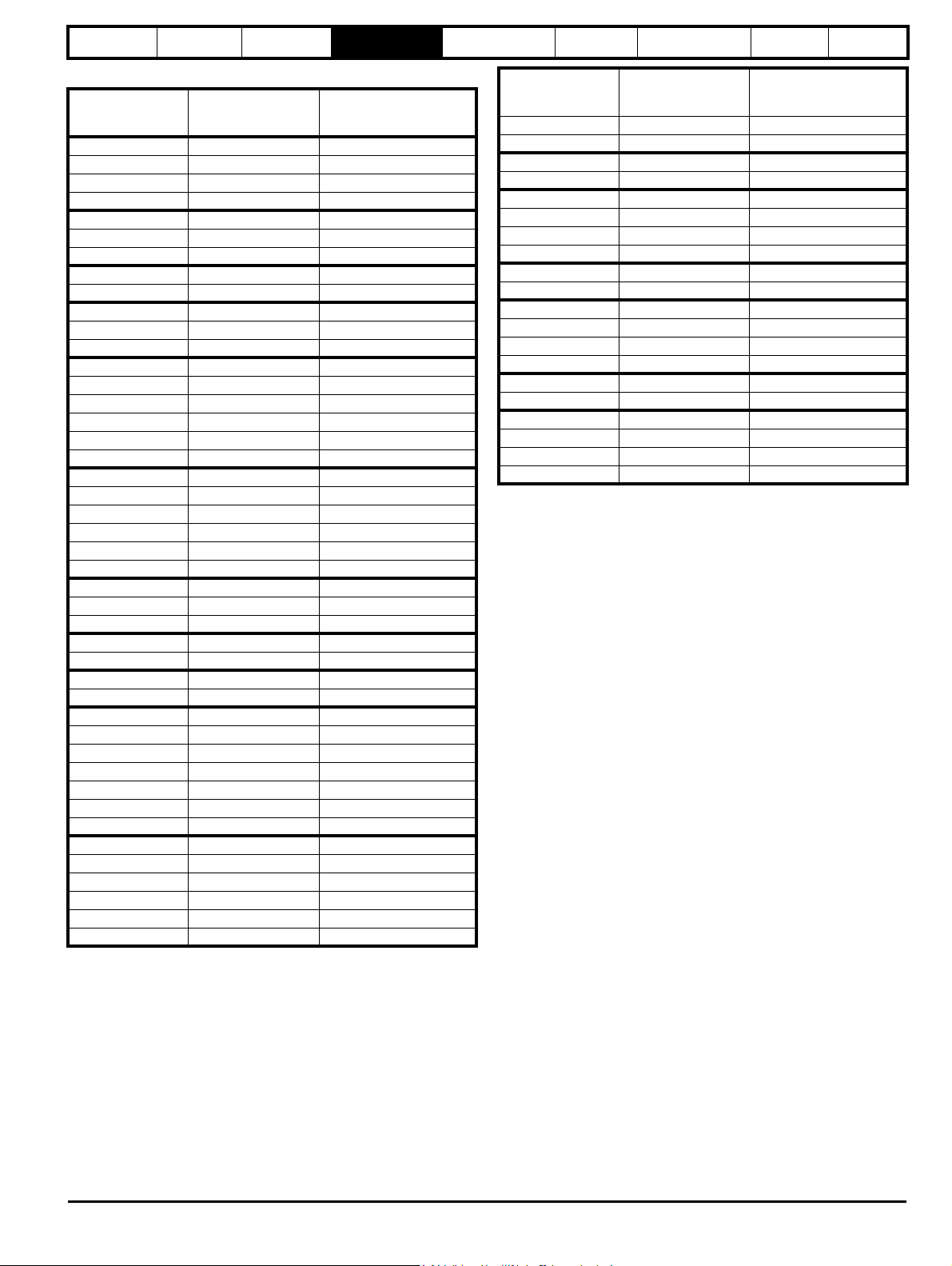
1.1 Menu 0
Menu 0 has up to 19 fixed parameters and 40 programmable parameters
that are defined in menu 11 and menu 22. Menu 0 parameters are
copies of advanced menu parameters, and although these parameters
are accessible via drive serial comms, they are not accessible to any
Solutions Modules. All menu 0 read/write parameters are saved on
exiting the edit mode. Table 1-1 gives the default structure for each drive
type setting. Where alternative parameters are selected with motor map
2 from menu 21 these are shown below the motor map 1 parameters.
Figure 1-3 Menu 0 cloning‘
Affinity Advanced User Guide 5
Issue Number: 3
Page 6

Parameter
structure
Keypad and
display
Parameter x.00
Parameter
description format
Advanced parameter
descriptions
PC comms
protocol
Building automation
network
Performance RFC mode
Menu 0 is used to bring together various commonly used parameters for basic easy set up of the drive. All the parameters in menu 0 appear in other
menus in the drive (denoted by {…}).
Menus 11 and 22 can be used to change most of the parameters in menu 0. Menu 0 can also contain up to 59 parameters by setting up menu 22.
Table 1-1 Menu 0 parameters
Range(
Parameter
0.00 xx.00 {x.00} 0 to 32,767 0
0.01 Minimum reference clamp {1.07} ±3,000.0Hz
0.02 Maximum reference clamp {1.06} 0 to 3,000.0Hz
0.03 Acceleration rate {2.11}
0.04 Deceleration rate {2.21}
0.05 Reference select {1.14} A1.A2 (0), A1.Pr (1), A2.Pr (2), Pr (3), PAd (4), Prc (5) A1.A2 (0)
0.06 Current limit {4.07} 0 to CURRENT_LIMIT_MAX % 110
OL> Voltage mode select {5.14}
0.07
RFC> Speed controller P gain {3.10}
OL> Voltage boost {5.15}
0.08
RFC> Speed controller I gain {3.11} 0.00 to 655.35 1/rad 0.10
OL> Dynamic V/F {5.13} OFF (0) or On (1)
0.09
RFC> Speed controller D gain {3.12}
OL> Estimated motor speed {5.04} ±180,000 rpm
0.10
RFC> Motor speed {3.02} ±SPEED_MAX rpm
0.11 Drive output frequency {5.01} ±SPEED_FREQ_MAX Hz ±1250 Hz
0.12 Total motor current {4.01} 0 to DRIVE_CURRENT_MAX A
0.13 Percentage load {4.20} ±USER_CURRENT_MAX %
0.14 Ramp mode select {2.04}
0.15 Sleep/wake threshold {6.53} ±SPEED_FREQ_MAX Hz/rpm 0.0
0.16 Sleep/wake delay time {6.54} 0.0 to 250.0 s 10.0
0.17 RFC> Current demand filter 1 {4.12}
0.18 Spin start boost {5.40} 0.0 to 10.0
0.19 Analog input 2 mode {7.11}
0.20 Analog input 2 destination {7.14}Pr 0.00 to Pr 50.99 Pr 1.37
0.21 Analog input 3 mode {7.15}
0.22 Date {6.16} 0 to 311299
0.23 Time {6.17} 0.00 to 23.59
0.24 Date/Time selector {6.19} 0 to 5 3
0.25 Date format {6.20} Std (0), Std.ds (1), US (2), US.ds (3) EUR> Std (0), USA> US (2)
0.26 Low load detection level {4.27} 0.0 to 100.0 % 0.0
Low load detection speed / frequency
0.27
threshold
0.28 Trip on abnormal load detection {4.29} OFF (0) or On (1) OFF (0)
0.29 SMARTCARD parameter data {11.36 } 0 to 999 0
0.30 Parameter cloning {11 .4 2} nonE (0), rEAd (1), Prog (2), AutO (3), boot (4) nonE (0)
0.31 Drive rated voltage {11 .3 3} 200 (0), 400 (1), 575 (2), 690 (3) V
0.32 Drive current scaling {11.32} 0.00 to 9999.99A
0.33 Catch a spinning motor {6.09} 0 to 3 0 to 1 0 1
0.34 User security code {11.3 0} 0 to 999 0
0.35 PC comms mode {11.24} AnSI (0), rtU (1), Lcd (2) rtU (1)
0.36 PC comms baud rate {11. 25}
0.37 PC comms address {11.23} 0 to 247 1
0.38 Hold zero speed / Motor pre-heat enable {6.08} OFF (0) or On (1) OFF (0)
0.39 Motor pre-heat current magnitude {6.52} 0 to 100 % 0
0.40 Autotune {5.12} 0 to 2 0 to 4 0
0.41 Maximum switching frequency {5.18} 3 (0), 4 (1), 6 (2), 8 (3), 12 (4), 16 (5) kHz 3 (0)
Ur (1), Fd (2), Ur_Auto (3),
{4.28} 0.0 to +SPEED_FREQ_MAX Hz/rpm 0.0
OL RFC OL RFC
0.0 to 3,200.0
s/100Hz
0.0 to 3,200.0
s/100Hz
Ur_S (0),
Ur_I (4), SrE (5)
0.0 to 25.0% of motor
rated voltage
FASt (0)
Std ( 1)
Std. hV (2 )
0-20 (0), 20-0 (1), 4-20tr (2), 20-4tr (3),
4-20 (4), 20-4 (5), VOLt (6)
0-20 (0), 20-0 (1), 4-20tr (2), 20-4tr (3),
4-20 (4), 20-4 (5), VOLt (6), th.SC (7),
4800 (4), 9600 (5), 19200 (6), 38400 (7),
th (8), th.diSp (9)
300 (0), 600 (1), 1200 (2), 2400 (3),
57600 (8) Modbus RTU only,
115200 (9) Modbus RTU only
) Default()
±SPEED_LIMIT_
MAX Hz/rpm
SPEED_LIMIT_
MAX Hz/rpm
0.000 to 3,200.000
s/1,000rpm
0.000 to 3,200.000
s/1,000rpm
0.0000 to 6.5535
0.0 to 25.0 ms
-1
1/rad s
0.00000 to
0.65535 (s)
FASt (0)
Std ( 1)
EUR> 50.0
USA> 60.0
EUR> 40.0
USA> 33.3
EUR> 40.0
USA> 33.3
Fd (2)
Size 1 to 3: 3.0
Size 4 & 5: 2.0
Size 6: 1.0
OFF (0)
0.0
Std ( 1)
1.0
4-20 (4)
VOLt (6)
19200 (6)
EUR> 1,500.0
USA> 1800.0
EUR> 13.333
US A > 11. 111
EUR> 13.333
US A > 11. 111
0.0300
0.00000
0.0
6 Affinity Advanced User Guide
Issue Number: 3
Page 7

Parameter
structure
0.42 No. of motor poles {5.11} 0 to 60 (Auto to 120 pole) 0 (Auto)
0.43 Motor rated power factor {5.10} 0.000 to 1.000 0.850
0.44 Motor rated voltage {5.09} 0 to AC_VOLTAGE_SET_MAX V
Motor rated full load speed (rpm)
0.45
0.46 Motor rated current {5.07} 0 to RATED_CURRENT_MAX A Drive rated current [11.3 2]
0.47 Rated frequency {5.06} 0 to 3,000.0 Hz 0 to 1,250.0 Hz
0.48 Operating mode selector {11.31} OPEn LP (1), RFC (2), OPEn LP (1) RFC (2)
0.49 Security status {11.44} L1 (0), L2 (1), Loc (2)
0.50 Software version {11.2 9} 1.00 to 99.99
0.51 Positive logic select {8.29} OFF (0) or On (1) On (1)
0.52 Timer 1 start date {9.35} 0 to 311299 0
0.53 Timer 1 start time {9.36} 0.00 to 23.59 0.00
0.54 Timer 1 stop date {9.37} 0 to 311299 0
0.55 Timer 1 stop time {9.38} 0.00 to 23.59 0.00
0.56 Timer 1 repeat function {9.39} 0 to 6 0
0.57 Timer 1 enable {9.40} OFF (0) or On (1) OFF (0)
0.58 Timer 1 destination {9.43}Pr 0.00 to Pr 50.99 Pr 0.00
Keypad and
display
Parameter
Parameter x.00
Parameter
description format
{5.08} 0 to 180,000 rpm
Advanced parameter
descriptions
OL RFC OL RFC
PC comms
protocol
) Default()
Range(
0.00 to
40,000.00 rpm
Building automation
network
400V drive: EUR> 400, USA> 460
EUR> 1,500
USA> 1,800
Performance RFC mode
200V drive: 230
575V drive: 575
690V drive: 690
EUR> 1,450.00
USA> 1,770.00
EUR> 50.0
USA> 60.0
* Modes 1 and 2 are not user saved, Modes 0, 3 and 4 are user saved
Coding Attribute
OL Open loop
rfc RFC
{X.XX} Cloned / copied advanced parameter
RW Read/write: can be written by the user
RO Read only: can only be read by the user
Bit 1 bit parameter: ‘On’ or ‘OFF’ on the display
Bi Bipolar parameter
Uni Unipolar parameter
Txt Text: the parameter uses text strings instead of numbers.
Filtered: some parameters which can have rapidly changing
FI
values are filtered when displayed on the drive keypad for
easy viewing.
Destination: This parameter selects the destination of an
DE
input or logic function.
Rating dependent: this parameter is likely to have different
values and ranges with drives of different voltage and
current ratings. Parameters with this attribute will not be
transferred to the destination drive by SMARTCARDs when
RA
the rating of the destination drive is different from the
source drive and the file is a parameter file. However, the
value will be transferred if only the current rating is different
and the file is a differences from default type file.
Not cloned / copied: not transferred to or from
NC
SMARTCARDs during cloning.
PT Protected: cannot be used as a destination.
User save: parameter saved in drive EEPROM when the
US
user initiates a parameter save.
Power-down save: parameter automatically saved in drive
EEPROM when the under volts (UV) trip occurs. Power-
PS
down save parameters are also saved in drive EEPROM
when the user initiates a parameter save.
Affinity Advanced User Guide 7
Issue Number: 3
Page 8

Parameter
structure
Keypad and
display
Parameter x.00
Parameter
description format
Advanced parameter
descriptions
PC comms
protocol
Building automation
network
Performance RFC mode
1.2 Advanced menus
The advanced menus consist of groups or parameters appropriate to a specific function or feature of the drive. These are accessible via the keypad,
drive serial comms and Solutions Modules. Advanced menu parameters can only be saved by setting Pr x.00 to 1000 and applying a reset (except
parameters shown as power-down saved which are saved automatically at power-down). The advanced menus are accessible when the user selects
L2 in Pr 11.44 (Pr 0.49 in menu 0). This can be done even if security is programmed. Pr 11. 44 can be saved in EEPROM so that either Menu 0 only,
or Menu 0 and the advanced menus are accessible at power-up.
Menu Function
1 Speed reference selection, limits and filters
2Ramps
3 Speed sensing thresholds
4 Current control
5 Motor control
6 Sequencer and clock
7 Analog I/O
8 Digital I/O
9 Programmable logic and motorised pot
10 Drive status and trip information
11 Miscellaneous
Programmable threshold, variable selector and brake control
12
function
13 Not used
14 Advanced process PID
15 Slot 1 Solutions Module menu
16 Slot 2 Solutions Module menu
17 Building Automation Network
18 User application menu 1 (saved in drive EEPROM)
19 User application menu 2 (saved in drive EEPROM)
20 User application menu 3 (not saved in drive EEPROM)
21 Second motor map
22 Additional menu 0 set-up
1.3 Solutions Modules
Any Solutions Module type is recognized with all drive types in any slots. The relevant template is used to define menu 15 for the module type
installed in slot 1 and menu 16 for slot 2.
1.4 Drive and Building Automation Network (BAN) Interface software version
This product is supplied with the latest version of software. If this product is to be used in a new or existing system with other drives, there may be
some differences between their software and the software in this product. These differences may cause this product to function differently. This may
also apply to drives returned from a Control Techniques Service Centre.
The software version of the drive can be checked by looking at Pr 11. 29 (or Pr 0.50) and Pr 11. 34. The software version takes the form of xx.yy.zz,
where Pr 11.29 displays xx.yy and Pr 11.3 4 displays zz, i.e. for software version 01.01.00, Pr 11.29 would display 1.01 and Pr 11.34 would display 0.
The software version of the Building Automation Network (BAN) Interface can be checked by looking at Pr 17.02 and Pr 17.51. The software version
takes the form of xx.yy.zz, where Pr 17.02 displays xx.yy and Pr 17.51 displays zz.
If there is any doubt, contact a Control Techniques Drive Centre.
8 Affinity Advanced User Guide
Issue Number: 3
Page 9

Parameter
Mode (black) button
Joypad
Fwd / Rev (blue) button
Stop/reset (red) button
Start (green) button
Control buttons
Help button
NOTE
Use
* keys
to select parameter for editing
To enter Edit Mode,
press key
Status
Mode
(Display
not
flashing)
Parameter
Mode
(Parameter
number
on upper
line
flashing)
Edit Mode
(Flashing character on upper line to be edited)
Change parameter values
using keys.
When returning
to Parameter
Mode use the
keys to select
another parameter
to change, if
required
To exit Edit Mode,
press key
To enter Parameter
Mode, press key or
*
Tem por ary
Parameter
Mode
(Parameter
number
on upper line
flashing)
Timeout**
Timeout**
To return to
Status Mode,
press
key
rdy 0
rpm
Est imat ed mo t or
RPM
0. 1 0 0
rpm
Est imat ed mo t or
RPM
0. 0 0 0
Fr e q u e c yn
Re f e r e c ens
0. 0 0 0
Fr e q u e c yn
Re f e r e c ens
0. 0 0 0
Fr e q u e c y
nReferecens
Timeout**
RO
parameter
R/W
parameter
structure
Keypad and
display
Parameter x.00
Parameter
description format
Advanced parameter
descriptions
PC comms
protocol
Building automation
network
Performance RFC mode
2 Keypad and display
2.1 Understanding the display
2.1.1 BA-Keypad (LCD)
The display consists of three lines of text.
The top line shows the drive status or the current menu and parameter number being viewed on the left, and the parameter value or the specific trip
type on the right.
The lower two lines show the parameter name or the help text.
Figure 2-1 BA-Keypad
The red stop button is also used to reset the drive.
2.2 Keypad operation
2.2.1 Control buttons
The keypad consists of:
1. Joypad - used to navigate the parameter structure and change parameter values.
2. Mode button - used to change between the display modes – parameter view, parameter edit, status.
3. Three control buttons - used to select Hand / Off / Auto modes
4. Help button - displays text briefly describing the selected parameter.
The Help button toggles between other display modes and parameter help mode. The up and down functions on the joypad scroll the help text to
allow the whole string to be viewed. The right and left functions on the joypad have no function when help text is being viewed.
The drive parameters are accessed as shown in Figure 2-2.
Figure 2-2 Display modes
Affinity Advanced User Guide 9
Issue Number: 3
Page 10

Parameter
structure
Keypad and
display
Parameter x.00
Parameter
description format
Advanced parameter
2.3 Status mode
In status mode, the first row displays a four letter mnemonic on the left
indicating the status of the drive together with the parameter last viewed
or edited on the right.
State
Inhibited: enable input is inactive inh
Ready: enable closed, but inverter not active rdy
Stopped: inverter active, but holding zero speed/frequency stop
Mains loss: decelerating to zero in mains loss ride-through
or stop modes
Decelerating: speed/frequency is ramping to zero after a
stop
dc injection: dc injection stop is active dc
Tripped: drive is tripped trip
Drive is running with Hand / Off / Auto disabled run
Drive is running in Auto mode auto
Drive is running in Hand mode hand
Drive is stopped off
Upper
row
acuu
dec
2.4 Parameter view mode
In this mode the first row shows the menu.parameter number on the left
and the parameter value on the right. The second row gives a parameter
value range of -9,999,999 to 9,999,999 with or without decimal points.
(32 bit parameters can have values outside this range if written by an
application module. If the value is outside this range “-------“is shown and
the parameter value cannot be changed from the keypad.) The Up and
Down keys are used to select the parameter and the Left and Right keys
are used to select the menu. In this mode the Up and Down keys are
used to select the parameter within the selected menu. Holding the Up
key will cause the parameter number to increment until the top of the
menu is reached. A single Up key action when the last parameter in a
menu is being displayed will cause the parameter number to roll over to
Pr x.00. Similarly holding the Down key will cause the parameter number
to decrement until Pr x.00 is reached and a single Down key action will
cause the parameter number to roll under to the top of the menu.
Pressing the Up and Down keys simultaneously will select Pr x.00 in the
currently selected menu.
The Left and Right keys are used to select the required menu (provided
the security has been unlocked to allow access to menus other than 0).
Holding the Right key will cause the menu number to increment until the
Menu 41 is reached. A single Right key action when Menu 41 is being
displayed will cause the menu number to roll over to 0. Similarly holding
the Left key will cause the menu number to decrement to 0 and a single
key action will cause the menu number to roll under to Menu 41.
Pressing the Left and Right keys simultaneously will select Menu 0.
The drive remembers the parameter last accessed in each menu such
that when a new menu is entered the last parameter viewed in that menu
will re-appear.
descriptions
During adjustment of a parameter value with the Up or Down keys the
display does not flash, providing the parameter value is in range, such
that the user can see the value being edited without interruption.
Adjustment of a numerical value can be done in one of two ways; firstly
by using the Up and Down keys only, the selected digit remaining the
least significant digit; and secondly by selecting each digit in turn and
adjusting them to the required value. Holding the Up or Down key in the
first method will cause the parameters value to change more rapidly the
longer the key is held, until such time that the parameters maximum or
minimum is reached. However when using the second method, an
increasing rate of change does not take place when adjusting any other
digit other than the least significant digit since a digit can only have one
of 10 different values.
Holding the Up or Down will cause an auto repeat and roll over to more
significant digits but the rate of change is unaltered. If the maximum or
minimum is exceeded when adjusting any other digit than the least
significant one, the maximum value will flash on the display to warn the
user that the maximum or minimum has been reached.
If the user releases the Up or Down key before the flashing stops the last
in range value will re-appear on the display. If the Up or Down key is held
the display will stop flashing after 3 seconds and the maximum value will
be written to the parameter.
Parameters can be set to 0 by pressing the Up and Down keys
simultaneously.
The BA-Keypad contains two menus, menu 40 and menu 41. The
parameters in these menus are listed Table 2-1 on page 11.
PC comms
protocol
Building automation
network
Performance RFC mode
2.5 Edit mode
Up and Down keys are used to increase and decrease parameter values
respectively. If the maximum value of a parameter is greater than 9 and it
is not represented by strings, then the Left and Right keys can be used
to select a digit to adjust. The number of digits which can be
independently selected for adjustment depends on the maximum value
of the parameter. Pressing the Right key when the least significant digit
is selected will cause the most significant digit to be selected, and viceversa if the Left key is pressed when the most significant digit is
selected. When a digit value is not being changed by the Up or Down
keys the selected digit flashes to indicate which one is currently
selected. For string type parameters the whole string flashes when
adjustment is not occurring because there is no digit selection.
10 Affinity Advanced User Guide
Issue Number: 3
Page 11

Parameter
structure
Keypad and
display
Parameter x.00
Parameter
description format
Advanced parameter
descriptions
PC comms
protocol
Building automation
network
Performance RFC mode
Table 2-1 Menu 40 parameter descriptions
Parameter
Range(
) Default()
40.00 Parameter 0 0 to 32767 0 RW Uni
English (0), Custom (1),
40.01 Language selection
French (2), German (3),
English (0) RW Txt US
Spanish (4), Italian (5)
40.02 Software version
40.03 Save to flash
40.04 LCD contrast
Drive and attribute database upload was
40.05
bypassed
40.06 Browsing favourites control
40.07 Keypad security code
40.08 Communication channel selection
40.09 Hardware key code
40.10 Drive node ID (Address)
40.11 Flash ROM memory size
40.19 String database version number
40.20 Screen saver strings and enable
40.21 Screen saver interval
40.22 Turbo browse time interval
Idle (0), Save (1), Restore (2),
Disable (0), Slot1 (1), Slot2 (2),
Slot3 (3), Slave (4), Direct (5)
None (0), Default (1), User (2) Default (1) RW Txt US
999999 RO Uni PT
Default (3)
Idle (0) RW Txt
0 to 31 16 RW Uni US
Updated (0), Bypass (1) RO Txt PT
Normal (0), Filter (1) Normal (0) RW Txt
0 to 999 0RWUniUS
Disable (0) RW Txt US
0 to 999 0RWUniUS
0 to 255 1RWUniUS
4Mbit (0), 8Mbit (1) RO Txt PT US
0 to 999999 RO Uni PT
0 to 600 120 RW Uni US
0 to 200ms 50ms RW Uni US
Table 2-2 Menu 41 parameter descriptions
Parameter
) Default()
Range(
41.00 Parameter 0 0 to 32767 0 RW Uni
41.01
to
Browsing filter source F01 to F50 Pr 0.00 to Pr 391.51 0RWUni
41.50
41.51 Browsing favourites control Normal (0), Filter (1) Normal (0) RW Txt
Typ e
Typ e
RW Read / Write RO Read only Uni Unipolar Bi Bi-polar
Bit Bit parameter Txt Text string FI Filtered DE Destination
NC Not cloned / copied RA Rating dependent PT Protected US User save
PS Power down save
For more information about the BA Keypad, see the SM-Keypad Plus User Guide.
Affinity Advanced User Guide 11
Issue Number: 3
Page 12

Parameter
Pr 0.00
Pr 0.01
Pr 0.02
Pr 0.03
Pr 0.49
Pr 0.50
Pr 1.00
Pr 1.01
Pr 1.02
Pr 1.03
Pr 1.49
Pr 1.50
Pr 22.00
Pr 22.01
Pr 22.02
Pr 22.03
Pr 22.28
Pr 22.29
............
............
............
............
............
............
............
............
L2 access selected
- All parameters visible
Pr 0.00
Pr 0.01
Pr 0.02
Pr 0.03
Pr 0.49
Pr 0.50
Pr 1.00
Pr 1.01
Pr 1.02
Pr 1.03
Pr 1.49
Pr 1.50
Pr 19.00
Pr 19.01
Pr 19.02
Pr 19.03
Pr 19.49
Pr 19.50
Pr 20.00
Pr 20.01
Pr 20.02
Pr 20.03
Pr 20.49
Pr 20.50
............
............
............
............
............
............
............
............
L1 access selected
- Menu 0 only visible
Pr 21.00
Pr 21.01
Pr 21.02
Pr 21.03
Pr 21.30
Pr 21.31
Pr 0.00
Pr 0.01
Pr 0.02
Pr 0.03
Pr 0.50
Pr 1.00
Pr 1.01
Pr 1.02
Pr 1.03
Pr 1.49
Pr 1.50
............
............
............
............
............
............
............
............
Pr 0.00
Pr 0.01
Pr 0.02
Pr 0.03
Pr 0.49
Pr 0.50
Pr 1.00
Pr 1.01
Pr 1.02
Pr 1.03
Pr 1.49
Pr 1.50
Pr 22.00
Pr 22.01
Pr 22.02
Pr 22.03
Pr 22.28
Pr 22.29
............
............
............
............
............
............
............
............
User security open
- All parameters: Read / Write access
User security closed
0.49 11.44
- All parameters: Read Only access
(except Pr and Pr )
Pr 22.00
Pr 22.01
Pr 22.02
Pr 22.03
Pr 22.28
Pr 22.29
Pr 0.49
Pr 21.00
Pr 21.01
Pr 21.02
Pr 21.03
Pr 21.30
Pr 21.31
Pr 21.00
Pr 21.01
Pr 21.02
Pr 21.03
Pr 21.30
Pr 21.31
structure
Keypad and
display
Parameter x.00
Parameter
description format
Advanced parameter
descriptions
PC comms
protocol
Building automation
network
Performance RFC mode
2.6 Parameter access level and security
The parameter access level determines whether the user has access to
menu 0 only or to all the advanced menus (menus 1 to 22) in addition to
menu 0.
The User Security determines whether the access to the user is read
only or read write.
Both the User Security and Parameter Access Level can operate
independently of each other as shown in the table below:
Parameter
Access Level
L1 Open RW Not visible
L1 Closed RO Not visible
L2 Open RW RW
L2 Closed RO RO
RW = Read / write access RO = Read only access
The default settings of the drive are Parameter Access Level L1 and
user Security Open, i.e. read / write access to Menu 0 with the advanced
menus not visible.
User Security
Menu 0
status
2.6.1 Access Level
The access level is set in Pr 0.49 and allows or prevents access to the
advanced menu parameters.
Advanced
menus status
2.6.3 User Security
The User Security, when set, prevents write access to any of the
parameters (other than Pr. 0.49 Access Level) in any menu.
Setting User Security
Enter a value between 1 and 999 in Pr 0.34 and press the button;
the security code has now been set to this value. In order to activate the
security, the Access level must be set to Loc in Pr 0.49. When the drive
is reset, the security code will have been activated and the drive returns
2.6.2 Changing the Access Level
The Access Level is determined by the setting of Pr 0.49 as follows:
String Value Effect
L1 0 Access to menu 0 only
L2 1 Access to all menus (menu 0 to menu 22)
The Access Level can be changed through the keypad even if the User
Security has been set.
12 Affinity Advanced User Guide
to Access Level L1. The value of Pr 0.34 will return to 0 in order to hide
the security code. At this point, the only parameter that can be changed
by the user is the Access Level Pr 0.49.
Unlocking User Security
Select a read write parameter to be edited and press the button, the
upper display will now show CodE. Use the arrow buttons to set the
security code and press the button.
With the correct security code entered, the display will revert to the
parameter selected in edit mode.
If an incorrect security code is entered the display will revert to
parameter view mode.
To lock the User Security again, set Pr 0.49 to Loc and press the
reset button.
Disabling User Security.
Unlock the previously set security code as detailed above. Set Pr 0.34 to
0 and press the button. The User Security has now been disabled,
and will not have to be unlocked each time the drive is powered up to
allow read / write access to the parameters.
Issue Number: 3
Page 13

Parameter
structure
Keypad and
display
Parameter x.00
Parameter
description format
Advanced parameter
descriptions
PC comms
protocol
Building automation
network
Performance RFC mode
2.7 Alarm and trip display
An alarm can flash alternately with the data displayed on the second row
when one of the following conditions occur. If action is not taken to
eliminate the alarm, except "Auto tune", "Lt" and "PLC", the drive may
eventually trip. Alarms flash once every 640ms except "PLC" which
flashes once every 10s. Alarms are not displayed when a parameter is
being edited.
Alarm string Alarm condition
br.rS
OVLd
hot Heatsink or control board alarms are active
Auto tune Auto tune in progress
Lt
PLC On-board PLC program is running
When a trip occurs the drive switches to status mode and "trip" is shown
on the top left and the trip string flashes on the top right. If the trip is a
power module trip and the drive is a multi-module drive, the number of
the power module that initiated the trip flashes alternately with the trip
string. The read only parameters listed below are frozen with any trip
except UV trip until the trip is cleared. For a list of the possible trip strings
see Pr 10.20. Pressing any of the parameter keys changes the mode to
the parameter view mode. If the trip is HF01 to HF16 then no key action
is recognized.
Parameter Description
1.01 Frequency reference/Speed reference
1.02 Frequency reference/Speed reference
1.03 Pre-ramp reference
2.01 Post-ramp reference
3.01 Final speed reference
3.02 Speed feedback
3.03 Speed error
3.04 Speed controller output
4.01 Current magnitude
4.02 Active current
4.17 Magnetising current
5.01 Output frequency
5.02 Output voltage
5.03 Power
5.05 DC bus voltage
7.01 Analog input 1
7.02 Analog input 2
7.03 Analog input 3
Braking resistor (Pr 10.39 > 75.0% and the
braking IGBT is active)
Motor overload (Pr 4.20 > 75% and the drive
output current > Pr 5.07)
Indicates that a limit switch is active and that it is
causing the motor to be stopped (i.e. forward
limit switch with forward reference etc.)
Mode Unit
Open loop Hz
rfc rpm
2.9 Drive reset
A drive reset is required to: reset the drive from a trip (except some
“Hfxx” trips which cannot be reset); and other functions as defined in
Section 3. A reset can be performed in four ways:
1. Stop key: If the drive has been set up such that the stop key is not
operable, then the key has a drive reset function only. When the stop
function of the stop key is enabled, a reset is initiated while the drive
is running by holding the Run key and then pressing the Stop key.
When the drive is not running the Stop key will always reset the
drive.
2. The drive resets after a 0 to 1 transition of the Drive Reset parameter
(Pr 10.33). A digital input can be programmed to change this
parameter.
3. Serial comms, fieldbus or applications Solutions Module: Drive reset
is triggered by a value of 100 being written to the User trip parameter
(Pr 10.38).
If the drive trips EEF (internal EEPROM error) then it is not possible to
reset the drive using the normal reset methods described above. 1233 or
1244 must be entered into Pr x.00 before the drive can be reset. Default
parameters are loaded after an EEF trip, and therefore the parameters
must be re-programmed as required and saved in EEPROM.
If the drive is reset after a trip from any source other than the Stop key,
the drive restarts immediately, if:
1. A non-latching sequencer is used with the enable active and one of
run forward, run reverse or run active
2. A latching sequencer is used if the enable and not stop are active
and one of run forward, run reverse or run is active.
If the drive is reset with the Stop key, the drive does not restart until a not
active to active edge occurs on run forward, run reverse or run.
2.10 Second motor parameters
An alternative set of motor parameters are held in menu 21 which can be
selected by Pr 11.45. When the alternative parameter set is being used
by the drive the ‘mot 2 is displayed on the bottom left.
2.8 Keypad control mode
The drive can be controlled from the keypad if Pr 1.14 is set to 4. The
Stop and Run keys automatically become active (the Reverse key may
be optionally enabled with Pr 6.13). The frequency/speed reference is
defined by Pr 1.17. This is a read only parameter that can only be
adjusted in status mode by pressing the Up or Down keys. If keypad
control mode is selected, then pressing the Up or Down keys in status
mode will cause the drive to automatically display the keypad reference
and adjust it in the relevant direction. This can be done whether the drive
is disabled or running. If the Up or Down keys are held the rate of
change of keypad reference increases with time. The units used for to
display the keypad reference for different modes are given below.
Affinity Advanced User Guide 13
Issue Number: 3
Page 14

Parameter
structure
Keypad and
display
Parameter x.00
Parameter
description format
Advanced parameter
descriptions
PC comms
protocol
Building automation
network
Performance RFC mode
3 Parameter x.00
Parameter x.00 is available in all menus and has the following functions.
Value Action
1000
1001 Save parameters under all conditions
1070 Reset all Solutions Modules
1233 Load standard defaults
1244 Load US defaults
1253 Change drive mode with standard defaults
1254 Change drive mode with US defaults
1255
1256
2001
3yyy
4yyy
5yyy
6yyy Transfer SMARTCARD data block yyy to the drive
7yyy Erase SMARTCARD data block yyy
8yyy Compare drive parameters with block yyy
9555 Clear SMARTCARD warning suppression flag
9666 Set SMARTCARD warning suppression flag
9777 Clear SMARTCARD read-only flag
9888 Set SMARTCARD read-only flag
9999 Erase SMARTCARD
*12000 Display non-default values only
*12001 Display destination parameters only
*These functions do not require a drive reset to become active. All other
functions require a drive reset.
3.1 Parameter x.00 reset
When an action is started by setting Pr x.00 to one of the above values
and initiating a drive reset this parameter is cleared when the action is
completed successfully. If the action is not started, e.g. because the
drive is enabled and an attempt is made to load defaults, etc., Pr x.00 is
not cleared and no trip is produced.
If the action is started and then fails for some reason, a trip is always
produced and Pr x.00 is not cleared. It should be noted that parameter
saves etc. can also be initiated with the cloning parameter (Pr 11. 42). If
actions that can be initiated by either parameter are started and then
completed successfully, Pr x.00 and Pr 11.42 are cleared if they have a
value less than 3.
It should be noted that there could be some conflict between the actions
of Pr x.00 and Pr 11.42 (Parameter cloning) when the drive is reset. If
Pr 11.42 has a value of 1 or 2 and a valid action is required from the
value of Pr x.00, then only the action required by Pr x.00 is performed.
Pr x.00 and Pr 11. 42 are then reset to zero. If Pr 11. 42 has a value of 3
or 4 it will operate correctly causing parameters to be saved to the
SMARTCARD each time a parameter save is performed.
Save parameters when under voltage is not active
(Pr 10.16 = 0) and 48V supply is not active (Pr 6.44 = 0).
Change drive mode with standard defaults (excluding
menus 15 to 20)
Change drive mode with US defaults (excluding menus
15 to 20)
Transfer drive parameter to a card and create a bootable
difference from default SMARTCARD block with data
block number 1 and clear Pr 11. 42. If data block 1 exists
it is over written.
Transfer drive EEPROM data to a SMARTCARD block
number yyy
Transfer drive data as difference from defaults to
SMARTCARD block number yyy
Transfer drive ladder program to SMARTCARD block
number yyy
3.2 Saving parameters in drive EEPROM
Drive parameters are saved to the drive EEPROM by setting Pr x.00 to
1000 or 1001 and initiating a drive reset. In addition to user saved
parameters, power down save parameters are also saved by these
actions and/or by changing the drive mode, but not by any other actions
that result in parameters being saved to drive EEPROM (i.e. loading
defaults). Power down save parameters are not saved at power down
unless the drive is supplied from a normal line power supply, thereby
giving the user the option of saving these parameters when required.
When the parameter save is complete, Pr x.00 is reset to zero by the
drive. Care should be taken when saving parameters because this
action can take between 400ms and several seconds depending on how
many changes are stored in the EEPROM. If the drive is powered down
during a parameter save it is possible that data may be lost. When the
drive is operating from a normal line power supply then it will stay active
for a short time after the power is removed, however, if the drive is being
powered from a 24V control supply, or it is being operated from a low
voltage battery supply, the drive will power down very quickly after the
supply is removed. The drive provides two features to reduce the risk of
data loss when the drive is powered down:-
1. If Pr x.00 is set to 1000 a parameter save is only initiated on drive
reset if the drive is supplied from a normal line power supply (Pr
10.16 = 0 and Pr 6.44 = 0). 1001 must be used to initiate a save if
the drive is not supplied from a normal line power supply.
2. Two banks of arrays are provided in EEPROM to store the data.
When a parameter save is initiated the data is stored in a new bank
and only when the data store is complete does the new bank
become active. If the power is removed before the parameter save is
complete, a SAVE.Er trip (user save parameter save error) or
PSAVE.Er trip (power down save parameter save error) will be
produced when the drive is powered up again, indicating that the
drive has reverted to the data that was saved prior to the last
parameter save.
The second feature will significantly reduce the possibility of completely
invalidating all saved data, which would result in an EEF trip on the next
power-up. However the following points should be noted:
1. If the power is removed during a parameter save the current data
that is being saved to the EEPROM that is different from the last
data saved in the EEPROM will be lost and a SAVE.Er or PSAVE.Er
trip will occur on power-up.
2. This feature does not apply when user save parameters are saved
automatically by adjusting the values in menu 0 with an LED keypad.
However, the time taken to save parameters in this way is very short,
and is unlikely to cause data loss if the power is removed after the
parameter has been changed. It should be noted that any parameter
changes made in this way are included in the currently active bank in
the EEPROM, so that if the power is removed during a subsequent
save initiated via Pr x.00 that results in an SAVE.Er trip, the changes
made via menu 0 will be retained and not lost.
3. User save parameters are saved to drive EEPROM after a transfer
of data from an electronic nameplate in an encoder.
4. User save parameters are saved to drive EEPROM after a transfer
of data from a SMARTCARD.
5. This feature is not provided for data saved to a SMARTCARD, and
so it is possible to corrupt the data files on a SMARTCARD if the
power is removed when data is being transferred to the card.
6. User save parameters are saved to drive EEPROM after defaults
are loaded.
7. When the drive mode is changed all data in the EEPROM is deleted
and then restored with the defaults for the new mode. If the power is
removed during a change of drive mode, an EEF trip is likely to
occur on the next power-up. After a change of drive mode the power
down save parameters are also saved.
14 Affinity Advanced User Guide
Issue Number: 3
Page 15

Parameter
structure
8. As these parameters are not saved if the power is removed unless
the drive is supplied with a normal line power supply, this ensures
that the power down save parameters are always stored correctly for
the new drive mode. The first time parameters are saved after the
change of drive mode, however the save will take slightly longer
than a normal parameter save.
9. When an Solutions Modules is changed for a different type in a slot,
or a module is inserted when one was not present previously or a
module is removed the EEPROM is forced to re-initialise itself on the
next parameter saves. On the first parameter save one bank is
cleared and then written to, and on the next parameter save the
other bank is cleared and re-written. Each of these parameter saves
takes slightly longer than a normal parameter save.
Keypad and
display
Parameter x.00
Parameter
description format
Advanced parameter
3.3 Loading defaults
When defaults are loaded the user save parameters are automatically
saved to the drive EEPROM in all modes. Standard defaults are loaded
by setting 1233 in Pr x.00 performing a drive reset.
The following differences from standard defaults are available when
different values are set in Pr x.00.
US Default Differences (Pr x.00 = 1244 and perform a drive reset)
descriptions
PC comms
protocol
Building automation
network
Performance RFC mode
Pr Description Default Modes
Max reference
1.06
clamp
Max reference
1.06
clamp
2.08 Standard ramp volts 775V Open-loop, RFC 400V
5.06 Rated frequency 60.0Hz Open-loop All
5.08 Rated load rpm 1800rpm Open-loop All
5.08 Rated load rpm 1770rpm RFC All
5.09 Rated voltage 460V Open-loop, RFC 400V
6.20 Date format US (2) Open-loop, RFC All
M2 Max reference
21.01
clamp
M2 Max reference
21.01
clamp
M2 Rated
21.06
frequency
21.09 M2 Rated voltage 460V Open-loop, RFC 400V
60.0Hz Open-loop All
1800rpm RFC All
60.0Hz Open-loop All
1800rpm RFC All
60.0Hz Open-loop All
Voltage
rating
3.4 SMARTCARD transfers
Drive parameters, set-up macros and internal ladder programs can be
transferred to/from SMARTCARDs. See Pr 11.36 to Pr 11.40.
3.5 Display non-default values or
destination parameters
If a value of 12000 is written to Pr x.00, then only parameters that are
different from the last defaults loaded and Pr x.00 are displayed. If a
value of 12001 is written to Pr x.00, then only destination parameters are
displayed. This function is provided to aid locating destination clashes if
a dESt trip occurs.
Affinity Advanced User Guide 15
Issue Number: 3
Page 16

Parameter
NOTE
structure
Keypad and
display
Parameter x.00
Parameter
description format
Advanced parameter
descriptions
PC comms
protocol
Building automation
network
Performance RFC mode
4 Typical parameter description format
In the sections which follow, typical parameter descriptions are given for each advanced parameter set. Each parameter has its own detailed
information block as shown here.
5.11 Number of motor poles
Drive modes
Coding
Range Open-loop, RFC 0 to 60 (Auto to 120 POLE)
Default Open-loop, RFC
Second motor
parameter
Update rate
The first row gives the menu parameter number and name. The other rows describe the following information:-
Drive modes
The drive modes are the modes in which this parameter is accessible. If the parameter is not present, the parameter is skipped when accessing it via
the keypad.
The following types of parameter are possible:
Open-loop - The control strategy is V/F mode with fixed boost or open-loop vector control.
RFC - The control strategy is rotor flux oriented vector control with closed-loop current operation for induction motors without position feedback.
Coding
This guide will show all bit parameters (with the Bit coding), as having a parameter range of "0 to 1", and a default value of either "0" or "1". This
reflects the value seen through serial communications. The bit parameters will be displayed on the BA-Keypad as being "OFF" or "On" ("OFF"= 0,
"On" = 1).
The coding defines the attributes of the parameter as follows:
Open-loop, RFC
Bit SP FI DE Txt VM DP ND RA NC NV PT US RW BU PS
1 111
0 (Auto)
3 (6 POLE)
Open-loop, RFC Pr 21.11
Background read
Coding Attribute
Bit 1 bit parameter
SP Spare: not used
Filtered: some parameters which can have rapidly changing values are filtered when displayed on
FI
the drive keypad for easy viewing.
DE Destination: indicates that this parameter can be a destination parameter.
Txt Text: the parameter uses text strings instead of numbers.
VM Variable maximum: the maximum of this parameter can vary.
DP Decimal place: indicates the number of decimal places used by this parameter.
No default: when defaults are loaded (except when the drive is manufactured or on EEPROM
ND
failure) this parameter is not modified.
Rating dependent: this parameter is likely to have different values and ranges with drives of different
voltage and current ratings. Parameters with this attribute will not be transferred to the destination
drive by SMARTCARDs when the rating of the destination drive is different from the source drive
RA
and the file is a parameter file. However, the value will be transferred if only the current rating is
different and the file is a differences from default type file.
NC Not cloned / copied: not transferred to or from SMARTCARDs during cloning / copying.
NV Not visible: not visible on the keypad.
PT Protected: cannot be used as a destination.
US User save: saved in drive EEPROM when the user initiates a parameter save.
RW Read/write: can be written by the user.
Bit default one/unsigned: Bit parameters with this flag set to one have a default of one (all other bit
BU
parameters have a default of zero. Non-bit parameters are unipolar if this flag is one.
Power-down save: parameter automatically saved in drive EEPROM when the under volts (UV) trip
PS
occurs. Power-down save parameters are also saved in drive EEPROM when the user initiates a
parameter save.
16 Affinity Advanced User Guide
Issue Number: 3
Page 17

Parameter
structure
Keypad and
display
Parameter x.00
Parameter
description format
Advanced parameter
descriptions
PC comms
protocol
Building automation
network
Performance RFC mode
4.1 Parameter ranges and variable maximums:
The two values provided define the minimum and maximum values for the given parameter. In some cases the parameter range is variable and
dependant on either:-
• other parameters,
• the drive rating,
• drive mode
• or a combination of the above.
The values given in Table 4-1 are the variable maximums used in the drive.
Table 4-1 Definition of parameter ranges & variable maximums
Maximum Definition
SPEED_FREQ_MAX
[Open-loop 3000.0Hz,
RFC 40000.0rpm]
SPEED_LIMIT_MAX
[40000.0rpm]
SPEED_MAX
[40000.0rpm]
RATED_CURRENT_MAX
[9999.99A]
DRIVE_CURRENT_MAX
[9999.99A]
AC_VOLTAGE_SET_MAX
[690V]
AC_VOLTAGE_MAX
[930V]
dc _VOLTAGE_SET_MAX
[1150V]
dc _VOLTAGE_MAX
[1190V]
Maximum speed (RFC mode) reference or frequency (open-loop mode) reference
If Pr 1.08 = 0: SPEED_FREQ_MAX = Pr 1.06
If Pr 1.08 = 1: SPEED_FREQ_MAX is Pr 1.06 or – Pr 1.07 whichever is the largest
(If the second motor map is selected Pr 21.01 is used instead of Pr 1.06 and Pr 21.02 instead of Pr 1.07)
Maximum applied to speed reference limits
In RFC mode SPEED_LIMIT_MAX = 40,000rpm.
Maximum speed
This maximum is used for some speed related parameters in menu 3. To allow headroom for overshoot etc. the
maximum speed is twice the maximum speed reference.
SPEED_MAX = 2 x SPEED_FREQ_MAX
Maximum motor rated current
RATED_CURRENT_MAX = 1.36 x K
The motor rated current can be increased above K
.
C
up to a level not exceeding 1.36 x KC). (Maximum motor
C
rated current is the maximum normal duty current rating.)
The actual level varies from one drive size to another, refer to Table 4-2.
Maximum drive current
The maximum drive current is the current at the over current trip level and is given by:
DRIVE_CURRENT_MAX = K
/ 0.45
C
Maximum output voltage set-point
Defines the maximum motor voltage that can be selected.
200V drives: 240V, 400V drives: 480V
575V drives: 575V, 690V drives: 690V
Maximum AC output voltage
This maximum has been chosen to allow for maximum AC voltage that can be produced by the drive including
quasi-square wave operation as follows:
AC_VOLTAGE_MAX = 0.78 x dc _VOLTAGE_MAX
200V drives: 325V, 400V drives: 650V, 575V drives: 780V, 690V drives: 930V
Maximum dc voltage set-point
200V rating drive: 0 to 400V, 400V rating drive: 0 to 800V
575V rating drive: 0 to 955V, 690V rating drive: 0 to 1150V
Maximum DC bus voltage
The maximum measurable DC bus voltage.
200V drives: 415V, 400V drives: 830V, 575V drives: 990V, 690V drives: 1190V
Affinity Advanced User Guide 17
Issue Number: 3
Page 18

Parameter
Maximum
current limit
Maximum current
]
2
+ PF2 - 1
]
x 100%= Motor rated current
PF
Maximum
current limit
Maximum current
]
2
+ cos(1)2 - 1
]
x 100%
= Motor rated current
cos(
1
)
structure
MOTOR1_CURRENT_LIMIT_MAX
[1000.0%]
Keypad and
display
Maximum Definition
Parameter x.00
Parameter
description format
Maximum current limit settings for motor map 1
This maximum current limit setting is the maximum applied to the current limit parameters in motor map 1.
Open Loop
Where:
The Maximum current is either 1.1 x drive rating or 1.5 x KC if the motor rated current set in Pr
the drive current scaling given by Pr
Motor rated current is given by Pr 5.07
PF is motor rated power factor given by Pr 5.10
RFC
Where:
The Maximum current is either
or equal to the
Motor rated current is given by Pr 5.07
= cos-1(PF) - 2. This is measured by the drive during an autotune. See Menu 4 in the Advanced User
1
Guide for more information regarding 2.
PF is motor rated power factor given by Pr 5.10
drive current scaling
Advanced parameter
descriptions
11.32
.
1.1 x drive rating or 1.75 x KC if
given by Pr
11.32
PC comms
protocol
.
Building automation
network
the motor rated current set in Pr
Performance RFC mode
5.07
is more than
5.07
is more than
Maximum current limit settings for motor map 2
MOTOR2_CURRENT_LIMIT_MAX
[1000.0%]
TORQUE_PROD_CURRENT_MAX
[1000.0%]
USER_CURRENT_MAX
[1000.0%]
POWER_MAX
[9999.99kW]
The values given in square brackets indicate the absolute maximum value allowed for the variable maximum.
This maximum current limit setting is the maximum applied to the current limit parameters in motor map 2.
The formulae for MOTOR2_CURRENT_LIMIT_MAX are the same for MOTOR1_CURRENT_LIMIT_MAX
except that Pr 5.07 is replaced with Pr 21.07 and Pr 5.10 is replaced with Pr 21.10.
Maximum torque producing current
This is used as a maximum for torque and torque producing current parameters. It is
MOTOR1_CURRENT_LIMIT_MAX or MOTOR2_CURRENT_LIMIT_MAX depending on which motor map is
currently active.
Current parameter limit selected by the user
The user can select a maximum for Pr 4.08 (torque reference) and Pr 4.20 (percentage load) to give suitable
scaling for analog I/O with Pr 4.24. This maximum is subject to a limit of MOTOR1_CURRENT_LIMIT_MAX. or
MOTOR2_CURRENT_LIMIT_MAX depending on which motor map is currently active.
USER_CURRENT_MAX = Pr 4.24
Maximum power in kW
The maximum power has been chosen to allow for the maximum power that can be output by the drive with
maximum AC output voltage, maximum controlled current and unity power factor. Therefore:
POWER_MAX = 3 x AC_VOLTAGE_MAX x DRIVE_CURRENT_MAX
18 Affinity Advanced User Guide
Issue Number: 3
Page 19
Parameter
structure
Keypad and
display
Parameter x.00
Parameter
description format
Table 4-2 Maximum motor rated current (sizes 1 to 6)
Model Kc
Maximum normal duty
current rating
BA1201 4.3 5.2
BA1202 5.8 6.8
BA1203 7.5 9.6
BA1204 10.6 11
BA2201 12.6 15.5
BA2202 17.0 22.0
BA2203 25.0 28.0
BA3201 31.0 42.0
BA3202 42.0 54.0
BA4201 56.0 68.0
BA4202 68.0 80.0
BA4203 80.0 104.0
BA1401 2.1 2.8
BA1402 3.0 3.8
BA1403 4.2 5.0
BA1404 5.8 6.9
BA1405 7.6 8.8
BA1406 9.5 11.0
BA2401 13.0 15.3
BA2402 16.5 21.0
BA2403 23.0 29.0
BA3401 32.0 35.0
BA3402 40.0 43.0
BA3403 46.0 56.0
BA4401 60.0 68.0
BA4402 74.0 83.0
BA4403 96.0 104.0
BA5401 124.0 138.0
BA5402 156.0 168.0
BA6401 154.2 202.0
BA6402 180.0 236.0
BA3501 4.1 5.4
BA3502 5.4 6.1
BA3503 6.1 8.4
BA3504 9.5 11.0
BA3505 12.0 16.0
BA3506 18.0 22.0
BA3507 22.0 27.0
BA4601 19.0 22.0
BA4602 22.0 27.0
BA4603 27.0 36.0
BA4604 36.0 43.0
BA4605 43.0 52.0
BA4606 52.0 62.0
Advanced parameter
descriptions
PC comms
protocol
Model Kc
Building automation
network
Performance RFC mode
Maximum normal duty
current rating
A
A
BA5601 63.0 84.0
BA5602 85.0 99.0
BA6601 85.7 125.0
BA6602 107.1 144.0
BAMD12X1 133.7 192
BAMD12X2 164.5 248
BAMD12X3 214.2 312
BAMD12X4 248.5 350
BAMA14X1 154.2 202
BAMA14X2 180.0 236
BAMD14X1 154.2 202
BAMD14X2 180.0 246
BAMD14X3 205.7 290
BAMD14X4 248.5 330
BAMA16X1 85.7 125
BAMA16X2 107.1 144
BAMD16X1 85.7 125
BAMD16X2 107.1 144
BAMD16X3 123.4 168
BAMD16X4 144.0 192
4.1.1 Default
The default values given are the standard drive defaults which are
loaded after a drive reset with 1233 in Pr x.00.
4.1.2 Second motor parameter
Some parameters have an equivalent second motor value that can be
used as an alternative when the second motor is selected with Pr 11 .45.
Menu 21 contains all the second motor parameters. In this menu the
parameter specifications include the location of the normal motor
parameter which is being duplicated.
4.1.3 Update rate
Defines the rate at which the parameter data is written by the drive
(write) or read and acted upon by the drive (read). Where background
update rate is specified, the update time depends on the drive processor
load. Generally the update time is between 2ms and 30ms, however, the
update time is significantly extended when loading defaults, changing
drive mode, transferring data to/from a SMARTCARD, or transferring
blocks of parameters or large CMP data blocks to/from the drive (not a
Solutions Module) via the drive serial comms port.
Affinity Advanced User Guide 19
Issue Number: 3
Page 20

Parameter
structure
Keypad and
display
Parameter x.00
Parameter
description format
Advanced parameter
4.2 Sources and destinations
4.2.1 Sources
Some functions have source pointer parameters, i.e. drive outputs, PID
controller etc. The source pointer parameter range is Pr 0.00 to
Pr 21.51. The source pointer is set up to point to a parameter which
supplies the information to control the source, and this is referred to as
the source data parameter. For example, Pr 7.19 is the source pointer
parameter for analog output 1. If Pr 7.19 is set to a value of 18.11, then
Pr 18.11 is the source data parameter, and as the value of Pr 18.11 is
modified the analog output level is changed.
1. If the parameter number in the source pointer parameter does not
exist the input is taken as zero.
2. If the source is not a bit type source (i.e. not a digital output etc.)
then the source level is defined by (source data value x 100%) /
source data parameter maximum. Generally the result is rounded
down to the nearest unit, but other rounding effects may occur
depending on the internal scaling of the particular source function.
3. If the source is a bit, i.e. a digital output, and the source data
parameter is a bit parameter then the input to the source function
follows the value of the source data parameter.
4. If the source is a bit, i.e. a digital output, and the source data
parameter is not a bit parameter the source input is zero if the
source data value is less than source data parameter maximum / 2
rounded down to the nearest unit. The source input is one if the
source data value is greater than or equal to source data parameter
maximum / 2 rounded down to the nearest unit. For example if the
source pointer parameter is set to 18.11, which has a maximum of
32767, the source input is zero if the source data value is less than
16383 and one if it is greater than this.
4.2.2 Destinations
Some functions have destination pointer parameters, i.e. drive inputs,
etc. The destination pointer parameter range is P 0.00 to Pr 21.51. The
destination pointer parameter is set up to point to a parameter, which
receives information from the function referred to as the destination
parameter.
1. If the parameter number in the destination pointer parameter does
not exist then the output value has no effect.
2. If the destination parameter is protected then the output value has
no effect.
3. If the function output is a bit value (i.e. a digital input) the destination
parameter value does not operate in the same way as a source
described above, but is always either 0 or 1 depending on the state
of the function output whether the destination parameter is a bit
parameter or not.
descriptions
4. If the function output is not a bit value (i.e. analog input) and the
5. If the function output is not a bit value and the destination parameter
6. If more than one destination selector is routed to the same
PC comms
protocol
destination parameter is not a bit parameter, the destination value is
given by (function output x destination parameter maximum) / 100%.
Generally the result is rounded down to the nearest unit, but other
rounding effects may occur depending on the internal scaling of the
particular source function (rounded down to nearest unit). Pr 1.36
and Pr 1.37 are a special case. The scaling shown in the description
of parameter Pr 1.08 is used when any non-bit type quantity is
routed to these parameters.
is a bit value, the destination value is 0 if the function output is less
than 50% of its maximum value, otherwise it is 1.
destination, the value of the destination parameter is undefined. The
drive checks for this condition where the destinations are defined in
any menu except menus 15 to 17. If a conflict occurs a dESt trip
occurs that cannot be reset until the conflict is resolved.
Building automation
network
Performance RFC mode
4.2.3 Sources and destinations
1. Bit and non-bit parameters may be connected to each other as
sources or destinations. The scaling is as described previously.
2. All new source and destination routing only changes to new set-up
locations when the drive is reset.
When a destination pointer parameter within the drive or a dumb
Solutions Modules (SM-I/O plus) is changed the old destination is written
to zero, unless the destination change is the result of loading defaults or
transferring parameters from a SMARTCARD. When defaults are loaded
the old destination is set to its default value. When parameters are
loaded from a SMARTCARD the old destination retains its old value
unless a SMARTCARD value is written to it.
4.3 Update rates
Update rates are given for every parameter in the header table as shown below.
3.03 Speed error
Drive modes RFC
R
Coding
Range RFC ±SPEED_MAX rpm
Update rate 4ms write
Some parameters have an increased update in special circumstances.
Bit SP FI DE Txt VM DP ND RA NC NV PT US
1 11111
W
BU PS
20 Affinity Advanced User Guide
Issue Number: 3
Page 21

Parameter
structure
Keypad and
display
Parameter x.00
Parameter
description format
Advanced parameter
descriptions
PC comms
protocol
Building automation
network
Performance RFC mode
4.3.1 Speed reference update rate
The normal update rate for the speed references (via menu 1) is 4ms, however it is possible to reduce the sample time to 250s by selecting the
reference from particular sources. The fast update rate is only possible provided the conditions given below are met. (Note: high speed updating is
not provided for frequency references - i.e. Open-loop mode.)
Analog input references (not including I/O expansion Solutions Module)
1. The reference must be derived via Pr 1.36 or Pr 1.37.
2. The analog inputs must be in voltage mode with zero offset.
3. Bipolar mode must be used or unipolar mode with the minimum speed (Pr 1.07) set to zero.
4. No skip bands are enabled, i.e. Pr 1.29, Pr 1.31 and Pr 1.33 must be zero.
5. The jog and velocity feed-forward references must not be enabled.
4.3.2 Hard speed reference update rate
The normal update rate for the hard speed reference is 4ms, however it is possible to reduce the sample time to 250s by selecting the reference
from particular sources. The fast update rate is only possible provided the conditions given below are met.
Analog inputs (not including I/O expansion Solutions Module)
The analog inputs must be in voltage mode with zero offset
Limitations are the same as for the references via menu 1 described above.
4.3.3 Torque reference update rate
The normal update rate for the torque reference (Pr 4.08) is 4ms, however it is possible to reduce the sample time to 250s by selecting the reference
from particular sources, but only in RFC mode. The fast update rate is only possible provided the conditions given below are met.
Analog inputs 2 or 3 on the drive
The analog inputs must be in voltage mode with zero offset.
Affinity Advanced User Guide 21
Issue Number: 3
Page 22

Parameter
structure
Keypad and
display
Parameter x.00
Parameter
description format
Advanced parameter
descriptions
5 Advanced parameter descriptions
5.1 Overview
Table 5-1 Menu description
Menu
number
Commonly used basic set up parameters for quick / easy
0
programming
1 Frequency / speed reference
2Ramps
3 Speed feedback and speed control
4 Torque and current control
5 Motor control
6 Sequencer and clock
7 Analog I/O
8 Digital I/O
9 Programmable logic, motorized pot and binary sum
10 Status and trips
11 General drive set-up
12 Threshold detectors and variable selectors
13 Not used
14 Advanced process PID
15, 16 Solutions Module slots
17 Building Automation Network
18 Application menu 1
19 Application menu 2
20 Application menu 3
21 Second motor parameters
22 Additional Menu 0 set-up
Table 5-2 gives a full key of the coding which appears in the following
parameter tables.
Table 5-2 Key to parameter coding
Coding Attribute
RW Read/write: can be written by the user
RO Read only: can only be read by the user
Bit 1 bit parameter. ‘On’ or ‘OFF’ on the display
Bi Bipolar parameter
Uni Unipolar parameter
Txt Text: the parameter uses text strings instead of numbers.
Filtered: some parameters which can have rapidly changing
FI
values are filtered when displayed on the drive keypad for
easy viewing.
Destination: This parameter selects the destination of an
DE
input or logic function.
Rating dependent: this parameter is likely to have different
values and ranges with drives of different voltage and
current ratings. Parameters with this attribute will not be
transferred to the destination drive by SMARTCARDs,
RA
when the rating of the destination drive is different from the
source drive and the file is a parameter file. However, the
value will be transferred if only the current rating is different
and the file is different to the default file type.
Not cloned / copied: not transferred to or from
NC
SMARTCARDs during cloning / copying.
PT Protected: cannot be used as a destination.
User save: parameter saved in drive EEPROM when the
US
user initiates a parameter save.
Power-down save: parameter automatically saved in drive
PS
EEPROM when the under volts (UV) trip occurs or when the
user initiates a parameter save.
Description
PC comms
protocol
Building automation
network
Performance RFC mode
22 Affinity Advanced User Guide
Issue Number: 3
Page 23

Parameter
structure
Keypad and
display
Parameter x.00
Parameter
description format
Advanced parameter
descriptions
PC comms
protocol
Building automation
network
Performance RFC mode
5.2 Feature look-up table
Feature Parameter number (Pr)
Acceleration rates 2.10 2.11 to 2.19 2.32 2.33 2.34 2.02
Analog speed reference 1 1.36 7.10 7.01 7.07 7.08 7.09 7.25 7.26 7.30
Analog speed reference 2 1.37 7.14 1.41 7.02 7.11 7.12 7.13 7.28 7.31
Analog I/O Menu 7
Analog input 1 7.01 7.07 7.08 7.09 7.10 7.25 7.26 7.30
Analog input 2 7.02 7.11 7.12 7.13 7.14 7.28 7.31
Analog input 3 7.03 7.15 7.16 7.17 7.18 7.29 7.32
Analog output 1 7.19 7.20 7.21 7.33
Analog output 2 7.22 7.23 7.24
Application menu Menu 18 Menu 19 Menu 20
At speed indicator bit 3.06 3.07 3.09 10.06 10.05 10.07
Auto reset 10.34 10.35 10.36 10.01
Autotune 5.12 5.17 5.23 5.24 5.25 5.10 5.29 5.30
Binary sum 9.29 9.30 9.31 9.32 9.33 9.34
Bipolar speed 1.10
Brake control 12.40 to 12.48
Braking 10.11 10.10 10.30 10.31 6.01 2.04 2.02 10.12 10.39 10.40
Building Automation Network Menu 17
Catch a spinning motor 6.09
Cloning 11.42 11.36 to 11.40
Coast to stop 6.01
Comms 11.23 to 11.26
Cost - per kWh electricity 6.24 6.25 6.26 6.27 6.28
Current controller 4.13 4.14
Current feedback 4.01 4.02 4.17 4.04 4.12 4.20 4.23 4.24 4.26 10.08 10.09 10.17
Current limits 4.05 4.06 4.07 4.18 4.15 4.19 4.16 5.07 5.10 10.08 10.09 10.17
DC bus voltage 5.05 2.08
dc injection braking 6.06 6.07 6.01
Deceleration rates 2.20 2.21 to 2.29 2.04 2.35 to 2.37 2.02 2.08 6.01 10.30 10.31 10.39
Defaults 11.43 11.46
Digital I/O Menu 8
Digital I/O read word 8.20
Digital I/O T24 8.01 8.11 8.21 8.31
Digital I/O T25 8.02 8.12 8.22 8.32
Digital I/O T26 8.03 8.13 8.23 8.33
Digital input T27 8.04 8.14 8.24
Digital input T28 8.05 8.15 8.25 8.39
Digital input T29 8.06 8.16 8.26 8.39
Digital output T22 8.08 8.18 8.28
Direction 10.13 6.30 6.31 1.03 10.14 2.01 3.02 8.03 8.04 10.40
Display timeout 11.41
Drive active 10.02 10.40
Drive current scaling 5.07 11.32
Drive derivative 11.28
Drive OK 10.01 8.27 8.07 8.17 10.36 10.40
Dynamic performance 5.26
Dynamic V/F 5.13
Enable 6.15 8.09 8.10
External trip 10.32 8.10 8.07
Fan speed 6.45
Fast disable 6.29
Filter change 6.21 6.22
Fire mode 1.53 1.54
Frequency reference selection 1.14 1.15
Hard speed reference 3.22 3.23
High stability space vector
modulation
I/O sequencer 6.04 6.30 6.31 6.32 6.33 6.34 6.42 6.43 6.41
Inertia compensation 2.38 5.12 4.22 3.18
Jog reference 1.05 2.19 2.29
Keypad operating mode 1.52
Keypad reference 1.17 1.14 1.43 1.51 6.12 6.13
Kt 5.32
5.19
Affinity Advanced User Guide 23
Issue Number: 3
Page 24

Parameter
structure
Keypad and
display
Parameter x.00
Parameter
description format
Advanced parameter
descriptions
PC comms
protocol
Building automation
network
Feature Parameter number (Pr)
Limit switches 6.35 6.36
Line power supply loss 6.03 10.15 10.16 5.05
Logic function 1 9.01 9.04 9.05 9.06 9.07 9.08 9.09 9.10
Logic function 2 9.02 9.14 9.15 9.16 9.17 9.18 9.19 9.20
Low load detection 4.20 4.27 4.28 4.20 10.6
Low voltage supply 6.44 6.46
Maximum speed 1.06
Menu 0 set up 11.01 to 11.22 Menu 22
Minimum speed 1.07 10.04
Modules - number of 11.35
Motor map 5.06 5.07 5.08 5.09 5.10 5.11
Motor map 2 Menu 21 11.45
Motor pre-heat 6.08 6.52
Motorized potentiometer 9.21 9.22 9.23 9.24 9.25 9.26 9.27 9.28
Offset speed reference 1.04 1.38 1.09
Onboard PLC 11.47 to 11.51
Open collector digital outputs 8.30
Open loop vector mode 5.14 5.17 5.23
Operating mode 0.48 11.31
Output 5.01 5.02 5.03 5.04
Overspeed threshold 3.08
PID controller Menu 14
Positive logic 8.29
Power up parameter 11.22 11.21
Precision reference 1.18 1.19 1.20 1.44
Preset speeds 1.15 1.21 to 1.28 1.16 1.14 1.42 1.45 to 1.48 1.50
Programmable logic Menu 9
Quasi square operation 5.20
Ramp (accel / decel) mode 2.04 2.08 6.01 2.02 2.03 10.30 10.31 10.39
Real time clock 6.16 6.17 6.18 6.19 6.20
Regenerating 10.10 10.11 10.30 10.31 6.01 2.04 2.02 10.12 10.39 10.40
Relay output 8.07 8.17 8.27
Reset 10.33 8.02 8.22 10.34 10.35 10.36 10.01
RFC mode 3.24 3.42 4.12 5.40
S ramp 2.06 2.07
Sample rates 5.18
Security code 11.30 11.44
Serial comms 11.23 to 11.26
Skip speeds 1.29 1.30 1.31 1.32 1.33 1.34 1.35
Sleep mode 6.53 6.54
Slip compensation 5.27 5.08
SMARTCARD 11.36 to 11.40 11.42
Software version 11.29 11.34
Speed controller 3.10 to 3.17 3.19 3.20 3.21
Speed feedback 3.02 3.03 3.04
Speed reference selection 1.14 1.15 1.49 1.50 1.01
Status word 10.40
Supply 6.44 5.05 6.46
Switching frequency 5.18 5.35 7.34 7.35
Thermal protection - drive 5.18 5.35 7.04 7.05 7.06 7.32 7.35 10.18
Thermal protection - motor 4.15 5.07 4.19 4.16 4.25 7.15
Thermistor input 7.15 7.03
Threshold detector 1 12.01 12.03 to 12.07
Threshold detector 2 12.02 12.23 to 12.27
Time - filter change 6.21 6.22
Time - powered up log 6.16 6.17 6.19 6.20
Time - run log 6.16 6.17 6.19 6.20
Timer functions 9.35 to 9.53
Torque 4.03 4.26 5.32
Torque mode 4.08 4.11 4.09 4.10
Trip detection 10.37 10.38 10.20 to 10.29
Trip log 10.20 to 10.29 10.41 to 10.60 6.28 6.49
Under voltage 5.05 10.16 10.15
V/F mode 5.15 5.14
Variable selector 1 12.08 to 12.15
Performance RFC mode
24 Affinity Advanced User Guide
Issue Number: 3
Page 25

Parameter
structure
Keypad and
display
Parameter x.00
Parameter
description format
Advanced parameter
descriptions
Feature Parameter number (Pr)
Variable selector 2 12.28 to 12.35
Voltage controller 5.31
Voltage mode 5.14 5.17 5.23 5.15
Voltage rating 11.33 5.09 5.05
Voltage supply 6.44 6.46 5.05
Warning 10.19 10.12 10.17 10.18 10.40
Zero speed indicator bit 3.05 10.03
PC comms
protocol
Building automation
network
Performance RFC mode
Affinity Advanced User Guide 25
Issue Number: 3
Page 26

Menu 1
Preset reference
*selector
Preset
reference
scan time
Keypad
Reference
Precision
reference
Precision-reference
update disable
Analog
reference 1
Analog
reference 2
Analog reference 2
select
Preset reference select bits 1 ~ 3
Preset reference
Scan-timer reset
Analog input 1
Analog input 2
Memory
Menu 7
1.37
1.41
1.16
1.48
1.15
1.17
1.20
1.18
Precision
reference trim
1.19
Preset
reference
select
Keypad
reference
select
Precision
reference
select
LOCAL/REMOTE
Menu 8
Level
of
reference
selected
Reference
offset
Reference
offset mode
select
Reference
*selector
Reference
selected
indicator
1.49
1.14
1.09
1.04
Reference
percentage
trim
1.38
1.01
Analog reference
Preset reference
Keypad reference
Precision reference
+
+
0.XX
0.XX
Key
Read-write
(RW)
parameter
Read-only (RO)
parameter
Input
terminals
Output
terminals
The parameters are all show n in their default settings
1.51
Power-up keypad
control mode
reference
1.20
Preset
reference
selected
indicator
Preset
references
1 to 8
1.21 ~ 1.28
Scan timer
1.47
1.46
1.45
1.44
1.43
1.42
Pr set to
greater than 1
1.50
1.50
Pr 1.49
1
1
2
2
3
4
5
Pr 1.50
1
>1
1
>1
x
x
x
Reference being used
1.50
1.50
Analog reference 1
Preset reference defined by Pr
Analog reference 2
Preset reference defined by Pr
Keypad reference
Precision reference
Preset reference defined by Pr
1.50
1.36
Set to 4 when
Hand/Off
selected
Set to value in
Pr on transition
from Auto to Hand
1.03
Sleep mode
active
Parameter
structure
Keypad and
display
Parameter
x.00
Parameter
description format
Advanced parameter
descriptions
PC comms
protocol
Building automation
network
Performance RFC mode
5.3 Menu 1: Frequency/speed reference
Menu 1 controls the main reference selection. When the drive operates in open-loop mode a frequency reference is produced, and when the drive
operates in RFC mode a speed reference is produced.
Figure 5-1 Menu 1 logic diagram
*Refer to Pr 1.14 on page 31.
26 Affinity Advanced User Guide
Issue Number: 3
Page 27

Parameter
Bipolar
reference
select
1.10
Pre-filter
reference
Pre-ramp
reference
Maximum
freq./speed
"clamp"
Minimum
freq./speed
"clamp"
(Maximum
reverse
freq./speed)
Negative
minimum
speed
select
Reference
enabled
indicator
Reverse
selected
indicator
Skip freq./
speed 1
Reference in skip
freq./speed band
indicator
1.12
x(-1)
1.08
[1.06]
[1.07]
[1.07]
[1.06]
[1.06]
[1.06]
[1.06]
[1.07]
1.06
1.07
1.11
Sequencer (Menu 6)
1.02
1.03
Menu
2
Skip
freq./
speed 2
Skip
freq./
speed 3
Skip freq./
speed band
1
Skip freq./
speed band
2
Skip freq./
speed band
3
1.29
1.30
1.31
1.32
1.33
1.34
1.35
Menu 8
RUN FORWARD
1.53
Fire mode
reference
FIRE MODE
ACTIVE
1.54
Fire mode
activate
structure
Keypad and
display
Parameter
x.00
Parameter
description format
Advanced parameter
descriptions
PC comms
protocol
Building automation
network
Performance RFC mode
Menu 1
Affinity Advanced User Guide 27
Issue Number: 3
Page 28

Menu 1
Parameter
structure
Keypad and
display
Parameter
x.00
Parameter
description format
Advanced parameter
descriptions
1.01 Frequency/speed reference selected
Drive modes Open-loop, RFC
Coding
Bit SP FI DE Txt VM DP ND RA NC NV PT US RW BU PS
11111
Range Open-loop, RFC ±SPEED_FREQ_MAX Hz/rpm
Update rate 4ms write
1.02 Pre-skip filter reference
Drive modes Open-loop, RFC
Coding
Bit SP FI DE Txt VM DP ND RA NC NV PT US RW BU PS
11111
Range Open-loop, RFC, RFC ±SPEED_FREQ_MAX Hz/rpm
Update rate 4ms write
1.03 Pre-ramp reference
Drive modes Open-loop, RFC
Coding
Bit SP FI DE Txt VM DP ND RA NC NV PT US RW BU PS
11111
Range Open-loop, RFC ±SPEED_FREQ_MAX Hz/rpm
Update rate 4ms write
PC comms
protocol
Building automation
network
Performance RFC mode
1.04 Reference offset
Drive modes Open-loop, RFC
Coding
Range
Bit SP FI DE Txt VM DP ND RA NC NV PT US RW BU PS
111
Open-loop
RFC
±3,000.0 Hz
±40,000.0 rpm
Default Open-loop, RFC 0
Update rate
Background read when precision reference is active
4ms write otherwise
See Pr 1.09 on page 30.
1.05 Jog reference
Drive modes Open-loop, RFC
Coding
Range
Bit SP FI DE Txt VM DP ND RA NC NV PT US RW BU PS
1111
Open-loop
RFC
0 to 400.0 Hz
0 to 4,000.0 rpm
Default Open-loop, RFC 0.0
Update rate 4ms read
Reference used for jogging. See section 5.8 Menu 6: Sequencer and clock on page 95 for details on when the jog mode can be activated.
28 Affinity Advanced User Guide
Issue Number: 3
Page 29

Parameter
structure
Keypad and
display
Parameter
x.00
Parameter
description format
Advanced parameter
descriptions
PC comms
protocol
Building automation
network
Performance RFC mode
Menu 1
1.06
Maximum reference clamp
Drive modes Open-loop, RFC
Bit SP FI DE Txt VM DP ND RA NC NV PT US RW BU PS
Coding
1 111
RFC: VM = 1
Range
Default
Second motor
parameter
Open-loop
RFC
Open-loop
RFC
Open-loop, RFC Pr 21.01
0 to 3,000.0 Hz
±SPEED_LIMIT_MAX rpm
EUR: 50.0, USA: 60.0
EUR: 1,500.0, USA: 1,800.0
Update rate Background read
See below.
1.07 Minimum reference clamp
Drive modes Open-loop, RFC
Bit SP FI DE Txt VM DP ND RA NC NV PT US RW BU PS
Coding
1111
RFC: VM = 1
Range
Open-loop
RFC
±3,000.0 Hz*
±SPEED_LIMIT_MAX rpm*
Default Open-loop, RFC 0.0
Second motor
parameter
Open-loop, RFC Pr 21.02
Update rate Background read
*The range shown for Pr 1.07 shows the range used for scaling purposes (i.e. for routing to an analog output etc.). Further range restrictions are
applied as given below.
Pr 1.08
(Neg min ref enable)
Pr 1.10
(Bipolar mode enable)
Open-loop RFC
0 0 0 to Pr 1.06 0 to Pr 1.06
010 0
1 0 -3,000 to 0Hz* -SPEED_LIMIT_MAX to 0 rpm
1 1 -3,000 to 0Hz* -SPEED_LIMIT_MAX to 0 rpm
The same limits are applied to Pr 21.02, but based on the value of Pr 21.01.
(If the second motor map is selected Pr 21.01 is used instead of Pr 1.06 and Pr 21.02 instead of Pr 1.07)
1.08 Negative minimum reference clamp enable
Drive modes Open-loop, RFC
Coding
Bit SP FI DE Txt VM DP ND RA NC NV PT US RW BU PS
111
Default Open-loop, RFC 0
Update rate Background read
The effects of the reference clamps (Pr 1.06 and 1.07), the negative minimum clamp enable (Pr 1.08) and the bipolar reference enable parameters
are defined below.
The variable maximum limit for reference parameters, SPEED_FREQ_MAX, is defined as:
If Pr 1.08 = 0: SPEED_FREQ_MAX = Pr 1.06
If Pr 1.08=1: SPEED_FREQ_MAX is Pr 1.06 or -Pr 1.07 whichever is the largest
(If the second motor map is selected Pr 21.01 is used instead of Pr 1.06 and Pr 21.02 instead of Pr 1.07)
Affinity Advanced User Guide 29
Issue Number: 3
Page 30

Menu 1
Pr
1.07
Pr =0 (
1.10
unipolar mode)
Pr =0 (
1.08
neg min ref disabled)
-100% 100%
SPEED_FREQ_MAX
SPEED_FREQ_MAX
-100% 100%
-SPEED_FREQ_MAX
SPEED_FREQ_MAX
-100% 100%
-SPEED_FREQ_MAX
Pr =1 (bipolar mode)
1.10
Pr =0 (
1.08
neg min ref disabled)
-100% 100%
SPEED_FREQ_MAX
Pr =0 (
1.10
unipolar mode)
Pr =1 (
1.08
neg min ref enabled)
Pr =1 (bipolar mode)
1.10
Pr =1 (
1.08
neg min ref enabled)
Parameter
structure
Keypad and
display
Parameter
x.00
Parameter
description format
Advanced parameter
descriptions
PC comms
protocol
Building automation
network
Performance RFC mode
Analog input scaling
The following diagrams show the scaling applied when analog inputs are used to define the reference and are routed via Pr 1.36 or Pr 1.37.
Reference limits
With reference to the block diagram for Menu 1 (Figure 5-1 on page 26) the following table shows the limits applied to the reference by various blocks
in the reference system. It should be noted that the minimum limit in the main reference limits block changes when either the jog reference or velocity
feedforward references are active. When one of these is active: if Pr 1.08 = 0 the minimum = -Pr 1.06 [-Pr 21.01 for motor map2], if Pr 1.08 = 1 the
minimum = -Pr 1.07 [-Pr 21.02 for motor map 2].
Minimum Maximum
Keypad control reference (Pr 1.17)
Bipolar/unipolar selector
Main reference limits
Unipolar mode: Pr 1.07, or 0 if Pr 1.07 < 0
Bipolar mode: -SPEED_FREQ_MAX
Unipolar mode: Pr 1.07, or 0 if Pr 1.07 < 0
Bipolar mode: no limit applied
Neg minimum ref disabled: -Pr 1.06
Neg minimum ref enabled: Pr 1.07
SPEED_FREQ_MAX
No maximum limit applied
Pr 1.06
1.09 Reference offset select
Drive modes Open-loop, RFC
Coding
Bit SP FI DE Txt VM DP ND RA NC NV PT US RW BU PS
111
Default Open-loop, RFC 0
Update rate
When this parameter is 0 the reference is given by
Pr 1.01 = selected reference x (100 + Pr 1.38) / 100
Background read when precision reference is active
4ms read otherwise
and when this parameter is 1 the reference is given by
Pr 1.01 = selected reference + Pr 1.04
30 Affinity Advanced User Guide
Issue Number: 3
Page 31

Parameter
structure
Keypad and
display
Parameter
x.00
Parameter
description format
Advanced parameter
descriptions
PC comms
protocol
Building automation
network
Performance RFC mode
Menu 1
1.10 Bipolar reference enable
Drive modes Open-loop, RFC
Coding
Bit SP FI DE Txt VM DP ND RA NC NV PT US RW BU PS
111
Default Open-loop, RFC 0
Update rate 4ms read
See Pr 1.08 on page 29.
1.11 Reference enabled indicator
1.12 Reverse selected indicator
1.13 Jog selected indicator
Drive modes Open-loop, RFC
Coding
Bit SP FI DE Txt VM DP ND RA NC NV PT US RW BU PS
111
Update rate 4ms read
These parameters are controlled by the drive sequencer as defined in Menu 6. They select the appropriate reference as commanded by the drive
logic. Pr 1.11 will be active if a run command is given, the drive is enabled and the drive is healthy/ok. This parameter can be used as an interlock in
an Onboard PLC program to show that the drive is able to respond to a speed or torque demand.
1.14 Reference selector
Drive modes Open-loop, RFC
Coding
Bit SP FI DE Txt VM DP ND RA NC NV PT US RW BU PS
1111
Range Open-loop, RFC 0 to 5
Default Open-loop, RFC 0 (A1.A2)
Second motor
parameter
Open-loop, RFC Pr 21.03
Update rate 4ms read
Pr 1.14 defines how the value of Pr 1.49 is derived as follows:
Value of Pr 1.14 Display String Pr 1.49
0 A1.A2 (Analog ref 1. Analog ref 2) *Selected by terminal input
1 A1.Pr (Analog ref 1. Preset speeds) 1
2 A2.Pr (Analog ref 2. Preset speeds) 2
3 Pr (Preset speeds) 3
4 Pad (Keypad reference) 4
5 Prc (Precision reference) 5
*Pr 1.41 to Pr 1.44 can be controlled by digital inputs to force the value of Pr 1.49:
all bits equal to zero gives 1,
Pr 1.41 = 1 then Pr 1.49 = 2
Pr 1.42 = 1 then Pr 1.49 = 3
Pr 1.43 = 1 then Pr 1.49 = 4
Pr 1.44 = 1 then Pr 1.49 = 5
The bit parameters with lower numbers have priority over those with higher numbers.
Affinity Advanced User Guide 31
Issue Number: 3
Page 32

Menu 1
Parameter
structure
Keypad and
display
Parameter
x.00
Parameter
description format
Advanced parameter
descriptions
PC comms
protocol
Building automation
network
Performance RFC mode
Pr 1.49 and Pr 1.50 then define the reference as follows:
Pr 1.49 Pr 1.50 Reference
1 1 Analog reference 1 (Pr 1.36)
1 >1 Preset defined by Pr 1.50 (Pr 1.21 to Pr 1.28)
2 1 Analog reference 2 (Pr 1.37)
2 >1 Preset defined by Pr 1.50 (Pr 1.21 to Pr 1.28)
3 x** Preset defined by Pr 1.50 (Pr 1.21 to Pr 1.28)
4 x** Keypad reference (Pr 1.17)
5 x** Precision reference (Pr 1.18 and Pr 1.19)
** x = any value
Keypad reference
If Keypad reference is selected, the drive sequencer is controlled directly by the keypad keys and the keypad reference parameter (Pr 1.17) is
selected. The sequencing bits, Pr 6.30 to Pr 6.34, have no effect and jog is disabled.
1.15 Preset selector
Drive modes Open-loop, RFC
Coding
Bit SP FI DE Txt VM DP ND RA NC NV PT US RW BU PS
111
Range Open-loop, RFC 0 to 9
Default Open-loop, RFC 0
Update rate 4ms read
Pr 1.15 defines how the value of Pr 1.50 is derived as follows:
Value of Pr 1.15 Pr 1.50
0 Selected by terminal input*
11
22
33
44
55
66
77
88
9 Selected by timer**
*Pr 1.45 to Pr 1.47 can be controlled by digital inputs to define the value of Pr 1.50 as follows:
**The presets are selected automatically in turn. Pr 1.16 defines the time between each change.
Pr 1.47 Pr 1.46 Pr 1.45 Pr 1.50
0001
0012
0103
0114
1005
1016
1107
1118
Pr 1.49 and Pr 1.50 then define the reference as follows:
Pr 1.49 Pr 1.50 Reference
1 1 Analog reference 1 (Pr 1.36)
1 >1 Preset defined by Pr 1.50 (Pr 1.21 to Pr 1.28)
2 1 Analog reference 2 (Pr 1.37)
2 >1 Preset defined by Pr 1.50 (Pr 1.21 to Pr 1.28)
3 x Preset defined by Pr 1.50 (Pr 1.21 to Pr 1.28)
4 x Keypad reference (Pr 1.17)
5 x Precision reference (Pr 1.18 and Pr 1.19)
32 Affinity Advanced User Guide
Issue Number: 3
Page 33

Parameter
structure
Keypad and
display
Parameter
x.00
Parameter
description format
Advanced parameter
descriptions
PC comms
protocol
Building automation
network
Performance RFC mode
Menu 1
1.16 Preset reference selector timer
Drive modes Open-loop, RFC
Coding
Bit SP FI DE Txt VM DP ND RA NC NV PT US RW BU PS
1111
Range Open-loop, RFC 0 to 400.0 s
Default Open-loop, RFC 10.0
Update rate Background read
This parameter defines the time between preset reference changes when Pr 1.15 is set to 9. If Pr 1.48 is set to 1, then the preset counter and timer
are reset and preset 1 will be selected.
1.17 Keypad control mode reference
Drive modes Open-loop, RFC
Coding
Bit SP FI DE Txt VM DP ND RA NC NV PT US RW BU PS
11 1 1 1
Range Open-loop, RFC ±SPEED_FREQ_MAX Hz/rpm
Default Open-loop, RFC 0.0
Update rate 4ms read
The drive can be controlled from the keypad if Pr 1.14 is set to 4.The frequency/speed reference is defined by Pr 1.17. This is a read only parameter
that can only be adjusted in status mode by pressing the Up or Down keys. If keypad control mode is selected, then pressing the Up or Down keys in
status mode will cause the drive to automatically display the keypad reference and adjust it in the relevant direction. This can be done whether the
drive is disabled or running. If the Up or Down keys are held down, the rate of change of keypad reference increases with time. The units used for
displaying the keypad reference for different modes are given below.
Mode Unit
Open loop Hz
RFC rpm
See also Pr 1.51 on page 36 (Power-up keypad control mode reference).
1.18 Precision reference coarse
Drive modes Open-loop, RFC
Coding
Bit SP FI DE Txt VM DP ND RA NC NV PT US RW BU PS
11 11
Range Open-loop, RFC ±SPEED_FREQ_MAX Hz/rpm
Default Open-loop, RFC 0.0
Update rate Background read
See below.
1.19 Precision reference fine
Drive modes Open-loop, RFC
Coding
Range
Bit SP FI DE Txt VM DP ND RA NC NV PT US RW BU PS
3111
Open-loop
RFC
0.000 to 0.099 Hz
0.000 to 0.099 rpm
Default Open-loop, RFC 0.000
Update rate Background read
Open loop
The frequency reference resolution is restricted to 0.1Hz from normal parameters, however the resolution can be improved by using the precision
reference. Pr 1.18 defines the coarse part of reference (either positive or negative) with a resolution of 0.1Hz and Pr 1.19 defines the fine part of the
reference (always positive) with a resolution of 0.001Hz. The final reference is given by Pr 1.18 + Pr 1.19. Therefore Pr 1.19 increases positive
references away from zero, and decreases negative references towards zero.
RFC
As with open-loop a higher resolution speed reference can be programmed by selecting these parameters. In this case the speed will have a
resolution of 0.001 rpm.
Affinity Advanced User Guide 33
Issue Number: 3
Page 34

Menu 1
Parameter
structure
Keypad and
display
Parameter
x.00
Parameter
description format
Advanced parameter
descriptions
PC comms
protocol
Building automation
network
Performance RFC mode
1.20 Precision reference update disable
Drive modes Open-loop, RFC
Coding
Bit SP FI DE Txt VM DP ND RA NC NV PT US RW BU PS
111
Default Open-loop, RFC 0
Update rate Background read
When this bit is 0, the precision reference parameters are read and stored in internal memory. Because the precision reference has to be set in two
parameters, this bit is provided to prevent the drive reading the parameters while the reference is being updated. Instead, the drive uses the value
stored in memory preventing the possibility of data skew.
1.21 Preset reference 1
1.22 Preset reference 2
1.23 Preset reference 3
1.24 Preset reference 4
1.25 Preset reference 5
1.26 Preset reference 6
1.27 Preset reference 7
1.28 Preset reference 8
Drive modes Open-loop, RFC
Coding
Bit SP FI DE Txt VM DP ND RA NC NV PT US RW BU PS
11 11
Range Open-loop, RFC ±SPEED_FREQ_MAX Hz/rpm
Default Open-loop, RFC 0.0
Update rate 4ms read
1.29 Skip reference 1
1.31 Skip reference 2
1.33 Skip reference 3
Drive modes Open-loop, RFC
Coding
Bit SP FI DE Txt VM DP ND RA NC NV PT US RW BU PS
RFC: DP = 0
Range
Default
Open-loop
RFC
Open-loop
RFC
Update rate Background read
See below.
1.30 Skip reference band 1
1.32 Skip reference band 2
1.34 Skip reference band 3
Drive modes Open-loop, RFC
Coding
Bit SP FI DE Txt VM DP ND RA NC NV PT US RW BU PS
RFC: DP = 0
Range
Default
Open-loop
RFC
Open-loop
RFC
Update rate Background read
1111
0.0 to 3,000.0 Hz
0 to 40,000 rpm
0.0
0
1111
0.0 to 25.0 Hz
0 to 250 rpm
0.5
5
34 Affinity Advanced User Guide
Issue Number: 3
Page 35

Parameter
structure
Keypad and
display
Parameter
x.00
Parameter
description format
Advanced parameter
descriptions
PC comms
protocol
Building automation
network
Performance RFC mode
Menu 1
Three skip references are available to prevent continuous operation at a speed which would cause mechanical resonance. When a skip reference
parameter is set to 0 that filter is disabled. The skip reference band parameters define the frequency or speed range either side of the programmed
skip reference over which references are rejected. The actual reject band is therefore twice that programmed in these parameters, with the skip
reference parameters defining the centre of the band. When the selected reference is within a band, the lower limit of the band is passed through to
the ramps such that reference is always less than demanded.
1.35 Reference in rejection zone
Drive modes Open-loop, RFC
Coding
Bit SP FI DE Txt VM DP ND RA NC NV PT US RW BU PS
1 111
Update rate 4ms write
This parameter indicates that the selected reference is within one of the skip reference zones such that the motor speed is not as demanded.
1.36 Analog reference 1
1.37 Analog reference 2
Drive modes Open-loop, RFC
Coding
Bit SP FI DE Txt VM DP ND RA NC NV PT US RW BU PS
111 1
Range Open-loop, RFC ±SPEED_FREQ_MAX Hz/rpm
Default Open-loop, RFC 0
Update rate 4ms write
Although most parameters can be controlled from analog inputs, these two parameters are a special case in that if an analog input is directed to one
of these parameters, the scan rate of that analog input is increased to 250s as long as:
1. The reference must be derived via Pr 1.36 or Pr 1.37
2. The analog inputs must be in voltage mode with zero offset
3. Bipolar mode must be used or unipolar mode with the minimum speed (Pr 1.07) set to zero
4. No skip bands are enabled, i.e. Pr 1.29, Pr 1.31 and Pr 1.33 must be zero.
5. The jog and velocity feed-forward references must not be enabled.
These are special parameters when a non-bit type quantity uses these parameters as a destination (not just from analog inputs). The scaling and
limiting applied is as described with Pr 1.08 on page 29.
1.38 Percentage trim
Drive modes Open-loop, RFC
Coding
Bit SP FI DE Txt VM DP ND RA NC NV PT US RW BU PS
21 1
Range Open-loop, RFC ±100.00 %
Default Open-loop, RFC 0.00
Update rate 4ms read
See Pr 1.09 on page 30.
1.41 Analog reference 2 select
1.42 Preset reference select
1.43 Keypad reference select
1.44 Precision reference select
1.45 Preset reference 1 select
1.46 Preset reference 2 select
1.47 Preset reference 3 select
Drive modes Open-loop, RFC
Coding
Bit SP FI DE Txt VM DP ND RA NC NV PT US RW BU PS
111
Default Open-loop, RFC 0
Update rate 4ms read
Affinity Advanced User Guide 35
Issue Number: 3
Page 36
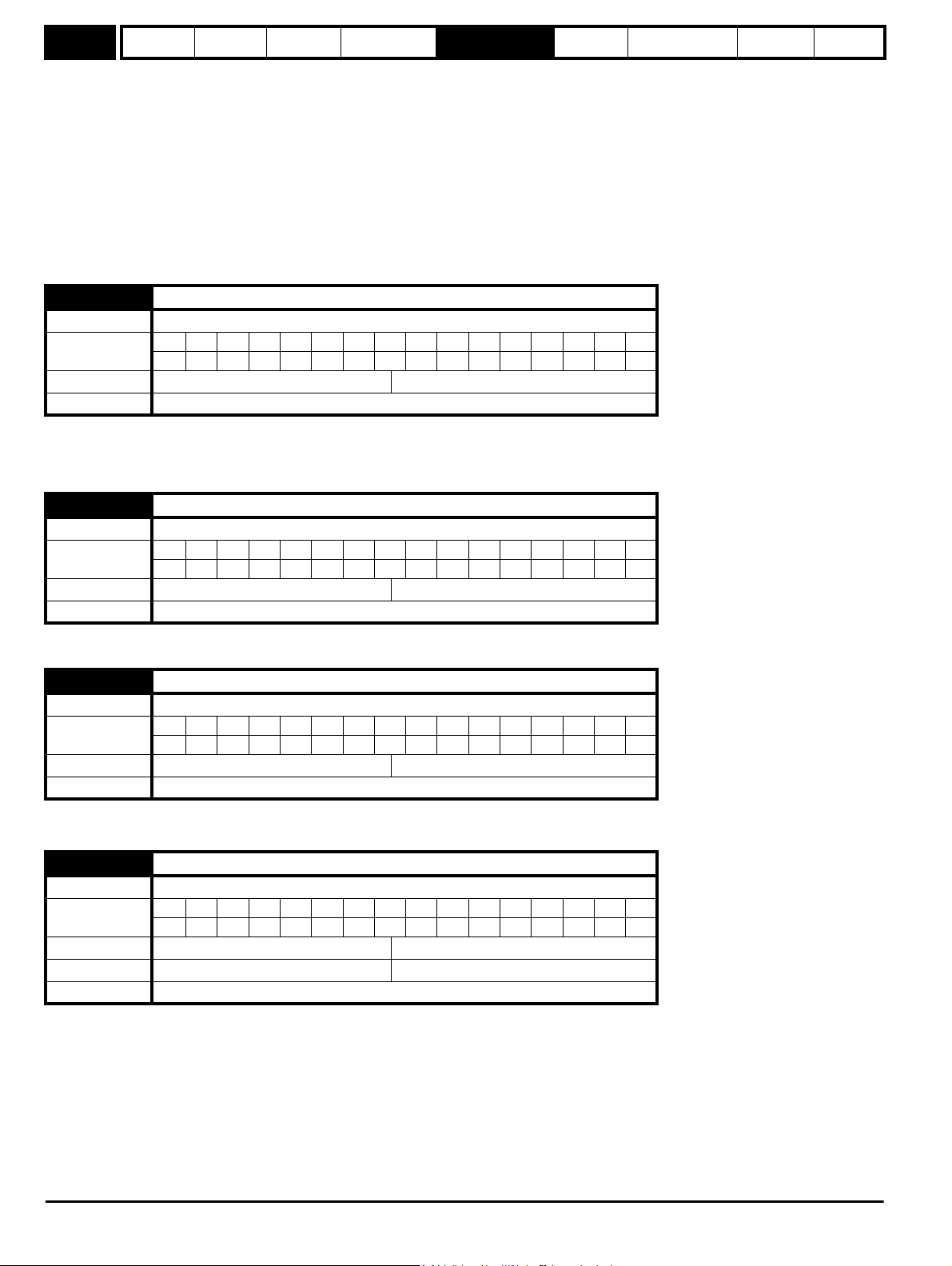
Menu 1
Parameter
structure
Keypad and
display
Parameter
x.00
Parameter
description format
Advanced parameter
descriptions
PC comms
protocol
Building automation
network
Performance RFC mode
Pr 1.41 to Pr 1.44 control Pr 1.49. The priority order is Pr 1.44 (highest), Pr 1.43, Pr 1.42, Pr 1.41 (lowest). If more than one parameter is active, the
highest priority takes precedence.
Pr 1.41 = 1 forces Pr 1.49 = 2 (see table in Pr 1.14 on page 31 and Pr 1.15 on page 32)
Pr 1.42 = 1 forces Pr 1.49 = 3 (always selects preset references)
Pr 1.43 = 1 forces Pr 1.49 = 4 (always selects keypad control mode)
Pr 1.44 = 1 forces Pr 1.49 = 5 (always selects precision reference)
Pr 1.45 to Pr 1.47 control Pr 1.50.
Pr 1.45 controls Pr 1.50 bit 0*
Pr 1.46 controls Pr 1.50 bit 1*
Pr 1.47 controls Pr 1.50 bit 2*
*See the description with Pr 1.14 and Pr 1.15 on page 32 for more information.
1.48 Reference timer reset flag
Drive modes Open-loop, RFC
Coding
Bit SP FI DE Txt VM DP ND RA NC NV PT US RW BU PS
111
Default Open-loop, RFC 0
Update rate Background read
When this flag is set, the preset timer for auto preset timer mode (Pr 01.15 = 9) is reset and preset 1 is selected. This can be used to start a new
sequence of reference selection by a programmable input terminal or function. When this bit is zero the preset selection will follow the timer even
when the drive is disabled.
1.49 Reference selected indicator
Drive modes Open-loop, RFC
Coding
Bit SP FI DE Txt VM DP ND RA NC NV PT US RW BU PS
111 1
Range Open-loop, RFC 1 to 5
Update rate 4ms write
Indicates the reference currently selected.
1.50 Preset reference selected indicator
Drive modes Open-loop, RFC
Coding
Bit SP FI DE Txt VM DP ND RA NC NV PT US RW BU PS
111 1
Range Open-loop, RFC 1 to 8
Update rate 4ms write
Indicates the preset reference currently being selected.
1.51 Power-up keypad control mode reference
Drive modes Open-loop, RFC
Coding
Bit SP FI DE Txt VM DP ND RA NC NV PT US RW BU PS
1111
Range Open-loop, RFC 0 to 2
Default Open-loop, RFC 0
Update rate N/A
Selects the value of the keypad control mode (Pr 1.17) at power-up as follows:
0 rESEt zero
1 LASt last value used before power-down
2 PrS1 Preset 1, Pr 1.21, before power-down
36 Affinity Advanced User Guide
Issue Number: 3
Page 37
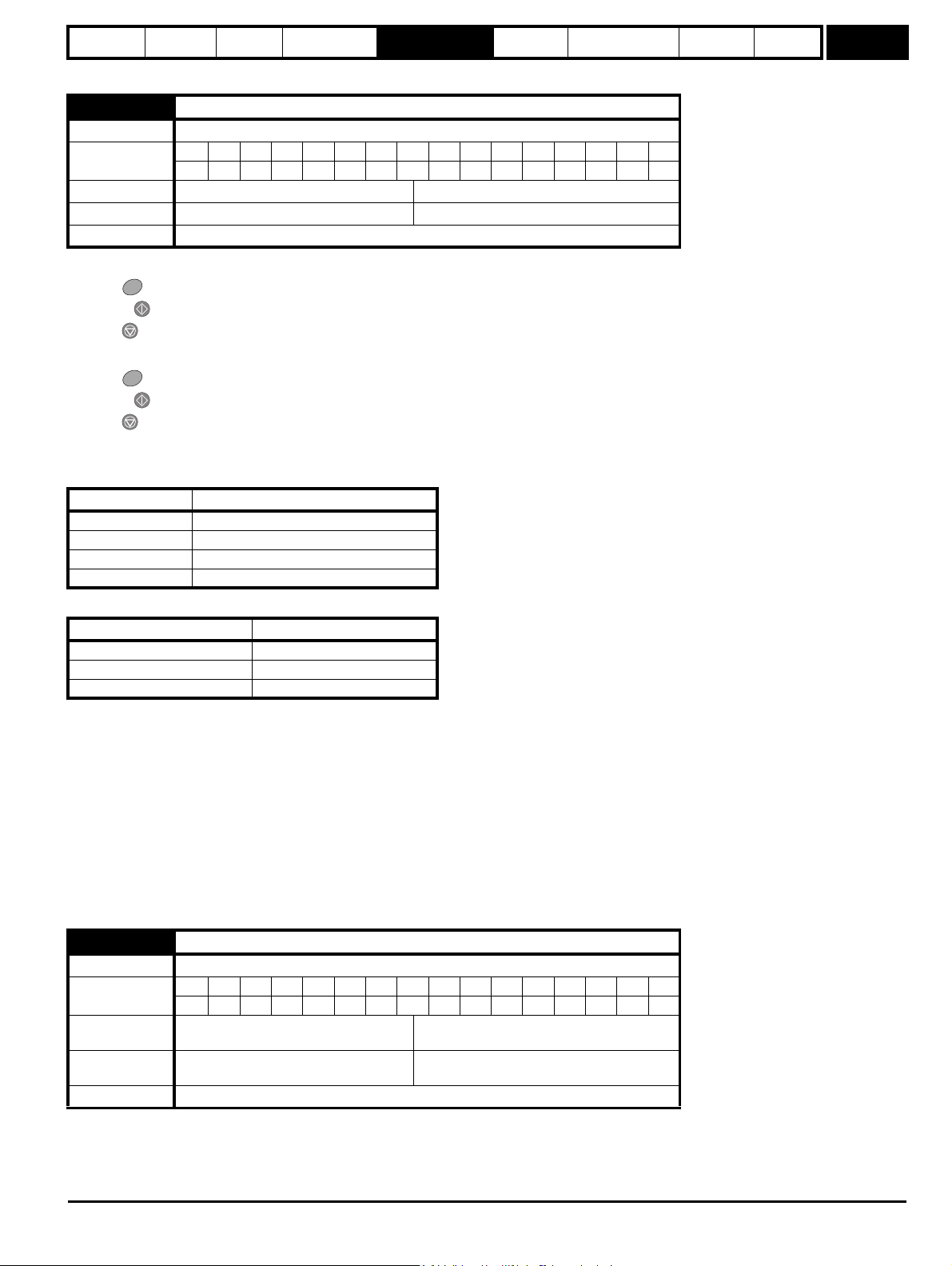
Parameter
structure
Keypad and
display
Parameter
x.00
Parameter
description format
Advanced parameter
descriptions
PC comms
protocol
Building automation
network
Performance RFC mode
5.3.1 Hand / Off / Auto
1.52 Enable hand/off/auto keypad operating mode
Drive modes Open-loop, RFC
Coding
Range Open-loop, RFC 0 to 3
Default Open-loop, RFC 1
Update rate Background read
Hand / Off / Auto functions are enabled if Pr 1.52 is set to a non-zero value, otherwise the keypad buttons are allocated as follows:
• Blue - Forward/Reverse
• Green - Run
• Red - Reset
When Hand / Off / Auto functions are enabled (Pr 1.52 set to either 1, 2 or 3), then the keypad buttons will be allocated as follows:
• Blue - Auto
• Green - Hand
• Red - Off/Reset
The value in Pr 1.52 selects Hand/Off/Auto mode on power-up as shown in Table 5-3.
Table 5-3 Hand/Off/Auto mode
Bit SP FI DE Txt VM DP ND RA NC NV PT US RW BU PS
111
Menu 1
Pr 1.52 Power up
0 Hand/Off/Auto disabled
1 Auto Mode
2 Off Mode
3 See table Table 5-4
Table 5-4 Power-up modes if Pr 1.52 = 3
Power-down Power-up
Hand Off
Off Off
Auto Auto
Auto
In Auto mode, the reference for the motor speed/frequency will be selected by the value set in Pr 0.05.
Hand
The speed/frequency reference Pr 0.05 is automatically set to keypad reference. The motor speed is determined by the value in the keypad control
mode reference Pr 1.17, which can be adjusted by pressing the Up/Down arrows on the keypad.
When Hand is selected from Auto, Pr 1.17 will be set to the value of the Pre-ramp reference (Pr 1.03) on mode transition, so the current motor speed
is maintained.
If Hand mode is selected from Off mode, the motor will ramp up to the speed determined by the value in Pr 1.17.
Off
In Off mode, the motor will be stopped. The speed/frequency reference (Pr 0.05) is automatically set to keypad reference, allowing the value in the
keypad control mode reference (Pr 1.17) to be modified by pressing the Up/Down arrow keys. If Hand mode is then subsequently selected, the motor
will ramp up to the speed determined by the value in Pr 1.17.
1.53 Fire mode reference
Drive modes Open-loop, RFC
Coding
Range Open-loop, RFC
Default
Update rate Background read
Bit SP FI DE Txt VM DP ND RA NC NV PT US RW BU PS
11 1 11
-SPEED_FREQ_MAX to
+SPEED_FREQ_MAX Hz/rpm
Open-loop
RFC
0.0Hz
0.0rpm
Affinity Advanced User Guide 37
Issue Number: 3
Page 38
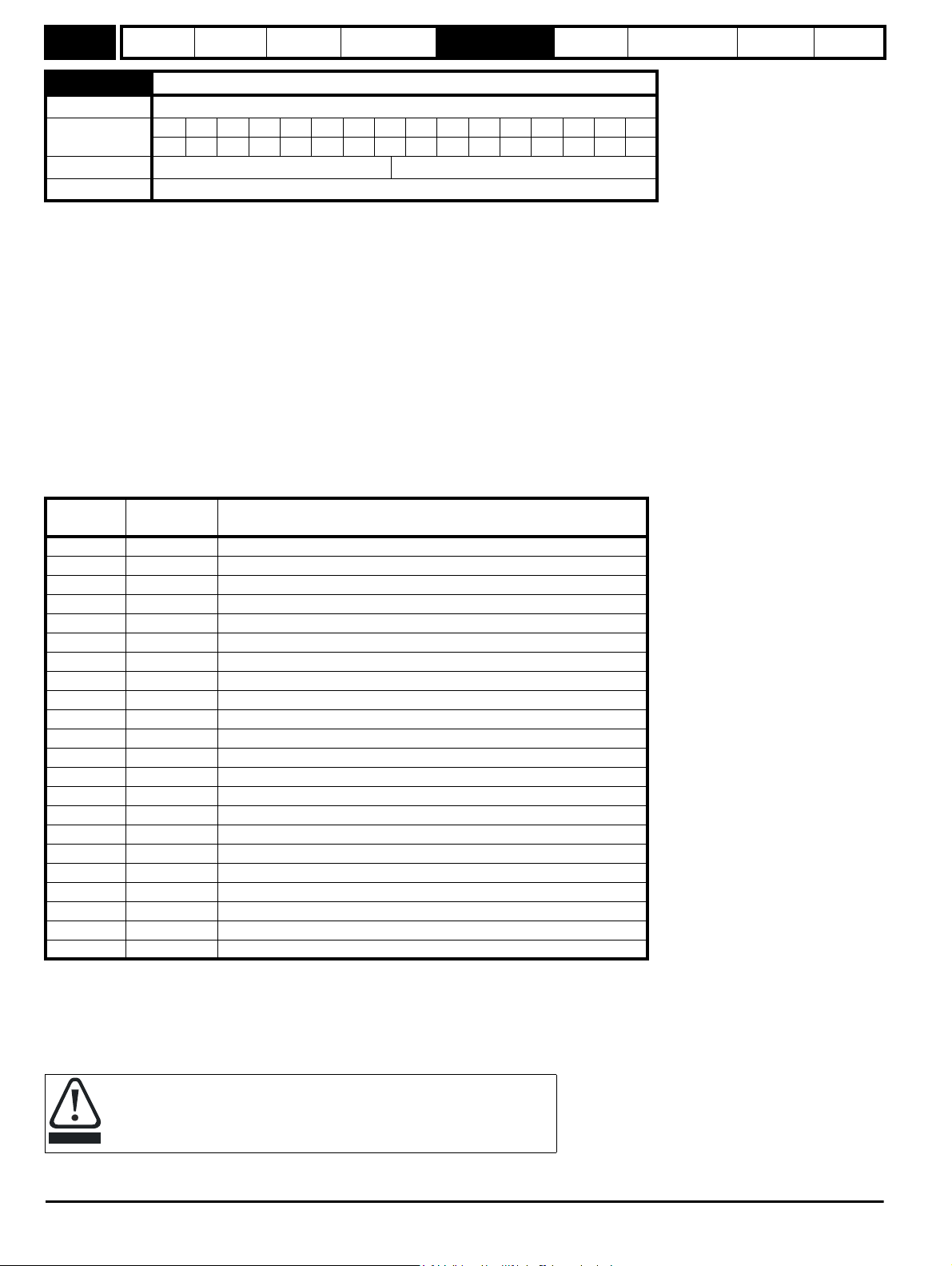
Menu 1
CAUTION
Parameter
structure
Keypad and
display
Parameter
x.00
Parameter
description format
Advanced parameter
descriptions
PC comms
protocol
Building automation
network
Performance RFC mode
1.54 Fire mode activate
Drive modes Open-loop, RFC
Coding
Bit SP FI DE Txt VM DP ND RA NC NV PT US RW BU PS
11
Default Open-loop, RFC 0
Update rate Background read
Emergency ventilation or fire mode allows for the purging of air from a structure during a fire. It is enabled if Pr 1.53 is set to a non zero value and
activated when Pr 1.54 is set to one. When activated, the pre-ramp reference (Pr 1.03) is set to the value of Pr 1.53 and the normal drive controls are
overridden as follows:
1. Drive enable is only controlled by the Enable input (Pr 6.15). The control word (Pr 6.43) cannot be used to disable the drive.
2. The internal run command is forced to be active. The normal drive sequencing bits (Pr 6.30 to Pr 6.34) and the control word have no effect.
3. The limit switch functions (Pr 6.35 and Pr 6.36) have no effect and will not stop the motor.
4. The hard speed reference is forced to zero. The hard speed reference should not be used when fire mode is likely to be activated as this will
cause an abrupt change of speed.
5. The hand/off/auto function is disabled. If this system is in the hand state when fire mode is activated it will be forced to the off state, in order that
the hand state is not active when fire mode is de-activated.
6. Keypad mode is disabled.
7. All latching mode states are reset.
If the fire mode activate parameter is subsequently set to zero the drive returns to normal operation. The fire mode activate parameter does not have
the RW attribute set, and so it must be controlled from a digital input. This prevents fire mode from being enabled via the keypad, serial comms or a
correctly functioning Solutions Modules.
If the drive is in the tripped state when fire mode is activated, the trip is reset and thereafter only the trips listed in the table below can be initiated while
fire mode is active.
Trip
number
String Cause of trip
2 OU DC bus over-voltage
3 OI.AC AC instantaneous over-current
4 OI.br Braking resistor instantaneous over current
5 PS Drive power supply fault
8 PS.10V 10V user power supply overload
9 PS.24V 24V internal power supply overload
21 O.ht1 Power device over temperature based on thermal model
31 EEF EEProm failure
36 SAVE.Er User parameter save error
37 PSAVE.Er Power down save parameter error
103 OIbr.P Power module braking IGBT over current
104 OIAC.P Power module over current detected from the module output currents
105 Oht2.P Power module heatsink over temperature
106 OU.P Power module DC bus over-voltage
107 Ph.P Power module phase loss detection
108 PS.P Power module power supply fail
109 OIdc.P Power module over current detected from on state voltage monitoring
110 Unid.P Power module unidentified trip
200 SL1.HF Slot 1 Solutions Module failure
205 SL2.HF Slot 2 Solutions Module failure
210 SL3.HF Slot 3 Solutions Module failure
217 to 232 HF17 to HF32 Hardware faults
Most of the trips included in the table are initiated in hardware and cannot be prevented in fire mode. These can be reset using the auto-reset
function. The number of reset attempts can be set to a value from 1 to 5, or set to infinite attempts - see Pr 10.34, Number of auto-reset attempts on
page 155 for details.
SLx.HF trips are allowed because these provide a watchdog function for most Solutions Modules and cannot be reset. HF17 to HF32 are hardware
related faults that will prevent the drive from operating and cannot be reset. EEF, SAVE.Er and PSAVe.Er indicate that the parameter data taken from
EEPROM is incorrect at power-up, and so the drive cannot run.
It is possible for the drive to become damaged when operating in fire mode
because some of the drive thermal protection trips are disabled.
38 Affinity Advanced User Guide
Issue Number: 3
Page 39

Parameter
structure
Keypad and
display
Parameter
x.00
Parameter
description format
Advanced parameter
descriptions
PC comms
protocol
Building automation
network
Performance RFC mode
Menu 2
Affinity Advanced User Guide 39
Issue Number: 3
Page 40

Menu 2
0 0 0
0 0 1
0 1 0
0 1 1
1 0 0
1 0 1
1 1 0
1 1 1
Acceleration rate select bits
2.11
Acceleration rate 1
2.12
Acceleration rate 2
2.13
Acceleration rate 3
2.14
Acceleration rate 4
2.15
Acceleration rate 5
2.16
Acceleration rate 6
2.17
Acceleration rate 7
2.18
Acceleration rate 8
Acceleration rates 1 ~ 8
1.50
3
4
1
2
7
5
6
Preset reference
selected indicator
2.19
Jog acceleratio n
rate
1.13
Jog selected
indicator
1.03
Pre-ramp speed
reference
2.03
Ramp hold
2.04
Ramp mode
select*
NtN
t
Acceleration
Reverse
accel. rate
Forward
accel. rate
Ramp control
2.10
Acceleration
rate selector
2.34
2.32
2.33
2.32
0.XX
0.XX
Key
Read-write (RW)
parameter
Read-only (RO)
parameter
Input
terminals
Output
terminals
The parameters are all shown at their default settings
8
Parameter
structure
Keypad and
display
Parameter
x.00
Parameter
description format
Advanced parameter
descriptions
PC comms
protocol
Building automation
network
Performance RFC mode
5.4 Menu 2: Ramps
The pre-ramp frequency or speed reference passes through the ramp block controlled by menu 2 before being used by the drive to produce the basic
output frequency (Open-loop modes), or as an input to the speed controller (RFC mode). The ramp block includes: linear ramps, an S ramp function
for ramped acceleration and deceleration, deceleration ramp control to prevent rises in the DC bus voltage within the drive that would cause an overvoltage trip if no braking resistor is installed.
Figure 5-2 Menu 2 logic diagram
40 Affinity Advanced User Guide
Issue Number: 3
Page 41

Parameter
2.06
S-Ramp enable**
2.07
S-Ramp acceleration
limit
2.08
Standard ramp voltage*
Ramp control
N
t
N
t
Deceleration
Forward
Decel. rate
Reverse
Decel. rate
+
_
2.01
Post-ramp
reference
2.02
Ramp
(RFC only)
enable
Current control
Menu 4
(Open-loop only)
Deceleration rate select bits
2.21
Deceleration rate 1
2.22
Deceleration rate 2
2.23
Deceleration rate 3
2.24
Deceleration rate 4
2.25
Deceleration rate 5
2.26
Deceleration rate 6
2.27
Deceleration rate 7
2.28
Deceleration rate 8
Deceleration rates 1 ~ 8
3
4
1
2
785
6
2.37
1.50
Preset reference
selected indicator
2.29
Jog deceleration
rate
1.13
Jog selected
indicator
2.38
Inertia compensation
torque
(RFC only)
d/dt
2.20
Deceleration
rate selector
2.36
2.35
Ramps always enabled
in Open-loop
structure
Keypad and
display
Parameter
x.00
Parameter
description format
Advanced parameter
descriptions
PC comms
protocol
Building automation
network
Performance RFC mode
Menu 2
* For more information refer to Pr 2.04 on page 42.
** For more information refer to Pr 2.06 on page 43.
Affinity Advanced User Guide 41
Issue Number: 3
Page 42

Menu 2
Parameter
structure
Keypad and
display
Parameter
x.00
Parameter
description format
Advanced parameter
descriptions
2.01 Post ramp reference
Drive modes Open-loop, RFC
Coding
Bit SP FI DE Txt VM DP ND RA NC NV PT US RW BU PS
11111
Range Open-loop, RFC ±SPEED_FREQ_MAX Hz/rpm
Update rate 4ms write
2.02 Ramp enable
Drive modes RFC
Coding
Bit SP FI DE Txt VM DP ND RA NC NV PT US RW BU PS
1111
Default RFC 1
Update rate 4ms read
2.03 Ramp hold
Drive modes Open-loop, RFC
Coding
Bit SP FI DE Txt VM DP ND RA NC NV PT US RW BU PS
111
Default Open-loop, RFC 0
Update rate 4ms read
PC comms
protocol
Building automation
network
Performance RFC mode
If this bit is set the ramp will be held. If S ramp is enabled the acceleration will ramp towards zero causing the ramp output to curve towards a constant
speed.
2.04 Ramp mode select
Drive modes Open-loop, RFC
Coding
Range
Bit SP FI DE Txt VM DP ND RA NC NV PT US RW BU PS
1111
Open-loop
RFC
0 to 2
0 to 1
Default Open-loop, RFC 1
Update rate 4ms read
This parameter does not affect the acceleration ramp, and the ramp output always rises at the programmed acceleration rate subject to the current
limits. It is possible under some unusual circumstances in open-loop mode (i.e. with highly inductive supplies), for the motor to reach a low speed in
standard ramp mode, but not completely stop. It is also possible if the drive attempts to stop the motor with an overhauling load in any mode, that the
motor will not stop when standard ramp mode or fast ramp mode is used.
If the drive is in the deceleration state, the rate of fall of the frequency or speed is monitored. If this does not fall for 10 seconds, the drive forces the
frequency or the speed reference to zero. This only applies when the drive is in the deceleration state, and not when the reference is simply set to
zero. If the speed or frequency reference is set to zero with an overhauling or very high inertia load, then the drive may not decelerate.
0: Fast ramp
Fast ramp is used where the deceleration follows the programmed deceleration rate subject to current limits.
1: Standard ramp
Standard ramp is used during deceleration if the voltage rises to the standard ramp level (Pr 2.08). It causes a controller to operate, the output of
which changes the demanded load current in the motor. As the controller regulates the DC bus voltage, the motor deceleration increases as the
speed approaches zero speed. When the motor deceleration rate reaches the programmed deceleration rate, the controller ceases to operate and
the drive continues to decelerate at the programmed rate.
If the standard ramp voltage (Pr 2.08) is set lower than the nominal DC bus level, the drive will not decelerate the motor, but it will coast to a rest. The
output of the ramp controller (when active) is a current demand that is fed to the frequency changing current controller (Open-loop mode) or the
torque producing current controller (RFC mode). The gain of these controllers can be modified with Pr 4.13 and Pr 4.14.
42 Affinity Advanced User Guide
Issue Number: 3
Page 43

Parameter
DC Bus voltage
Motor Speed
Programmed
deceleration
rate
t
Controller
operational
structure
Keypad and
display
Parameter
x.00
Parameter
description format
Advanced parameter
descriptions
PC comms
protocol
Building automation
network
Performance RFC mode
Menu 2
2: Standard ramp with motor voltage boost
This mode is the same as normal standard ramp mode except that the motor voltage is boosted by 20%. This increases the losses in the motor giving
faster deceleration.
2.06 S ramp enable
Drive modes Open-loop, RFC
Coding
Bit SP FI DE Txt VM DP ND RA NC NV PT US RW BU PS
111
Default Open-loop, RFC 0
Update rate 4ms read
Setting this parameter enables the S ramp function. S ramp is disabled during deceleration when the standard ramp voltage controller is active. When
the motor is accelerated again after decelerating in standard ramp mode, the acceleration ramp used by the S ramp function is reset to zero.
2.07 S ramp acceleration limit
Drive modes Open-loop, RFC
Bit SP FI DE Txt VM DP ND RA NC NV PT US RW BU PS
Coding
1111
RFC: DP = 3
Range
Default
Open-loop
RFC
Open-loop
RFC
0.0 to 300.0 s
0.000 to 100.000 s
3.1
1.500
2
/100Hz
2
/1,000rpm
Update rate Background read
This parameter defines the maximum rate of change of acceleration/deceleration. If the S ramp is disabled (Pr 2.06 = 0) a linear ramp is used and the
time in seconds taken for the ramp output to change by frequency (f*) or speed (w*) is given by:
Frequency (Open-loop mode)
T
f* x A / 100
Ramp =
where A is the selected ramp rate in s / 100Hz
Speed (RFC)
T
w* x A / 100
Ramp =
Where A is the selected ramp rate in s / 1000rpm
If the S ramp is enabled (Pr 2.06 = 1) then the ramp time is extended as shown in the diagram below.
Affinity Advanced User Guide 43
Issue Number: 3
Page 44

Menu 2
t
Acceleration
Actual Speed
Programmed
ramp rate
TT
T/2 T/2 T/2T/2
S ramp
acceleration
ramp
Demanded Speed
Parameter
structure
Keypad and
display
Parameter
x.00
Parameter
description format
Advanced parameter
descriptions
PC comms
protocol
Building automation
network
Performance RFC mode
The time taken in seconds for the ramp output to change by frequency (f*) or speed (w*) is given below. Two cases are given because the total
ramp time must be calculated with a different equation depending on whether the acceleration is able to reach the selected ramp rate (A) or not. If the
required change is small the selected ramp rate is not reached and the ramp does not include the central linear ramp region. If the required change is
larger, the ramp does include the central linear region as shown in the diagram above.
Frequency (Open-loop mode)
f*
= 100 x J / A
linear
where:
A is the selected ramp rate in s / 100Hz
J is parameter Pr 2.07, the S ramp acceleration limit in s
If the required change is less than f*
= 2 (f* x J / 100)
T
Ramp1
= (f* x A / 100) + (J / A)
T
Ramp2
2
2
/ 100Hz
linear
then T
should be used, but if the speed change is greater or equal to f*
Ramp1
linear TRamp2
should be used.
Speed (RFC)
w*
= 1000 x J / A
linear
where:
A is the selected ramp rate in s / 1000rpm
J is Pr 2.07, the S ramp acceleration limit in s
If the required change is less than w*
used.
T
= 2 (w* x J / 1000)
Ramp1
= (w* x A / 1000) + (J / A)
T
Ramp2
The default values for the ramp rate and S ramp acceleration limit have been chosen such that for the default maximum speed the curved parts of the
S ramp are 25% of the original ramp if S ramp is enabled. Therefore the ramp time is increased by a factor of 1.5.
2
2
/ 1000rpm
linear
then T
should be used, but if the speed change is greater or equal to w*
Ramp1
linear
T
Ramp1
should be
2.08 Standard ramp voltage
Drive modes Open-loop, RFC
Coding
Bit SP FI DE Txt VM DP ND RA NC NV PT US RW BU PS
11 111
Range Open-loop, RFC 0 to dc _VOLTAGE_SET_MAX V
200V rating drive: 375
Default Open-loop, RFC
400V rating drive: EUR: 750 / USA: 775
575V rating drive: 895
690V rating drive: 1,075
Update rate Background read
This voltage is used as the control level for standard ramp mode. If this parameter is set too low, the machine will coast to a rest, and if it is set too
high and no braking resistor is used, the drive may indicate an OU trip. The minimum level should be greater than the voltage produced on the DC
bus by the highest supply voltage. Normally the DC bus voltage will be approximately the rms supply line voltage x 2.
44 Affinity Advanced User Guide
Issue Number: 3
Page 45

Parameter
structure
Keypad and
display
Parameter
x.00
Parameter
description format
Advanced parameter
descriptions
PC comms
protocol
Building automation
network
Performance RFC mode
Menu 2
2.09 Deceleration failure detection
Drive modes Open-loop, RFC
Coding
Bit SP FI DE Txt VM DP ND RA NC NV PT US RW BU PS
111
Default Open-loop, RFC OFF (0)
Update rate Background read
Deceleration failure detection is provided to force the drive to change from the decelerating state to the appropriate stop state if the motor frequency
or speed is held at a constant level for 10s or more when the standard ramp voltage controller is active. When the drive is connected to a highly
inductive supply, it is possible for the d.c. link voltage to rise as the motor frequency/speed falls. This rise in d.c. link voltage causes the standard ramp
d.c. link voltage controller to prevent any further deceleration.
In some applications with very high inertia, the motor frequency/speed must fall very slowly or else the power fed into the d.c. link will cause an overvoltage trip. In these applications it may be necessary to disable the deceleration failure detection system by setting this parameter to 1.
2.10 Acceleration rate selector
Drive modes Open-loop, RFC
Coding
Bit SP FI DE Txt VM DP ND RA NC NV PT US RW BU PS
111
Range Open-loop, RFC 0 to 9
Default Open-loop, RFC 0
Update rate 4ms read
The acceleration rate is selected as follows.
0 Ramp rate selection by terminal input
1 - 8 Ramp rate defined by parameter number, i.e. 1 = Pr 2.11, 2 = Pr 2.12, etc.
9 Ramp rate selection by Pr 1.50
When Pr 2.10 is set to 0, the acceleration ramp rate selected depends on the state of bit Pr 2.32 to Pr 2.34. These bits are for control by digital inputs
such that ramp rates can be selected by external control. The ramp rate selected depends on the binary code generated by these bits as follows:
Pr 2.34 Pr 2.33 Pr 2.32 Ramp defined by
00 0 Pr 2.11
00 1 Pr 2.12
01 0 Pr 2.13
01 1 Pr 2.14
10 0 Pr 2.15
10 1 Pr 2.16
11 0 Pr 2.17
11 1 Pr 2.18
When Pr 2.10 is set to 9, the appropriate acceleration rate is automatically selected depending on the value of Pr 1.50, and so an acceleration rate
can be programmed to operate with each reference. Since the new ramp rate is selected with the new reference, the acceleration applies towards the
selected preset if the motor needs to accelerate to reach the preset.
Affinity Advanced User Guide 45
Issue Number: 3
Page 46

Menu 2
Parameter
structure
Keypad and
display
Parameter
x.00
Parameter
description format
Advanced parameter
descriptions
PC comms
protocol
Building automation
network
Performance RFC mode
2.11 Acceleration rate 1
2.12 Acceleration rate 2
2.13 Acceleration rate 3
2.14 Acceleration rate 4
2.15 Acceleration rate 5
2.16 Acceleration rate 6
2.17 Acceleration rate 7
2.18 Acceleration rate 8
Drive modes Open-loop, RFC
Bit SP FI DE Txt VM DP ND RA NC NV PT US RW BU PS
Coding
1111
RFC: DP = 3
Range
Default
Second motor
parameter
Open-loop
RFC
Open-loop
RFC
Open-loop, RFC Pr 21.04 for Pr 2.11 only
0.0 to 3,200.0 s/100Hz
0.000 to 3,200.000 s/1000rpm
EUR> 40.0, USA> 33.0
EUR> 13.333, USA> 11.111
Update rate 4ms read
RFC
If an acceleration rate is selected where the parameter is set to 0.000, the acceleration ramp is disabled and the reference changes instantly to its
new value during acceleration.
Open-loop
If either an acceleration or deceleration rate is selected where the parameter is set to 0.0 in open-loop mode, the ramps are disabled for both
acceleration and deceleration. This disables the voltage controller, used for standard ramp and mains loss ride through, and the frequency based
current limits.
2.19 Jog acceleration rate
Drive modes Open-loop, RFC
Bit SP FI DE Txt VM DP ND RA NC NV PT US RW BU PS
Coding
1111
RFCL: DP = 3
Range
Default
Open-loop
RFC
Open-loop
RFC
0.0 to 3200.0 s/100Hz
0.000 to 3200.000 s/1000rpm
0.2
0.000
Update rate Background read
The jog acceleration rate is only used when accelerating towards the jog reference and when changing the jog reference.
2.20 Deceleration rate selector
Drive modes Open-loop, RFC
Coding
Bit SP FI DE Txt VM DP ND RA NC NV PT US RW BU PS
111
Range Open-loop, RFC 0 to 9
Default Open-loop, RFC 0
Update rate 4ms read
The acceleration rate is selected as follows:
0 Ramp rate selection by terminal input
1 - 8 Ramp rate defined by parameter number, i.e. 1 = Pr 2.21, 2 = Pr 2.22, etc.
9 Ramp rate selection by Pr 1.50
46 Affinity Advanced User Guide
Issue Number: 3
Page 47

Parameter
structure
Keypad and
display
Parameter
x.00
Parameter
description format
Advanced parameter
descriptions
PC comms
protocol
Building automation
network
Performance RFC mode
Menu 2
When Pr 2.20 is set to 0, the deceleration ramp rate selected depends on the state of bit Pr 2.35 to Pr 2.37. These bits are for control by digital inputs
such that ramp rates can be selected by an external control. The ramp rate selected depends on the binary code generated by these bits as follows:
02.37 02.36 02.35 Ramp defined by
00 0 Pr 2.21
00 1 Pr 2.22
01 0 Pr 2.23
01 1 Pr 2.24
10 0 Pr 2.25
10 1 Pr 2.26
11 0 Pr 2.27
11 1 Pr 2.28
When Pr 2.20 is set to 9, the appropriate deceleration rate is automatically selected depending on the value of Pr 1.50, and so a deceleration rate can
be programmed to operate with each reference. Since the new ramp rate is selected with the new reference, the deceleration applies towards the
selected preset if the motor needs to decelerate to reach the preset.
2.21 Deceleration rate 1
2.22 Deceleration rate 2
2.23 Deceleration rate 3
2.24 Deceleration rate 4
2.25 Deceleration rate 5
2.26 Deceleration rate 6
2.27 Deceleration rate 7
2.28 Deceleration rate 8
Drive modes Open-loop, RFC
Bit SP FI DE Txt VM DP ND RA NC NV PT US RW BU PS
Coding
1111
RFC: DP = 3
Range
Default
Second motor
parameter
Open-loop
RFC
Open-loop
RFC
Open-loop, RFC Pr 21.05 for Pr 2.21 only
0.0 to 3,200.0 s/100Hz
0.000 to 3,200.000 s/1000rpm
EUR> 40.0, USA> 33.0
EUR> 13.333, USA> 11.111
Update rate 4ms read
RFC
If a deceleration rate is selected where the parameter is set to 0.000, the deceleration ramp is disabled and the reference changes instantly to its new
value during deceleration.
Open-loop
If either an acceleration or deceleration rate is selected where the parameter is set to 0.0 in open-loop mode, the ramps are disabled for both
acceleration and deceleration. This disables the voltage controller used for standard ramp and mains loss ride through, and the frequency based
current limits.
2.29 Jog deceleration rate
Drive modes Open-loop, RFC
Bit SP FI DE Txt VM DP ND RA NC NV PT US RW BU PS
Coding
1111
RFC: DP = 3
Range
Default
Open-loop
RFC
Open-loop
RFC
0.0 to 3,200.0 s/100Hz
0.000 to 3,200.000 s/1000rpm
0.2
0.000
Update rate Background read
The jog deceleration rate is only used when the drive is changing speed (when the jog reference has changed, or to stop from the jog reference. It is
not used to go from the jog to the run state. This prevents the fast ramps normally used with jog from being used when changing between running and
jogging.
Affinity Advanced User Guide 47
Issue Number: 3
Page 48

Menu 2
Parameter
structure
Keypad and
display
Parameter
x.00
Parameter
description format
Advanced parameter
descriptions
PC comms
protocol
Building automation
network
Performance RFC mode
2.32 Acceleration select bit 0
2.33 Acceleration select bit 1
2.34 Acceleration select bit 2
2.35 Deceleration select bit 0
2.36 Deceleration select bit 1
2.37 Deceleration select bit 2
Drive modes Open-loop, RFC
Coding
Bit SP FI DE Txt VM DP ND RA NC NV PT US RW BU PS
111
Update rate 4ms read
These bits are provided for control by logic input terminals for external ramp selection (see Pr 2.10 and Pr 2.20).
2.38 Inertia compensation torque
Drive modes RFC
Coding
Bit SP FI DE Txt VM DP ND RA NC NV PT US RW BU PS
1111
Range RFC ±1,000.0 %
Update rate 4ms write
The motor and load inertia (Pr 3.18), motor torque per amp (Pr 5.32) and the rate of change of the ramp output (Pr 2.01), are used to produce a
torque feed forward value that should accelerate or decelerate the load at the required rate. This value can be used as a feed forward term that is
added to the speed controller output if Pr 4.22 is set to one. Pr 2.38 shows the torque value as a percentage of rated active current.
48 Affinity Advanced User Guide
Issue Number: 3
Page 49

Parameter
structure
Keypad and
display
Parameter
x.00
Parameter
description format
Advanced parameter
descriptions
PC comms
protocol
Building automation
network
Performance RFC mode
Menu 3
5.5 Menu 3: Speed feedback and speed control
Menu 3 relates to different functions depending on the drive mode selected as shown in the table below. The menus for some drive modes are
significantly different, and therefore the complete menu is covered in different sections.
Drive mode section Menu 3 functions
Open-loop Frequency slaving
“Zero speed” and “at speed” detectors
RFC
Frequency/Speed accuracy and resolution
Digital reference resolution
When a preset frequency/speed is used the reference resolution is 0.1Hz or 0.1rpm. Improved resolution can be obtained by using the precision
reference (0.001Hz or 0.001rpm).
Analog reference resolution
In Open-loop modes the frequency reference controlled by an analog input has a maximum resolution of 12 bits plus sign, but this is reduced if the
window time constant/filter period for this input controller by Pr 7.26, is reduced below the default value of 4.0ms. The resolution of the frequency
reference from analog inputs 2 or 3 is 10 bits plus sign.
In RFC mode the resolution from analog input 1 is better than 16 bits plus sign provided the speed reference is routed via Pr 1.36, Pr 1.37 or Pr 3.22
in high speed update mode. The resolution from analog inputs 2 or 3 is 10 bits plus sign.
Accuracy
The absolute frequency and speed accuracy depends on the accuracy of the crystal used with the drive microprocessor. The accuracy of the crystal
is 100ppm, and so the absolute frequency/speed accuracy is 100ppm (0.01%) of the reference, when a preset speed is used. If an analog input is
used the absolute accuracy is further limited by the absolute accuracy and non-linearity of the analog input.
Speed feedback, speed controller
“Zero speed”, “at speed” and overspeed
detectors
Affinity Advanced User Guide 49
Issue Number: 3
Page 50

Menu 3
2.01
Post ramp
reference
+
_
3.05
10.03
At zero speed
indicator
Zero speed
threshold
+
_
1.07
10.04
At or below min.
speed indicator
Minimum
speed
+
_
Overspeed trip
(O.SPd)
1.06
Max.
frequency
+
_
3.06
10.05
Below at-speed
window indicator
At speed
lower limit
+
_
3.07
10.07
Above at-speed
window indicator
At speed
upper limit
+
_
10.06
At speed
indicator
+20%
5.01
Motor
frequency
+
+
Slip
compensation
Menu 5
0.XX
0.XX
Key
Read-write (RW)
parameter
Read-only (RO)
parameter
Input
terminals
Output
terminals
X
X
X
X
Menu 2
0
1
1.10
Bipolar reference
select
NOR
The parameters are all shown at their default settings
1.03
Pre ramp
reference
3.09
Absolute at-speed
detect mode
0
1
+0.5Hz
Open-loop
Parameter
structure
Keypad and
display
Parameter
x.00
Parameter descriptions: Open-loop
Figure 5-3 Menu 3 Open-loop logic diagram
Parameter
description format
Advanced parameter
descriptions
PC comms
protocol
Building automation
network
Performance RFC mode
3.05 Zero speed threshold
Drive modes Open-loop, RFC
Bit SP FI DE Txt VM DP ND RA NC NV PT US RW BU PS
Coding
Range Open-loop 0.0 to 20.0 Hz
Default Open-loop 1.0
Update rate Background read
If the post ramp reference (Pr 2.01) is at or below the level defined by this parameter in either direction, the Zero speed flag (Pr 10.03) is 1, otherwise
the flag is 0.
3.06 At speed lower limit
Drive modes Open-loop, RFC
Coding
Bit SP FI DE Txt VM DP ND RA NC NV PT US RW BU PS
1111
1111
Range Open-loop 0.0 to 3,000.0 Hz
Default Open-loop 1.0
Update rate Background read
50 Affinity Advanced User Guide
Issue Number: 3
Page 51
Parameter
structure
Keypad and
display
Parameter
x.00
Parameter
description format
Advanced parameter
descriptions
PC comms
protocol
Building automation
network
Performance RFC mode
Menu 3
Open-loop
3.07 At speed upper limit
Drive modes Open-loop, RFC
Coding
Bit SP FI DE Txt VM DP ND RA NC NV PT US RW BU PS
1111
Range Open-loop 0.0 to 3,000.0 Hz
Default Open-loop 1.0
Update rate Background read
3.09 Absolute “at speed” select
Drive modes Open-loop, RFC
Coding
Bit SP FI DE Txt VM DP ND RA NC NV PT US RW BU PS
111
Default Open-loop 0
Update rate Background read
"At speed" flag (Pr 10.06) is set if the post-ramp reference (Pr 2.01) is on the boundaries or within the at speed window. Flags Pr 10.07 and Pr 10.05
are set if the reference is above or below the window respectively.
If Pr 3.09 = 0 reference window mode is used and the "at speed" condition is true if
(|Pr 1.03| - Pr 3.06) |Pr 2.01| (|Pr 1.03| + Pr 3.07)
(If the lower limit is less than zero then zero is used as the lower limit.)
If Pr 3.09 = 1 absolute window mode is used and the "at speed" condition is true if
Pr 3.06 |Pr 2.01| Pr 3.07
The speed detector system also includes an overspeed trip in open-loop mode. The level cannot be set by the user, but the drive produces an
overspeed trip if the final frequency (Pr 5.01) exceeds 1.2 x SPEED_FREQ_MAX.
Affinity Advanced User Guide 51
Issue Number: 3
Page 52

Menu 3
+
_
3.03
Speed
error
+
_
+
_
Speed loop gains
3.04
Speed
controller
output
Menu 4
+
_
Overspeed trip
(O.SPd)
1.06
Max reference clamp
+
_
3.06
10.05
Below at-speed
window indicator
At speed
lower limit
+
_
3.07
10.07
Above at-speed
window indicator
At speed
upper limit
10.06
At speed
indicator
NOR
+
_
3.05
10.03
At zero speed
indicator
Zero speed
threshold
+
_
1.07
10.04
At or below min.
speed indicator
Minimum
speed
1.10
Bipolar reference
select
+5min
-1
+20%
1.03
Pre ramp
reference
3.09
Absolute at-speed
detect mode
Speed controller
differential
feedback gains
0.XX
0.XX
Key
Read-write
(RW)
parameter
Read-only (RO)
parameter
Input
terminals
Output
terminals
The parameters are all shown at their default settings
3.08
Overspeed threshold
3.08
>0
Speed controller
gain select
3.10
3.11
(Ki1)
(Kp1)
3.13
3.14
(Ki2)
(Kp2)
3.16
(Kd1)
(Kd2)
3.153.12
3.02
Speed feedback
2.01
Post-ramp
reference
+
+
3.23
1.11
Hard speed
reference
selector
Reference
enabled
indicator
3.01
Final speed
reference
3.22
Hard speed
reference
RFC sensorless
speed feedback
calculator
3.42
Drive encoder filter
RFC
Parameter
structure
Keypad and
display
Parameter descriptions: RFC
Figure 5-4 Menu 3 RFC logic diagram
Parameter
x.00
Parameter
description format
Advanced parameter
descriptions
PC comms
protocol
Building automation
network
Performance RFC mode
52 Affinity Advanced User Guide
Issue Number: 3
Page 53
Parameter
structure
Keypad and
display
Parameter
x.00
Parameter
description format
Advanced parameter
descriptions
PC comms
protocol
Building automation
network
Performance RFC mode
Menu 3
RFC
3.01 Final speed reference
Drive modes RFC
Coding
Bit SP FI DE Txt VM DP ND RA NC NV PT US RW BU PS
1 11111
Range RFC ±SPEED_MAX rpm
Update rate 4ms write
This is the final speed demand at the input to the speed regulator formed by the sum of the ramp output and the hard speed reference (if the hard
speed reference is enabled). If the drive is disabled this parameter will show 0.0.
3.02 Speed Feedback
Drive modes RFC
Coding
Bit SP FI DE Txt VM DP ND RA NC NV PT US RW BU PS
1 11111
Range RFC ±SPEED_MAX rpm
Update rate 4ms write
The speed feedback is derived from the sensorless feedback calculation.
3.03 Speed error
Drive modes RFC
Coding
Bit SP FI DE Txt VM DP ND RA NC NV PT US RW BU PS
1 11111
Range RFC ±SPEED_MAX rpm
Update rate 4ms write
The speed error is the difference between the final speed demand and the speed feedback in rpm. This does not include the effect of the D term in the
speed controller feedback branch.
3.04 Speed controller output
Drive modes RFC
Coding
Bit SP FI DE Txt VM DP ND RA NC NV PT US RW BU PS
1 11111
Range RFC ±TORQUE_PROD_CURRENT_MAX %
Update rate 4ms write
The output of the speed regulator is a torque demand given as a percentage of rated motor torque. This is then modified to account for changes in
motor flux if field weakening is active, and then used as the torque producing current reference.
3.05 Zero speed threshold
Drive modes Open-loop, RFC
Coding
Bit SP FI DE Txt VM DP ND RA NC NV PT US RW BU PS
111
Range RFC 0 to 200 rpm
Default RFC 5
Update rate Background read
If the speed feedback (Pr 3.02) is at or below the level defined by this parameter in either direction the Zero speed flag (Pr 10.03) is 1, otherwise the
flag is 0.
3.06 At speed lower limit
Drive modes Open-loop, RFC
Coding
Bit SP FI DE Txt VM DP ND RA NC NV PT US RW BU PS
111
Range RFC 0 to 40,000 rpm
Default RFC 50
Update rate Background read
Affinity Advanced User Guide 53
Issue Number: 3
Page 54
Menu 3
RFC
Parameter
structure
Keypad and
display
Parameter
x.00
Parameter
description format
Advanced parameter
descriptions
PC comms
protocol
Building automation
network
Performance RFC mode
3.07 At speed upper limit
Drive modes Open-loop, RFC
Coding
Bit SP FI DE Txt VM DP ND RA NC NV PT US RW BU PS
111
Range RFC 0 to 40,000 rpm
Default RFC 50
Update rate Background read
"At speed" flag (Pr 10.06) is set if the speed feedback (Pr 3.02) is on the boundaries or within the at speed window. Flags Pr 10.07 and Pr 10.05 are
set if the reference is above or below the window respectively.
If Pr 3.09 = 0 reference window mode is used and the "at speed" condition is true if
(|Pr 1.03| - Pr 3.06) |Pr 3.02| (|Pr 1.03| + Pr 3.07)
(If the lower limit is less than zero then zero is used as the lower limit.)
If Pr 3.09 = 1 absolute window mode is used and the "at speed" condition is true if
Pr 3.06 |Pr 3.02| Pr 3.07
3.08 Overspeed threshold
Drive modes RFC
Coding
Bit SP FI DE Txt VM DP ND RA NC NV PT US RW BU PS
111
Range RFC 0 to 40,0000 rpm
Default RFC 0
Update rate Background read
If the speed feedback (Pr 3.02) exceeds this level in either direction an overspeed trip is produced. If this parameter is set to zero the overspeed
threshold is automatically set to 1.2 x SPEED_FREQ_MAX.
3.09 Absolute “at speed” detect
Drive modes Open-loop, RFC
Coding
Bit SP FI DE Txt VM DP ND RA NC NV PT US RW BU PS
111
Default RFC 0
Update rate Background read
See Pr 3.06 and Pr 3.07 on page 54.
3.10
3.13
Speed controller proportional gain (Kp1)
Speed controller proportional gain (Kp2)
Drive modes RFC
Coding
Range RFC
Bit SP FI DE Txt VM DP ND RA NC NV PT US RW BU PS
4111
0.0000 to 6.5335 (1/ rad s
Default RFC 0.0300
Second motor
parameter
RFC Pr 21.17
Update rate Background read
-1
)
54 Affinity Advanced User Guide
Issue Number: 3
Page 55

Parameter
Kp
Ki
Kd
Spee d
reference
(wr*)
Spee d
feedback
(wr)
To rq u e
reference
(Te*)
-
+
+
+
+
+
structure
Keypad and
display
Parameter
x.00
Parameter
description format
Advanced parameter
descriptions
PC comms
protocol
Building automation
network
Performance RFC mode
Menu 3
RFC
3.11
3.14
Speed controller integral gain (Ki1)
Speed controller integral gain (Ki2)
Drive modes RFC
Coding
Range RFC
Bit SP FI DE Txt VM DP ND RA NC NV PT US RW BU PS
2 111
0.00 to 653.35 s/rad s
Default RFC 0.10
Second motor
parameter
RFC Pr 21.18
Update rate Background read
3.12
3.15
Speed controller differential feedback gain (Kd1)
Speed controller differential feedback gain (Kd2)
Drive modes RFC
Coding
Range RFC
Bit SP FI DE Txt VM DP ND RA NC NV PT US RW BU PS
5 111
0.00000 to 0.65335 s
Default RFC 0.00000
Second motor
parameter
RFC Pr 21.19
Update rate Background read
-1
-1
/rad s
-1
3.16
Speed controller gain select
Drive modes RFC
Coding
Bit SP FI DE Txt VM DP ND RA NC NV PT US RW BU PS
111
Default RFC 0
Update rate 4ms read
The following diagram shows a generalized representation of the speed controller. The controller includes proportional (Kp) and integral (Ki) feedforward terms, and a differential (Kd) feedback term. The drive holds two sets of these gains, and either set may be selected for use by the speed
controller with Pr 3.16. If Pr 3.16 = 0, gains Kp1, Ki1 and Kd1 are used, if Pr 3.16 = 1, gains Kp2, Ki2 and Kd2 are used. Pr 3.16 may be changed
when the drive is enabled or disabled.
Proportional gain (Kp)
If Kp has a value and Ki is set to zero the controller will only have a proportional term, and there must be a speed error to produce a torque reference.
Therefore as the motor load increases there will be a difference between the reference and actual speeds. This effect, called regulation, depends on
the level of the proportional gain, the higher the gain the smaller the speed error for a given load.
Affinity Advanced User Guide 55
Issue Number: 3
Page 56

Menu 3
Kp
Ki 1/s
Kc
Kt
L(s)
+
_
+
+
w*(s)
rads
-1
w(s)
Speed controller
Ki.Kd
_
rads
-1
Kp+Ki/s
Ki.Kd
Kc.Kt L(s)
+
_
+
_
w*(s)
w(s)
T
delay
RFC
Parameter
structure
Keypad and
display
Parameter
x.00
Parameter
description format
Advanced parameter
descriptions
PC comms
protocol
Building automation
network
Performance RFC mode
Integral gain (Ki)
The integral gain is provided to prevent speed regulation. The error is accumulated over a period of time, and used to produce the necessary torque
demand without any speed error. Increasing the integral gain reduces the time taken for the speed to reach the correct level, and increases the
stiffness of the system, i.e. it reduces the positional displacement produced by applying a load torque to the motor. Unfortunately, increasing the
integral gain also reduces the system damping giving overshoot after a transient.
For a given integral gain, the damping can be improved by increasing the proportional gain. A compromise must be reached where the system
response, stiffness and damping are all adequate for the application. The integral term is implemented in the form of (Ki x error), and so the integral
gain can be changed when the controller is active without causing large torque demand transients.
Differential gain (Kd)
The differential gain is provided in the feedback of the speed controller to give additional damping. The differential term is implemented in a way that
does not introduce excessive noise normally associated with this type of function. Increasing the differential term reduces the overshoot produced by
under-damping however, for most applications the proportional and integral gains alone are sufficient. It should be noted that the differential term is
limited internally so that it is ineffective if speed in rpm x Kd x Ki is greater than 170.
To analyze the performance of the speed controller it may be represented as an s-domain model as shown below.
Where:
Kc is the conversion between the speed controller output and the torque producing current. A value of unity at the output of the speed controller gives
a torque producing current equal to Kc. The drive automatically compensates the torque producing current for flux variations in field weakening, and
so Kc can be assumed to have a constant value even in field weakening. See menu 4 for the value of Kc each drive size).
Kt is the torque constant of the motor (i.e. torque in Nm per amp of torque producing current). This value is normally available for a servo motor from
the manufacturer, however for induction motors the value must be calculated from:-
Kt = Motor rated torque / Motor rated torque producing current
= Motor rated torque / (Motor rated current
2
- No load current2)
L(s) is the transfer function of the load.
The s-domain system above may be used to determine the performance of systems with a relatively low bandwidth. However, the real drive system
also includes non-ideal delays due to the torque controller response, speed measurement and control delays. These delays, which can be
approximated with a simple unity gain transport delay (T
) as shown below, should be taken into account for more accurate results.
delay
The speed controller gains used in previous Unidrive products were in internal drive units. Conversion between the previous internal units and the SI
units used in this product are given in the table below.
Gain Conversion from previous internal units to new SI units
Kp Kp_old / 17103
Ki Ki_old / 94.41
Kd Kd_old / 46376
56 Affinity Advanced User Guide
Issue Number: 3
Page 57
Parameter
structure
Keypad and
display
Parameter
x.00
Parameter
description format
Advanced parameter
descriptions
PC comms
protocol
Building automation
network
Performance RFC mode
Menu 3
RFC
3.17
Speed controller set-up method
Drive modes RFC
Coding
Bit SP FI DE Txt VM DP ND RA NC NV PT US RW BU PS
111
Range RFC 0 to 3
Default RFC 0
Update rate Background (1s) read
The user may enter the required speed controller gains into Pr 3.10 to Pr 3.15. However, if the load is predominantly a constant inertia and constant
torque, the drive can calculate the required Kp and Ki gains, provided a value of motor plus load inertia (Pr 3.18) and the motor torque per amp
(Pr 5.32) are set-up correctly. The gain values are calculated to give a required compliance angle or bandwidth. The calculated values for Kp and Ki
are written to Pr 3.10 and Pr 3.11 once per second when one of these set-up methods is selected (i.e. Pr 3.17 = 1 or 2). The values are calculated
from a linear model assuming a pure inertia load, not including unwanted delays in the speed and current controllers. The Kd gain is not affected. If
Pr 3.17 is set to 3 automatic gain set up is not active, but Kp is boosted by a factor of 16.
0: user set-up
With the default value the user should enter the required speed controller gains.
1: Bandwidth set-up
If bandwidth based set-up is required, the following parameters must be set correctly: Pr 3.20 = required bandwidth, Pr 3.21 = required damping
factor, Pr 3.18 = motor + load inertia (it is possible to measure the load inertia as part of the auto-tuning process, see Pr 5.12 on page 84), Pr 5.32 =
motor torque per amp.
Ki = J / (Kc x Kt) x (2 x Bandwidth / Kbw)
2
= Pr 3.18 / (Kc x Pr 5.32) x (2 x Pr 3.20 / Kbw)
2
Where: Kbw = [ (22 + 1) +((22 + 1)2 + 1) ]
Kp = 2 [(Ki x J) / (Kc x Kt)] = 2 [(Pr 3.11 x Pr 3.18) / (Kc x Pr 5.32)]
2: Compliance angle set-up
If compliance angle based set-up is required the following parameters must be set correctly: Pr 3.19 = required compliance angle, Pr 3.21 = required
damping factor, Pr 3.18 = motor + load inertia (it is possible to measure the load inertia as part of the auto-tuning process, see Pr 5.12 on page 84),
Pr 5.32 = motor torque per amp.
Ki = 1 / Compliance angle (rad s
-1
)
Kp = 2 [(Ki x J) / (Kc x Kt)] = 2 [(Pr 3.11 x Pr 3.18) / (Kc x Pr 5.32)]
3: Kp gain times 16
If this parameter is set to 3, the Kp gain (from whichever source) is multiplied by 16. This is intended to boost the range of Kp for applications with very
high inertia. It should be noted that if high values of Kp are used, it is likely that the speed controller output will need to be filtered (see Pr 4.12), or the
speed feedback will need to be filtered (see Pr 3.42). If the feedback is not filtered, it is possible the output of the speed controller will be a square
wave which changes between the current limits causing the integral term saturation system to malfunction.
3.18
Motor and load inertia
Drive modes RFC
Coding
Range RFC
Bit SP FI DE Txt VM DP ND RA NC NV PT US RW BU PS
5 111
0.00000 to 90.00000 kg m
2
Default RFC 0.00000
Update rate Background (1s) read
The motor and load inertia represents the total inertia driven by the motor. This is used to set the speed controller gains (see Pr 3.13 on page 54) and
to provide torque feed-forwards during acceleration when required. (see Pr 4.11 on page 69) (It is possible to measure the inertia as part of the autotune process, see Pr 5.12 on page 84.
3.19
Compliance angle
Drive modes RFC
Coding
Bit SP FI DE Txt VM DP ND RA NC NV PT US RW BU PS
1 111
Range RFC 0.0 to 359.9 °mechanical
Default RFC 4.0
Update rate Background (1s) read
The compliance angle is the required angular displacement when the drive delivers a torque producing current equivalent to the current scaling (Kc)
with no field weakening.
Affinity Advanced User Guide 57
Issue Number: 3
Page 58

Menu 3
RFC
Parameter
structure
Keypad and
display
Parameter
x.00
Parameter
description format
Advanced parameter
descriptions
PC comms
protocol
Building automation
network
Performance RFC mode
3.20
Bandwidth
Drive modes RFC
Coding
Bit SP FI DE Txt VM DP ND RA NC NV PT US RW BU PS
111
Range RFC 0 to 255 Hz
Default RFC 10 Hz
Update rate Background (1s) read
The bandwidth is defined as the theoretical 3dB point on the closed-loop gain characteristic of the speed controller as a second order system. At this
point the phase shift is approximately 60°. This parameter is used to define the bandwidth used for setting up the speed loop gain parameters
automatically when Pr 3.17 = 1.
3.21
Damping factor
Drive modes RFC
Coding
Bit SP FI DE Txt VM DP ND RA NC NV PT US RW BU PS
1111
Range RFC 0.0 to 10.0
Default RFC 1.0
Update rate Background (1s) read
This is the damping factor related to the response of the system to a torque transient, and so if the damping factor is unity the response to a load
torque transient is critically damped. The step response of the speed controller gives approximately 10% overshoot with unity damping factor.
This parameter is used to define the damping factor used for setting up the speed loop gain parameters automatically when Pr 3.17 = 1 or 2.
3.22
Hard speed reference
Drive modes RFC
Coding
Bit SP FI DE Txt VM DP ND RA NC NV PT US RW BU PS
11 111
Range RFC ±SPEED_FREQ_MAX rpm
Default RFC 0.0
Update rate 4ms read
3.23
Hard speed reference selector
Drive modes RFC
Coding
Bit SP FI DE Txt VM DP ND RA NC NV PT US RW BU PS
111
Default RFC 1
Update rate 4ms read
The hard speed reference is a reference value which does not pass through the ramp system (Menu 2). It is added to the normal post ramp speed
reference. Its value may be written from the keypad, via serial comms or from an analog input.
The hard speed reference is selected when Pr 3.23 = 1.
3.24
Closed-loop vector mode
Drive modes RFC
Coding
Bit SP FI DE Txt VM DP ND RA NC NV PT US RW BU PS
111
Range RFC 3
Default RFC 3
Update rate Background read
Pr 3.24 can only be set to 3 (RFC mode) - Closed loop vector without position feedback with no maximum limit.
A filter with a 4ms time constant/filter is automatically included in the speed feedback, as this is required for this system to operate correctly.
Particularly when operating above rated speed it may be necessary to include further filtering (Pr 4.12 set to a value between 1.0 and 5.0ms) to
achieve stable operation.
58 Affinity Advanced User Guide
Issue Number: 3
Page 59

Parameter
structure
Keypad and
display
Parameter
x.00
Parameter
description format
Advanced parameter
descriptions
PC comms
protocol
Building automation
network
Performance RFC mode
Menu 3
RFC
3.42
Drive encoder filter
Drive modes RFC
Coding
Bit SP FI DE Txt VM DP ND RA NC NV PT US RW BU PS
111
Range RFC 0 to 5 (0 to16 ms)
Default RFC 0
Update rate Background read
0 = 0ms, 1 = 1ms, 2 = 2ms, 3 = 4ms, 4 = 8ms, 5 = 16ms
A sliding window filter may be applied to the feedback taken from the drive encoder. This is particularly useful in applications where the drive encoder
is used to give speed feedback for the speed controller, and where the load includes a high inertia and hence the speed controller gains are very high.
Under these conditions without a filter on the feedback, it is possible for the speed loop output to change constantly from one current limit to the other
and lock the integral term of the speed controller.
This parameter also defines a filter on the output of the speed estimator which is used as the speed feedback. A filter with a 4ms time constant/filter is
always present on the output of the speed estimator, but this filter may be extended as follows: 0 = 4ms, 1 = 8ms, 2 = 16ms, 3 = 32ms, 4 = 64ms, 5 =
128ms. The output of the speed estimator can include some ripple, which increases as the drive passes into field weakening, and the filter can be
used to remove this ripple. This is particularly useful when using standard ramp or spinning start with a low friction high inertia load, and can prevent
over voltage trips when the drive has no braking resistor.
Affinity Advanced User Guide 59
Issue Number: 3
Page 60

Menu 4
Parameter
structure
Keypad and
display
Parameter
x.00
Parameter
description format
Advanced parameter
descriptions
PC comms
protocol
Building automation
network
Performance RFC mode
5.6 Menu 4: Torque and current control
The scaling of the current feedback is based on the rating of the drive as follows:
Level x Rated drive current
Over-current trip 1/0.45 = 2.22
Open-loop peak limit 1.75
RFC 1.75
Open-loop maximum standard operating current 1.5
Current scaling (Kc) 1.0
Maximum Normal Duty current rating 1.36*
Maximum motor rated current 1.36*
Current scaling (Kc) is 1 per unit current and is related to the scaling of the drive current feedback. For most drive sizes, Kc is the same as the drive
current scaling defined by Pr 11.3 2. The drive current scaling is the maximum value of rated motor current (defined by Pr 5.07 or Pr 21.07) that can be
set for operation with the force vented motor protection characteristic - Pr 4.25 = 0 (see Pr 4.16 for more details). If the Kc and drive current scaling
are the same, then the drive uses 1.75 x Drive current scaling for the open-loop peak limit and the maximum standard operating current for closedloop modes. This is the limit up to which the drive can control current normally. The current range above this is allowed for current controller overshoot
and for additional current feedback pulses associated with long cable operation. For some drive sizes the drive current scaling is larger than Kc,
therefore the potential overload is reduced below 1.75 x Kc.
The motor rated current (defined by Pr 5.07 or Pr 21.07), may be increased above the drive current scaling up to the maximum Normal Duty rated
current. When the motor rated current is above the drive current scaling, the drive always provides a motor protection scheme that is intended for
variable torque applications (see Pr 4.16 on page 72 for more details). The maximum rated current is the maximum rated current allowed for Normal
Duty operation.
Table below gives the current scaling (Kc), Drive current scaling and Maximum normal duty rated current for all drive sizes and voltage ratings.
Table 5-5 Current ratings
200V 400V 575V 690V
Model
BA1201 4.3 4.3 5.2 BA1401 2.1 2.1 2.8 BA3501 4.1 4.1 5.4 BA4601 18 18 22
BA1202 5.8 5.8 6.8 BA1402 3.0 3.0 3.8 BA3502 5.4 5.4 6.1 BA4602 22 22 27
BA1203 7.5 7.5 9.6 BA1403 4.2 4.2 5.0 BA3503 6.1 6.1 8.4 BA4603 27 27 36
BA1204 10.6 10.6 11 BA1404 5.8 5.8 6.9 BA3504 9.5 9.5 11 BA4604 36 36 43
BA2201 12.6 12.6 15.5 BA1405 7.6 7.6 8.8 BA3505 12 12 16 BA4605 43 43 52
BA2202 17 17 22 BA1406 9.5 9.5 11 BA3506 18 18 22 BA4606 52 52 62
BA2203 25 25 28 BA2401 13 13 15.3 BA3507 22 22 27 BA5601 62 62 84
BA3201 31 31 42 BA2402 16.5 16.5 21
BA3202 42 42 54 BA2403 23 25 29
BA4201 56 56 68 BA3401 32 32 35 BA6602 107.1 125 144
BA4202 68 68 80 BA3402 40 40 43 BAMA16X1 85.7 100 125
BA4203 80 80 104 BA3403 46 46 56 BAMA16X1 107.1 125 144
BA5201 105 105 130 BA4401 60 60 68
BA5202 130 130 154 BA4402 74 74 83
BAMD12X1 133.7 156 192 BA4403 96 96 104
BAMD12X2 164.5 192 248 BA5401 124 124 138
BAMD12X3 214.2 250 312 BA5402 156 156 168
BAMD12X4 248.5 290 350 BA6401 154.2 180 205
Current
scaling
(Kc)
Drive
current
scaling
Max
Normal
Duty
rated
current
Model
BA6402 180 210 236
BAMA14X1 154.2 180 202
BAMA14X2 180.0 210 236
BAMD14X1 154.2 180 202
BAMD14X2 180.0 210 246
BAMD14X3 205.7 246 290
BAMD14X4 248.5 290 330
Current
scaling
(Kc)
Drive
current
scaling
Max
Normal
Duty
rated
current
Model
Current
scaling
(Kc)
Drive
current
scaling
Max
Normal
Duty
rated
current
Model
BA5602 84 84 99
BA6601 85.7 100 125
BAMD16X1 85.7 100 125
BAMD16X1 107.1 125 144
BAMD16X1 123.4 144 168
BAMD16X1 144.0 168 192
Current
scaling
(Kc)
Drive
current
scaling
Max
Normal
Duty
rated
current
60 Affinity Advanced User Guide
Issue Number: 3
Page 61

Parameter
v*
Stator flux
(in steady state)
Open-loop
mode
cos (PF)
-1
Ri
ssx
Ri
ssy
i
sy
MOTOR1_CURRENT_LIMIT_MAX
Maximum current
Motor rated current
-------------------------------------------------------
2
PF21–+
PF
------------------------------------------------------------ --------------------------------------------
100%=
structure
Keypad and
display
Parameter
x.00
Parameter
description format
Advanced parameter
descriptions
PC comms
protocol
Building automation
network
Performance RFC mode
Menu 4
BAMAxxxx and BAMDxxxx drive modules can be connected in parallel provided all power modules have the same voltage and current rating to make
a larger drive. The currents are then defined as follows:
Current scaling (Kc)
Kc is the sum of Kc for all the modules.
Maximum drive current scaling
Maximum drive current scaling = 0.95 x Sum of maximum drive current scaling for all the modules.
Maximum rated current
Maximum rated current = 0.95 x Sum of maximum normal duty rated current for all the modules.
5.6.1 Open-loop
In this mode the drive operates in the stator flux reference frame under steady state conditions. The absolute maximum controlled motor current is
defined by the peak limit system as 1.75 x Kc. However, the drive does not normally operate at this level, but uses the peak limit system as protection
against over-current trips. Under normal operation the motor current is limited to 1.50 x Kc, allowing a safety margin between the maximum normal
operating current and the peak limit level. Therefore a motor with the same current rating as the drive can produce at least 150% torque when the
drive operates in current limit.
DRIVE_CURRENT_MAX is full scale current feedback, i.e. Kc / 0.45.
The relationship between the voltage and current for open-loop operation is shown in the following vector diagram.
Definitions:
vs = motor terminal voltage vector
= motor current vector
i
s
i
= y axis component of current
sy
i
= x axis component of current
sx
v* = no load y axis voltage reference
MOTOR1_CURRENT_LIMIT_MAX is used as the maximum for some parameters such as the user current limits. This is defined in the vector
diagram as follows (with a maximum of 1000%):
Where
Motor rated current is given by Pr 5.07
PF is motor rated power factor given by Pr 5.10
(MOTOR2_CURRENT_LIMIT_MAX is calculated from the motor map 2 parameters)
The Maximum current is either (1.5 x Kc) when the rated current set by Pr 5.07 (or Pr 21.07 if motor map 2 is selected) is less than or equal to the
Drive currentscaling, otherwise it is (1.1 x Maximum motor rated current).
For example, with a motor of the same rating as the drive and a power factor of 0.85, the maximum current limit is 113.6%.
The above calculation is based on the assumption that the flux producing current (Pr 4.17) in the stator flux reference frame does not vary with the
load, and remains at the level for rated load. This is not the case, and the flux producing current will vary as the load is increased. Therefore the
maximum current limit may not be reached before the drive reduces the current limit to prevent the peak limit from becoming active.
Affinity Advanced User Guide 61
Issue Number: 3
Page 62

Menu 4
Rotor flux
RFC mode
cos (PF)
-1
Ri
ssx
i
sy
1
2
i
sx
Ri
ssy
WLi
mr s s y
WLi
(steady
state)
mr s sx
v
s
i
s
MOTOR1_CURRENT_LIMIT_MAX
Maximum current
Motor rated current
-------------------------------------------------------
2
cos(
1
2
1–+
cos
1
--------------------------------------------------------------- -------------------------------------------------
100%=
2-tan
1
RsI
sxR
2 fRLsI
syR
–
V
R
-----------------------------------------------------------
=
Parameter
structure
Keypad and
display
Parameter
x.00
Parameter
description format
Advanced parameter
descriptions
PC comms
protocol
Building automation
network
Performance RFC mode
The rated active and rated magnetising currents are calculated from the power factor (Pr 5.10) and motor rated current (Pr 5.07) as:
rated active current = power factor x motor rated current
2
rated magnetising current = (1 - power factor
) x motor rated current
In this mode of operation the drive only requires the motor rated current and the power factor at rated load to set up the maximum current limits, scale
the current limits correctly and calculate the rated active and magnetizing currents. The user may enter the nameplate values in Pr 5.07 and Pr 5.10
respectively, and the drive will operate satisfactorily. Alternatively the drive can perform an auto-tune test on the motor to measure the power factor at
rated load by measuring Rs (stationary test), L
(stationary test), and Ls (rotating test). See Pr 5.12 on page 84 for details.
s
5.6.2 RFC
In this mode the drive operates in the Rotor Flux Reference frame. The maximum normal operating current is controlled by the current limits.
DRIVE_CURRENT_MAX is full scale current feedback, i.e. Kc / 0.45.
The relationship between the voltage and current for RFC operation is shown in the following vector diagram.
Definitions:
vs = motor terminal voltage vector
= motor current vector
i
s
i
= y axis component of current
sy
i
= x axis component of current
sx
MOTOR1_CURRENT_LIMIT_MAX is used as the maximum for some parameters such as the user current limits. The magnetizing current (isx)
remains constant except in field weakening where it is reduced to control the motor voltage. The maximum current limit is defined as follows (with a
maximum of 1000%):
Where:
Motor rated current is given by Pr 5.07
PF is motor rated power factor given by Pr 5.10
(MOTOR2_CURRENT_LIMIT_MAX is calculated from the motor map 2 parameters)
The Maximum current is either (1.75 x Kc) when the rated current set by Pr 5.07 (or Pr 21.07 if motor map 2 is selected) is less than or equal to
the drive current scaling, otherwise it is (1.1 x Maximum rated current).
can be derived directly by the drive auto-tune. However, if the auto-tune is not carried out 1 is derived from
1
noted that the drive autotune would make the total y axis voltage under rated load conditions equal to the rated voltage (V
the following equation.
62 Affinity Advanced User Guide
-1
= cos
1
(PF) -
2
and the power factor. It should be
2
Issue Number: 3
), therefore 2 is given by
R
Page 63

Parameter
structure
Keypad and
display
Parameter
x.00
Parameter
description format
Advanced parameter
descriptions
PC comms
protocol
Building automation
network
Performance RFC mode
Menu 4
Where:
is the motor stator resistance (Pr 5.17)
R
s
is the rated frequency (Pr 5.06)
f
R
is the transient inductance (H) (Pr 5.24 / 1000)
L
s
V
is the rated voltage (Pr 5.09)
R
I
sxR
I
sxR
and I
and I
are the currents in the x and y axes of the Rotor Flux Reference frame under rated load
syR
are derived as I
syR
= Pr 5.07 x (1 - Pr 5.102) and I
sxR
= Pr 5.07 x Pr 5.10 for the purposes of calculating
syR
. This calculation gives a
2
result that is reasonably accurate for most purposes.
rated active current = cos(
rated magnetising current = (1 - cos(
) x motor rated current
1
)2) x motor rated current
1
In this mode of operation the drive requires the following parameters to set the maximum current limits, scale the current limits correctly and calculate
the rated active and magnetising currents.
Parameters Current limit accuracy
Motor rated current, power factor at rated load
(R
and Ls are zero)
s
Motor rated current, power factor at rated load,
measured values of R
and L
s
s
Motor rated current, power factor at rated load,
measured values of R
, Ls and L
s
s
Exact current limits based on all measured values
Moderate accuracy
Good accuracy
Affinity Advanced User Guide 63
Issue Number: 3
Page 64

Menu 4
4.08
4.10
4.09
10.09
10.08
4.15
4.16
4.18
11. 32
5.07
4.05
Motoring
Regenerating
Current limits
Symmetrical
Drive rated
continuous
current
Motor rated
current
Over-riding
current limit
4.03
To rq u e
demand
Torque reference
offset
Torque
reference*
Torque
reference
offset
enable
+
Motor thermal
time constant
Motor protection
mode
At 100%
load
indicator
Current limit
active
indicator
Active
current
Current
magnitude
Magnetising
current
4.02 - Active
current
(Amp)
4.20 - Percentage
torque
current
4.02
4.20
4.17
4.01
10.17
4.19
Motor
overload
accumulator
Motor current
overload alarm
indicator
10.39
Braking energy
overload
indicator
4.04
Percentage
current
demand
Torque to
current
conversion
5.06
Motor
frequency
5.01
Motor
rated
frequency
5.01
Motor map
2.01
Post ramp
reference
Motor
frequency
2.01
Torque mode
selector*
4.11
4.13
4.14
P gain
I gain
Current loop
10.09
Current
limit
active
2.01
Pre ramp
reference
1.03
Menu 2 ramp
controller
+
0.XX
0.XX
Key
Read-write
(RW)
parameter
Read-only (RO)
parameter
Input
terminals
Output
terminals
+
_
The parameters are all shown at their default settings
4.25
Low speed
protection mode
Overload detection
+
+
+
_
Parameter
structure
Keypad and
display
Parameter
x.00
5.6.3 Parameter descriptions Parameter descriptions: Open-loop
Figure 5-5 Menu 4 Open-loop logic diagram
Parameter
description format
Advanced parameter
descriptions
PC comms
protocol
Building automation
network
Performance RFC mode
64 Affinity Advanced User Guide
Issue Number: 3
Page 65

Parameter
4.04
Current
demand
Filter
+
_
3.04
+
3.01
3.02
4.08
4.09
10.09
10.08
4.15
4.16
4.13
4.14
Current loop
P gain
Current loop
I gain
Current controller
4.18
11.3 2
5.07
4.05
Motoring
Regenerating
Current limits
Symmetrical
Drive rated
continuous
current
Motor rated
current
Speed
feedback
Final
speed
demand
_
Over-riding
current limit
Speed loop
output
Torque reference
offset
Torque
reference
+
Motor thermal
time constant
Motor protection
mode
At 100%
load
indicator
Current limit
active
indicator
5.07 5.10
Motor
rated
power
factor
Motor
rated
current
Active
current
(Amp)
Current
magnitude
Magnetising
current
4.02
4.17
4.01
10.17
4.19
Motor
overload
accumulator
Motor current
overload alarm
indicator
10.39
Braking energy
overload
indicator
Torque mode
selector*
4.11
4.10
Tor q ue
reference
offset
enable
+
4.03
Torque
demand
0.XX
0.XX
Key
Read-write (RW)
parameter
Read-only (RO)
parameter
Input
terminals
Output
terminals
The parameters are all shown at their default setti ngs
4.23
Current
demand
filter 1
4.12
Current
demand
filter 2
3.16
Speed
controller
gain
select
4.24
4.25
Low speed
protection mode
Overload detection
User current max scaling
RFC sensorless
speed feedback
calculator
+
4.22
2.38
Inertia
compensation
enable
+
Inertia
compensation
torque
1
structure
Keypad and
display
Parameter
x.00
description format
Parameter descriptions: RFC
Figure 5-6 Menu 4 RFC Logic diagram
Parameter
Advanced parameter
descriptions
PC comms
protocol
Building automation
network
Performance RFC mode
Menu 4
Affinity Advanced User Guide 65
Issue Number: 3
Page 66

Menu 4
Pr
4.02
Resultant
output current
Pr
4.01
Pr
4.17
y
x
Parameter
structure
Keypad and
display
Parameter
x.00
Parameter
description format
Advanced parameter
descriptions
PC comms
protocol
Building automation
network
Performance RFC mode
4.01 Current magnitude
Drive modes Open-loop, RFC
Coding
Bit SP FI DE Txt VM DP ND RA NC NV PT US RW BU PS
1 121 1 1 1
Range Open-loop, RFC 0 to DRIVE_CURRENT_MAX A
Update rate 4ms write
This parameter is the rms current from each output phase of the drive. The phase currents consist of an active component and a reactive component.
The three phase currents can be combined to form a resultant current vector as shown below:
The resultant current magnitude is displayed by this parameter. The active current is the torque producing current for a motor drive. The reactive
current is the magnetizing or flux producing current for a motor drive.
4.02 Active current
Drive modes Open-loop, RFC
Coding
Bit SP FI DE Txt VM DP ND RA NC NV PT US RW BU PS
112111
Range Open-loop, RFC ±DRIVE_CURRENT_MAX A
Update rate 4ms write
Open-loop and RFC
The active current is the torque producing current in a motor drive.
Direction of active current Direction of rotation Torque direction
+ + Forward (accelerating)
- + Reverse (decelerating)
+ - Forward (decelerating)
- - Reverse (accelerating)
The active current is aligned with the y axis of the reference frame. In open-loop mode, the x axis of the reference frame is aligned with the stator flux
vector. In RFC mode the x axis of the reference frame is aligned with the rotor flux vector. The motor torque is proportional to the torque producing
current when field weakening is not active. Once field weakening is active, the torque producing current is boosted to compensate for the reduction in
motor flux.
4.03 Torque demand
Drive modes Open-loop, RFC
Coding
Bit SP FI DE Txt VM DP ND RA NC NV PT US RW BU PS
111111
Range Open-loop, RFC ±TORQUE_PROD_CURRENT_MAX %
Update rate 4ms write
Open-loop
The torque demand is the sum of the torque reference (Pr 4.08) and the torque offset (Pr 4.09), if enabled. The units of the torque demand are % of
rated torque. 100% rated torque is defined as the torque produced by 100% rated active current.
RFC
The torque demand can be derived from the speed controller and/or the torque reference and offset. The units of the torque demand are % of rated
torque. 100% rated torque is defined as the torque produced by 100% rated active current.
66 Affinity Advanced User Guide
Issue Number: 3
Page 67

Parameter
structure
Keypad and
display
Parameter
x.00
Parameter
description format
Advanced parameter
descriptions
PC comms
protocol
Building automation
network
Performance RFC mode
Menu 4
4.04 Current demand
Drive modes Open-loop, RFC
Coding
Bit SP FI DE Txt VM DP ND RA NC NV PT US RW BU PS
111111
Range Open-loop, RFC ±TORQUE_PROD_CURRENT_MAX %
Update rate 4ms write
Open-loop
The current demand is derived from the torque demand. Provided the motor is not field weakened, the torque and current demands are the same. In
field weakening the current demand is increased with reduced flux:
Pr 4.04 = Pr 4.03 x frequency / rated frequency
The current demand is subject to the current limits.
RFC
The current demand is derived from the torque demand. Provided the motor is not field weakened, the torque and current demands are the same. In
the field weakening range the current demand is increased with reduced flux unless Pr 5.28 = 1. The level of flux is derived from the motor model
within the drive controllers.
Pr 4.04 = Pr 4.03 x flux / rated flux
4.05 Motoring current limit
Drive modes Open-loop, RFC
Coding
Bit SP FI DE Txt VM DP ND RA NC NV PT US RW BU PS
11 1 111
Range Open-loop, RFC 0 to MOTOR1_CURRENT_LIMIT_MAX %
Default Open-loop, RFC 110.0*
Second motor
parameter
Open-loop, RFC Pr 21.27
Update rate Background read
4.06 Regen current limit
Drive modes Open-loop, RFC
Coding
Bit SP FI DE Txt VM DP ND RA NC NV PT US RW BU PS
11 1 111
Range Open-loop, RFC 0 to MOTOR1_CURRENT_LIMIT_MAX %
Default Open-loop, RFC 110.0*
Second motor
parameter
Open-loop, RFC Pr 21.28
Update rate Background read
4.07 Symmetrical current limit
Drive modes Open-loop, RFC
Coding
Bit SP FI DE Txt VM DP ND RA NC NV PT US RW BU PS
11 1 111
Range Open-loop, RFC 0 to MOTOR1_CURRENT_LIMIT_MAX %
Default Open-loop, RFC 110.0*
Second motor
parameter
Open-loop, RFC Pr 21.29
Update rate Background read
* These are the maximum default values. If the variable maximum of this parameter (MOTOR1_CURRENT_LIMIT_MAX) gives a lower value with the
default value of Motor rated current (Pr 5.07) the default of this parameter is at the lower value.
Affinity Advanced User Guide 67
Issue Number: 3
Page 68
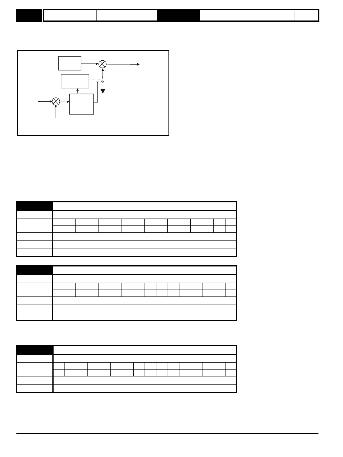
Menu 4
Kp Pr
4.13
Ki Pr
4.14
Current limit
active
1
0
current
limit
Post ramp
reference
Ramp
Active
current
-
+
Parameter
structure
Keypad and
display
Parameter
x.00
Parameter
description format
Advanced parameter
descriptions
PC comms
protocol
Building automation
network
Performance RFC mode
Open-loop
The motoring current limit applies in either direction of rotation when the machine is producing motoring torque. Similarly the regen current limit
applies in either direction when the machine is producing regenerating torque. The symmetrical current limit can override either motoring or
regenerating current limit if it is set at a lower value than either limit.
The current limits are compared with the active current, and if the current exceeds a limit the error value passes through the PI controller to give a
frequency component which is used to modify the ramp output. The direction of the modification is always to reduce the frequency to zero if the active
current is over the motoring limit, or to increase the frequency towards the maximum if the current is over the regenerating limit. Even when the
current limit is active the ramp still operates, therefore the proportional and integral gains (Pr 4.13 and Pr 4.14) must be high enough to counter the
effects of the ramp. See Pr 4.13 and Pr 4.14 on page 70 for gain setting.
RFC
The motoring current limit applies in either direction of rotation when the machine is producing motoring torque. Similarly the regen current limit
applies in either direction when the machine is producing regenerating torque. The symmetrical current limit can override either motoring or
regenerating current limit if it is set at a lower value than either limit.
4.08 Torque reference
Drive modes Open-loop, RFC
Coding
Bit SP FI DE Txt VM DP ND RA NC NV PT US RW BU PS
12 11
Range Open-loop, RFC ±USER_CURRENT_MAX %
Default Open-loop, RFC 0.00
Update rate 4ms read
4.09 Torque offset
Drive modes Open-loop, RFC
Coding
Bit SP FI DE Txt VM DP ND RA NC NV PT US RW BU PS
11 11
Range Open-loop, RFC ±USER_CURRENT_MAX %
Default Open-loop, RFC 0.0
Update rate 4ms read
The torque offset is added to the torque reference when Pr 4.10 is 1. The torque offset is updated every 4ms when connected to an analog input, and
so Pr 4.08 should be used for fast updating if required.
4.10 Torque offset select
Drive modes Open-loop, RFC
Coding
Default Open-loop, RFC 0
Update rate 4ms read
Bit SP FI DE Txt VM DP ND RA NC NV PT US RW BU PS
111
68 Affinity Advanced User Guide
Issue Number: 3
Page 69

Parameter
P Pr
4.13
I Pr
4.14
Current
demand
Active
current
Frequency
reference
+
-
structure
Keypad and
display
Parameter
x.00
Parameter
description format
Advanced parameter
descriptions
PC comms
protocol
Building automation
network
Performance RFC mode
Menu 4
4.11 Torque mode selector
Drive modes Open-loop, RFC
Coding
Bit SP FI DE Txt VM DP ND RA NC NV PT US RW BU PS
111
Range Open-loop, RFC 0 to 1
Default Open-loop, RFC 0
Update rate 4ms read
Open loop
If this parameter is 0 normal frequency control is used. If this parameter is set to 1, the current demand is connected to the current PI controller giving
closed loop torque/current demand as shown below. The current error is passed through proportional and integral terms to give a frequency reference
which is limited to the range ±SPEED_FREQ_MAX .
RFC
When this parameter is set to 1, the ramps are not active while the drive is in the run state. When the drive is taken out of the run state but not
disabled, the appropriate stopping mode is used. It is recommended that coast stopping or stopping without ramps is used. However if ramp stop
mode is used, the ramp output is pre-loaded with the actual speed at the changeover point to avoid unwanted jumps in the speed reference.
0: Speed control mode
The torque demand is equal to the speed loop output.
1: Torque control
The torque demand is given by the sum of the torque reference and the torque offset if enabled. The speed is not limited in any way, however the
drive will trip at the overspeed threshold if runaway occurs.
4.12 Current demand filter 1
Drive modes RFC
Coding
Bit SP FI DE Txt VM DP ND RA NC NV PT US RW BU PS
1 111
Range RFC 0.0 to 25.0 ms
Default RFC 0.0
Update rate Background read
This filter introduces a lag in the speed loop, and therefore the speed loop gains may need to be reduced to maintain stability as the filter time
constant is increased. Alternative time constants/filters can be selected depending on the value of the speed controller gain selector (Pr 3.16). If Pr
3.16 = 0 Pr 4.12 is used, if Pr 3.16 = 1 Pr 4.23 is used.
4.13 Current controller Kp gain
Drive modes Open-loop, RFC
Coding
Bit SP FI DE Txt VM DP ND RA NC NV PT US RW BU PS
111
Range Open-loop, RFC 0 to 30,000
Default
Second motor
parameter
Drive voltage rating:
Open-loop,
RFC
RFC Pr 21.22
200V 400V 575V 690V
20 20 20 20
75 150 180 215
Update rate Background read
Affinity Advanced User Guide 69
Issue Number: 3
Page 70

Menu 4
DC Bus
voltage
controller
P Pr
4.13
I Pr
4.14
Frequency
reference
Active current
DC Bus
capacitor
Current
demand
Parameter
structure
Keypad and
display
Parameter
x.00
Parameter
description format
Advanced parameter
descriptions
PC comms
protocol
Building automation
network
Performance RFC mode
4.14 Current controller Ki gain
Drive modes Open-loop, RFC
Coding
Bit SP FI DE Txt VM DP ND RA NC NV PT US RW BU PS
111
Range Open-loop, RFC 0 to 30,000
Default
Second motor
parameter
Drive voltage rating:
Open-loop,
RFC
RFC Pr 21.23
200V 400V 575V 690V
40 40 40 40
1,000 2,000 2,400 3,000
Update rate Background read
Open-loop
These parameters control the proportional and integral gains of the current controller used in the open loop drive. As already mentioned, the current
controller either provides current limits or closed loop torque control by modifying the drive output frequency. The control loop is also used in its torque
mode during mains loss, or when the controlled mode standard ramp is active and the drive is decelerating to regulate the flow of current into the
drive. Although the default settings have been chosen to give suitable gains for less demanding applications, it may be necessary for the user to
adjust the performance of the controller. The following is a guide to setting the gains for different applications.
Current limit operation
The current limits will normally operate with an integral term only, particularly below the point at which field weakening begins. The proportional term
is inherent in the loop. The integral term must be increased sufficiently to counter the effect of the ramp which is still active even in current limit.
For example, if the drive is operating at constant frequency and is overloaded, the current limit system will try to reduce the output frequency to
reduce the load. At the same time the ramp will try to increase the frequency to the demand level. If the integral gain is increased too far, the first signs
of instability will occur when operating around the point where field weakening begins. These oscillations can be reduced by increasing the
proportional gain.
A system has been included to prevent regulation because of the opposite actions of the ramps and the current limit. This can reduce the actual level
that the current limit becomes active by 12.5%. This still allows the current to increase up to the current limit set by the user. However the current limit
flag (Pr 10.09) could become active up to 12.5% below the current limit depending on the ramp rate used.
Torque control
Again the controller will normally operate with an integral term only, particularly below the point where field weakening begins. The first signs of
instability will appear around base speed, and can be reduced by increasing the proportional gain. The controller can be less stable in torque control
mode rather than when it is used for current limiting. This is because load helps to stabilise the controller, and under torque control the drive may
operate with light load. Under current limit the drive is often under heavy load unless the current limits are set at a low level.
Mains loss and controlled standard ramp
The DC bus voltage controller becomes active if mains loss detection is enabled and the drive supply is lost, or controlled standard ramp is being
used and the machine is regenerating. The DC bus controller attempts to hold the DC bus voltage at a fixed level by controlling the flow of current
from the drive inverter into its DC bus capacitors. The output of the DC bus controller is a current demand which is fed into the current PI controller as
shown in the following diagram.
Although it is not usually necessary, the DC bus voltage controller can be adjusted with Pr 5.31. However it may often be necessary to adjust the
current controller gains to obtain the required performance. If the gains are not suitable, it is best to set up the drive in torque control first. Set the
gains to a value that does not cause instability around the point at which field weakening occurs.
It should now be possible to revert back to open loop speed control in standard ramp mode. To test the controller, the supply should be removed while
the motor is running. It is likely that the gains can be increased further if required, because the DC bus voltage controller has a stabilizing effect
provided that the drive is not required to operate in torque control mode.
70 Affinity Advanced User Guide
Issue Number: 3
Page 71

Parameter
structure
Keypad and
display
Parameter
x.00
Parameter
description format
Advanced parameter
descriptions
PC comms
protocol
Building automation
network
Performance RFC mode
Menu 4
RFC
The proportional gain Kp (Pr 4.13) is the most critical value in controlling the performance of the current controllers. Either the value can be set by
auto-tuning (see Pr 5.12), or it can be set by the user so that:-
Kp = (L / T) x (Ifs / Vfs) x (256 / 5)
Where:
T is the sample time of the current controllers. The drive compensates for any change of sample time, and so it should be assumed that the
sample time is equivalent to the lowest sample rate of 167s.
L is the motor inductance. For a servo motor this is half the phase to phase inductance that is normally specified by the manufacturer. For an
induction motor this is the per phase transient inductance (Ls). This is the inductance value stored in Pr 5.24 after the auto-tune test is carried
out.
I
is the peak full scale current feedback = Kc x 2 / 0.45. Where Kc is the current scaling for each size of drive.
fs
V
is the maximum DC bus voltage.
fs
Therefore:
Kp = (L / 167s) x (Kc x 2 / 0.45 / Vfs) x (256 / 5)
= K x L x Kc
Where:
K =
2 / (0.45 x V
x 167s) x (256 / 5)
fs
There is one value of the scaling factor K for each drive voltage rating as shown in the table below
Drive voltage rating
V
fs
K
200V 415V 2,322
400V 830V 1,161
575V 990V 973
690V 1190V 809
The integral gain Ki (Pr 4.14) is less critical and should be set so that
Ki = Kp x 256 x T /
m
where
is the motor time constant/filter (L / R).
m
R is the per phase stator resistance of the motor (i.e. half the resistance measured between two phases).
Therefore
Ki = (K x L x Kc) x 256 x 167us x R / L
= 0.0427 x K x R x Kc
The above equations give the gain values that are calculated by the auto-tune system, and these should give the best response at all switching
frequencies with minimal overshoot. If necessary the gains can be adjusted to improve performance as follows:
1. The integral gain (Ki) can be used to improve the performance of the current controllers by reducing the effects of inverter non-linearity. These
effects become more significant with higher switching frequency. These effects will be more significant for drives with higher current ratings and
higher voltage ratings. If Ki is increased by a factor of 4 it is possible to get up to 10% overshoot in response to a step change of current
reference. For high performance applications, it is recommended that Ki is increased by a factor of 4 from the auto-tuned values. As the inverter
non-linearity is worse with higher switching frequencies it is may be necessary to increase Ki by a factor of 8 for operation with 16kHz switching
frequency.
2. It is possible to increase the proportional gain (Kp) to reduce the response time of the current controllers. If Kpi is increased by a factor of 1.5 then
the response to a step change of reference will give 12.5% overshoot. It is recommended that Ki is increased in preference to Kpi.
4.15 Thermal time constant/filter
Drive modes Open-loop, RFC
Coding
Bit SP FI DE Txt VM DP ND RA NC NV PT US RW BU PS
111
Range Open-loop, RFC 0.0 to 3000.0
Default Open-loop, RFC 89.0
Second motor
parameter
Open-loop, RFC Pr 21.16
Update rate Background read
Affinity Advanced User Guide 71
Issue Number: 3
Page 72

Menu 4
I /(K*Motor Rated Current)
22
Te mp
C
R
Motor total
current (Pr 4.01)
as a percentage
of motor rated
current
Motor speed as a
percentage of base speed
100%
Max. permissible
continuous
current
100%
I t protection operates in this region
2
70%
50%15%
Open loop: Proportion of rated frequency Pr 5.06.
RFC: Proportion of rated speed Pr 5.08.
Rated current (Pr 5.07 or Pr 21.07) drive current rating.
Parameter
structure
Keypad and
display
Parameter
x.00
Parameter
description format
Advanced parameter
descriptions
PC comms
protocol
Building automation
network
Performance RFC mode
4.16 Thermal protection mode
Drive modes Open-loop, RFC
Coding
Bit SP FI DE Txt VM DP ND RA NC NV PT US RW BU PS
1 111
Range Open-loop, RFC 0 to 1
Default Open-loop, RFC 0
Update rate Background read
The motor is modelled thermally in a way that is equivalent to the electrical circuit shown as follows.
The temperature of the motor as a percentage of maximum temperature, with a constant current magnitude of I, constant value of K and constant
value of motor rated current (set by Pr 5.07 or Pr 21.07) after time t is given by
Temp = [I
2
/ (K x Motor rated current)2] (1 - e
-t/
) x 100%
This assumes that the maximum allowed motor temperature is produced by K x Motor rated current and that is the thermal time constant/filter of the
point in the motor that reaches its maximum allowed temperature first. is defined by Pr 4.15. The estimated motor temperature is given by Pr 4.19 as
a percentage of maximum temperature. If Pr 4.15 has a value between 0.0 and 1.0 the thermal time constant/filter is taken as 1.0.
If the rated current (defined by Pr 5.07 or Pr 21.07 depending on which motor is selected) is less or equal to the drive current scaling then Pr 4.25 can
be used to select 2 alternative protection characteristics (see diagram below). If Pr 4.25 is 0 the characteristic is for a motor which can operate at
rated current over the whole speed range. Induction motors with this type of characteristic normally have forced cooling. If Pr 4.25 is 1 the
characteristic is intended for motors where the cooling effect of motor fan reduces with reduced motor speed below half of rated speed. The maximum
value for K is 1.05, so that above the knee of the characteristics the motor can operate continuously up to 105% current.
The maximum value for K is 1.01, so that above the knee of the characteristics the motor can operate continuously up to 101% current.
72 Affinity Advanced User Guide
Issue Number: 3
Page 73
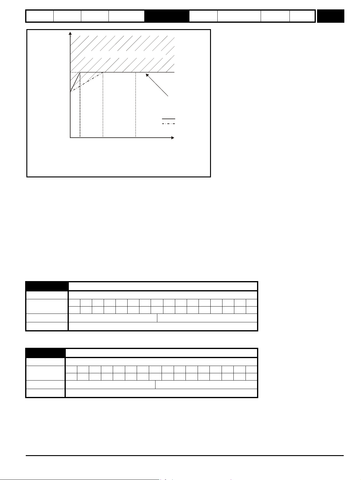
Parameter
Motor total
current (Pr 4.01)
as a percentage
of motor rated
current
Motor speed as a
percentage of base speed
100%
Max. permissible
continuous
current
100%
I t protection operates in this region
2
70%
50%15%
Pr = 0
Pr = 1
4.25
4.25
Open loop: Proportion of rated frequency Pr 5.06.
RFC: Proportion of rated speed Pr 5.08.
Rated current (Pr 5.07 or Pr 21.07) drive current rating.
structure
Keypad and
display
Parameter
x.00
Parameter
description format
Advanced parameter
descriptions
PC comms
protocol
Building automation
network
Performance RFC mode
Menu 4
When the estimated temperature reaches 100% the drive takes some action depending on the setting of Pr 4.16. If Pr 4.16 is 0, the drive trips when
the threshold is reached. If Pr 4.16 is 1, the current limit is reduced to (K - 0.05) x 100% when the temperature is 100%. The current limit is set back
to the user defined level when the temperature falls below 95%.
The time for some action to be taken by the drive from cold with constant motor current is given by:
T
= -(Pr 4.15) x ln(1 - (K x Pr 5.07 / Pr 4.01)2)
trip
Alternatively the thermal time constant/filter can be calculated from the trip time with a given current from:
Pr 4.15 = -T
/ ln(1 - (K / Overload)2)
trip
For example, if the drive should trip after supplying 150% overload for 60 seconds with K = 1.05 then
Pr 4.15 = -60 / ln(1 - (1.05 / 1.50)
2
) = 89
The thermal model temperature accumulator is reset to zero at power-up and accumulates the temperature of the motor while the drive remains
powered-up. Each time Pr 11. 45 is changed to select a new motor, or the rated current defined by Pr 5.07 or Pr 21.07 (depending on the motor
selected) is altered, the accumulator is reset to zero.
4.17 Reactive current
Drive modes Open-loop, RFC
Coding
Bit SP FI DE Txt VM DP ND RA NC NV PT US RW BU PS
112111
Range Open-loop, RFC ±DRIVE_CURRENT_MAX A
Update rate 4ms write
The drive reactive current is shown in this parameter for all modes.
4.18 Overriding current limit
Drive modes Open-loop, RFC
Coding
Range Open-loop, RFC 0 to TORQUE_PROD_CURRENT_MAX %
Update rate Background write
The current limit applied at any time depends on whether the drive is motoring or regenerating and also on the level of the symmetrical current limit.
Bit SP FI DE Txt VM DP ND RA NC NV PT US RW BU PS
Pr 4.18 gives the limit level that applies at any instant.
Affinity Advanced User Guide 73
Issue Number: 3
111 1 1 1
Page 74

Menu 4
Parameter
structure
Keypad and
display
Parameter
x.00
Parameter
description format
Advanced parameter
descriptions
PC comms
protocol
Building automation
network
Performance RFC mode
4.19 Overload accumulator
Drive modes Open-loop, RFC
Coding
Bit SP FI DE Txt VM DP ND RA NC NV PT US RW BU PS
11 1 1 1
Range Open-loop, RFC 0 to 100.0 %
Update rate Background write
See Pr 4.16 on page 72.
4.20 Percentage load
Drive modes Open-loop, RFC
Coding
Bit SP FI DE Txt VM DP ND RA NC NV PT US RW BU PS
111111
Range Open-loop, RFC ±USER_CURRENT_MAX %
Update rate Background write
Open-loop, RFC
This parameter displays the actual torque producing current (Pr 4.02) as a percentage of rated active current. Positive values indicate motoring and
negative values indicate regenerating.
4.22 Inertia compensation enable
Drive modes RFC
Coding
Bit SP FI DE Txt VM DP ND RA NC NV PT US RW BU PS
111
Default RFC 0
Update rate Background read
If this parameter is set to 1, the drive calculates a torque reference from the motor and load inertia (Pr 3.18), and the rate of change of speed
reference. The torque reference is added to the speed controller output to provide inertia compensation. This can be used in speed or torque control
applications to produce the torque required to accelerate or decelerate the load inertia.
4.23 Current demand filter 2
Drive modes RFC
Coding
Bit SP FI DE Txt VM DP ND RA NC NV PT US RW BU PS
1111
Range RFC 0.0 to 25.0 ms
Default RFC 0.0
Update rate Background read
The current demand filter time constant/filter is defined by this parameter if the speed gain select (Pr 3.16) is 1.
4.24 User current maximum scaling
Drive modes Open-loop, RFC
Coding
Bit SP FI DE Txt VM DP ND RA NC NV PT US RW BU PS
11 1 111
Range Open-loop, RFC 0.0 to TORQUE_PROD_CURRENT_MAX %
Default
Open-loop
RFC
165.0*
175.0*
Update rate Background read
* These are the maximum default values. If the variable maximum of this parameter (TORQUE_PROD_CURRENT_MAX which is defined by
MOTOR1_CURRENT_LIMIT_MAX or MOTOR2_CURRENT_LIMIT_MAX depending on which motor map is active) gives a lower value with the
default value of Motor rated current (Pr 5.07 or Pr 21.07) default of this parameter is at the lower value.
The maximum for Pr 4.08 and Pr 4.20 is defined by this parameter
74 Affinity Advanced User Guide
Issue Number: 3
Page 75

Parameter
NOTE
structure
Keypad and
display
Parameter
x.00
Parameter
description format
Advanced parameter
descriptions
PC comms
protocol
Building automation
network
Performance RFC mode
Menu 4
4.25 Low speed thermal protection mode
Drive modes Open-loop, RFC
Coding
Bit SP FI DE Txt VM DP ND RA NC NV PT US RW BU PS
111
Default Open-loop, RFC 1
Update rate Background read
See Pr 4.16 on page 72.
Pr 4.25 is always set to 1
4.26 Percentage torque
Drive modes Open-loop
Coding
Bit SP FI DE Txt VM DP ND RA NC NV PT US RW BU PS
111111
Default Open-loop ±USER_CURRENT_MAX %
Update rate Background read
Pr 4.26 shows the torque producing current (Pr 4.02) as a percentage of the active torque producing current, but with an additional adjustment above
base speed so that this parameter shows percentage torque. Below base speed Pr 4.26 is equal to Pr 4.20. Above base speed the percentage torque
producing current (shown in Pr 4.20) is adjusted as follows:
Pr 4.26 = Pr 4.20 x rated frequency / frequency
4.27 Low load detection level
Drive modes Open-loop, RFC
Coding
Bit SP FI DE Txt VM DP ND RA NC NV PT US RW BU PS
1111
Range Open-loop, RFC 0.0 to 100.0%
Default Open-loop, RFC 0.0
Update rate Background read
4.28 Low load detection speed / frequency threshold
Drive modes Open-loop, RFC
Coding
Bit SP FI DE Txt VM DP ND RA NC NV PT US RW BU PS
11 1 111
Range Open-loop, RFC 0.0 to SPEED_FREQ_MAX Hz/rpm
Default Open-loop, RFC 0.0
Update rate Background read
4.29 Trip on abnormal load detection
Drive modes Open-loop, RFC
Coding
Bit SP FI DE Txt VM DP ND RA NC NV PT US RW BU PS
11
Default Open-loop, RFC 0
Update rate Background read
Affinity Advanced User Guide 75
Issue Number: 3
Page 76

Menu 4
0
20
40
60
80
100
120
-100 -50 0 50 100
Motor speed (% Rated)
Typical load (% Rated)
04.28
-04.28
04.27
Parameter
structure
Keypad and
display
Parameter
x.00
Parameter
description format
Advanced parameter
descriptions
PC comms
protocol
Building automation
network
Performance RFC mode
The low load detection function is provided so that loss of load can be detected and the necessary action taken. The low load detection function is
disabled if Pr 4.27 is set to zero.
In order that the detector can be used with typical fan and pump load characteristics (i.e. where the load is relatively light at low motor speed), the
detector is only active when the output frequency or speed is above the level defined by Pr 4.28. The motor must also be at the required speed (i.e.
not accelerating or decelerating), so Pr 10.06 (At Speed) must be 1 for the low load detector to be active.
Once the detector is active, the low load condition is detected when Pr 4.20 (percentage load) falls below Pr 4.27, so the condition for detecting low
load is given by:
(Pr 10.06 = 1) AND (|Output frequency or speed| > Pr 4.28) AND (Pr 4.20 < Pr 4.27)
If Pr 4.29 is zero when low load is detected, then a "Load" warning message is displayed on the keypad. If Pr 4.29 is 1 then a drive trip is initiated.
The diagram below shows a typical fan load and operating areas (shaded), where the low load detection is active.
76 Affinity Advanced User Guide
Issue Number: 3
Page 77

Parameter
2.01
Post ramp
reference
+
+
5.10
5.11
Motor rated
power factor
Motor number
of poles
5.02
Motor
voltage
5.03
Total motor
power (kW)
Ö 3xVxI
Volt
L1 L2 L3
5.05
DC Bus
voltage
5.09
Motor rated
voltage
5.07
5.08
Motor rated
current
Motor rated
full load RPM
5.06
Motor rated
frequency
5.23
Voltage offset
5.17
Stator
resistance
5.15
Voltage boost
5.13
Dynamic V/f
select
Transient
inductance
4.02
4.20
4.17
4.01
Motor
current
magnitude
Motor magnetising
current
Motor active
current
Percentage
active current
Motormap
5.12
Autotune
5.24
5.14
Voltage
mode
5.01
Motor
frequency
5.04
Estimated
motor speed
1
0
Slip
compensation
0.XX
0.XX
Key
Read-write (RW)
parameter
Read-only (RO)
parameter
Input
terminals
Output
terminals
X
X
X
X
Slip
compensation
enable
5.27
The parameters are all shown at their default settings
5.18
5.19
PWM
switching
frequency
High stability
space vector
modulation
Hertz
5.20
5.35
Quasi square
wave enable
Disable auto
switching
frequency
change
5.31
Voltage
controller
gain
structure
Keypad and
display
Parameter
x.00
Parameter
description format
5.7 Menu 5: Motor control
Open loop
Figure 5-7 Menu 5 Open-loop logic diagram
Advanced parameter
descriptions
PC comms
protocol
Building automation
network
Performance RFC mode
Menu 5
Affinity Advanced User Guide 77
Issue Number: 3
Page 78

Menu 5
3.04
5.06
Motor rated
frequency
5.08
Motor full load
rated speed
5.09
Motor rated
voltage
5.10
Motor rated
power factor
5.25
Motor stator
inductance
5.29
Motor saturation
break-point 1
5.30
Motor saturation
break-point 2
5.07
Motor rated
current
5.11
Motor number
of poles
5.17
Motor stator
resistance
5.24
Motor transient
inductance
Flux Calculator
Current limits
Current control
Overload detection
Current loop gains
Torque reference
Current demand filter
Menu 4
Reference
frame
transformation
3.02
Speed
feedback
Speed-loop
controller
output
Position
feedback
Flux
magnitude
Current
references
Current
feedback
5.01
Flux angle
5.12
5.15
5.26
5.31
Auto-tune
Low frequency voltage boost
High dynamic performance enable
Voltage controller gain
0.XX
0.XX
Key
Read-write
(RW)
parameter
Read-only (RO)
parameter
Input
terminals
Output
terminals
The parameters are all shown at their default settings
RFC sensorless
speed feedback
calculator
Parameter
structure
Keypad and
display
RFC
Figure 5-8 Menu 5 RFC logic diagram
Parameter
x.00
Parameter
description format
Advanced parameter
descriptions
PC comms
protocol
Building automation
network
Performance RFC mode
78 Affinity Advanced User Guide
Issue Number: 3
Page 79

Parameter
4.02
4.17
4.01
5.09
Motor rated
voltage
5.21
Field gain
reduction
Flux Controller
5.18
Maximum switching
frequency
Modulator
5.03
Power calculation (V x 1)
5.02
Output
voltage
Output
power
5.05
Voltage reference
U
V
W
DC bus
voltage
Motor
current
magnitude
Motor magnetising
current
Motor active
current
5.35
Disable auto
switching
frequencychange
structure
Keypad and
display
Parameter
x.00
Parameter
description format
Advanced parameter
descriptions
PC comms
protocol
Building automation
network
Performance RFC mode
Menu 5
Affinity Advanced User Guide 79
Issue Number: 3
Page 80
Menu 5
Parameter
structure
Keypad and
display
Parameter
x.00
Parameter
description format
Advanced parameter
descriptions
PC comms
protocol
Building automation
network
Performance RFC mode
5.01 Output frequency
Drive modes Open-loop, RFC
Bit SP FI DE Txt VM DP ND RA NC NV PT US RW BU PS
Coding
111111
RFC: VM = 0
Range
Open-loop
RFC
±SPEED_FREQ_MAX Hz
±1250.0 Hz
Update rate 250s write
Open-loop
Although the range for scaling purposes is ±SPEED_FREQ_MAX, the actual parameter value can be increased beyond this range by slip
compensation. This parameter gives the output frequency of the drive, i.e. the sum of the post ramp reference and the slip compensation.
RFC
In these modes the output frequency is not controlled directly, and so the output frequency displayed in this parameter is calculated by measuring the
frequency of the controller reference frame.
5.02 Output voltage
Drive modes Open-loop, RFC
Coding
Bit SP FI DE Txt VM DP ND RA NC NV PT US RW BU PS
1 1111
Range Open-loop, RFC 0 to AC_VOLTAGE_MAX V
Update rate Background write
This is the modulus of the rms line to line voltage at the inverter output at the drive output frequency.
5.03 Output power
Drive modes Open-loop, RFC
Coding
Bit SP FI DE Txt VM DP ND RA NC NV PT US RW BU PS
112111
Range Open-loop, RFC ±POWER_MAX kW
Update rate Background write
Open-loop and RFC mode
The output power is the dot product of the output voltage and current vectors. Positive power indicates power flowing from the drive to the motor
(motoring), and negative power indicates power flowing from the motor to the drive (regen).
5.04 Motor rpm
Drive modes Open-loop
Coding
Bit SP FI DE Txt VM DP ND RA NC NV PT US RW BU PS
1111
Range Open-loop ±180,000 rpm
Update rate Background write
The motor rpm is calculated from the post ramp reference (Pr 2.01) for normal operation, or the slave frequency demand (Pr 3.01) if frequency slaving
is being used. The speed of rotation is calculated as follows:
rpm = 60 x frequency / no. of pole pairs
If frequency slaving is being used there will be an error due to the slip frequency. However, in normal operation the result will be reasonably accurate
provided that the slip compensation has been set up correctly in the rated full load rpm parameter (Pr 5.08).
5.05 DC bus voltage
Drive modes Open-loop, RFC
Coding
Bit SP FI DE Txt VM DP ND RA NC NV PT US RW BU PS
1 1111 1
Range Open-loop, RFC 0 to +dc _VOLTAGE_MAX V
Update rate Background write
Voltage across the internal DC bus of the drive.
80 Affinity Advanced User Guide
Issue Number: 3
Page 81

Parameter
structure
Keypad and
display
Parameter
x.00
Parameter
description format
Advanced parameter
descriptions
PC comms
protocol
Building automation
network
Performance RFC mode
Menu 5
5.06 Rated frequency
Drive modes Open-loop, RFC
Coding
Range
Bit SP FI DE Txt VM DP ND RA NC NV PT US RW BU PS
1111
Open-loop
RFC
0 to 3000.0 Hz
0 to 1250.0 Hz
Default Open-loop, RFC EUR: 50.0 Hz, USA: 60.0 Hz
Second motor
parameter
Open-loop, RFC Pr 21.06
Update rate Background read
Open loop
The motor rated frequency and the motor rated voltage (Pr 5.09) are used to define the voltage to frequency characteristic applied to the motor (see
Pr 5.09 on page 82). The motor rated frequency is also used in conjunction with the motor full load rpm to calculate the rated slip for slip
compensation (see Pr 5.08 on page 82).
RFC
The motor rated frequency is used in conjunction with the motor full load rpm to calculate the rated slip of the machine for the vector control algorithm
(see Pr 5.08 on page 82). The test frequency used for the rotating auto-tune test is
2
/3 x Pr 5.06.
5.07 Motor rated current
Drive modes Open-loop, RFC
Coding
Bit SP FI DE Txt VM DP ND RA NC NV PT US RW BU PS
12 1 111
Range Open-loop, RFC 0 to RATED_CURRENT_MAX A
Default Open-loop, RFC
Second motor
parameter
Open-loop, RFC Pr 21.07
Drive current scaling (i.e. the value of
Pr 11.32 )
Update rate Background read
The rated current should be set at the motor nameplate value for rated current. The value of this parameter is used as follows:
Current limits
Motor thermal protection
Open-loop
Vector mode voltage control
Slip compensation
Dynamic V to F control
Current limits
RFC
Motor thermal protection
Vector control algorithm
Affinity Advanced User Guide 81
Issue Number: 3
Page 82
Menu 5
Parameter
structure
Keypad and
display
Parameter
x.00
Parameter
description format
Advanced parameter
descriptions
PC comms
protocol
Building automation
network
Performance RFC mode
5.08 Rated load rpm / Rated speed
Drive modes Open-loop, RFC
Bit SP FI DE Txt VM DP ND RA NC NV PT US RW BU PS
Coding
111
RFC DP=2
Range
Default
Second motor
parameter
Open-loop,
RFC
Open-loop,
RFC
Open-loop, RFC Pr 21.08
0 to 180,000 rpm
0.00 to 40,000.00 rpm
EUR: 1,500, USA: 1,800
EUR: 1450.00, USA: 1,770.00
Update rate Background read
Open loop
The rated load rpm is used with the motor rated frequency and number of poles to calculate the rated slip of induction machines in Hz.
rated slip (Hz) = rated motor frequency - (no. of pole pairs x motor full load rpm / 60)
= Pr 5.06 - ((Pr 5.11 / 2) x Pr 5.08 / 60)
If Pr 5.08 is set to 0 or to synchronous speed slip, compensation is disabled. If slip compensation is required, this parameter should be set to the
nameplate value, which should give the correct rpm for a hot machine. Sometimes it will be necessary to adjust this value when the drive is
commissioned, because the nameplate value may be inaccurate. Slip compensation will operate correctly both below base speed and within the field
weakening region. Slip compensation is normally used to correct for the motor speed to prevent speed droop as load is applied. The rated load rpm
can be set higher than synchronous speed to deliberately introduce speed droop. This can be useful to aid load sharing with mechanically coupled
motors.
RFC
Rated load rpm is used with motor rated frequency to determine the full load slip of the motor which is used by the vector control algorithm. Incorrect
setting of this parameter has the following effects:
• Reduced efficiency of motor operation
• Reduction of maximum torque available from the motor
• Reduced transient performance
• Inaccurate control of absolute torque in torque control modes
The nameplate value is normally the value for a hot machine, however, some adjustment may be required when the drive is commissioned if the
nameplate value is inaccurate.
5.09 Rated voltage
Drive modes Open-loop, RFC
Coding
Bit SP FI DE Txt VM DP ND RA NC NV PT US RW BU PS
11 111
Range Open-loop, RFC 0 to AC_VOLTAGE_SET_MAX V
200V rating drive: 230V
Default Open-loop, RFC
400V rating drive: EUR: 400V, USA: 480V
600V rating drive: 575V
690V rating drive: 690V
Second motor
parameter
Open-loop, RFC Pr 21.09
Update rate Level 4 read
Open loop
The rated voltage is used in conjunction with the motor rated frequency (Pr 5.06) to define the voltage to frequency characteristic applied to the motor.
The following operating methods selected by Pr 5.14 are used to define the drive frequency to voltage characteristic.
Open-loop vector mode: Ur_S, Ur or Ur_I
A linear characteristic is used from 0Hz to rated frequency, and then a constant voltage above rated frequency. When the drive operates between
rated frequency/50 and rated frequency/4, full vector based stator resistance (Rs) compensation is applied.
However there is a delay of 0.5s when the drive is enabled during which only partial vector based compensation is applied to allow the machine flux
to build up. When the drive operates between rated frequency/4 and rated frequency/2 the Rs compensation is gradually reduced to zero as the
frequency increases. For the vector modes to operate correctly the stator resistance (Pr 5.17), motor rated power factor (Pr 5.10) and voltage offset
(Pr 5.23) are all required to be set up accurately.
82 Affinity Advanced User Guide
Issue Number: 3
Page 83

Parameter
Voltage
boost Pr
5.15
Output
voltage
Pr
5.09
Pr / 2
5.09
Pr / 2
5.06
Pr
5.06
Output
frequency
Output voltage characteristic
Pr
5.09
Pr
5.15
Pr
5.06
Pr + [(freq/Pr ) x (Pr - Pr )]
5.15 5.06 5.09 5.15
2
structure
Keypad and
display
Parameter
x.00
Parameter
description format
Advanced parameter
descriptions
PC comms
protocol
Building automation
network
Performance RFC mode
Menu 5
Fixed boost mode: Fd
A linear characteristic is used from 0Hz to rated frequency, and then constant voltage above rated frequency. Low frequency voltage boost as defined
by Pr 5.15 is applied as shown below.
Square law mode: SrE
A square law characteristic is used from 0Hz to rated frequency, and then constant voltage above rated frequency. Low frequency voltage boost
raises the start point of the square law characteristic as shown below.
RFC
The rated voltage is used by the field controller to limit the voltage applied to the motor. Normally this is set to the nameplate value.
In order that current control can be maintained, it is necessary for the drive to leave some 'headroom' between the machine terminal voltage and the
maximum available drive output voltage. The drive allows over-modulation of the PWM inverter, which can produce a fundamental voltage that is
higher than the drive input voltage, but would cause substantial odd harmonic distortion if used in steady state operation.
Accordingly the drive uses a headroom limit which allows the inverter to give a steady state output voltage equivalent to the input voltage minus
voltage drops inside the drive. This gives enough headroom for the current controllers to operate satisfactorily. However, for good transient
performance at high speed the rated voltage should be set below 95% of the minimum supply voltage to the drive.
The rated voltage is also used in conjunction with the motor rated frequency (Pr 5.06) during the rotating auto-tune test (see Pr 5.12 on page 84), and
in the calculations required for automatic optimization of the rated motor slip. It is important therefore, that the correct rated voltage for the motor is
used.
In some applications it may be necessary to restrict the voltage applied to the motor to a level lower than the nameplate rated voltage of the motor. In
this case the rated frequency (Pr 5.06) must be adjusted to maintain the ratio of rated voltage and frequency given on the motor nameplate. The rated
frequency will then be different to the nameplate value, and so the rated speed must be changed from the nameplate value to give the correct rated
slip.
Affinity Advanced User Guide 83
Issue Number: 3
Page 84
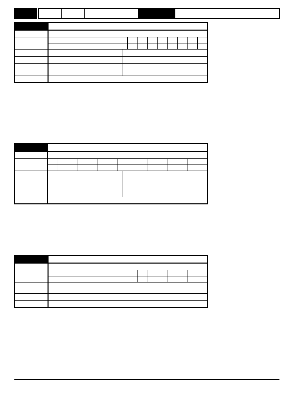
Menu 5
Parameter
structure
Keypad and
display
Parameter
x.00
Parameter
description format
Advanced parameter
descriptions
PC comms
protocol
Building automation
network
Performance RFC mode
5.10 Rated power factor
Drive modes Open-loop, RFC
Coding
Bit SP FI DE Txt VM DP ND RA NC NV PT US RW BU PS
3 1 111
Range Open-loop, RFC 0.000 to 1.000
Default Open-loop, RFC 0.850
Second motor
parameter
Open-loop, RFC Pr 21.10
Update rate Background read
Open loop
The power factor is the true power factor of the motor i.e. the angle between the motor voltage and current. The power factor is used in conjunction
with the motor rated current (Pr 5.07), to calculate the rated active current and magnetizing current of the motor. The rated active current is used
extensively to control the drive, and the magnetizing current is used in vector mode Rs compensation. It is important that this parameter is set up
correctly.
RFC
The power factor is the true power factor of the motor, i.e. the angle between the motor voltage and current. If the stator inductance is set to zero
(Pr 5.25), then the power factor is used in conjunction with the motor rated current and other motor parameters, to calculate the rated active and
magnetizing currents which are used in the vector control algorithm. If the stator inductance has a non-zero value, this parameter is not used by the
drive, but is continuously written with a calculated value of power factor.
5.11 Number of motor poles
Drive modes Open-loop, RFC
Coding
Bit SP FI DE Txt VM DP ND RA NC NV PT US RW BU PS
1 111
Range Open-loop, RFC 0 to 60 (Auto to 120 POLE)
Default Open-loop, RFC 0 (Auto)
Second motor
parameter
Open-loop, RFC Pr 21.11
Update rate Background read
Open-loop
This parameter is used in the calculation of motor speed and in applying the correct slip compensation. When auto is selected the number of motor
poles is automatically calculated from the rated frequency (Pr 5.06) and the rated load rpm (Pr 5.08). The number of poles = 120 * rated frequency /
rpm rounded to the nearest even number.
RFC
This parameter must be set correctly for the vector control algorithms to operate correctly. When auto is selected the number of motor poles is
automatically calculated from the rated frequency (Pr 5.06) and the rated load rpm (Pr 5.08). The number of poles = 120 * rated frequency / rpm
rounded to the nearest even number.
5.12 Autotune
Drive modes Open-loop, RFC
Coding
Range
Bit SP FI DE Txt VM DP ND RA NC NV PT US RW BU PS
111
Open-loop,
RFC
0 to 2
0 to 4
Default Open-loop, RFC 0
Update rate Background read
If this parameter is set to a non-zero value, the drive is enabled and a run command is applied in either direction. The drive performs an auto-tune test
for the drive modes listed below. All tests that rotate the motor are carried out in the forward direction if Pr 1.12 = 0 or the reverse direction if
Pr 1.12 = 1.
For example, if the test is initiated by applying run reverse (Pr 6.32 = 1), the test is performed in the reverse direction. It should be noted however that
the motor may jump in either direction by up to half an electrical revolution at the start of the phasing test, and then move in the required direction for
the remainder of the test. The test will not start unless the drive is disabled before the test is initiated by applying the enable or run, i.e. it will not start
if the drive is in the stop state.
In RFC mode it is not possible to go into the stop state if Pr 5.12 has a non-zero value. (If Pr 5.12 is set to 4 in RFC mode then no test is carried out,
but the current loop gains are re-calculated. For these actions the drive does not need to be enabled.)
84 Affinity Advanced User Guide
Issue Number: 3
Page 85
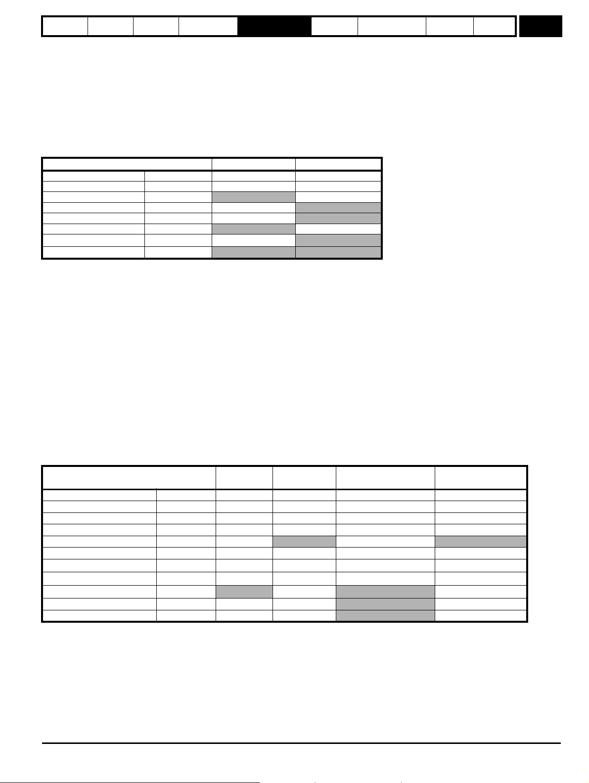
Parameter
structure
Keypad and
display
Parameter
x.00
Parameter
description format
Advanced parameter
descriptions
PC comms
protocol
Building automation
network
Performance RFC mode
Menu 5
It is important that the motor is at standstill before the auto-tune test is performed if the correct results are to be obtained. The parameters modified by
the auto-tune tests are defined below when the second motor parameters are not selected (i.e. Pr 11. 45 = 0).
If the second motor is selected for the duration of the tests (i.e. Pr 11.45 = 1), the second motor parameters in menu 21 are modified instead, and not
the parameters described below. When the test has successfully completed, the drive is disabled and will enter the inhibit state.
The motor can only be restarted if the enable is removed either from the enable input if Pr 6.15 is set to zero, or by using control word (Pr 6.42). As
the tests progresses, the calculated parameters are saved to EEPROM as indicated. If for any reason the test fails and the drive trips, no further
parameters are calculated or stored in EEPROM. (If the drive is in Auto or Boot cloning modes (Pr 11.42 = 3 or 4) the parameters are also saved to
the SMARTCARD where it is indicated that parameters are saved to EEPROM.)
Open-loop
In this mode the following parameters are used in the vector control algorithm.
Parameter Basic algorithm Slip compensation
Rated frequency Pr 5.06
Rated current Pr 5.07
Rated load rpm Pr 5.08
Rated voltage Pr 5.09
Power factor Pr 5.10
No. of poles Pr 5.11
Stator resistance (R
Transient inductance (Ls)
)
s
Pr 5.17
Pr 5.24
All the above parameters can be set by the user. The auto-tune test can be used to overwrite the user or default settings as described below.
Accurate values of stator resistance and voltage offset are required even for moderate performance in vector mode (an accurate value of power factor
is less critical).
1: Stationary test
• A stationary test is performed to measure the stator resistance (Pr 5.17) and voltage offset (Pr 5.23). The power factor (Pr 5.10) is not affected.
•Pr 5.17 and Pr 5.23 are saved to EEPROM.
2: Rotating test
• The stationary test is performed and the parameters saved to EEPROM as described above.
• A stationary test is performed to measure the transient inductance (Pr 5.24). The transient inductance is not used directly by the drive, but is an
intermediate value in determining the power factor after the rotating test.
•Pr 5.24 is saved to EEPROM.
• A rotating test is performed in which the motor is accelerated with the currently selected ramps to
2
/3 of rated speed and held at this speed for
several seconds. Once the test is complete the power factor (Pr 5.10) is updated and the motor coasts to a stop. The motor should be unloaded
for this test to produce correct results.
•Pr 5.10 is saved to EEPROM.
RFC
In this mode the following parameters are used in the vector control algorithm.
Parameter
is zero If Ls is not zero
If L
s
Required for good
performance
Required for excellent
performance
Rated frequency Pr 5.06
Rated current Pr 5.07
Rated load rpm Pr 5.08
Rated Voltage Pr 5.09
Power factor Pr 5.10
No. of poles Pr 5.11
Stator resistance (R
Transient inductance (L
Stator inductance (L
Motor saturation breakpoint 1 Pr 5.29
Motor saturation breakpoint 2 Pr 5.30
)
s
)
s
)
s
Pr 5.17
Pr 5.24
Pr 5.25
All the above parameters can be set by the user. The motor set-up is constantly recalculated in the background task, therefore modifying these
parameters even after auto-tune will affect the performance of the drive. The auto-tune test can be used to overwrite the user or default settings as
described below. It should be noted that the current loop gains (Pr 4.13 and 4.14) are not updated as part of any test if either the stator resistance or
the transient inductance for the active motor map are zero.
Affinity Advanced User Guide 85
Issue Number: 3
Page 86

Menu 5
Parameter
structure
Keypad and
display
Parameter
x.00
Parameter
description format
Advanced parameter
descriptions
PC comms
protocol
Building automation
network
Performance RFC mode
1. Stationary test
• A stationary test is performed to measure the stator resistance (Pr 5.17)
•Pr 5.17 is saved to EEPROM.
• A stationary test is performed to measure the transient inductance (Pr 5.24). When this test is complete the current loop gains (Pr 4.13 and Pr
4.14) are over-written with the correct values based on the calculations given in Menu 4. A moderately accurate value of
as described in menu
1
4 can be obtained from the measured stator resistance and transient inductance to set the correct current limits and flux level in the motor.
•Pr 4.13, Pr 4.14 and Pr 5.24 are saved to EEPROM.
2. Rotating test
• The stationary tests are performed and the parameters saved to EEPROM as described above.
2
• A rotating test is performed in which the motor is accelerated using the ramp rate defined by Pr 2.11 (or Pr 21.04 if motor 2 is selected) to
/3 of
rated frequency and held at this frequency for up to 36 seconds. During the rotating test, the stator inductance (Pr 5.25) and the motor saturation
breakpoints (Pr 5.29 and Pr 5.30) are calculated. The power factor is also modified for user information only, and is not used after this point
because the stator inductance will have a non-zero value. When the test is complete the motor coasts to a stop. The motor should be unloaded
for this test to produce correct results.
•Pr 5.25, Pr 5.29 and Pr 5.30 are saved to EEPROM.
3. Inertia measurement
• The drive attempts to accelerate the motor in the forward direction up to
made, starting with rated torque/16, and then increasing the torque progressively to x
3
/4 x rated load rpm and then back to standstill. Several attempts may be
1
/4, x1/2 and x1 rated torque if the motor cannot be
accelerated to the required speed. 5s acceleration time is allowed during the first four attempts and 60s on the final attempt. If the required speed
is not achieved on the final attempt, the test is aborted and a tuNE1 trip is initiated. If the test is successful, the acceleration and deceleration
times are used to calculate the motor and load inertia which is written to Pr 3.18.
•Pr 3.18 is saved to EEPROM.
The calculated value of inertia is dependant on the value of the motor torque per amp parameter (Pr 5.32), which is calculated by the drive using an
efficiency of 0.9. Therefore the inertia may be inaccurate if the motor efficiency is substantially different from 0.9. However, if the inertia is used for
automatic speed loop gain set up the calculated gains will not be affected because Kt is also used in these calculations and any inaccuracy cancels
out.
The test algorithm attempts to remove the effect of any load on the motor other than the torque required to accelerate and decelerate the motor, i.e.
friction and windage losses, static torque load etc. Provided the average torque during acceleration, and the average torque during deceleration are
the same, the effect of the additional torque is removed and the inertia value is calculated correctly.
4. Current controller gain calculation only
• No current is applied to the motor.
• The current loop gains are calculated based on the value of the motor inductance (Pr 5.24) and resistance (Pr 5.17) and written to Pr 4.13 and
Pr 4.14.
•Pr 4.13 and Pr 4.14 are saved to EEPROM.
This is intended to be used as a method of setting up the current loop gains from user defined values of motor inductance and resistance. The drive
should not be enabled to perform these calculations. If the parameter is set to 4, it is automatically cleared by the drive once the calculation has
completed. It should be noted that the value changes back to zero within a few hundred milliseconds of being set to 4 by the user.
Open-loop, RFC
The auto-tune tests may be aborted by removing the run command or the enable, or if a trip occurs. During the auto-tune tests, the following trips can
occur in addition to the other drive trips.
Trip code Reason Test which can cause trip
tunE1 The motor did not reach the required speed RFC 3
tunE2 The motor could not be stopped RFC 3
tunE3 The calculated inertia is out of range RFC 3
Motor poles or encoder lines set up incorrectly.A trip is
initiated if the speed is not within ±6.25% of the
tunE7
expected no load speed just after the motor has
RFC 2
ramped up to speed. This trip will not occur if the motor
poles are set to more than 12.
tunE Auto-tune stopped before completion All
rS* Stator resistance too high
Open-loop 1, 2
RFC 1
*The rS trip is produced if the drive cannot achieve the necessary current levels to measure the stator resistance during the test (i.e. there is no motor
connected to the drive), or if the necessary current level can be achieved, but the calculated resistance exceeds the maximum values for the
particular drive size or it exceeds 65.000. The maximum measurable value for a particular drive size can be calculated from the following formula.
Rs
= dc _VOLTAGE_MAX x 0.45 / (Kc x 2)
max
where Kc is the current scaling factor for the drive
86 Affinity Advanced User Guide
Issue Number: 3
Page 87
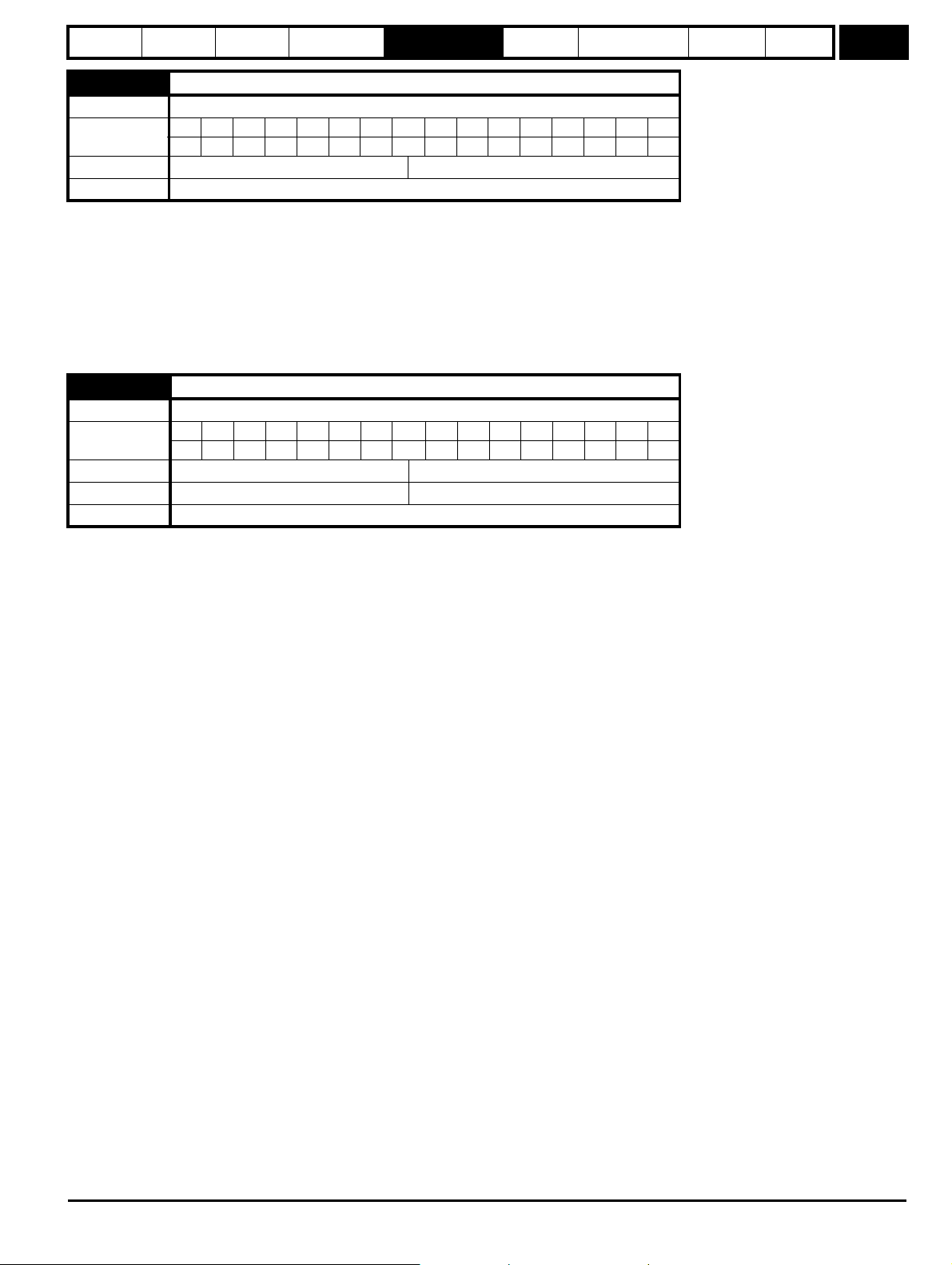
Parameter
structure
Keypad and
display
Parameter
x.00
Parameter
description format
Advanced parameter
descriptions
PC comms
protocol
Building automation
network
Performance RFC mode
Menu 5
5.13 Dynamic V to F / flux optimise select
Drive modes Open-loop, RFC
Coding
Bit SP FI DE Txt VM DP ND RA NC NV PT US RW BU PS
111
Default Open-loop 0
Update rate Background read
Open-loop
Setting this bit enables dynamic V to f mode which is intended for applications where power loss should be kept to a minimum under low load
conditions. The rated frequency used to derive the voltage to frequency characteristic of the drive is varied with load:
if |active current| < 0.7 x rated active current
motor rated frequency = Pr 5.06 x (2 - (active current / (0.7 x rated active current)))
else if |active current| 0.7 x rated active current
motor rated frequency = Pr 5.06
Although the rated frequency varies, the value shown as Pr 5.06 does not vary from that set by the user.
5.14 Voltage mode select
Drive modes Open-loop
Coding
Bit SP FI DE Txt VM DP ND RA NC NV PT US RW BU PS
1 111
Range Open-loop 0 to 5
Default Open-loop 2
Update rate Background read
0: Ur_S, Stator resistance and voltage offset measured at each start
The stator resistance (Pr 5.17) and the voltage offset (Pr 5.23) are measured, and the parameters over-written each time the drive is started. This test
can only be done with a stationary machine where the flux has decayed to zero. Therefore this mode should only be used if the machine is
guaranteed to be stationary each time the drive is enabled. To prevent the test from being done before the flux has decayed, there is a period of 1
second after the drive has been in the ready state during which the test is not done if the drive is re-started. In this case, previously measured values
are used. The new values of stator resistance and voltage offset are not automatically saved to EEPROM or the SMARTCARD.
1: Ur, No measurements
The stator resistance and voltage offset are not measured. The user can enter the motor and cabling resistance into the stator resistance parameter.
However this will not include resistance effects within the drive inverter. Therefore if this mode is to be used, it is best to use the auto-tuning stationary
test initially to measure the stator resistance.
2: Fd, Fixed boost mode.
Neither the stator resistance nor the voltage offset are used, instead a fixed characteristic with boost applied as defined by Pr 5.15 is used.
3: Ur_Auto, Stator resistance and voltage offset measured at first drive enable
The stator resistance and voltage offset are measured once, the first time the drive is enabled. After the test has been completed successfully the
mode is changed to Ur mode. The stator resistance and voltage offset are written to the parameters for the currently selected motor map and these
parameters along with this parameter are saved in the EEPROM (and the SMARTCARD if Pr 11.42 = 3 or 4).
4: Ur_I, Stator resistance and voltage offset measured at each power-up
The stator resistance and voltage offset are measured when the drive is first enabled, and at each subsequent power-up. The new values of stator
resistance and voltage offset are not automatically saved to EEPROM or the SMARTCARD.
5: SrE, Square law characteristic
Neither the stator resistance nor the voltage offset are used, instead a fixed square law characteristic with boost applied as defined by Pr 5.15 is used.
Affinity Advanced User Guide 87
Issue Number: 3
Page 88
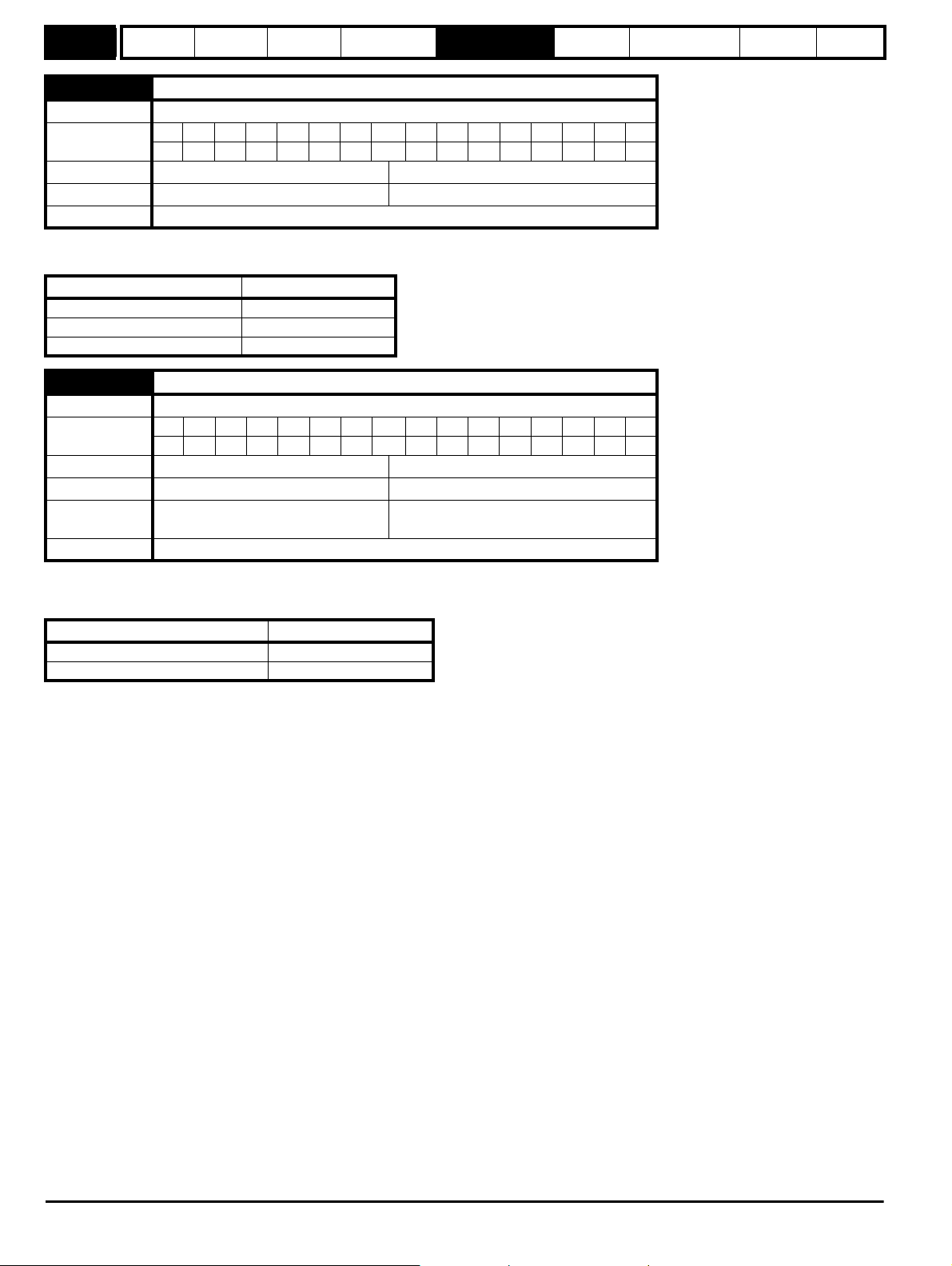
Menu 5
Parameter
structure
Keypad and
display
Parameter
x.00
Parameter
description format
Advanced parameter
descriptions
PC comms
protocol
Building automation
network
Performance RFC mode
5.15 Low frequency voltage boost
Drive modes Open-loop, RFC
Coding
Bit SP FI DE Txt VM DP ND RA NC NV PT US RW BU PS
1111
Range Open-loop, RFC 0.0 to 25.0 % of motor rated voltage
Default Open-loop, RFC See below
Update rate Background read
Voltage boost is used in fixed boost mode and square law mode for Open-loop mode, and also during the rotating auto-tune test in RFC mode. In
open-loop mode, the default is dependant on the frame size as given in the table below.
Drive sizes Default
BA1xxx, BA2xxx, BA3xxx 3.0%
BA4xxx, BA5xxx 2.0%
BA6xxx, BAMxxxx 1.0%
5.17 Stator resistance
Drive modes Open-loop, RFC
Coding
Bit SP FI DE Txt VM DP ND RA NC NV PT US RW BU PS
31 111
Range Open-loop, RFC 0.0 to 65.000
Default Open-loop, RFC 0.00
Second motor
parameter
Open-loop, RFC Pr 21.12
Update rate Background read
Pr 5.17 shows the stator resistance of the motor. The units vary with the drive size to ensure that the full range of likely resistances can be
represented with suitable resolution. The table below shows the units. Therefore 1.000 in the parameter represents the resistance shown in the units
column.
Drive size Units
BA1xxx to BA5xxx 1 Ohm
BA6xxx, BAMxxxx 0.01 Ohms
88 Affinity Advanced User Guide
Issue Number: 3
Page 89

Parameter
structure
Keypad and
display
Parameter
x.00
Parameter
description format
Advanced parameter
descriptions
PC comms
protocol
Building automation
network
5.18 Maximum switching frequency
Drive modes Open-loop, RFC
Coding
Bit SP FI DE Txt VM DP ND RA NC NV PT US RW BU PS
1 1 111
Range Open-loop, RFC 0 to 5 (3, 4, 6, 8, 12, 16 kHz)*
Default Open-loop, RFC 0 (3 kHz)
Update rate Background read
*The maximum switching frequency available is limited for some drive sizes as shown inTable 5-6 below.
Table 5-6 maximum switching frequency
200V kHz 400V kHz 575V kHz 690V kHz
BA1201 16 BA1401 16 BA3501 8 BA4601 8
BA1202 16 BA1402 16 BA3502 8 BA4602 8
BA1203 16 BA1403 16 BA3503 8 BA4603 8
BA1204 16 BA1404 16 BA3504 8 BA4604 8
BA2201 16 BA1405 16 BA3505 8 BA4605 8
BA2202 16 BA1406 16 BA3506 8 BA4606 8
BA2203 16 BA2401 16 BA3507 8 BA5601 8
BA3201 12 BA2402 16
BA3202 12 BA2403 16
BA4201 8 BA3401 16
BA4202 8 BA3402 16
BA4203 8 BA3403 12
BA5201 8 BA4401 8
BA5202 8 BA4402 8
BAMD12X1 6 BA4403 8
BAMD12X2 6 BA5401 8
BA5602 8
BA6601 6
BA6602 6
BAMA16X1 6
BAMA16X2 6
BAMD16X1 6
BAMD16X2 6
BAMD16X3 6
BAMD16X4 6
BAMD12X3 6 BA5402 8
BAMD12X4 6 BA6401 6
BA6402 6
BAMA14X1 6
BAMA14X2 6
BAMD14X1 6
BAMD14X2 6
BAMD14X3 6
BAMD14X4 6
Performance RFC mode
Menu 5
This parameter defines the required switching frequency. The drive may automatically reduce the actual switching frequency (without changing this
parameter) if the power stage becomes too hot. The switching frequency can reduce from 12kHz to 6kHz to 3kHz, or 16kHz to 8kHz to 4kHz. An
estimate of the IGBT junction temperature is made, based on the heatsink temperature and an instantaneous temperature drop using the drive output
current and switching frequency.
The estimated IGBT junction temperature is displayed in Pr 7.34. If the temperature exceeds 135°C, the switching frequency is reduced (if this is
possible i.e >4kHz) and this mode is enabled (see Pr 5.35 on page 94).
Reducing the switching frequency reduces the drive losses and the junction temperature displayed in Pr 7.34 also reduces. If the load condition
persists the junction temperature may continue to rise. If the temperature exceeds 145°C and the switching frequency cannot be reduced, the drive
will initiate an O.ht1 trip. Every 20ms the drive will attempt to restore the switching frequency if the higher switching frequency will not take the IGBT
temperature above 135°C.
The following table gives the sampling rate for different sections of the control system for different switching frequencies.
3, 6, 12kHz 4, 8, 16kHz Open-loop RFC
3 = 167s
Level 1
6 = 83s
125s Peak limit Current controllers
12 = 83s
Level 2 250s 250s
Current limit and
ramps
Speed controller
and ramps
Level 3 1ms 1ms Voltage controller
Level 4 4ms 4ms Time critical user interface
Background N/A N/A Non-time critical user interface
Affinity Advanced User Guide 89
Issue Number: 3
Page 90

Menu 5
Parameter
structure
Keypad and
display
Parameter
x.00
Parameter
description format
Advanced parameter
descriptions
PC comms
protocol
Building automation
network
Performance RFC mode
5.19 High stability space vector modulation
Drive modes Open-loop
Coding
Bit SP FI DE Txt VM DP ND RA NC NV PT US RW BU PS
111
Default Open-loop, 0
Update rate Background read
Normally the drive will use space vector modulation to produce the IGBT control signals. High stability space vector modulation offers three
advantages in an open loop drive, but the acoustic noise produced by the motor may increase slightly
.
• It is possible for instability to occur around motor rated frequency/2 on light load. The drive uses dead-time compensation to reduce this effect,
however it is still possible that some machines will be unstable. To prevent this, high stability space vector modulation should be enabled by
setting this parameter.
• As the output voltage approaches the maximum available from the drive pulse deletion occurs. This can cause unstable operation with a lightly or
fully loaded machine. High stability space vector modulation will reduce this effect.
• High stability space vector modulation also gives a small reduction in drive heat loss.
5.20 Quasi-square enable
Drive modes Open-loop
Coding
Bit SP FI DE Txt VM DP ND RA NC NV PT US RW BU PS
111
Default Open-loop 0
Update rate Background read
Open loop
The maximum modulation level of the drive is normally limited to unity, giving an output voltage equivalent to the drive input voltage minus voltage
drops within the drive. If the motor rated voltage is set at the same level as the supply voltage, some pulse deletion will occur as the drive output
voltage approaches the rated voltage level.
If Pr 5.20 is set to 1, the modulator will allow over modulation so that as the output frequency increases beyond the rated frequency, the voltage
continues to increase above the rated voltage. The modulation depth will increase beyond unity first producing trapezoidal and then quasi-square
waveforms. This can be used for example to obtain high output frequencies with a low switching frequency which would not be possible with space
vector modulation limited to unity modulation depth.
The disadvantage is that the machine current will be distorted as the modulation depth increases above unity, and will contain a significant amount of
low order odd harmonics of the fundamental output frequency.
As the rated voltage parameter is increased for a given DC bus voltage, the modulation depth is also increased. Therefore if the rated voltage is set to
a level higher than the supply voltage the point at which pulse dropping, over-modulation and quasi-square operation each begin, may occur at a
frequencies below the rated frequency.
5.21 Field gain reduction
Drive modes RFC
Coding
Bit SP FI DE Txt VM DP ND RA NC NV PT US RW BU PS
111
Default RFC 0
Update rate Background read
A suitable field controller gain is automatically set by the drive from the motor parameters. However by setting this parameter to 1, it is possible to
reduce this gain by a factor of 2 if instability problems occur above base speed.
5.23 Voltage offset
Drive modes Open-loop
Coding
Bit SP FI DE Txt VM DP ND RA NC NV PT US RW BU PS
1 1 111
Range Open-loop 0.0 to 25.0 V
Default Open-loop 0.0
Second motor
parameter
Open-loop Pr 21.13
Update rate Background read
Due to various effects in the drive inverter, a voltage offset must be produced before any current flows. To obtain good performance at low frequencies
where the machine terminal voltage is small, this offset must be taken into account. The value shown in Pr 5.23 is this offset given in line to line rms
volts. It is not possible for the user to measure this voltage easily, and so the automatic measurement procedure should be used (see Pr
5.14 on page 87).
90 Affinity Advanced User Guide
Issue Number: 3
Page 91

Parameter
R
1
jwL
1
jwL
2
R2/sjwL
m
Steady state per phase equivalent circuit
of an induction motor
structure
Keypad and
display
Parameter
x.00
Parameter
description format
Advanced parameter
descriptions
PC comms
protocol
Building automation
network
Performance RFC mode
Menu 5
5.24
Transient inductance (L
)
s
Drive modes Open-loop, RFC
Coding
Bit SP FI DE Txt VM DP ND RA NC NV PT US RW BU PS
31 111
Range Open-loop, RFC 0.000 to 500.000 mH
Default Open-loop, RFC 0.000
Second motor
parameter
Open-loop, RFC Pr 21.14
Update rate Background read
Open-loop, RFC
With reference to the diagram below, the transient inductance is defined as
L
= L1 + (L2.Lm / (L2 + Lm))
s
Based on the parameters normally used for the motor equivalent circuit for transient analysis, i.e. L
= L1 + Lm, Lr = L2 + Lm, the transient inductance
s
is given by
L
s
= Ls - (L
2
/ Lr)
m
The transient inductance is used as an intermediate variable to calculate the power factor in open-loop mode. It is used in the vector algorithm, for
cross-coupling compensation and to set the current controller gains in RFC mode.
5.25
Stator inductance (L
)
s
Drive modes RFC
Coding
Bit SP FI DE Txt VM DP ND RA NC NV PT US RW BU PS
2 1 111
Range RFC 0.00 to 5000.00 mH
Default RFC 0.00
Second motor
parameter
RFC Pr 21.24
Update rate Background read
This parameter holds the stator inductance of the motor with rated flux. If the motor flux is reduced, the value of stator inductance used by the vector
control algorithm is modified using the motor saturation breakpoints (Pr 5.29 and Pr 5.30). Stator inductance (L
) = L1 + Lm from the steady state
s
equivalent circuit. It should be noted that if this parameter is changed from a non-zero value to zero, the power factor (Pr 5.10) is automatically set to
0.850. The same applies to the motor map 2 stator inductance (Pr 21.24) and motor map 2 power factor (Pr 21.10).
5.26 High dynamic performance enable
Drive modes RFC
Coding
Bit SP FI DE Txt VM DP ND RA NC NV PT US RW BU PS
111
Default RFC 0
Update rate Background read
When this bit is set, the drive provides a cross-coupling feed forward voltage as produced by the transient inductance, and a frequency based voltage
feed forward term. These voltages improve the transient performance of the current controllers
Affinity Advanced User Guide 91
Issue Number: 3
Page 92

Menu 5
Parameter
structure
Keypad and
display
Parameter
x.00
Parameter
description format
Advanced parameter
descriptions
PC comms
protocol
Building automation
network
Performance RFC mode
5.27 Enable slip compensation
Drive modes Open-loop
Coding
Bit SP FI DE Txt VM DP ND RA NC NV PT US RW BU PS
1111
Default Open-loop 1
Update rate Background read
The level of slip compensation is set by the rated frequency and rated speed parameters. Slip compensation is only enabled when this parameter is
set to 1 Pr 5.08 is set to a value other than zero or synchronous speed.
5.28 Field weakening compensation disable
Drive modes RFC
Coding
Bit SP FI DE Txt VM DP ND RA NC NV PT US RW BU PS
111
Default RFC 0
Update rate Background read
When the flux in the motor is reduced below its rated level, the level of torque producing current required for a given amount of shaft torque is higher
than the rated level. In speed control the compensation prevents gain reduction at higher speeds. In torque control the compensation maintains the
torque at the correct level for a given torque demand. In some applications using speed control, it may be desirable to have a reduction of gain as the
motor flux is reduced to maintain stability. If this is required Pr 5.28 should be set to 1. It should be noted that although field weakening is possible in
servo mode, gain compensation is not applied in this mode.
5.29 Motor saturation breakpoint 1
Drive modes RFC
Coding
Bit SP FI DE Txt VM DP ND RA NC NV PT US RW BU PS
Range RFC 0 to 100 % of rated flux
Default RFC 50
Second motor
parameter
RFC Pr 21.25
Update rate Background read
111
92 Affinity Advanced User Guide
Issue Number: 3
Page 93

Parameter
i_mag (%)
flux (%)
50 75 100
100%
Pr
5.30
Pr
5.29
structure
Keypad and
display
Parameter
x.00
Parameter
description format
Advanced parameter
descriptions
PC comms
protocol
Building automation
network
Performance RFC mode
Menu 5
5.30 Motor saturation breakpoint 2
Drive modes RFC
Coding
Bit SP FI DE Txt VM DP ND RA NC NV PT US RW BU PS
111
Range RFC 0 to 100 % of rated flux
Default RFC 75
Second motor
parameter
RFC Pr 21.26
Update rate Background read
The rated level of flux in most induction motors causes saturation. Therefore the flux against flux producing current characteristic is non-linear. The
effects of saturation are to cause a step increase in torque when operating in torque mode, as the speed increases into the field weakening region.
The drive can include the effects of saturation by representing the flux producing current to flux characteristic as a series of three lines as shown
below:
If Pr 5.29 and Pr 5.30 have their default values of 50 and 75, the characteristic becomes one line and there will be a linear relationship between the
drive estimate of flux and the flux producing current. If Pr 5.29 and Pr 5.30 are increased above 50 and 75 the drive estimate of flux can include the
effect of saturation. It is unlikely that information will be available to set up these parameters, and so the values are determined during the rotating
auto-tune test.
5.31 Voltage controller gain
Drive modes Open-loop, RFC
Coding
Bit SP FI DE Txt VM DP ND RA NC NV PT US RW BU PS
111
Range Open-loop, RFC 0 to 30
Default Open-loop, RFC 1
Update rate Background read
This parameter controls the gain of the voltage controller used for mains loss and standard ramp control. If the parameter is set to 1, the gain used is
suitable for applications where the drive is used alone. Higher values are intended for applications where the DC bus of each drive is connected in
parallel, and the drive is used as a master for mains loss control. This is intended for use in applications where each drive is locked together using
open-loop frequency slaving. (If motors are locked together using digital-locking using a master for mains loss control, it is unlikely that the system will
be stable during mains loss unless the power rating of the master is much higher than the combined rating of the slaves. This is due to the lag created
by the master motor inertia.)
5.32 Motor torque per amp (Kt)
Drive modes RFC
Coding BitSPFIDETEVMDPNDRANCNVPTUSRWBUPS
RFC 21 1
Range RFC
0.00 to 500.00 NmA
-1
Update rate Background (1s) read
This parameter shows the motor torque per amp of active (torque producing) current used to calculate the speed controller gains when the automatic
set-up methods are active (i.e. Pr 3.17 = 1 or 2).
Affinity Advanced User Guide 93
Issue Number: 3
Page 94

Menu 5
Parameter
structure
Keypad and
display
Parameter
x.00
Parameter
description format
Advanced parameter
descriptions
PC comms
protocol
Building automation
network
Performance RFC mode
RFC
The drive calculates the motor torque per amp of active current using the motor parameters as shown below assuming a motor efficiency of 90%.
3 x Vrated x Irated x Rated power factor x Efficiency
Kt =
Rated speed (rad s
3 x Pr 5.09 x Pr 5.07 x Pr 5.10 x 0.9
Kt =
(2 x Pr 5.08 / 60) x Rated active current
-1
) x Rated active current
Rated active current is the active current when the motor current is equal to the rated motor current and is defined at the start of the description of
menu 4.
5.35 Disable auto-switching frequency change
Drive modes Open-loop, RFC
Coding
Bit SP FI DE Txt VM DP ND RA NC NV PT US RW BU PS
111
Default Open-loop, RFC 0
Update rate
Background read
The drive thermal protection scheme (see Pr 5.18 on page 89), reduces the switching frequency automatically when necessary to prevent the drive
from overheating. It is possible to disable this feature by setting this bit parameter to 1. If the feature is disabled, the drive trips immediately when the
IGBT temperature is too high.
5.37 Actual switching frequency
Drive modes Open-loop, RFC
Coding
Bit SP FI DE TE VM DP ND RA NC NV PT US RW BU PS
11111
Range Open-loop, RFC 0 to 7
Update rate
Background write
Pr 5.37 shows the actual switching frequency used by the inverter. The maximum switching frequency is set with parameter Pr 5.18, but this may be
reduced by the drive if automatic switching frequency changes are allowed (Pr 5.35=1). Pr 5.37 also indicates if the sample time for the current
controllers have been reduced to allow for RFC mode.
Value String Switching frequency Current controller Sample time
(kHz)
(s)
03 3 167
14 4 125
26 6 83
38 8 125
412 12 83
516 16 125
66 rEd 6 167
7 12 rEd 12 167
5.40 Spin start boost
Drive modes Open-loop, RFC
Coding
Bit SP FI DE TE VM DP ND RA NC NV PT US RW BU PS
1111
Range Open-loop, RFC 0.0 to 10.0
Default Open-loop, RFC 1.0
Update rate
Background read
If Pr 6.09 is set to enable the catch a spinning motor function in open-loop mode or RFC mode without position feedback (RFC mode) (Pr 3.24 = 1 or
3), this parameter will define a scaling function used by the algorithm which detects the speed of the motor.
It is likely that for smaller motors the default value of 1.0 is suitable, but for larger motors this parameter may need to be increased. If the value of this
parameter is too large, the motor may accelerate from standstill when the drive is enabled. If the value of this parameter is too small, the drive will
detect the motor speed as zero even if the motor is spinning.
94 Affinity Advanced User Guide
Issue Number: 3
Page 95

6.12
Keypad
STOP
1.11
Reference
enabled
indicator
1.12
Reverse
selected
indicator
1.13
Jog
selected
indicator
RUN
STOP/
RESET
FWD/REV
RESET
1.49
Reference
selected
indicator
Logic 1
Open loop only
6.06
Injection
braking level*
6.07
Injection
braking time*
6.17
Power
consumption
meter reset
6.21
Time
interval
between
filter changes
6.22
Filter
change
required/done
6.27
Electricity cost
per kWh
Clock control
Time before filter
change due
6.28
Running
cost
6.23
Power meter
Inverter enable
RFC only
Menu 2
Menu 3
Ramp
Hard speed
reference
enable
enable
5.03
Total motor
power
0.XX
0.XX
Key
Read-write
(RW)
parameter
Read-only (RO)
parameter
Input
terminals
Output
terminals
The parameters are all shown at their default settings
Pr = 4
1.49
01
Sequencer
6.01
6.03
6.08
6.09
6.40
Stop mode
*selector
Line power supply
loss mode**
Hold zero speed/
Motor pre-heat
*****enable
Catch a
spinning motor***
Enable sequencer
latching
5.05
DC bus voltage
Low voltage supply
Drive power supply monitor
6.44
Active supply
6.18
6.17
Time Day of
week
6.16
Date
6.19
Date/time
selector
0
1
2
3
4
5
Power up time
Slot 1 RTC
Slot 2 RTC
Internal RTC
Run time
Set time
6.25
6.26
Pr = 0
1.52
6.15
6.30
6.31
6.32
6.33
6.42
6.34
6.37
6.43
Jog reverse
Run
Forward / Reverse
Run reverse
Jog forward
Run forward
Drive enable
Control word
Control word
enable
6.35
6.36
Limit switch 2
Limit switch 1
6.29
Hardware
enable
Menu 8
6.04
Stop / Start
***select
T25 digital I/O 2
T26 digital I/O 3
T27 digital input 4
6.39
Not stop
Fire mode
active
0
1
1
0
0
0
0
0
0
0
0
0
Parameter
structure
Keypad and
display
Parameter
x.00
Parameter
description format
5.8 Menu 6: Sequencer and clock
Figure 5-9 Menu 6 logic diagram
Advanced parameter
descriptions
PC comms
protocol
Building automation
network
Performance RFC mode
Menu 6
Affinity Advanced User Guide 95
Issue Number: 3
Page 96

Menu 6
Parameter
structure
Keypad and
display
Parameter
x.00
Parameter
description format
Advanced parameter
descriptions
PC comms
protocol
Building automation
network
6.01 Stop mode
Drive modes Open-loop, RFC
Coding
Range
Default
BitSP FI DETEVMDPNDRANCNVPTUSRWBUPS
1 111
Open-loop
RFC
Open-loop,
RFC
0 to 5
0 to 2
1
1
Update rate Background read
Open-loop
Stopping is in two distinct phases: decelerating to stop, and stopped.
Stopping Mode Phase 1 Phase 2 Comments
0: Coast Inverter disabled
1: Ramp
2: Ramp followed by dc
injection
Ramp down to zero
frequency
Ramp down to zero
frequency
Low frequency current
3: dc injection with zero
speed detection
injection with detection of
low speed before next
phase.
4: Timed dc injection
braking stop
Inject dc at level specified
by Pr 6.06 for time specified
by Pr 6.07.
Drive cannot be re-enabled
for 1s
Wait for 1s with inverter
enabled
Inject dc at level specified by
Pr 6.06 for time defined by Pr
6.07
Inject dc at level specified by
Pr 6.06 for time defined by Pr
6.07
No phase 2.
5:Disable Inverter disabled No phase 2.
Delay in phase 2 allows rotor flux to decay.
The drive automatically senses low speed and therefore it
adjusts the injection time to suit the application. If the
injection current level is too small, the drive will not sense
low speed (normally a minimum of 50-60% is required).
Allows the drive to be immediately disabled and then reenabled again immediately if required.
Performance RFC mode
Once modes 3 or 4 have begun, the drive must go through the ready state before being restarted either by stopping, tripping or being disabled.
If this parameter is set to 5 (Disable stopping mode), the disable stopping mode is used when the run command is removed, and will allow the drive to
be started immediately by reapplying the run command. However, if the drive is disabled by removing the drive enable (i.e. via the secure disable
input or the drive enable (Pr 6.15), then the drive cannot be re-enabled for 1s.
RFC
Only one stopping phase exists, and the ready state is entered as soon as the single stopping action is complete. It should be noted that the stop
condition is detected when the speed feedback is below the zero speed threshold (Pr 3.05) for at least 16ms. If the speed is not stable, it is possible
that the stop condition may not be detected. In this case the system should be made more stable or alternatively the zero speed threshold should be
raised.
Stopping Mode Action
0: Coast Inhibits the inverter
1: Ramp Stop with ramp
2: No ramp Stop with no ramp
If coast stop is selected, the inverter is inhibited immediately when the run command is removed. If however hold zero speed is also selected (Pr 6.08
= 1), then the inverter will be re-enabled to hold zero speed. The result is that the inverter is disabled for one sample and then enabled to ramp the
motor to a stop. If coast stop is required Pr 6.08 should be set to zero to disable hold zero speed.
If stop with ramp is selected, the relevant ramp rate is used to stop the motor even if Pr 2.02 is set to zero to disable ramps.
The motor can be stopped with position orientation after stopping. This mode is selected with the position controller mode (Pr 13.10). When this mode
is selected Pr 6.01 has no effect.
96 Affinity Advanced User Guide
Issue Number: 3
Page 97
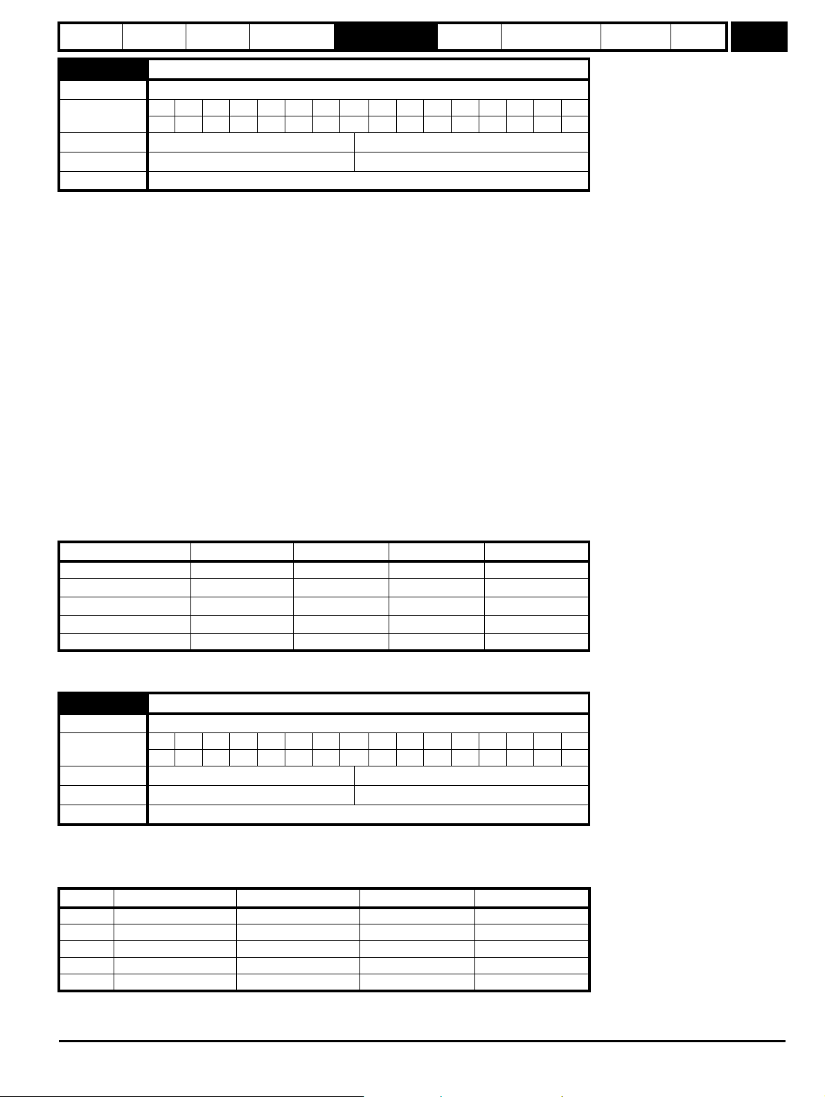
Parameter
structure
Keypad and
display
Parameter
x.00
Parameter
description format
Advanced parameter
descriptions
PC comms
protocol
Building automation
network
Performance RFC mode
Menu 6
6.03 Line power loss mode
Drive modes Open-loop, RFC
Coding
Bit SP FI DE TE VM DP ND RA NC NV PT US RW BU PS
1111
Range Open-loop, RFC 0 to 2
Default Open-loop, RFC 0
Update rate Background read
0: dis
There is no line power loss detection and the drive operates normally only as long as the DC bus voltage remains within specification (i.e. >Vuu).
Once the voltage falls below Vuu a UU trip occurs. This will reset itself if the voltage rises again above VuuRestart as shown in Table 5-7 Voltages and
voltage ratings on page 97.
1: Stop
Open-loop
The action taken by the drive is the same as for ride through mode except the ramp-down rate is at least as fast as the deceleration ramp setting, and
the drive will continue to decelerate and stop even if the line power is re-applied. If normal or timed injection braking is selected, the drive will use
ramp mode to stop on loss of line power. If ramp stop followed by injection braking is selected, the drive will ramp to a stop and then attempt to apply
dc injection. If the line supply is reapplied the drive restarts after it reaches the ready state provided the necessary controls are still active to initiate a
start.
RFC
The speed reference is set to zero and the ramps are disabled allowing the drive to decelerate the motor to a stop under current limit. If the line power
is re-applied while the motor is stopping, any run signal is ignored until the motor has stopped. If the current limit value is set at a very low level, the
drive may enter a UU trip before the motor has stopped. If the line power is reapplied the drive restarts after it reaches the ready state provided the
necessary controls are still active to initiate a start.
2: ride.th
The drive detects line power loss when the DC bus voltage falls below Vml
hold the DC bus level at Vml
force the DC bus voltage above the detection threshold Vml
. This causes the motor to decelerate at a rate that increases as the speed falls. If the line power is re-applied, it will
2
and the drive will continue to operate normally. The output of the line power loss
3
. The drive then enters a mode where a closed-loop controller attempts to
1
controller is a current demand that is fed into the current control system, and therefore the gain parameters Pr 4.13 and Pr 4.14 must be set up for
optimum control. See Pr 4.13 and Pr 4.14 on page 70 for set-up details.
Table 5-7 Voltages and voltage ratings
Voltage level 200V drive 400V drive 575V drive 690V drive
Vuu 175 350 500 500
Vml
Vml
Vml
1
2
3
205* 410* 540* 540*
Vml1 - 10V Vml1 - 20V Vml1 - 25V Vml1 - 25V
Vml1 + 10 Vml1 + 15 Vml1 + 50 Vml1 + 50
Vuu Restart 215 425 590 590
is defined by Pr 6.48. The values given in the table are the default values.
* Vml
1
6.04 Start/stop logic select
Drive modes Open-loop, RFC
Coding
Bit SP FI DE TE VM DP ND RA NC NV PT US RW BU PS
111
Range Open-loop, RFC 0 to 4
Default Open-loop, RFC 4
Update rate Background read
This parameter is provided to allow the user to select several predefined digital input routing macros to control the sequencer. When a value between
0 and 3 is selected the drive processor continuously updates the destination parameters for digital I/O T25, T26 and T27, and the enable sequencer
latching bit (Pr 6.40). When a value of 4 is selected the destination parameters for these digital I/O and Pr 6.40 can be modified by the user. (Note any
changes made to the destination parameters only become active after a drive reset.)
Pr 6.04 T25 (Pr 8.22) T26 (Pr 8.23) T27 (Pr 8.24) Pr 6.40
0Pr 6.29* Pr 6.30 Run Forward Pr 6.32 Run Reverse 0 (non latching)
1Pr 6.39 Not stop Pr 6.30 Run Forward Pr 6.32 Run Reverse 1 (latching)
2Pr 6.29* Pr 6.34 Run Pr 6.33 Fwd /Rev 0 (non latching)
3Pr 6.39 Not stop Pr 6.34 Run Pr 6.33 Fwd/Rev 1 (latching)
4 User prog User prog User prog User prog
* Pr 6.29 can be used as a fast disable parameter. See Pr 6.29 on page 103 for more information.
Affinity Advanced User Guide 97
Issue Number: 3
Page 98

Menu 6
CAUTION
Parameter
structure
Keypad and
display
Parameter
x.00
Parameter
description format
Advanced parameter
descriptions
PC comms
protocol
Building automation
network
Performance RFC mode
6.06 Injection braking level
Drive modes Open-loop
Coding
Bit SP FI DE TE VM DP ND RA NC NV PT US RW BU PS
1 1 111
Range Open-loop 0 to 150.0 %
Default Open-loop 100.0 %
Update rate Background read
Defines the current level used during dc injection braking as a percentage of motor rated current as defined by Pr 5.07.
6.07 Injection braking time
Drive modes Open-loop
Coding
Bit SP FI DETEVMDPNDRANCNVPTUSRWBUPS
1 111
Range Open-loop 0.0 to 25.0 s
Default Open-loop 1.0
Update rate Background read
Defines the time of injection braking during phase 1 with stopping modes 3 and 4 (see Pr 6.01 on page 96) for injection braking stop.
6.08 Hold zero speed / Motor pre-heat enable
Drive modes Open-loop, RFC
Coding
Bit SP FI DE TE VM DP ND RA NC NV PT US RW BU PS
111
Default Open-loop, RFC 0
Update rate Background read
Pre-heat mode is enabled if Pr 6.08 is set to a 1 and Pr 6.52 is set to a value greater than zero. When the run command is removed and the motor has
reached standstill, the drive applies a percentage (determined by the value in Pr 6.52) of the motor rated current. When pre-heat is active, then the
keypad displays the status "Heat".
Hold zero speed is enabled if Pr 6.08 is set to a one and Pr 6.52 is set to zero. When the run command is removed and the motor has reached
standstill, the drive continues to apply the magnetizing current. The level of magnetizing current cannot be modified. When hold zero speed is active,
then the keypad displays the status "StoP".
The drive cannot be switched between hold zero speed and pre-heat mode if any one of these modes is active. The drive should either be disabled or
running in order to change the mode.
The value in Pr 6.52 should not be set too high because it
could damage the motor or cause the motor thermal
protection to operate and trip the drive.
6.09 Catch a spinning motor
Drive modes Open-loop, RFC
Coding
Range
Default
BitSP FI DETEVMDPNDRANCNVPTUSRWBUPS
111
Open-loop
RFC
Open-loop
RFC
3
1
0
1
Update rate Background read
Open-loop
When the drive is enabled with this parameter at zero, the output frequency starts at zero and ramps to the required reference. When the drive is
enabled with this parameter at a non-zero value, the drive performs a start-up test to determine the motor speed and then sets the initial output
frequency to the synchronous frequency of the motor.
The test is not carried out and the motor frequency starts at zero:-
• if the run command is given when the drive is in the stop state.
• OR when the drive is first enabled after power-up with Ur_I voltage mode.
• OR when the run command is given with Ur_S voltage mode.
98 Affinity Advanced User Guide
Issue Number: 3
Page 99
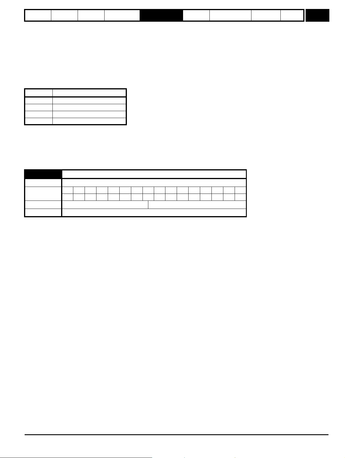
Parameter
structure
Keypad and
display
Parameter
x.00
Parameter
description format
Advanced parameter
descriptions
PC comms
protocol
Building automation
network
Performance RFC mode
Menu 6
Using the default parameters, the length of the test is approximately 200ms. However if the motor has a short rotor time constant/filter (usually found
in smaller motors) the time may be shorter. The drive will set the test time automatically if the motor parameters including the rated load rpm, are set
up correctly for the motor.
For the test to operate correctly, it is important that the stator resistance (Pr 5.17, Pr 21.12) is set up correctly. This applies even if fixed boost (Fd) or
square law (SrE) voltage mode is being used. The test uses the rated magnetizing current of the motor during the test, therefore the rated current
(Pr 5.07, Pr 21.07 and Pr 5.10, Pr 21.10) and power factor should be set to values close to those of the motor, although these parameters are not as
critical as the stator resistance. For larger motors, it may be necessary to increase Pr 5.40 (spin start boost) from its default value of 1.0 for the drive
to successfully detect the motor speed.
It should be noted that a stationary lightly loaded motor with low inertia may move slightly during the test. The direction of the movement is undefined.
Restrictions may be placed on the direction of this movement and on the frequencies detected by the drive as follows:
Pr 6.09 Function
0 Disabled
1 Detect all frequencies
2 Detect positive frequencies only
3 Detect negative frequencies only
RFC
When the drive is enabled with this bit at zero, the post ramp reference (Pr 2.01) starts at zero and ramps to the required reference. When the drive is
enabled with this parameter at one, the post ramp reference is set to the motor speed. When RFC mode is used feedback and catch a spinning motor
is not required, this parameter should be set to zero as this avoids unwanted movement of the motor shaft when zero speed is required. When RFC
mode is used with larger motors, it may be necessary to increase Pr 5.40 (spin start boost) from its default value of 1.0 for the drive to successfully
detect the motor speed.
6.12 Enable stop key
Drive modes Open-loop, RFC
Coding
Bit SP FI DE TE VM DP ND RA NC NV PT US RW BU PS
111
Default Open-loop, RFC 0
Update rate Background read
This parameter permanently enables the Stop key on the drive such that the drive will always stop when the Stop key is pressed. If keypad mode is
selected this has no effect because the Stop key is automatically enabled.
The sequencer logic has been designed so that pressing the Stop key (whether the Stop key is enabled or not), does not make the drive change from
a stopped to a running condition. As the Stop key is also used to reset trips, this means that if the Stop key is pressed when the drive is tripped, the
trip will be reset but the drive does not start. (This does not apply to the UU trip which cannot be reset by the user, but is automatically reset when the
DC bus voltage is high enough).
Preventing the drive from starting when the stop key is pressed is implemented as follows:-
Sequencer latching not enabled (Pr 6.40=0)
If the Stop key is pressed when the Stop key is enabled (Pr 6.12=1), or when the drive is tripped the sequencer run is removed, and so the drive stops
or remains stopped respectively. The sequencer run can only then be reapplied after at least one of the following conditions occurs:-
1. Run forward, Run reverse and Run sequencing bits all zero
2. OR the drive is disabled via Pr 6.15 or Pr 6.29
3. OR Run forward and Run reverse are both active and have been for 60ms.
4. OR The drive is in the UU state.
The drive can then be restarted by activating the necessary bits to give a normal start.
Sequencer latching enabled (Pr 6.40=1)
If the Stop key is pressed when the stop key is enabled (Pr 6.12=1) or when the drive is tripped the sequencer run is removed, and so the drive stops
or remains stopped respectively. The sequencer run can only then be reapplied after at least one of the following conditions occurs.
1. Run forward, Run reverse and Run sequencing bits all zero after the latches
2. OR Not stop sequencing bit is zero
3. OR the drive is disabled via Pr 6.15 or Pr 6.29
4. OR Run forward and Run reverse are both active and have been for 60ms.
5. OR The drive is in the UU state.
The drive can then be restarted by activating the necessary bits to give a normal start. Note that Run forward and Run reverse
together will reset the
stop key condition, but the latches associated with Run forward and Run reverse must then be reset before the drive can be restarted. It should be
noted that holding the Run key and pressing the Stop key to reset the drive without stopping does not apply unless keypad reference mode is
selected.
Affinity Advanced User Guide 99
Issue Number: 3
Page 100

Menu 6
Parameter
structure
Keypad and
display
Parameter
x.00
Parameter
description format
Advanced parameter
descriptions
6.15 Drive enable
Drive modes Open-loop, RFC
Coding
Bit SP FI DETEVMDPNDRANCNVPTUSRWBUPS
1 111
Default Open-loop, RFC 1
Update rate 4ms read
Setting this parameter to 0 will disable the drive. It must be at 1 for the drive to run.
6.16 Date
Drive modes Open-loop, RFC
Coding
Bit SP FI DETEVMDPNDRANCNVPTUSRWBUPS
11111
Default Open-loop, RFC 0 to 311299
Update rate Background read/write
6.17 Time
Drive modes Open-loop, RFC
Coding
Bit SP FI DETEVMDPNDRANCNVPTUSRWBUPS
21 1 1 11
Default Open-loop, RFC 0.0 to 23.59
Update rate Background read/write
PC comms
protocol
Building automation
network
Performance RFC mode
6.18 Day of week
Drive modes Open-loop, RFC
Coding
Bit SP FI DETEVMDPNDRANCNVPTUSRWBUPS
111 1
Default Open-loop, RFC 0 to 6
Update rate Background write
6.19 Date / Time selector
Drive modes Open-loop, RFC
Coding
Bit SP FI DETEVMDPNDRANCNVPTUSRWBUPS
Range Open-loop, RFC 0 to 5
Default Open-loop, RFC 3
Update rate Background read
111
100 Affinity Advanced User Guide
Issue Number: 3
 Loading...