

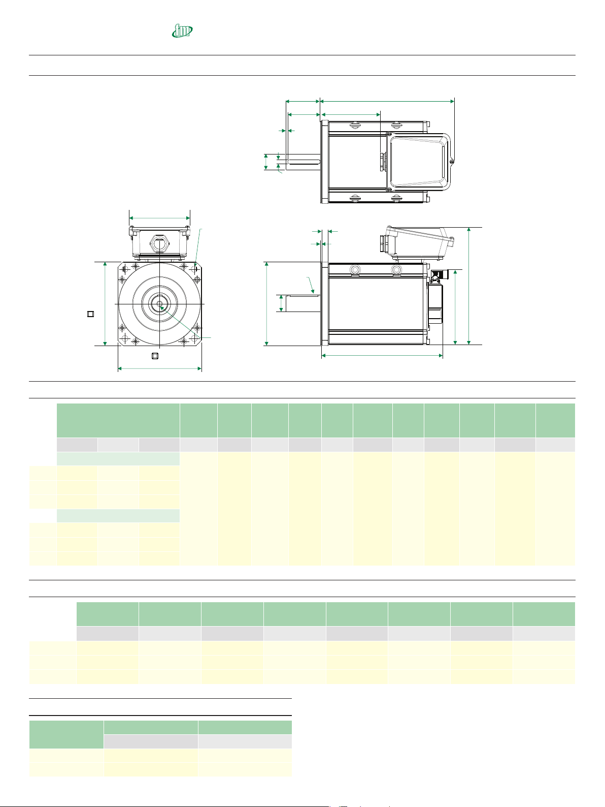
Dimensions (mm) Frame size 250
NOTE: Output key dimensions
(E,F,G and H) are applicable
to keyed units only.
D
F
G
E
Optional
key
4 holes ∅R (H14)
equispaced on a
mounting PCD ∅S
P
Motor flange
T
Motor housing
Tapped hole
thread size
I to depth J
K Flange
L max
A max
N
V
U
For vertical
connectors,
allow
appr oximately
300.0mm
clearance for
mating cable
H (h9)
∅C (k6)
∅M (j6)
B 1
A1
Standard motor dimension (mm) Note all dimensions shown are at nominal
Motor Length
Flange
thickness
Register
length
Register
diameter
Overall
height
Flange
square
Fixing
hole
diameter
Fixing
hole
PCD
Motor
housing
Hybrid
box
width
Signal
connector
height
Mounting
bolts
A
(± 1.3) A1 (± 2.0) B1 (± 1.3) K (± 0.5) L (± 0.1) M (j6) N (± 1.0) P (± 0.6) R (H14) S (± 0.4) T (± 1.0) U (± 0.4) V (± 1.0)
Unbraked motor
20.0 4.50 250.0 362.8 256.0 18.5 300.0 249.5 186.0 228.5 M16
250D
370.7 406.1 179.7
250E
400.7 436.1 209.7
250F
430.7 466.1 239.7
Braked motor
250D
442.5 477.9 251.5
250E
472.5 507.9 281.5
250F
502.5 537.9 311.5
Output shaft dimensions (mm)
Shaft
diameter
Shaft
length
Key height
Key
length
Key to shaft end
Key
width
Tapped hole
thread size
Tapped hole
depth
C
(k6) D (± 0.45) E (± 0.4) F (± 0.25) G (± 1.1) H (h9) I J (± 0.4)
38.0 Opt
38.0 80.0 41.0 70.0 4.6 10.0 M12x1.75 29.0
42.0 Opt
42.0 110.0 45.0 100.0 6.0 12.0 M16x2.0 37.0
48.0 D-F Std
48.0 110.0 51.5 100.0 6.0 14.0 M16x2.0 37.0
18
www.controltechniques.com
055-250 Unimotor Product Data
Optional connector height (mm)
Connection type
Power overall height Signal overall height
N
(± 1.0) V (± 1.0)
V
291.5 221.0
C
312.5 221.0
 Loading...