

Control Techniques Unidrive M100, Unidrive M200, Unidrive M101, Unidrive M201, Unidrive M300 Step-by-step Manual
Page 1
Unidrive M100/M101/M200/
M201/M300
Step By Step Guide
Guide pas à pas
Schritt-für-Schritt-Anleitung
Guida dettagliata
Guía detallada
Frame sizes 1 to 4
Tailles 1 à 4
Baugrößen 1 bis 4
Taglie da 1 a 4
Tamaños 1 a 4
www.drive-setup.com
EN
FR
DE
IT
ES
Page 2 Page 10 Seite 18 Pagina 26
Página 34
This guide provides a fast and simple start-up procedure for a basic drive and motor installation.
For help with more advanced installations: Comprehensive user guides, online videos and help tools can be
accessed using the web address or QR code above.
Please read the safety information booklet supplied with the drive before installation or set-up.
For M300, it is essential to read Section 4.6 in the Quick Start Guide using the web address or QR code
above prior to using the Safe Torque Off function in safety systems.
Diese Anleitung bietet Informationen für eine schnelle Inbetriebnahme eines einfachen Umrichter-Motor-Systems.
Bei aufwendigeren Systemen: Umfassende Betriebsanleitungen, Online-Videos und Hilfsmittel finden Sie unter
unserer Webadresse oder über den vorstehenden QR-Code.
Bitte lesen Sie die dem Umrichter beiliegende Sicherheitsdokumentation, bevor Sie den Umrichter montieren
oder in Betrieb nehmen. Beim M300 ist unbedingt Abschnitt 4.6 in der Kurzanleitung über die Web-Adresse
bzw. den vorstehenden QR-Code hinzuzuziehen, um die Safe Torque Off-Funktion in Sicherheitssystemen
zu verwenden.
Esta guía contiene un procedimiento inicial rápido y sencillo de la instalación básica de accionamiento y motor.
Para obtener ayuda sobre instalaciones más avanzadas: es posible acceder a guías de usuario, herramientas de
ayuda y vídeos online exhaustivos mediante la dirección en Internet o el código QR anterior.
Lea el folleto de información de seguridad suministrado con el accionamiento antes de llevar a cabo la instalación
o la configuración. Para el accionamiento M300, es imprescindible consultar la Sección 4.6 de la Guía de
consulta rápida mediante la dirección en Internet o el código QR anterior antes de utilizar la función Safe Torque
Off en los sistemas de seguridad.
Questa guida fornisce una procedura di avviamento semplice e veloce per l'installazione di un azionamento base e del motore.
Chi avesse bisogno di un supporto per l'installazione di soluzioni più avanzate può consultare le guide complete per l'utente,
i video online e gli strumenti di supporto, a cui può accedere utilizzando l'indirizzo Internet o il codice QR qui sopra.
Prima di procedere con l'installazione o la configurazione leggere l'opuscolo contenente le informazioni per la
sicurezza fornito a corredo dell'azionamento. Per il modello M300 è fondamentale consultare la Sezione 4.6 della
Guida introduttiva utilizzando l'indirizzo Internet o il codice QR qui sopra prima di utilizzare la funzione Safe Torque
Off nei sistemi di sicurezza.
Ce guide fournit des instructions d'installation et de démarrage simples et rapides d’un variateur.
Pour des informations complémentaires sur des installations moins basiques : des guides de mise en service complets,
des vidéos et des outils d’aide en ligne sont accessibles en utilisant l’adresse Web ou le QR code ci-dessus.
Lire attentivement le livret d’informations relatives à la sécurité fourni avec le variateur avant de procéder à
l’installation ou à la configuration. Pour l’Unidrive M300, il est essentiel de consulter la section 4.6 du Guide de
mise en service rapide accessible en utilisant l’adresse Web ou le QR code ci-dessus avant d’utiliser la
fonction Absence sûre du couple dans les systèmes de sécurité.
Page 2
2 Unidrive M100/M101/M200/M201/M300 Step By Step Guide
Issue Number: 1
English
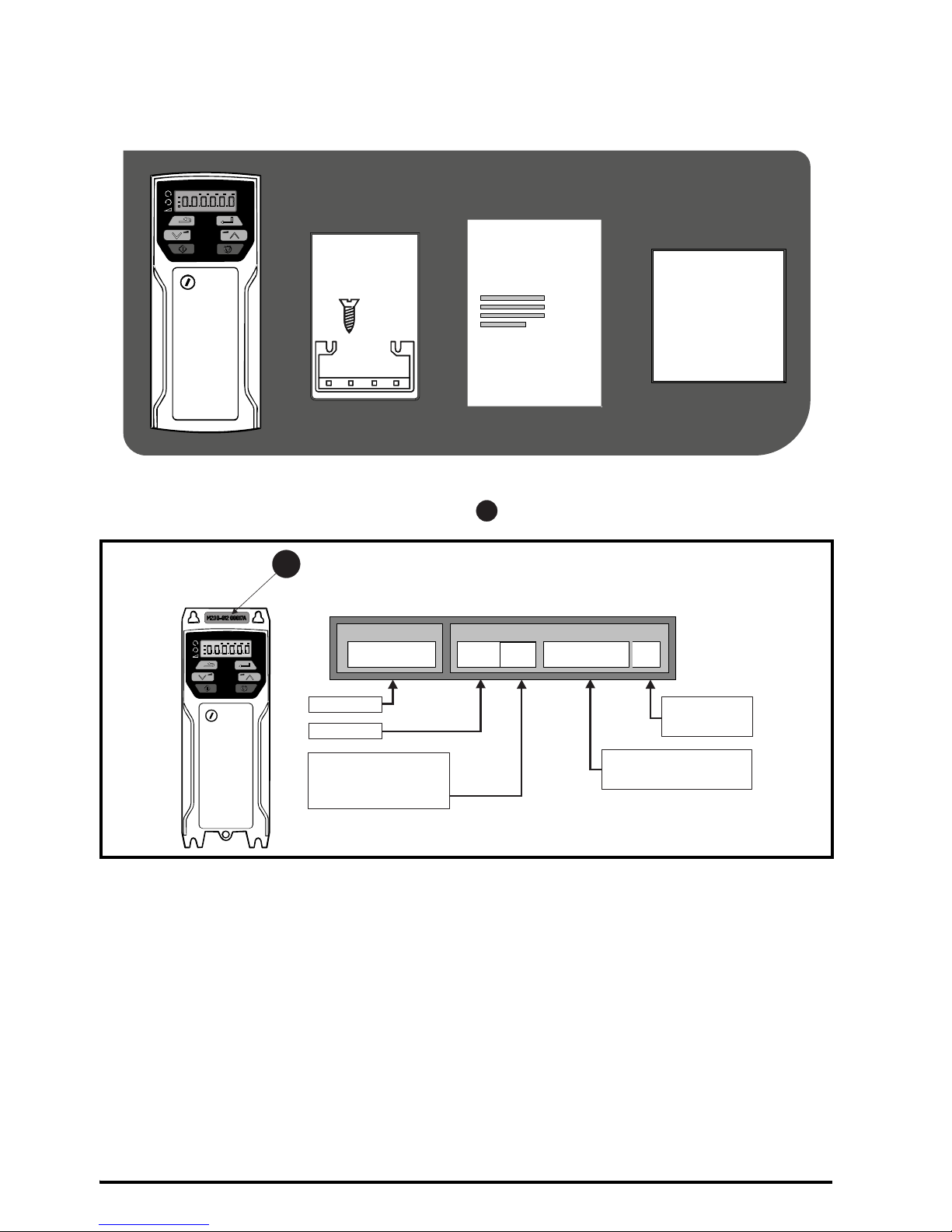
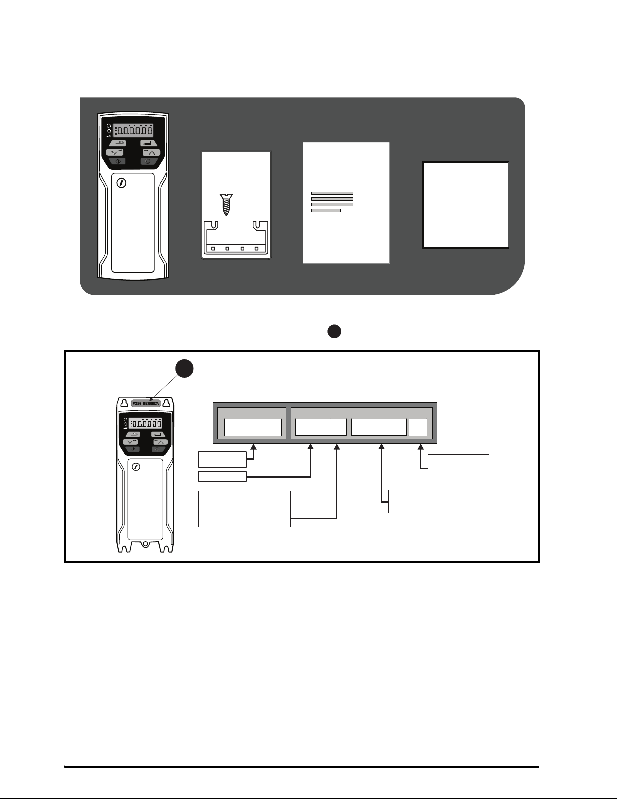
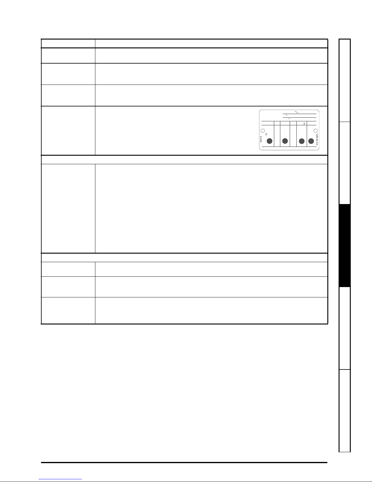
STEP 1: Check the contents of the box
Check you have all the components and your drive has not been damaged during transportation.
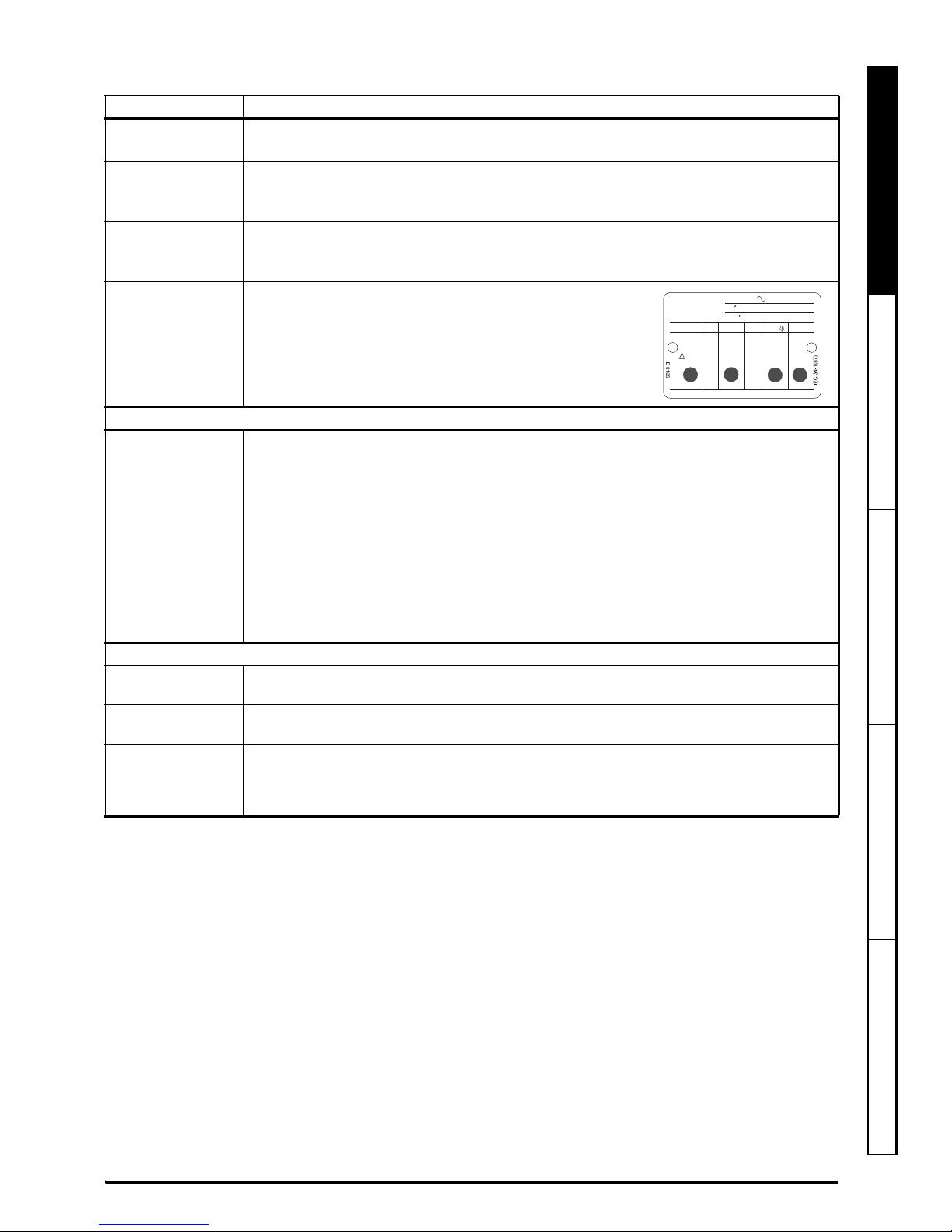
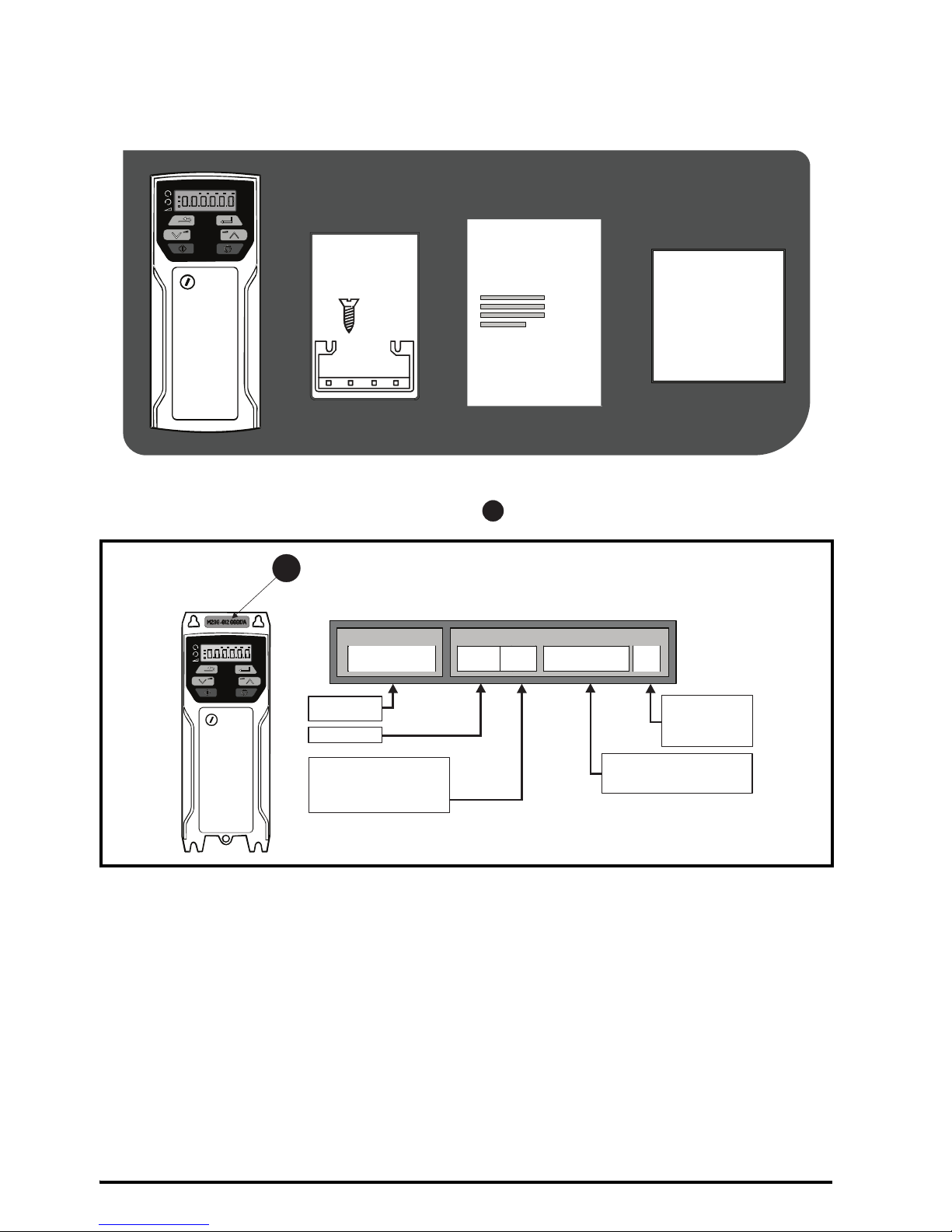
STEP 2: Check model and voltage
The model number can be found on the identification label on the top of the drive. Please check that the model
and the drive voltage range is suitable for the installation.
x4
KIT BAG
CABLE BRACKET
SAFETY
INFORMATION
++
+
STEP BY STEP GUIDE
1
Product line:
Frame size:
Current Rating :
Heavy Duty current rating x10
Drive Format :
A – AC in AC out
Voltage rating
:
1 - 100 V (100 - 120 ± 10 %)
2 - 200 V (200 - 240 ± 10 %)
4 - 400 V (380 - 480 ± 10 %)
Derivative
Electrical Specifications
M200 - 03 4 00073 A
1
Page 3
Unidrive M100/M101/M200/M201/M300 Step By Step Guide 3
Issue Number: 1
English
French German Italian Spanish
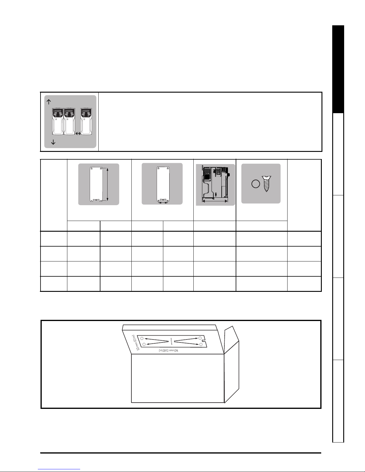
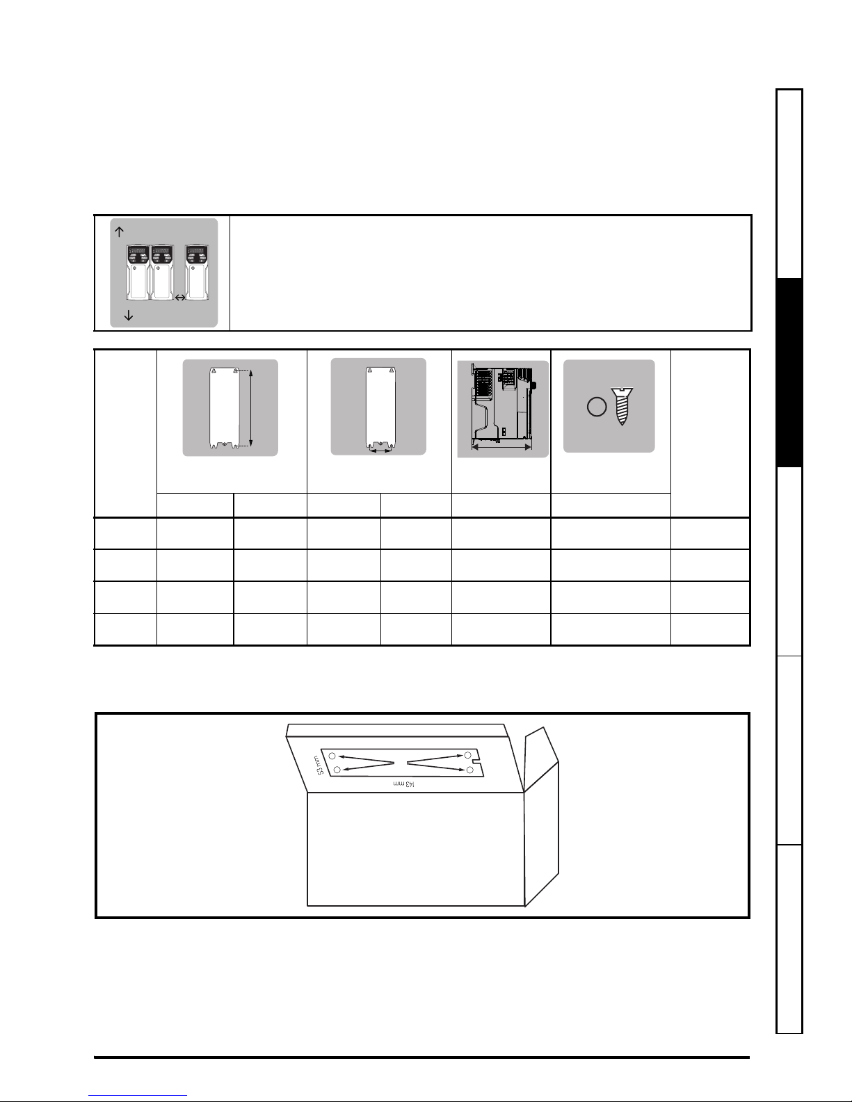
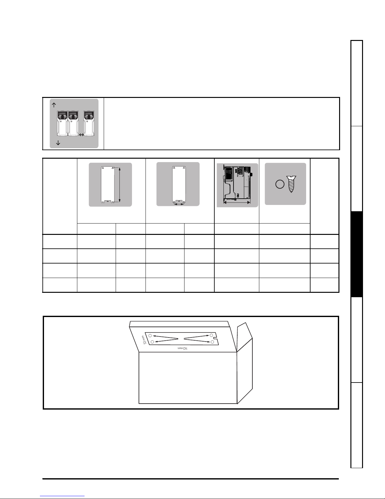
STEP 3: Mount the drive
Ambient temperature operating range:
- 20 °C to 60 °C (- 4 °F to 140 °F).
Output current derating may be required at ambient temperatures > 40 °C (104 °F). Refer to the Power Installation
Guide (section 5.1). For UL installations, the maximum ambient temperature permitted is 50 °C (104 °F) with any
specified derating applied.
Drives can be panel mounted with 0mm space between them. A minimum clearance of 100 mm (3.94 in)
is required above and below the drive. Refer to section 3.4 in the Power Installation Guide for information on
derating for reduced clearances.
* The Speed Ref Potentiometer adds an additional 11 mm (0.43 in) to the overall depth on a Unidrive M101 and
M201 only.
A Drill template for wall mounting is included on the drive packaging (shown below).
STEP 4: Fit cable ground bracket
The cable bracket helps you to organise the cables once they have been connected to the drive.The bracket is
used to clamp the shield of the cables to facilitate EMC compliance (refer to Figure 7-1).
Frame
Weight
HW
D
*
Ø
Mounting Overall Mounting Overall Overall Diameter
1
143 mm
(5.7 in)
160 mm
(6.3 in)
53 mm
(2.08 in)
75 mm
(2.95 in)
130 mm
(5.1 in)
5mm
(0.2 in)
0.75 kg
(1.65 Ib)
2
194 mm
(7.63 in)
205 mm
(8.07 in)
55 mm
(2.17 in)
75 mm
(2.95 in)
150 mm
(5.9 in)
5mm
(0.2 in)
1.3 kg
(3.0 Ib)
3
215 mm
(8.46 in)
226 mm
(8.9 in)
70.7 mm
(2.80 in)
90 mm
(3.54 in)
160 mm
(6.3 in)
5mm
(0.2 in)
1.5 kg
(3.3 Ib)
4
265 mm
(10.43 in)
277 mm
(10.9 in)
86 mm
(3.40 in)
115 mm
(4.5 in)
175 mm
(6.9 in)
6mm
(0.23 in)
3.13 kg
(6.9 Ib)
100 mm (3.94 in)
100 mm
(3.94 in)
0 mm
The Drive can be screwed onto a backplate or mounted on a DIN rail (size 1 and 2 only).
If you choose to mount it on a rail use 2 screws to secure the drive to the back plate.
+
+
+
+
Page 4
4 Unidrive M100/M101/M200/M201/M300 Step By Step Guide
Issue Number: 1
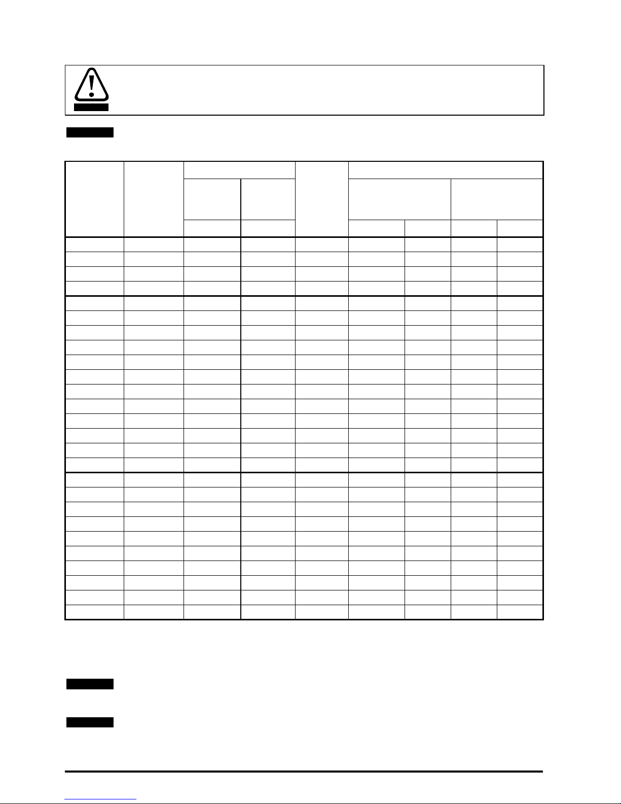
STEP 5: Select cables and fuses or MCB
* These fuses are fast acting.
** For UL installations, the circuit breaker must be Listed under category control number DIVQ / DIVQ7, rated
600 Vac with a short circuit rating > 10 kA. In other countries, circuit breakers compliant with EN IEC 60947-2 are
recommended, with > 10 kA short circuit breaking capacity
The voltage rating of fuses and MCBs must be greater than or equal to the highest supply voltage of
the system. Fuses: The AC supply to the drive must be installed with suitable protection against
overload. Failure to observe this requirement will cause risk of fire.
Ground conductor size:- Either 10 mm
2
or two conductors of the same cross-sectional area as the input
conductors.
Model
Input
Phases
Fuses
MCB
rating**
Cables
IEC Class
gG
UL
Class CC
J, or T
*
IEC60364-5-52
mm
2
UL 508C
AWG
A A Input Output Input Output
01100017 1 10 15 15 1 1 16 16
01100024 1 16 15 15 1.5 1 14 16
02100042 1 20 20 15 2.5 1 12 16
02100056 1 25 25 15 4 1 10 16
01200017 1 6 6 15 1 1 16 16
01200024 1 6 6 15 1 1 16 16
01200033 1 10 15 15 1 1 16 16
01200042 1 16 15 15 1 1 16 16
02200024 1 / 3 6/6 6/6 15 1 1 16 16
02200033 1 / 3 10/10 10/10 15 1 1 16 16
02200042 1 / 3 16/10 15/10 15 1 1 16 16
02200056 1 / 3 20/16 20/15 15 2.5/1.5 1 12/14 16
02200075 1 / 3 20/16 20/15 15 2.5 1 12 16
03200100 1 / 3 25/20 25/20 25/20 4 1.5 10/12 14
04200133 1 / 3 25/20 25/20 25/20 4/2.5 2.5 10 12
04200176 3 25 25 25 4 2.5 10 12
02400013 3 6 6 15 1 1 16 16
02400018 3 6 6 15 1 1 16 16
02400023 3 6 6 15 1 1 16 16
02400032 3 6 6 15 1 1 16 16
02400041 3 10 6 15 1 1 16 16
03400056 3 10 15 15 1 1 14 16
03400073 3 16 15 15 1.5 1 12 16
03400094 3 16 15 25 2.5 1.5 12 14
04400135 3 20 20 20 2.5 2.5 10 12
04400170 3 25 25 25 4 2.5 10 12
The product is UL listed for use on a circuit up to 100 kA maximum supply symmetrical fault current,
when protected by fuses.
IEC cable sizes assume Copper conductor, PVC insulation, Installation method B2 and ambient
temperature of 40 °C (104 °F). UL cable sizes assume Copper conductor with insulation rated at 75 °C
(167 °F).
WARNING
NOTE
NOTE
NOTE
Page 5
Unidrive M100/M101/M200/M201/M300 Step By Step Guide 5
Issue Number: 1
English
French German Italian Spanish
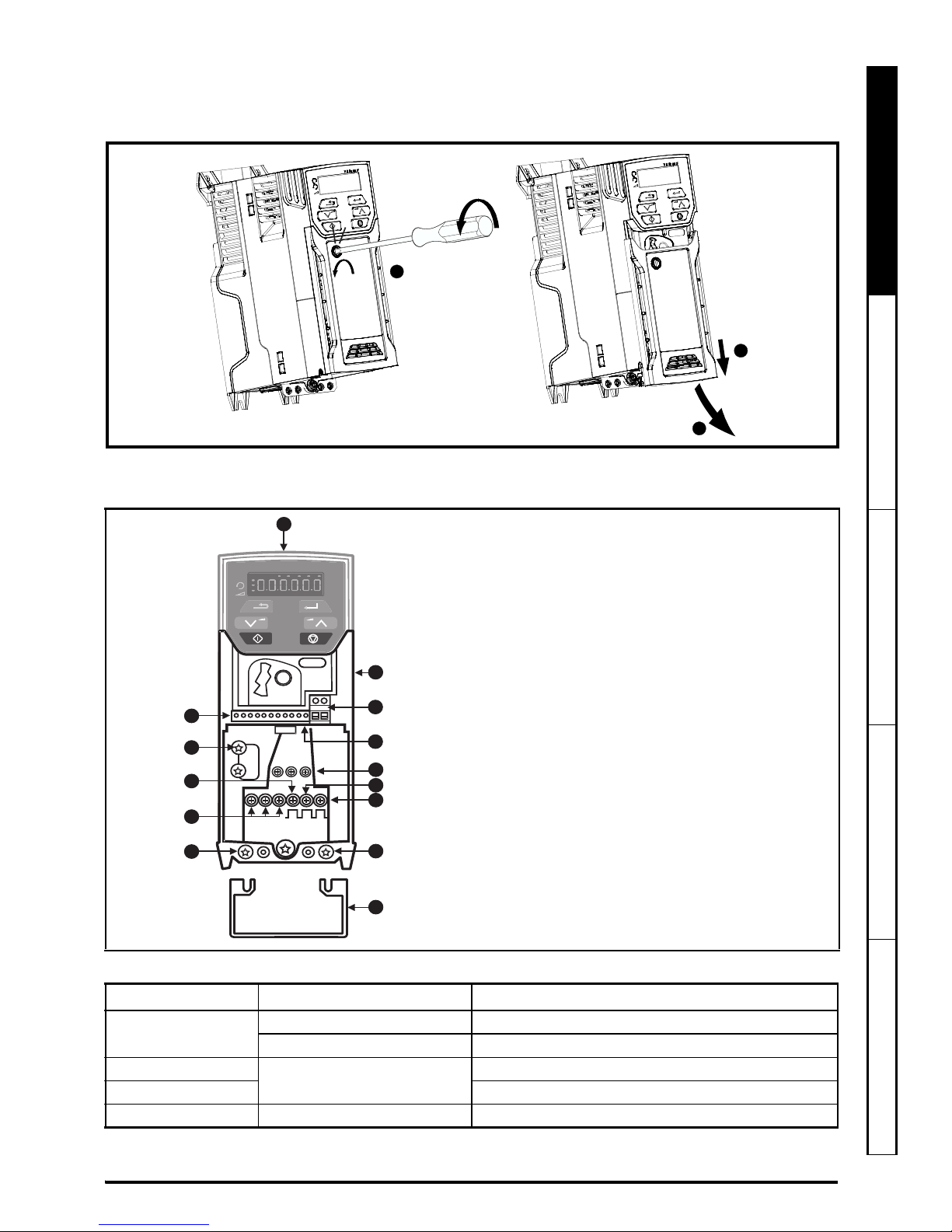
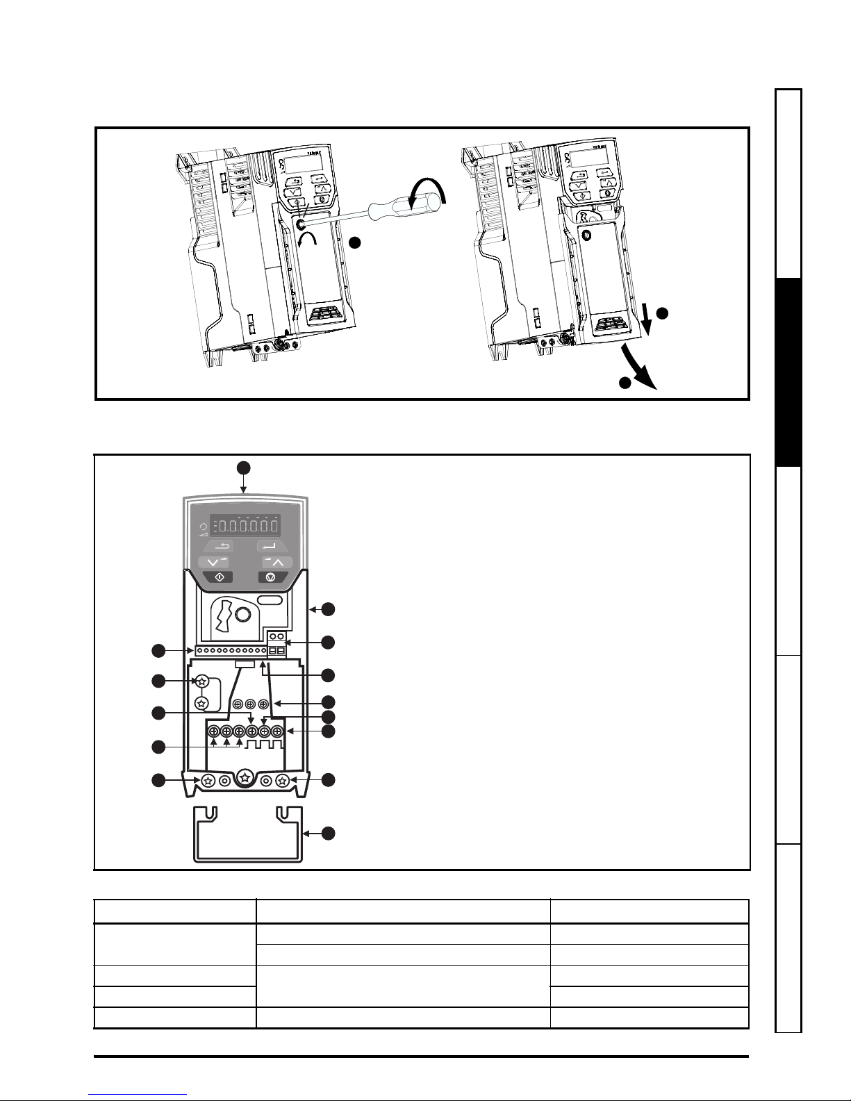
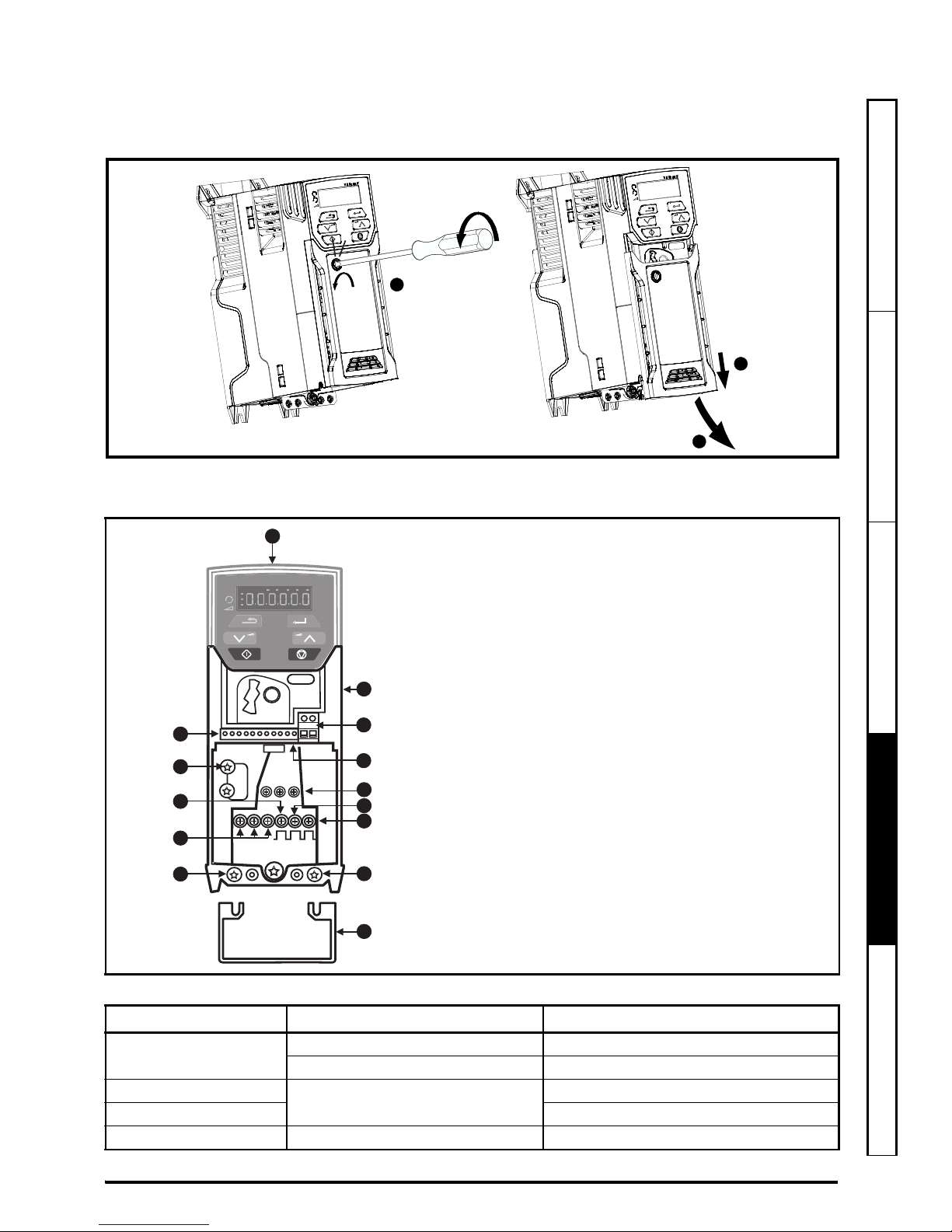
STEP 6: Remove the terminal cover
1. Using a flat bladed screwdriver, turn the terminal cover locking clip anti-clockwise by approximately 30°.
2. Slide the terminal cover down.
3. Remove terminal cover in direction shown.
STEP 7: Identify the features of the drive
Figure 7-1 Feature diagram (size 2 shown)
Table 7-1 Recommended torque settings
Model size Terminal block description Torque settings
All
Control terminals 0.2 N m (0.15 Ib ft)
Relay terminals 0.5 N m (0.37 Ib ft)
1
Power terminals
0.5 N m (0.37 Ib ft)
2, 3, 4 1.4 N m (1.03 Ib ft)
All Ground terminals 1.5 N m (1.10 Ib ft)
2
3
1
+
EMC
MOV
L1 L2 L3
U V W - + BR
2
1
3
12
10
7
5
11
11
9
8
6
4
13
Key
1. Rating label (on side of drive)
2. Identification label
3. Relay connections
4. Control connections
5. Braking terminal
6. Internal EMC filter screw*
7. DC bus +
8. DC bus -
9. Motor connections
10. AC supply connections
11. Ground connections
12. Safe Torque Off terminals (STO)**
13. Cable bracket to screw onto ground
terminals (11).
* Before removing the screw, refer to section 4.7.2
in the Power Installation Guide.
** Unidrive M300 only.
Page 6
6 Unidrive M100/M101/M200/M201/M300 Step By Step Guide
Issue Number: 1
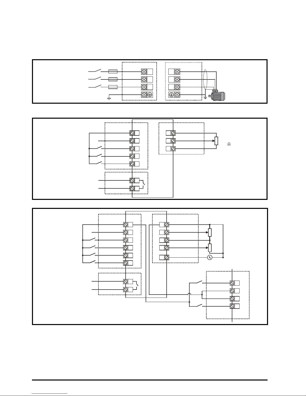
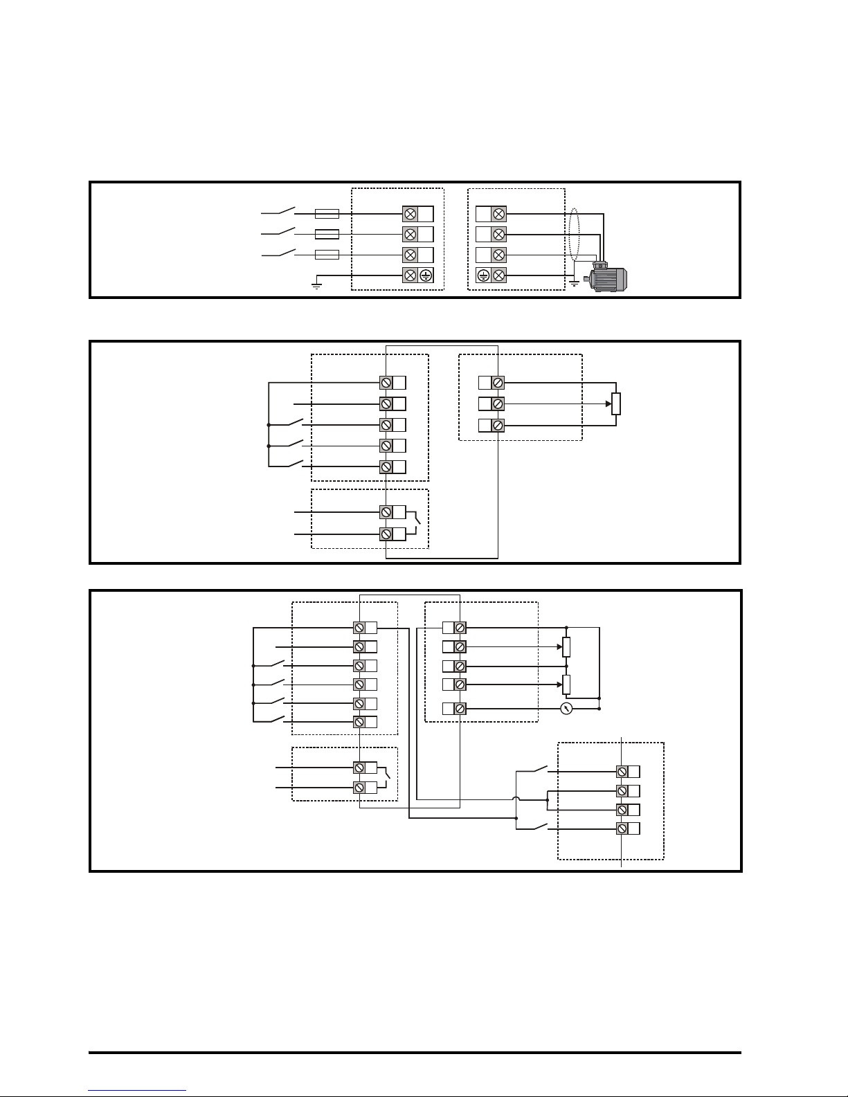
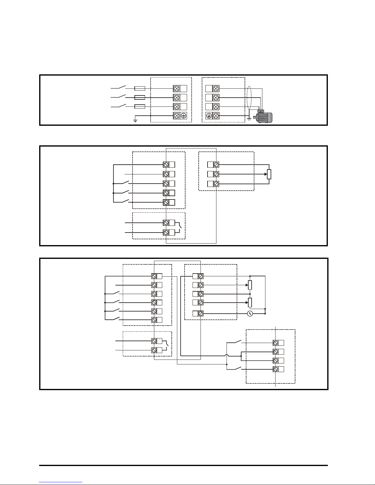
STEP 8: Wire the drive up
M100/M200/M300: The wiring diagram is for use with the default drive configuration (Pr 05 set to AV) which is
frequency control via Analog Input 1 (0-10 V) or Analog Input 2 (0-10 V) selected by terminal 14.
M101/M201: The default setting uses the onboard Speed Ref Potentiometer rather than the analog input for the
frequency reference (only the drive enable terminal is required).
Figure 8-1 Power terminal connections
* With a 1 ph supply, the supply should be connected to L1 and L3.
Figure 8-2 Unidrive M100/M101 control terminal connections
Figure 8-3 Unidrive M200/M201/M300 control terminal connections
** Not required on Unidrive M101 and M201 since the Speed Ref Potentiometer is already on the product. The Run/
Stop commands are given from the keypad and if reverse direction is needed, the user should set Pr 17 to On.
*** Unidrive M300 uses Safe Torque Off (drive enable) inputs and terminal 11 is unassigned.
**** 250 Vac maximum (UL class 1).
Refer to section 4.4 in the Quick Start Guide for information and wiring diagrams for alternative configurations.
An external braking resistor can be connected if required. Refer to section 4.5.1 in the Power Installation Guide
for further details.
L1
L2
L3
1 ph /3 ph*
AC power
supply
U
V
W
AC supply Motor
9
10
11
12
Zero frequency
Run forward**
13
Run reverse**
Digital I/O
1
2
4
0 V
Analog I/O
Analog input 1
10 V user
Frequency
reference
**
41
42
Drive ok
Relay****
Drive enable
Digital Input 2
24 V user
Digital I/O1
Digital input 3
Digital input 4
10 k
W
Drive enable***
9
10
11
12
Zero frequency
Run forward**
13
Run reverse**
14
Digital I/O
Analog input 1/
Analog input 2 select
Digital Input 2
24 V user
Digital I/O1
Digital input 3
Digital input 4
Digital input 5
41
42
Drive ok
Relay 1****
1
2
0V
Analog I/O
Analog input 1
7
Analog output 1
4
10 V user
5
Analog input 2
Frequency
reference 1
**
Frequency
reference 2**
Frequency output
10 kW
10 kW
34
33
31
32
S01T
0V
STO1
0V
STO2
S02T
M300 only
Safe Torque
Off
0V
0V
24 V user
Page 7
Unidrive M100/M101/M200/M201/M300 Step By Step Guide 7
Issue Number: 1
English
French German Italian Spanish
STEP 9: Power up the drive
• Ensure the drive enable signal is not given, terminal 11 (or terminal 31 and 34 on Unidrive M300) is open.
• Ensure the run signal is not given, terminal 12 and 13 are open (Unidrive M100, M200 and M300).
• Ensure the motor is connected to the drive.
• Ensure the motor connection (Δ or Y) is correct.
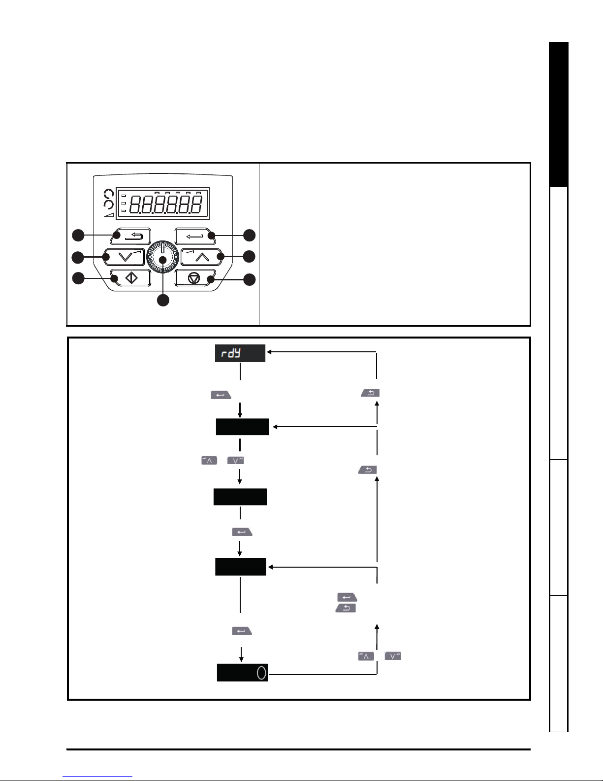
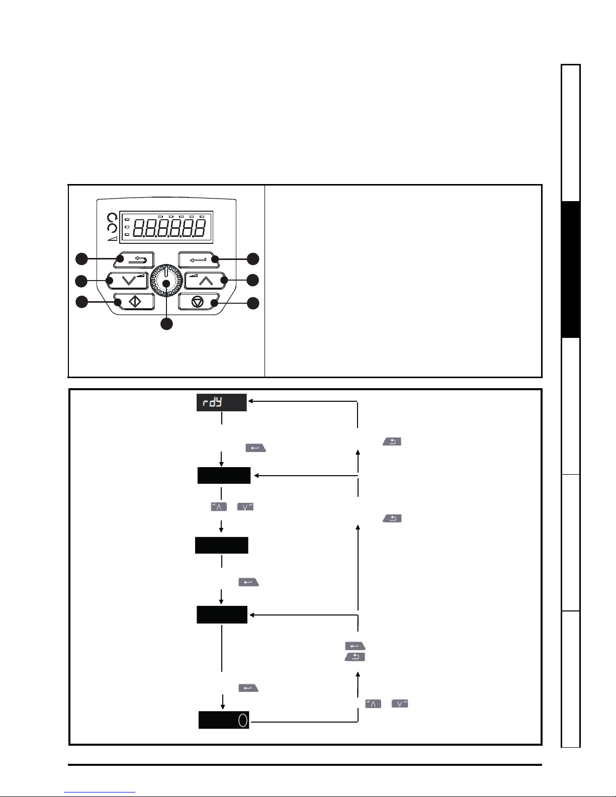
STEP 10: Use the keypad
The display provides information to the user regarding the operating status of the drive, alarms and trip code.
The keypad provides the means for changing parameters, stopping and starting the drive, and the ability to perform
a drive reset.
1
V A Hz rpm %
4
1
2
3
5
6
7
(1) The Enter button is used to enter parameter view or edit mode,
or to accept a parameter edit.
(2 / 6) The Navigation buttons can be used to select individual
parameters or to edit parameter values.
(3) The Stop / Reset button (red) is used to stop and reset the
drive in keypad mode (enabled for Unidrive M101 and M201). It
can also be used to reset the drive in terminal mode.
(4) The Speed Ref Potentiometer is used to control the frequency
reference (only on Unidrive M101 and M201).
(5) The Start button (green) is used to start the drive in keypad
mode (enabled for Unidrive M101 and M201).
(7) The Escape button is used to exit from the parameter edit /
view mode.
To return to Status Mode,
press button
To return to Parameter View Mode,
press button
Press or to select parameter
Status
Mode
To enter Parameter View Mode,
press button
Parameter
View Mode
Pr 10
Pr 01
0.00
0.00
To view parameter value
press button
To enter Edit Mode,
press button
0.00
Edit Mode (edited digit flashes)
Holding or increases or decreases value
Parameter
Value View
To return to Parameter Value View
press button to keep the new value
press
button to ignore new value and
return the parameter to the pre-edited value
Page 8
8 Unidrive M100/M101/M200/M201/M300 Step By Step Guide
Issue Number: 1
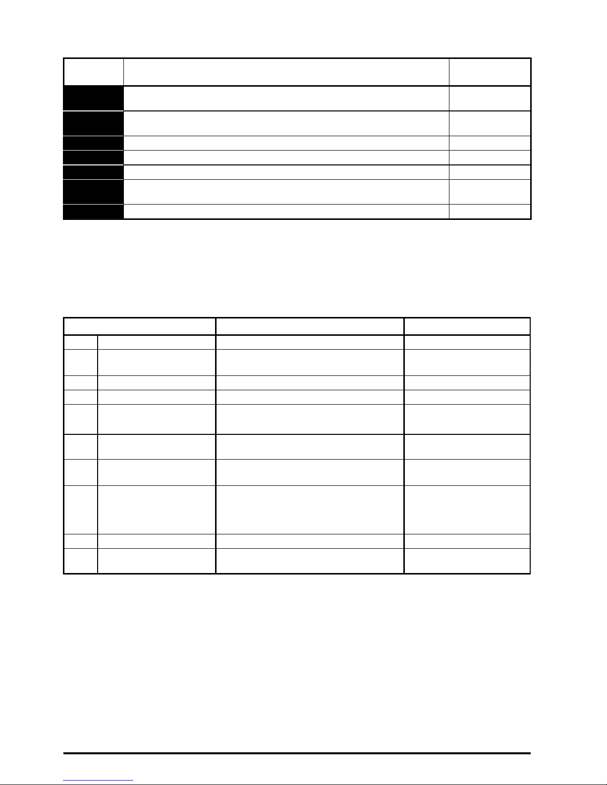
Table 10-1 Status indications
STEP 11: Understand key parameters and restoring default
When changing a parameter, the new value is saved when pressing the Enter button to return to parameter view
mode from parameter edit mode.
Restoring default parameters:
1. Ensure the drive is not enabled, i.e. terminal 11 (or terminal 31 and 34 on Unidrive M300) is open.
2. Select 'Def.50 (50 Hz settings) or Def.60 (60 Hz settings)’ in Pr 00.
3. Press the red reset button
String Description
Drive output
stage
inh
The drive is inhibited and cannot be run. The Drive Enable signal is not applied
to the drive enable terminal or is set to 0.
Disabled
rdy
The drive is ready to run. The drive enable is active, but the drive inverter is
not active because the final drive run is not active
Disabled
StoP The drive is stopped / holding zero speed. Enabled
S.Loss Supply loss condition has been detected Enabled
dc inj The drive is applying dc injection braking Enabled
Er
The drive has tripped and no longer controlling the motor. The trip code
appears on the display.
Disabled
UV The drive is in the under voltage state. Disabled
Parameter Range (Ú) Default (Ö)
01 Minimum Speed 0.00 to Pr 02 Hz 0.00 Hz
02 Maximum Speed 0.00 to 550.00 Hz
Def.50: 50.00 Hz
Def.60: 60.00 Hz
03 Acceleration Rate 1 0.0 to 32000.0 s/100 Hz 5.0 s/100 Hz
04 Deceleration Rate 1 0.0 to 32000.0 s/100 Hz 10.0 s/100 Hz
05 Drive Configuration
Refer to the Quick Start Guide for further
information on all drive configurations
M100/M200/M300: AV
M101/M201: PAd
06 Motor Rated Current 0.00 to Drive Rating Amps
Maximum Heavy Duty
Rating Amps
07 Motor Rated Speed 0.0 to 33000.0 rpm
Def.50: 1500.0 rpm
Def.60: 1800.0 rpm
08 Motor Rated Voltage 0 to 240 V or 0 to 480 V
110V drive: 230 V
200V drive: 230 V
400V drive Def.50: 400 V
400V drive Def.60: 460 V
09 Motor Rated Power Factor 0.00 to 1.00 0.85
10 User Security Status
Refer to the Quick Start Guide for further
information
LEVEL.1
Page 9
Unidrive M100/M101/M200/M201/M300 Step By Step Guide 9
Issue Number: 1
English
French German Italian Spanish
STEP 12: Run the motor
Troubleshooting
When the drive detects a fault it will display an error code. To locate and solve all error codes, a ‘Diagnostic Tool
(App)’ is available on Microsoft, Android and iOS platform via the ‘Apps’ store on Smartphone / Tablet, search for
‘Control Techniques diagnostics tool in the Apps store’.
Alternatively, please download the ‘Diagnostic Tool (App)’ from the Control Techniques ‘App Center’ or view the
diagnostics section in the Quick Start Guide available for download from the Control Techniques or Leroy Somer
website.
Action Detail
Power Up Ensure:
• The drive displays: inh (Enable terminal(s) is open)
Minimum and
maximum speed
Enter:
• Minimum speed Pr 01 (Hz)
• Maximum speed Pr 02 (Hz)
Accel and Decel
rates
Enter:
• Acceleration rate Pr 03 (s/100 Hz)
• Deceleration rate Pr 04 (s/100 Hz)
Motor nameplate
details
Ready to autotune
Autotune The drive is able to perform either a stationary or a rotating autotune. The motor must be at
a standstill before any autotune is enabled and disconnected from the load for a rotating
autotune.
To perform an autotune:
•Set Pr38 = 1 for a stationary autotune or set Pr 38 = 2 for a rotating autotune
• Close the drive enable signal (apply +24 V to terminal 11 or terminal 31 and 34 on
Unidrive M300). The drive will display ‘rdy’.
• Give a Run command (apply +24 V to terminal 12 - Run forward or terminal 13 Run reverse on Unidrive M100, M200 and M300; press keypad Start button on M101
and M201). The display will flash ‘tuning’ while the drive is performing the autotune.
• Wait for the drive to display ‘inh’ and for the motor to come to a standstill.
• Remove the drive enable and run signal from the drive.
Ready to run
Run The drive is now ready to run the motor. Close the Run Forward or Run Reverse terminals
on Unidrive M100, M200 and M300 only.
Increasing and
decreasing speed
Changing the selected Analog frequency reference (Speed Ref Potentiometer on M101 /
M201) will increase and decrease the speed of the motor.
Stopping To stop the motor by following the selected deceleration rate, open either the run forward or
run reverse terminal on Unidrive M100, M200 and M300 only. If the enable terminal is
opened while the motor is running, the drive output is immediately disabled and the motor
will coast to a stop.
n
Motor rated current in Pr 06 (Amps)
o
Motor rated speed in Pr 07 (rpm / min-1)
p
Motor rated voltage in Pr 08 (Volts)
q
Motor rated power factor in (cos φ) Pr 09
MOT. 3 LS 80 L T
N
734570 BJ 002 Kg 9
40 C S1IP 55 I cl.F
V Hz min kW cos
-1
A
230 50 2800 0,75 0,83 0,3
1
2
3
4
Page 10
10 Guide pas à pas pour l’Unidrive M100/M101/M200/M201/M300
Édition : 1
Français
ÉTAPE 1 : Vérification du contenu du carton
Vérifier que tous les éléments sont présents et que le variateur n’a pas été endommagé pendant le transport.
ÉTAPE 2 : Vérification du modèle et de la tension
Le numéro du modèle est indiqué sur l’étiquette d’identification qui se trouve sur le haut du variateur. Vérifier
que le modèle et la tension du variateur conviennent pour l’installation.
x4
+
+
+
SACHET DU KIT
ÉTRIER DE MISE À LA
TERRE DES CÂBLES
INFORMATIONS RELATIVES
À LA SÉCURITÉ
GUIDE PAS À PAS
1
M200 - 03 4 00073 A
1
Modèle Spécifications électriques
Gamme de
produits :
Taille :
Tension nominale :
1 - 100 V (100 - 120 ±10 %)
2 - 200 V (200 - 240 ±10 %)
4 - 400 V (380 - 480 ±10 %)
Format variateur :
A - Entrée AC et
sortie AC
Courant nominal :
Courant nominal x 10
Page 11
Guide pas à pas pour l’Unidrive M100/M101/M200/M201/M300 11
Édition : 1
English Français Deutsch Italiano Español
ÉTAPE 3 : Montage du variateur
Plage de température ambiante en fonctionnement :
- 20 à 60 °C
Un déclassement du courant de sortie peut être nécessaire pour des températures ambiantes >40 °C.
Consulter le Guide d’installation - Puissance (section 5.1). Pour les installations UL, la température ambiante
maximale autorisée est de 50 °C, quel que soit le déclassement appliqué.
Les variateurs peuvent être montés sans espacement entre eux. Prévoir un espacement minimum de 100 mm
au-dessus et au-dessous du variateur. Pour des informations concernant le déclassement applicable pour des
espacements inférieurs, se reporter à la section 3.4 du Guide d'installation - Puissance.
* Le Potentiomètre de référence de vitesse ajoute 11 mm supplémentaires à la profondeur totale pour les
variateurs Unidrive M101 et M201 uniquement.
Un gabarit de perçage pour le montage mural est fourni avec le variateur (voir l’illustration ci-dessous).
ÉTAPE 4 : Montage de l’étrier de mise à la terre
L’étrier de mise à la terre facilite la gestion des câbles après leur connexion au variateur. L’étrier est aussi utilisé
pour fixer le blindage des câbles à la terre afin de permettre la conformité CEM (voir la Figure 7-1).
Taille
Poids
HLP*Ø
Fixation Hors tout Fixation Hors tout Hors tout Diamètre
1 143 mm 160 mm 53 mm 75 mm 130 mm 5 mm 0,75 kg
2 194 mm 205 mm 55 mm 75 mm 150 mm 5 mm 1,3 kg
3 215 mm 226 mm 70,7 mm 90 mm 160 mm 5 mm 1,5 kg
4 265 mm 277 mm 86 mm 115mm 175mm 6mm 3,13kg
100 mm
100 mm
0 mm
Le variateur peut être fixé sur une plaque de fond ou monté sur un rail DIN (tailles 1 et 2
uniquement). En cas de montage du variateur sur un rail, utiliser 2 vis pour le fixer à la
plaque de fond.
+
+
+
+
4
V
I
S
M
4
Page 12
12 Guide pas à pas pour l’Unidrive M100/M101/M200/M201/M300
Édition : 1
ÉTAPE 5 : Sélection des câbles, fusibles ou disjoncteurs MCB
* Ces fusibles sont à action rapide.
** Pour les installations UL, le disjoncteur doit être listé sous le numéro de contrôle de la catégorie DIVQ / DIVQ7,
dimensionné pour 600 Vac avec une valeur nominale de court-circuit > 10 kA. Dans les autres pays, des
disjoncteurs conformes EN CEI 60947-2 sont recommandés, avec une capacité de court-circuit > 10 kA.
La tension nominale des fusibles et des disjoncteurs MCB doit être supérieure ou égale à la tension
d’alimentation la plus importante du système. Fusibles : l'alimentation AC appliquée au variateur doit
être équipée d'une protection adaptée contre les surcharges. Le non-respect de cette consigne peut
entraîner un risque d'incendie.
Taille du conducteur de terre : conducteur de 10 mm
2
ou deux conducteurs de la même section que
les conducteurs de phase en entrée.
Modèle
Phases
d'entrée
Fusibles
Disjoncteur
MCB**
Câbles
CEI classe
gG
UL classe
CC, J ou
T
*
CEI 60364-5-52
mm
2
UL 508C
AWG
A A Entrée Sortie Entrée Sortie
01100017 1 10 15 15 1 1 16 16
01100024 1 16 15 15 1,5 1 14 16
02100042 1 20 20 15 2,5 1 12 16
02100056 1 25 25 15 4 1 10 16
01200017 1 6 6 15 1 1 16 16
01200024 1 6 6 15 1 1 16 16
01200033 1 10 15 15 1 1 16 16
01200042 1 16 15 15 1 1 16 16
02200024 1 / 3 6/6 6/6 15 1 1 16 16
02200033 1 / 3 10/10 10/10 15 1 1 16 16
02200042 1 / 3 16/10 15/10 15 1 1 16 16
02200056 1 / 3 20/16 20/15 15 2,5/1,5 1 12/14 16
02200075 1 / 3 20/16 20/15 15 2,5 1 12 16
03200100 1 / 3 25/20 25/20 25/20 4 1,5 10/12 14
04200133 1 / 3 25/20 25/20 25/20 4/2,5 2,5 10 12
04200176 3 25 25 25 4 2,5 10 12
02400013 3 6 6 15 1 1 16 16
02400018 3 6 6 15 1 1 16 16
02400023 3 6 6 15 1 1 16 16
02400032 3 6 6 15 1 1 16 16
02400041 3 10 6 15 1 1 16 16
03400056 3 10 15 15 1 1 14 16
03400073 3 16 15 15 1,5 1 12 16
03400094 3 16 15 25 2,5 1,5 12 14
04400135 3 20 20 20 2,5 2,5 10 12
04400170 3 25 25 25 4 2,5 10 12
Le produit est conforme UL et peut être utilisé dans un circuit dont le défaut en courant symétrique
maximum de l'alimentation est de 100 kA en présence de fusibles de protection.
Les sections de câble conformes CEI sont basées sur un conducteur en cuivre, une isolation PVC,
une méthode d’installation des câbles B2 et une température ambiante de 40 °C. Les sections de câble
conformes UL sont basées sur un conducteur en cuivre, avec une isolation prévue pour 75 °C.
AVERTISSEMENT
NOTE
NOTE
NOTE
Page 13
Guide pas à pas pour l’Unidrive M100/M101/M200/M201/M300 13
Édition : 1
English Français Deutsch Italiano Español
ÉTAPE 6 : Démontage du capot
1. À l’aide d’un tournevis plat, faire tourner le clip de fixation du capot d’environ 30° dans le sens anti-horaire.
2. Faire glisser le capot vers le bas.
3. Retirer le capot dans le sens indiqué.
ÉTAPE 7 : Identification des caractéristiques du variateur
Figure 7-1 Schéma de localisation (taille 2 illustrée)
Tableau 7-1 Couples de serrage recommandés
Tailles Description du bornier Couple de serrage
Toutes
Bornes de contrôle 0,2 N m
Bornes de relais 0,5 N m
1
Bornes de puissance
0,5 N m
2, 3, 4 1,4 N m
Toutes Bornes de terre 1,5 N m
2
3
1
+
EMC
MOV
L1 L2 L3
U V W - + BR
2
1
3
12
10
7
5
11
11
9
8
6
4
13
Légende
1. Étiquette de valeurs nominales (sur le côté du variateur)
2. Étiquette d'identification
3. Connexions relais
4. Raccordements de contrôle
5. Borne de freinage
6. Vis du filtre CEM interne*
7. Bus DC +
8. Bus DC -
9. Raccordements au moteur
10. Raccordement de l'alimentation AC
11. Raccordements à la terre
12. Bornes d'Absence sûre du couple (STO)**
13. Étrier de mise à la terre à visser sur les bornes de
terre (11)
* Avant de retirer la vis, consulter la section 4.7.2 du
Guide d’installation - Puissance.
** Unidrive M300 uniquement.
Page 14
14 Guide pas à pas pour l’Unidrive M100/M101/M200/M201/M300
Édition : 1
ÉTAPE 8 : Câblage du variateur
M100/M200/M300 : Le schéma de câblage correspond à la configuration par défaut du variateur (Pr 05 réglé sur AV)
qui est un contrôle de fréquence via l’entrée analogique 1 (0 à 10 V) ou l’entrée analogique 2 (0 à 10 V),
sélectionnable à l’aide de la borne 14.
M101/M201 : La configuration par défaut utilise le Potentiomètre de référence de vitesse embarqué à la place de
l’entrée analogique pour la référence de fréquence (seule la borne de déverrouillage du variateur est nécessaire).
Figure 8-1 Raccordements des bornes de puissance
* En monophasé, l’alimentation doit être raccordée à L1 et L3.
Figure 8-2 Raccordements des bornes de contrôle de l’Unidrive M100/M101
Figure 8-3 Raccordements des bornes de contrôle de l’Unidrive M200/M201/M300
** Non nécessaire sur les variateurs Unidrive M101 et M201 étant donné qu’ils sont déjà équipés du Potentiomètre
de référence de vitesse. Les commande Marche/Arrêt sont données à partir du clavier et si la marche arrière est
nécessaire, l'utilisateur doit régler Pr 17 sur On.
*** L’Unidrive M300 utilise les entrées Absence sûre du couple (déverrouillage du variateur) et la borne 11 n’est pas
affectée.
**** 250 Vac maximum (UL classe 1).
Consulter la section 4.4 du Guide de mise en service rapide pour des informations complémentaires et les
schémas de câblage des autres configurations proposées.
Une résistance de freinage externe peut être utilisée, si nécessaire. Consulter la section 4.5.1 du Guide d'installation -
Puissance pour de plus amples informations.
L1
L2
L3
U
V
W
Alimentation AC
Moteur
Alimentation AC
monophasée*/
triphasée
9
10
11
12
13
1
2
4
41
42
E/S logiques
Relais****
E/S analogique
Fréquence Nulle
Déverrouillage
du variateur
Marche avant**
Marche arrière**
Variateur prêt
24 V utilisateur
E/S logique 1
Entrée logique 2
Entrée logique 3
Entrée logique 4
Référence
fréquence**
10 kΩ
0 V
Entrée analogique 1
10 V utilisateur
9
10
11
12
13
14
41
42
1
2
7
4
5
10 kΩ
10 kΩ
34
33
31
32
0 V
E/S logiques
Relais 1****
E/S analogiques
Fréquence Nulle
Déverrouillage
du variateur***
Marche avant**
Marche arrière**
Sélection entrée
analogique 1 / entrée
analogique 2
Référence
fréquence 1**
Référence
fréquence 2**
Sortie fréquence
M300 uniquement
24 V utilisateur
E/S logique 1
Entrée logique 2
Entrée logique 3
Entrée logique 4
Entrée logique 5
0 V
Entrée analogique 1
10 V utilisateur
Entrée analogique 2
Sortie analogique 1
24 V utilisateur
Variateur prêt
Absence sûre du couple
(Safe Torque
Off)
ST01
0 V
ST01
0 V
ST02
ST02
Page 15
Guide pas à pas pour l’Unidrive M100/M101/M200/M201/M300 15
Édition : 1
English Français Deutsch Italiano Español
ÉTAPE 9 : Mise sous tension du variateur
• S’assurer que le signal de déverrouillage du variateur n’est pas activé, la borne 11 (ou les bornes 31 et 34 de
l’Unidrive M300) est ouverte.
• S’assurer que le signal de marche n’est pas activé, les bornes 12 et 13 sont ouvertes (Unidrive M100, M200 et
M300).
• S’assurer que le moteur est raccordé au variateur.
• S’assurer que le raccordement du moteur (Δ ou Y) est correct.
ÉTAPE 10 : Utilisation du clavier
L’afficheur présente des informations relatives à l’état de fonctionnement du variateur, aux codes et alarmes de
sécurité. Le clavier peut être utilisé pour modifier les paramètres, arrêter et mettre en marche le variateur ou faire
un reset du variateur.
1
V A Hz rpm %
4
1
2
3
5
6
7
(1) La touche Entrée est utilisée pour passer en mode Modification
ou visualisation, ou pour valider un changement de paramètre.
(2 / 6) Les touches de navigation permettent de sélectionner les
paramètres ou de modifier leurs valeurs.
(3) En mode clavier, la touche Arrêt / Reset (rouge) permet d’arrêter
et de faire un reset du variateur (activée pour l'Unidrive M101 et
M201). En mode bornier, cette touche permet seulement de faire un
reset du variateur.
(4) Le Potentiomètre de référence de vitesse est utilisé pour
contrôler la référence de fréquence (uniquement sur les variateurs
Unidrive M101 et M201).
(5) En mode clavier, la touche Marche (verte) est utilisée pour
mettre en marche le variateur (activée pour l'Unidrive M101 et
M201).
(7) La touche Échap permet de quitter le mode Modification /
Visualisation.
Pr 10
Pr 01
0.00
0.00
Mode
État
Pour passer en mode
Visualisation des paramètres,
appuyer sur la touche
Mode
Visualisation
des paramètres
Affichage
de la valeur
du paramètre
Appuyer sur ou
pour sélectionner un paramètre
Pour afficher la valeur du paramètre,
appuyer sur la touche
Pour passer en mode Modification,
appuyer sur la touche
Pour repasser en mode État,
appuyer sur la touche
Pour repasser en mode
Visualisation des paramètres,
appuyer sur la touche
Mode Modification (le digit à modifier clignote)
Maintenir enfoncée la touche ou pour augmenter
ou diminuer la valeur
Pour revenir à l’affichage de la valeur du paramètre
Appuyer sur la touche pour conserver la nouvelle valeur
Appuyer sur la touche pour ignorer la nouvelle valeur du
paramètre et rétablir la valeur préalable à la modification
Page 16

16 Guide pas à pas pour l’Unidrive M100/M101/M200/M201/M300
Édition : 1
Tableau 10-1 Indications d'état
ÉTAPE 11 : Explication des paramètres principaux et restauration
des valeurs par défaut
Lors de la modification d'un paramètre, la nouvelle valeur est sauvegardée en appuyant sur la touche Entrée pour
passer du Mode Modification au Mode Visualisation.
Restauration de la valeur par défaut des paramètres :
1. S’assurer que le variateur est verrouillé, la borne 11 (ou les bornes 31 et 34 de l’Unidrive M300) est ouverte.
2. Sélectionner ‘Def.50’ (paramètres 50 Hz) ou ‘Def.60’ (paramètres 60 Hz) dans Pr 00.
3. Appuyer sur la touche Reset rouge.
Mnémonique Description
Sortie du
variateur
inh
Le variateur est verrouillé et ne peut pas être mis en marche. Le signal de
déverrouillage variateur n'est pas appliqué à la borne de déverrouillage ou est
réglé sur 0.
Désactivée
rdy
Le variateur est prêt pour la mise en marche. Le déverrouillage du variateur est
actif mais l'onduleur du variateur n'est pas actif parce que le signal de marche
final n'est pas actif.
Désactivée
StoP Le variateur est arrêté/maintient le moteur à vitesse nulle. Activée
S.Loss Une condition de perte d'alimentation a été détectée. Activée
dc inj Le variateur applique un freinage par injection de courant DC. Activée
Er
Le variateur a déclenché une sécurité et ne contrôle plus le moteur. Le code de
mise en sécurité apparaît sur l'afficheur.
Désactivée
UV Le variateur est en état de sous-tension. Désactivée
Paramètre Plage (Ú) Valeur par défaut (Ö)
01 Vitesse minimum 0,00 à Pr 02 Hz 0,00 Hz
02 Vitesse maximum 0,00 à 550,00 Hz
Def.50 : 50,00 Hz
Def.60 : 60,00 Hz
03 Rampe d'accélération 1 0,0 à 32000,0 s/100 Hz 5,0 s/100 Hz
04 Rampe de décélération 1 0,0 à 32000,0 s/100 Hz 10,0 s/100 Hz
05 Configuration du variateur
Consulter le Guide de mise
en service rapide pour de plus amples
informations sur toutes les configurations
du variateur.
M100/M200/M300: AV
M101/M201: PAd
06 Courant nominal moteur 0,00 à la puissance nominale du variateur
Courant nominal en surcharge
maximum A
07 Vitesse nominale moteur
0,0 à 33000,0 min
-1
Def.50 : 1500,0 min
-1
Def.60 : 1800,0 min
-1
08 Tension nominale moteur 0 à 240 V ou 0 à 480 V
Variateur 110 V : 230 V
Variateur 200 V : 230 V
Variateur 400 V Def. 50 : 400 V
Variateur 400 V Def. 60 : 460 V
09
Facteur de puissance
nominal moteur
0,00 à 1,00 0,85
10 État de sécurité utilisateur
Consulter le Guide de mise
en service rapide pour de plus amples
informations.
LEVEL.1
Page 17

Guide pas à pas pour l’Unidrive M100/M101/M200/M201/M300 17
Édition : 1
English Français Deutsch Italiano Español
ÉTAPE 12 : Mise en marche du moteur
Dépannage
Lorsque le variateur détecte un défaut, il affiche un code d’erreur. Pour localiser et corriger tous les codes d’erreur,
l’application « Diagnostic Tool (App) » est disponible sur les plateformes Microsoft, Android et iOS via l’App Store.
Sur smartphone / tablette, rechercher « Control Techniques diagnostics tool dans l’App Store ».
Cette application peut également être téléchargée à partir de l’App Center de Control Techniques. Consulter aussi
le chapitre sur les diagnostics dans le Guide de mise en service rapide accessible en téléchargement sur le site
Web de Control Techniques ou de Leroy Somer.
Action Description
Mise sous tension Vérifier que :
• Le variateur affiche : inh (borne(s) Déverrouillage ouverte(s))
Vitesses minimum et
maximum
Entrer :
• la vitesse minimum dans Pr 01 (Hz)
• la vitesse maximale dans Pr 02 (Hz)
Rampes d'accél./
décél.
Entrer :
• la rampe d'accélération dans Pr 03 (s/100 Hz)
• la rampe de décélération dans Pr 04 (s/100 Hz)
Données figurant sur
la plaque signalétique
moteur
Variateur prêt pour l’autocalibrage
Autocalibrage Le variateur est en mesure de faire un autocalibrage à l'arrêt ou en rotation. Le moteur doit être
immobile avant l'activation d'un autocalibrage et déconnecté de la charge pour un autocalibrage
avec rotation.
Pour effectuer un autocalibrage :
• Régler le paramètre Pr 38 sur 1 pour procéder à un autocalibrage à l'arrêt ou Pr 38 sur 2 pour
un autocalibrage avec rotation.
• Activer le signal de déverrouillage (appliquer +24 V à la borne 11 ou aux bornes 31 et 34 de
l’Unidrive M300). Le variateur affiche « rdy ».
• Donner une commande Marche (appliquer +24 V à la borne 12 – Marche avant ou à la
borne 13 – Marche arrière sur l'Unidrive M100, M200 et M300 ; appuyer sur la touche Marche
du clavier sur l'Unidrive M101 et M201). Tout au long de l'exécution de l'autocalibrage,
l'afficheur du variateur indiquera « tuning ».
• Attendre que le variateur affiche « Inh » et que le moteur soit à l'arrêt.
• Supprimer le signal de déverrouillage et l'ordre de marche du variateur.
Variateur prêt pour la mise en marche
Mise en marche Le variateur est prêt à entraîner le moteur. Donner un ordre de marche avant ou de marche arrière
sur l'Unidrive M100, M200 et M300 uniquement.
Augmentation et
réduction de la
vitesse
Tout changement de la référence de fréquence analogique sélectionnée (Potentiomètre de
référence de vitesse sur l’Unidrive M101 / M201) augmente ou diminue la vitesse du moteur.
Arrêt Pour un arrêt du moteur avec la rampe de décélération sélectionnée, ouvrir la borne de marche
avant ou de marche arrière sur l'Unidrive M100, M200 et M300 uniquement. Si la borne de
déverrouillage est ouverte lorsque le moteur est en rotation, la sortie du moteur est immédiatement
désactivée et le moteur s'arrête en roue libre.
n
Le courant nominal du moteur dans Pr 06 (A)
o
La vitesse nominale du moteur dans Pr 07 (min-1)
p
La tension nominale du moteur dans Pr 08 (V)
q
Le facteur de puissance nominale (cos φ) dans Pr 09
MOT. 3 LS 80 L T
N
734570 BJ 002 Kg 9
40 C S1IP 55 I cl.F
V Hz min kW cos
-1
A
230 50 2800 0,75 0,83 0,3
1
2
3
4
Page 18

18 Schritt-für-Schritt-Anleitung Unidrive M100/M101/M200/M201/M300
Ausgabenummer: 1
Deutsch
SCHRITT 1: Verpackungsinhalt prüfen
Kontrollieren Sie, dass alle Komponenten vorhanden sind und dass der Umrichter während des Transports nicht
beschädigt wurde.
SCHRITT 2: Gerätetyp und Spannung prüfen
Den Gerätetyp finden Sie auf dem Identifikationsschild oben am Umrichter. Überprüfen Sie, dass Gerätetyp
und Spannungsbereich des Umrichters für die Anwendung geeignet sind.
x4
+
+
+
ZUBEHÖRBEUTEL
KABELHALTERUNG
SICHERHEITS-
INFORMATIONEN
SCHRITT-FÜR-SCHRITTANLEITUNG
1
M200 - 03 4 00073 A
1
Gerätetyp Elektrische Daten
Produktlinie:
Baugröße:
Nennspannung:
1 - 100 V (100 - 120 ±10 %)
2 - 200 V (200 - 240 ±10 %)
4 - 400 V (380 - 480 ±10 %)
Umrichterformat:
A–AC Eingang AC
Ausgang
Bemessungsstrom:
Nennstrom bei hoher Überlast
(Heavy Duty) x10
Page 19
Schritt-für-Schritt-Anleitung Unidrive M100/M101/M200/M201/M300 19
Ausgabenummer: 1
English Français Deutsch Italiano Español
SCHRITT 3: Umrichter montieren
Betriebsbereich der Umgebungstemperatur:
- 20 °C bis 60 °C
Bei Umgebungstemperaturen > 40 °C kann eine Reduzierung der Ausgangsleistung erforderlich sein.
Siehe Leistungsmodul-Installationshandbuch (Abschnitt 5.1). Bei UL-Installationen ist die maximal zulässige
Umgebungstemperatur 50 °C bei vorgegebener Leistungsreduzierung.
Umrichter können in Schaltschränken mit 0 mm Abstand zwischen den Umrichtern montiert werden. Über und
unter dem Umrichter ist ein Mindestabstand von 100 mm erforderlich. Informationen zur Leistungsreduzierung
bei verringerten Abständen finden Sie in Abschnitt 3.4 des Leistungsmodul-Installationshandbuchs.
* Beim Unidrive M101 und M201 ist die Gesamttiefe durch das Drehzahlsollwert-Potentiometer um 11 mm größer.
Eine Bohrschablone für die Wandmontage ist in der Umrichterverpackung enthalten (nachstehend abgebildet).
SCHRITT 4: Kabelhalterung montieren
Die Kabelhalterung erleichtert die Führung der Kabel, nachdem sie an den Umrichter angeschlossen wurden.
Mit der Halterung wird die Abschirmungen der Kabel geklemmt, welche die EMV-Konformität erleichtert
(siehe Abbildung 7-1).
Baugröße
Gewicht
HW
D
*
Ø
Aufstellung Gesamt Aufstellung Gesamt Gesamt Durchmesser
1 143 mm 160 mm 53 mm 75 mm 130 mm 5 mm 0,75 kg
2 194 mm 205 mm 55 mm 75 mm 150 mm 5 mm 1,3 kg
3 215 mm 226 mm 70,7 mm 90 mm 160 mm 5 mm 1,5 kg
4 265 mm 277 mm 86 mm 115mm 175mm 6mm 3,13kg
100 mm
100 mm
0 mm
Der Umrichter kann direkt an der Wand verschraubt oder an einer DIN-Hutschiene
montiert werden (nur Baugröße 1 und 2). Wenn er an einer Schiene montiert werden soll,
sichern Sie den Umrichter mit 2 Schrauben an der Rückwand.
+
+
+
+
4
xM
4
S
C
H
R
AU
B
E
N
Page 20

20 Schritt-für-Schritt-Anleitung Unidrive M100/M101/M200/M201/M300
Ausgabenummer: 1
SCHRITT 5: Kabel und Sicherungen oder Sicherungsautomaten
auswählen
* Diese Sicherungen sind flink.
** Bei UL-Installationen muss der Leistungsschalter unter der Kategoriekontrollnummer DIVQ / DIVQ7 gelistet sein,
Nennspannung 600 VAC mit Kurzschlussfestigkeit > 10 kA. In anderen Ländern werden Leistungsschalter gemäß
EN IEC 60947-2 mit einem Kurzschlussausschaltvermögen > 10 kA empfohlen.
Die Nennspannung der Sicherungen und Sicherungsautomaten muss mindestens so hoch sein wie die
maximale Versorgungsspannung des Systems. Sicherungen: Der Netzanschluss des Umrichters
muss mit einem geeigneten Überlastschutz installiert werden. Bei Nichtbeachtung dieser Vorgabe
besteht die Gefahr eines Brandes.
Leitungsquerschnitt der Erdverbindung: Entweder 10 mm
2
oder zwei Kabel mit dem gleichen
Leitungsquerschnitt des Netzanschlusses.
Gerätetyp
Eingangs-
phasen
Sicherungen
Bemessungs-
daten
Sicherungs-
automat**
Kabel
IEC-
Klasse gG
UL-Klasse
CC J
oder T*
IEC60364-5-52
mm
2
UL 508C
AWG
A A Eingang Ausgang Eingang Ausgang
01100017 1 10 15 15 1 1 16 16
01100024 1 16 15 15 1,5 1 14 16
02100042 1 20 20 15 2,5 1 12 16
02100056 1 25 25 15 4 1 10 16
01200017 1 6 6 15 1 1 16 16
01200024 1 6 6 15 1 1 16 16
01200033 1 10 15 15 1 1 16 16
01200042 1 16 15 15 1 1 16 16
02200024 1 / 3 6/6 6/6 15 1 1 16 16
02200033 1 / 3 10/10 10/10 15 1 1 16 16
02200042 1 / 3 16/10 15/10 15 1 1 16 16
02200056 1 / 3 20/16 20/15 15 2,5/1,5 1 12/14 16
02200075 1 / 3 20/16 20/15 15 2,5 1 12 16
03200100 1 / 3 25/20 25/20 25/20 4 1,5 10/12 14
04200133 1 / 3 25/20 25/20 25/20 4/2,5 2,5 10 12
04200176 3 25 25 25 4 2,5 10 12
02400013 3 6 6 15 1 1 16 16
02400018 3 6 6 15 1 1 16 16
02400023 3 6 6 15 1 1 16 16
02400032 3 6 6 15 1 1 16 16
02400041 3 10 6 15 1 1 16 16
03400056 3 10 15 15 1 1 14 16
03400073 3 16 15 15 1,5 1 12 16
03400094 3 16 15 25 2,5 1,5 12 14
04400135 3 20 20 20 2,5 2,5 10 12
04400170 3 25 25 25 4 2,5 10 12
Das Produkt besitzt eine UL-Zulassung für den Einsatz in einem Stromkreis bis max. 100 kA
Netzkurzschlussstrom bei Verwendung entsprechender Sicherungen.
IEC-Kabelquerschnitte beziehen sich auf einen Kupferleiter, PVC-Isolierung, Installationsmethode B2
und eine Umgebungstemperatur von 40 °C. UL-Kabelquerschnitte beziehen sich auf einen Kupferleiter
mit Isolierung bei 75 °C.
WARNUNG
HINWEIS
HINWEIS
HINWEIS
Page 21

Schritt-für-Schritt-Anleitung Unidrive M100/M101/M200/M201/M300 21
Ausgabenummer: 1
English Français Deutsch Italiano Español
SCHRITT 6: Abdeckung abnehmen
1. Drehen Sie die Verriegelung der Klemmenabdeckung mit einem Schlitzschraubendreher um etwa 30° gegen
den Uhrzeigersinn.
2. Schieben Sie die Klemmenabdeckung nach unten.
3. Entfernen Sie die Klemmenabdeckung in der dargestellten Richtung.
SCHRITT 7: Identifikation der Umrichteranschlüsse
Abbildung 7-1 Anschlussdiagramm (Abbildung zeigt Baugröße 2)
Tabelle 7-1 Empfohlene Anzugsdrehmomente
Gerätebaugröße Klemmenblock Beschreibung Anzugsdrehmomente
Alle
Steueranschlussklemmen 0,2 Nm
Relaisklemmen 0,5 Nm
1
Klemmenanschlüsse - Leistung
0,5 Nm
2, 3, 4 1,4 Nm
Alle Erdungsanschlüsse 1,5 Nm
2
3
1
+
EMC
MOV
L1 L2 L3
U V W - + BR
2
1
3
12
10
7
5
11
11
9
8
6
4
13
Legende
1. Typenschild (an der Seite des Umrichters)
2. Identifikationsschild
3. Relaisanschlussklemmen
4. Steueranschlüsse
5. Anschlussklemmen für den Bremswiderstand
6. Schraube f. internes EMV-Filter*
7. DC Bus +
8. DC Bus -
9. Motoranschlüsse
10. Netzverbindung
11. Erdung
12. Safe Torque Off Klemmen (STO)**
13. Kabelhalterung, wird auf die Erdungsanschlüsse (11)
geschraubt
* Vor dem Entfernen der Schraube Abschnitt 4.7.2 des
Leistungsmodul-Installationshandbuchs lesen.
** Nur Unidrive M300.
Page 22
22 Schritt-für-Schritt-Anleitung Unidrive M100/M101/M200/M201/M300
Ausgabenummer: 1
SCHRITT 8: Umrichter verkabeln
M100/M200/M300: Der Schaltplan gilt für die Standard-Umrichterkonfiguration (Pr 05 auf AV), d. h. Frequenzsteuerung
über Analogeingang 1 (0-10 V) oder Analogeingang 2 (0-10 V), Anwahl über Klemme 14.
M101/M201: In der Standardeinstellung wird für den Referenzwert anstelle des Analogeingangs eher das integrierte
Drehzahlsollwert-Potentiometer verwendet (hierfür wird nur die Anschlussklemme zur Umrichterfreigabe benötigt).
Abbildung 8-1 Netzanschlussklemmen
* Bei einer einphasigen Netzversorgung wird die Versorgung an L1 und L3 angeschlossen.
Abbildung 8-2 Unidrive M100/M101 Steuerklemmenbelegung
Abbildung 8-3 Unidrive M200/M201/M300 Steuerklemmenbelegung
** Bei Unidrive M101 und M201 nicht erforderlich, da das Drehzahlsollwert-Potentiometer bereits in das Produkt
integriert ist. Die Start/Stopp-Befehle werden über die Bedieneinheit erteilt; wird Linkslauf benötigt, muss der
Bediener Pr 17 auf EIN schalten.
*** Unidrive M300 verwendet die Eingänge Safe Torque Off (Umrichterfreigabe), Klemme 11 ist nicht zugewiesen.
**** 250 VAC max. (UL-Klasse 1).
Informationen und Schaltpläne für alternative Konfigurationen finden Sie in Abschnitt 4.4 der Kurzanleitung.
Bei Bedarf kann ein externer Bremswiderstand angeschlossen werden. Weitere Informationen finden Sie im
Abschnitt 4.5.1 des Leistungsmodul-Installationshandbuchs.
L1
L2
L3
U
V
W
Netzanschluss
Motor
1-*/3-phasiger
Netzanschluss
9
10
11
12
13
1
2
4
41
42
Digitale E/A
Relais****
Analoge E/A
Nulldrehzahl
Umrichterfreigabe
Rechtslauf**
Linkslauf**
Betriebsbereit
24-V-Abnehmer
Digitaler Ein-/Ausgang 1
Digitaleingang 2
Digitaleingang 3
Digitaleingang 4
Frequenzsollwert**
10 kΩ
0 V
Analogeingang 1
10-V-Abnehmer
9
10
11
12
13
14
41
42
1
2
7
4
5
10 kΩ
10 kΩ
34
33
31
32
0 V
Digitale E/A
Relais 1****
Analoge E/A
Nulldrehzahl
Umrichterfreigabe***
Rechtslauf**
Linkslauf**
Auswahl Analog-
eingang 1 oder 2
Frequenzsollwert 1**
Frequenzsollwert 2**
Frequenzausgang
Nur M300
24-V-Abnehmer
Digitaler Ein-/ Ausgang 1
Digitaleingang 2
Digitaleingang 3
Digitaleingang 4
Digitaleingang 5
0 V
Analogeingang 1
10-V-Abnehmer
Analogeingang 2
Analogausgang 1
24-V-Abnehmer
Betriebsbereit
Safe Torque
Off
ST01
0V
ST01
0V
ST02
ST02
Page 23

Schritt-für-Schritt-Anleitung Unidrive M100/M101/M200/M201/M300 23
Ausgabenummer: 1
English Français Deutsch Italiano Español
SCHRITT 9: Einschalten des Umrichters
• Stellen Sie sicher, dass die Umrichterfreigabe nicht gesetzt ist, d. h. Klemme 11 (bzw. Klemmen 31 und 34
beim Unidrive M300) offen ist (sind).
• Stellen Sie sicher, dass das Drehrichtungssignal nicht gesetzt ist und Klemmen 12 und 13 offen sind
(Unidrive M100, M200 und M300).
• Stellen Sie sicher, dass der Motor an den Umrichter angeschlossen ist.
• Stellen Sie sicher, dass der Motor korrekt angeschlossen ist (Δ oder Y).
SCHRITT 10: Verwendung der Bedieneinheit
Das Display zeigt dem Benutzer Informationen zum Betriebszustand des Umrichters, Alarmen und
Abschaltungscodes an. Die Bedieneinheit bietet die Möglichkeit, Parameter zu ändern, den Umrichter zu starten
und zu stoppen sowie den Umrichter zurückzusetzen.
1
V A Hz rpm %
4
1
2
3
5
6
7
(1) Die Enter-Taste dient dem Aufruf des Anzeige- oder
Bearbeitungsmodus der Parameter oder der Bestätigung eines
bearbeiteten Parameters.
(2 / 6) Die Navigationstasten dienen zur Auswahl eines bestimmten
Parameters oder zur Bearbeitung von Parameterwerten.
(3) Die Stop/Reset-Taste (rot) dient zum Anhalten des Umrichters
im Keypad-Modus (aktiviert beim Unidrive M101 & M201).
Sie kann auch zum Rücksetzen des Umrichters im Modus für
Klemmenansteuerung verwendet werden.
(4) Die Drehzahlsollwert-Potentiometer-Taste dient zur Regelung
des Frequenzsollwerts (nur beim Unidrive M101 und M201).
(5) Die Start-Taste (grün) dient zum Starten des Umrichters im
Keypad-Modus (aktiviert beim Unidrive M101 und M201).
(7) Die Escape-Taste dient zum Verlassen des Modus
Parameterbearbeitung/-anzeige.
Pr 10
Pr 01
0.00
0.00
Statusmodus
Zum Wechseln in den Modus ‚Parameter anzeigen‘
drücken Sie
ParameterAnzeigemodus
Anzeige des
Parameterwerts
Um den Parameter auszuwählen,
drücken Sie oder
Zur Anzeige des Parameterwerts
drücken Sie die Taste
Zum Wechseln in den Bearbeitungsmodus
die Taste drücken
Zur Rückkehr zum Statusmodus
drücken Sie
Zur Rückkehr zum Parameter-Anzeigemodus
drücken Sie
Modus ,Parameter ändern’ (bearbeitete Ziffer blinkt)
Durch Halten von oder wird der Wert erhöht bzw. verringert.
Um zur Ansicht Parameterwerte zurückzukehren,
drücken Sie die Taste , um den neuen Parameterwert zu behalten
drücken Sie die Taste , um den neuen Parameterwert zu ignorieren
und den Parameterwert auf den Wert vor der Bearbeitung zurückzusetzen
Page 24

24 Schritt-für-Schritt-Anleitung Unidrive M100/M101/M200/M201/M300
Ausgabenummer: 1
Tabelle 10-1 Anzeige von Statusinformationen
SCHRITT 11: Hauptparameter und Wiederherstellen der
Standardparameter
Beim Ändern von Parametern wird der neue Wert beim Betätigen der Eingabetaste gespeichert. Dann kehrt der
Umrichter vom Modus „Parameter ändern“ in den Modus „Parameter anzeigen“ zurück.
Wiederherstellen der Standardparameter:
1. Stellen Sie sicher, dass die Umrichterfreigabe nicht gesetzt ist, d. h. Klemme 11 (bzw. Klemmen 31 und 34
beim Unidrive M300) offen ist (sind).
2. Wählen Sie Def.50 (50-Hz-Einstellungen) oder Def.60 (60-Hz-Einstellungen) in Pr 00.
3. Drücken Sie die rote RESET-Taste.
Textstring Beschreibung
Ausgangsstufe
des Umrichters
inh
Der Umrichter ist gesperrt und kann nicht betrieben werden. Das Signal Drive
Enable (Umrichterfreigabe) wird nicht auf die Klemme Drive Enable gelegt oder
ist auf 0 gesetzt.
Deaktiviert
rdy
Der Umrichter kann gestartet werden. Die Umrichterfreigabe ist aktiviert, aber
der Umrichter ist nicht aktiv, weil der endgültige Startbefehl nicht aktiviert ist.
Deaktiviert
StoP Der Umrichter ist gestoppt/wird auf Nulldrehzahl gehalten. Freigegeben
S.Loss Es wurde ein Verlust der Stromversorgung erfasst. Freigegeben
dc inj Die Gleichstrombremsung ist aktiv. Freigegeben
Er
Eine Fehlerabschaltung des Umrichters wurde ausgelöst, so dass der Motor
nicht mehr vom Umrichter gesteuert wird. Der Fehlercode wird auf dem Display
angezeigt.
Deaktiviert
UV Der Umrichter befindet sich im Status Unterspannung. Deaktiviert
Parameter Bereich (Ú) Standardwerte (Ö)
01 Min. Drehzahl 0,00 bis Pr 02 Hz 0,00 Hz
02 Max. Drehzahl 0,00 bis 550,00 Hz
Def.50: 50,00 Hz
Def.60: 60,00 Hz
03 Beschleunigungszeit 1 0,0 bis 32000,0 s/100 Hz 5,0 s/100 Hz
04 Verzögerungszeit 1 0,0 bis 32000,0 s/100 Hz 10,0 s/100 Hz
05 Umrichterkonfiguration
Weitere Informationen zu allen
Umrichterkonfigurationen können der
Kurzanleitung entnommen werden.
M100/M200/M300: AV
M101/M201: PAd
06 Motornennstrom 0,00 bis Umrichternennstrom
Maximaler Nennstrom bei
hoher Überlast (Heavy Duty A)
07 Motornenndrehzahl
0,0 bis 33000,0 min
-1
Def.50: 1500,0 min
-1
Def.60: 1800,0 min
-1
08 Motornennspannung 0 bis 240 V oder 0 bis 480 V
110-V-Umrichter: 230 V
200-V-Umrichter: 230 V
400-V-Umrichter Def.50: 400 V
400-V-Umrichter Def.60: 460 V
09 Motorleistungsfaktor 0,00 bis 1,00 0,85
10 Benutzersicherheitsstatus
Weitere Informationen können der
Kurzanleitung entnommen werden.
LEVEL.1
Page 25
Schritt-für-Schritt-Anleitung Unidrive M100/M101/M200/M201/M300 25
Ausgabenummer: 1
English Français Deutsch Italiano Español
SCHRITT 12: Motorbetrieb
Fehlerdiagnose
Bei Erkennung eines Fehlers zeigt der Umrichter einen Fehlercode an. Zum Zuordnen und Beheben aller
Fehlercodes können Sie ein Diagnose-Tool in Form einer App für die Plattformen Microsoft, Android und iOS über
den jeweiligen App-Store auf Ihr Smartphone / Tablet, herunterladen. Suchen Sie nach ‚Control Techniques
diagnostics tool‘.
Alternativ können Sie das ‚Diagnostic Tool (App)‘ vom Control Techniques App Center herunterladen oder im
Diagnose-Abschnitt der Kurzanleitung nachschlagen, die Sie von der Control Techniques oder Leroy Somer
Website herunterladen können.
Maßnahme Erläuterung
Einschalten Stellen Sie sicher, dass:
• der Umrichter ‚inh‘ anzeigt (Freigabeklemme(n) offen).
Minimal- und
Maximaldrehzahl
Eingabe:
• Minimaldrehzahl Pr 01 (Hz).
• Maximaldrehzahl Pr 02 (Hz).
Beschleunigungsund Verzögerungszeiten
Eingabe:
• Beschleunigungszeit Pr 03 (s/100 Hz).
• Verzögerungszeit Pr 04 (s/100 Hz).
Einzelheiten zum
Motortypenschild
Bereit zum Autotune
Autotune Der Umrichter kann ein stationäres oder dynamisches Autotune ausführen. Vor Freigabe eines
Autotune und vor Trennung von der Last zur Durchführung eines dynamischen Autotune muss der
Motor zum Stillstand gekommen sein.
So führen Sie ein Autotuning durch:
• Setzen Sie Pr 38 = 1 für stationäres Autotune oder setzen Sie Pr 38 = 2 für dynamisches
Autotune.
• Setzten Sie die Umrichterfreigabe (legen Sie +24 V an Klemme 11 bzw. Klemmen 31 und 34
beim Unidrive M300) an). Am Umrichter wird ,rdy‘ angezeigt.
• Geben Sie einen Start-Befehl (durch Anlegen von +24 V an Klemme 12 – Rechtslaufoder Klemme 13 –Linkslauf- beim Unidrive M100, M200 und M300 bzw. durch Drücken der
Start-Taste auf der Bedieneinheit beim M101, M201). Am unteren Display blinkt ‚tuning‘,
während der Umrichter die automatische Abstimmung durchführt.
• Warten Sie, bis der Umrichter ‚inh‘ angezeigt und der Motor zum Stillstand kommt.
• Öffnen Sie das Freigabe- und das Startsignal vom Umrichter.
Startbereit
Run Der Umrichter ist nun zum Starten des Motors bereit. Schließen Sie die Klemmen für Vorwärtslauf
oder Rückwärtslauf (nur beim Unidrive M100, M200 und M300).
Erhöhen und
Verringern der
Drehzahl
Durch Änderung des analogen Frequenzsollwerts (Drehzahlsollwert-Potentiometer beim M101 /
M201) wird die Drehzahl des Motors erhöht bzw. verringert.
Anhalten des Motors Um den Motor mit der ausgewählten Verzögerungszeit anzuhalten, öffnen Sie die Anschlussklemme
für den Rechtslauf oder für den Linkslauf (nur beim Unidrive M100, M200 und M300). Durch Öffnen
der Freigabeklemme bei laufendem Motor wird der Umrichterausgang sofort gesperrt und der Motor
trudelt aus.
n
Motornennstrom in Pr 06 (A)
o
Motornenndrehzahl in Pr 07 (min-1)
p
Motornennspannung in Pr 08 (V)
q
Motorleistungsfaktor in (cos φ) Pr 09
MOT. 3 LS 80 L T
N
734570 BJ 002 Kg 9
40 C S1IP 55 I cl.F
V Hz min kW cos
-1
A
230 50 2800 0,75 0,83 0,3
1
2
3
4
Page 26
26 Unidrive M100/M101/M200/M201/M300 Guida dettagliata
Versione numero: 1
Italiano
FASE 1: Verificare il contenuto dell'imballo
Verificare di avere a disposizione tutti i componenti e che l'azionamento non sia stato danneggiato durante il trasporto.
FASE 2: Controllare il modello e la tensione
Il numero di modello è riportato sulla targhetta identificativa posta nella parte superiore dell'azionamento.
Assicurarsi che il modello e il range di tensione dell'azionamento siano idonei per l'impianto.
x4
+
+
+
BUSTA KIT
STAFFA CAVI
INFORMAZIONI
SULLA SICUREZZA
GUIDA DETTAGLIATA
1
M200 - 03 4 00073 A
1
Versione Specifiche elettriche
Linea di
prodotti:
Taglia:
Tensione nominale:
1 - 100 V (100 - 120 ±10%)
2 - 200 V (200 - 240 ±10%)
4 - 400 V (380 - 480 ±10%)
Tipo di
convertitore:
A - Ingresso e
uscita in c.a.
Corrente nominale:
Corrente nominale per servizio
gravoso x 10
Page 27

Unidrive M100/M101/M200/M201/M300 Guida dettagliata 27
Versione numero: 1
English Français Deutsch Italiano Español
FASE 3: Installare l'azionamento
Range di valori della temperatura ambientale di esercizio:
da -20 °C a 60 °C.
A temperature ambiente >40 °C potrebbe rendersi necessario un declassamento della corrente di uscita.
Fare riferimento alla Guida ai collegamenti elettrici (sezione 5.1). Per gli impianti classificati UL la temperatura
ambiente massima consentita è 50 °C, con il declassamento specificato.
Gli azionamenti possono essere installati a pannello, lasciando uno spazio di 0mm fra di essi. Sopra e sotto
l'azionamento è necessario prevedere uno spazio libero di 100 mm minimo. Fare riferimento alla sezione 3.4 della
Guida ai collegamenti elettrici per informazioni sul declassamento in corrente per distanze libere ridotte.
* Solo sui modelli Unidrive M101 e M201 bisogna aggiungere 11 m m alla profondità totale, in ragione della
presenza del potenziometro per l'impostazione del riferimento della velocità.
Una dima di foratura per il fissaggio a parete è inclusa nell'imballo dell'azionamento (vedi sotto).
FASE 4: Installare la staffa di messa a terra cavi
La staffa di messa a terra cavi facilita la disposizione ordinata dei cavi dopo che sono stati collegati all'azionamento.
Questa staffa serve per bloccare lo schermo dei cavi e quindi facilitare la conformità EMC (vedi Figura 7-1).
Taglia
Peso
HW
D
*
Ø
Montaggio Larghezza Montaggio Larghezza Larghezza Diametro
1 143 mm 160 mm 53 mm 75mm 130mm 5mm 0,75kg
2 194 mm 205 mm 55 mm 75 mm 150 mm 5 mm 1,3 kg
3 215 mm 226 mm 70,7 mm 90 mm 160 mm 5 mm 1,5 kg
4 265 mm 277 mm 86 mm 115mm 175mm 6mm 3,13kg
100 mm
100 mm
0 mm
L'azionamento può essere fissato a una piastra di supporto posteriore mediante viti,
oppure montato su una guida DIN (solo taglie 1 e 2). Se si sceglie di montarlo su una
guida, fissarlo alla piastra di supporto con 2 viti.
+
+
+
+
4
V
I
T
I
M
4
Page 28

28 Unidrive M100/M101/M200/M201/M300 Guida dettagliata
Versione numero: 1
FASE 5: Selezionare i cavi e i fusibili o il MCB
* Questi fusibili sono di tipo a intervento rapido.
** Per gli impianti certificati UL l'interruttore deve essere classificato con il codice categoria DIVQ / DIVQ7, avere
una tensione nominale di 600 V c.a. con un valore nominale di cortocircuito > 10 kA. In altri paesi si consigliano
interruttori conformi alla EN IEC 60947-2, con una potenza di interruzione del cortocircuito > 10 kA.
La tensione nominale dei fusibili e degli MCB deve essere maggiore o uguale alla tensione massima
di alimentazione del sistema. Fusibili: L'alimentazione in c.a. all'azionamento deve essere
adeguatamente protetta contro il sovraccarico. La mancata osservanza di tali requisiti causerà
un rischio di incendio.
Dimensioni dei conduttori di terra: - Un conduttore di 10 mm
2
o due conduttori della stessa sezione di
quelli della fase di ingresso.
Modello
Fasi di
ingresso
Fusibili
Corrente
nominale
MCB**
Cavi
IEC
classe gG
UL classe
CC J o T
*
IEC60364-5-52
mm
2
UL 508C
AWG
A A Ingresso Uscita Ingresso Uscita
01100017 1 10 15 15 1 1 16 16
01100024 1 16 15 15 1,5 1 14 16
02100042 1 20 20 15 2,5 1 12 16
02100056 1 25 25 15 4 1 10 16
01200017 1 6 6 15 1 1 16 16
01200024 1 6 6 15 1 1 16 16
01200033 1 10 15 15 1 1 16 16
01200042 1 16 15 15 1 1 16 16
02200024 1 / 3 6/6 6/6 15 1 1 16 16
02200033 1 / 3 10/10 10/10 15 1 1 16 16
02200042 1 / 3 16/10 15/10 15 1 1 16 16
02200056 1 / 3 20/16 20/15 15 2.5/1.5 1 12/14 16
02200075 1 / 3 20/16 20/15 15 2,5 1 12 16
03200100 1 / 3 25/20 25/20 25/20 4 1,5 10/12 14
04200133 1 / 3 25/20 25/20 25/20 4/2.5 2,5 10 12
04200176 3 25 25 25 4 2,5 10 12
02400013 3 6 6 15 1 1 16 16
02400018 3 6 6 15 1 1 16 16
02400023 3 6 6 15 1 1 16 16
02400032 3 6 6 15 1 1 16 16
02400041 3 10 6 15 1 1 16 16
03400056 3 10 15 15 1 1 14 16
03400073 3 16 15 15 1,5 1 12 16
03400094 3 16 15 25 2,5 1,5 12 14
04400135 3 20 20 20 2,5 2,5 10 12
04400170 3 25 25 25 4 2,5 10 12
Il prodotto è certificato UL e idoneo per utilizzo in circuiti con entità massima della corrente simmetrica
di guasto di alimentazione fino a 100 kA, se protetto da fusibili.
Le dimensioni dei cavi IEC presuppongono un conduttore in rame, isolamento in PVC, metodo di
installazione B2 e una temperatura ambiente di 40 °C. Le dimensioni dei cavi UL presuppongono
un conduttore in rame con un isolamento classificato per una temperatura di 75 °C.
AVV ERT EN ZA
NOTA
NOTA
NOTA
Page 29
Unidrive M100/M101/M200/M201/M300 Guida dettagliata 29
Versione numero: 1
English Français Deutsch Italiano Español
FASE 6: Rimuovere la copertura dei terminali
1. Servendosi di un cacciavite a taglio, ruotare la clip di fissaggio della copertura dei terminali in senso antiorario
di circa 30°.
2. Fare scorrere la copertura dei terminali verso il basso.
3. Rimuovere la copertura dei terminali nella direzione mostrata.
FASE 7: Identificare le caratteristiche dell'azionamento
Figura 7-1 Diagramma dei componenti (taglia 2 nell'immagine)
Tabella 7-1 Coppie di serraggio raccomandate
Taglia modello Descrizione morsettiera Impostazioni della coppia di serraggio
Tutti
Terminali di controllo 0,2 N m
Terminali dei relè 0,5 N m
1
Terminali di potenza
0,5 N m
2, 3, 4 1,4 N m
Tutti Terminali di terra 1,5 N m
2
3
1
+
EMC
MOV
L1 L2 L3
U V W - + BR
2
1
3
12
10
7
5
11
11
9
8
6
4
13
Legenda
1. Etichetta dei valori caratteristici
(su un lato dell'azionamento)
2. Targhetta di identificazione
3. Collegamenti relè
4. Collegamenti dei terminali di controllo
5. Terminale di frenatura
6. Vite di fissaggio filtro EMC interno*
7. DC Bus +
8. DC Bus -
9. Connessioni motore
10. Collegamenti alimentazione in c.a.
11. Collegamenti di terra
12. Terminali Safe Torque Off (STO)**
13. Staffa cavi da fissare ai terminali di terra (11)
* Prima di rimuovere la vite, fare riferimento alla
sezione 4.7.2 della Guida ai collegamenti elettrici.
** Solo Unidrive M300.
Page 30

30 Unidrive M100/M101/M200/M201/M300 Guida dettagliata
Versione numero: 1
FASE 8: Cablare l'azionamento
M100/M200/M300: lo schema elettrico si riferisce alla configurazione predefinita dell'azionamento (Pr 05 impostato
su AV) che prevede il controllo della frequenza tramite ingresso analogico 1 (0 -10 V) o ingresso analogico 2 (0 -10 V)
selezionato mediante il terminale 14.
M101/M201: le impostazioni di default utilizzano il potenziometro per l'impostazione del riferimento della velocità
interno piuttosto che l'ingresso analogico per il riferimento della frequenza (serve solo il terminale Abilitazione
azionamento).
Figura 8-1 Collegamenti dei terminali di alimentazione
* Con un'alimentazione monofase, la si deve collegare a L1 e a L3.
Figura 8-2 Collegamenti dei terminali di controllo per Unidrive M100/M101
Figura 8-3 Collegamenti dei terminali di controllo per Unidrive M200/M201/M300
** Non necessario per Unidrive M101 e M201 perché il potenziometro per l'impostazione del riferimento della
velocità è già incorporato nel prodotto. I comandi di Marcia/Arresto vengono dati da tastiera e se occorre invertire la
direzione l'utente imposterà il Pr 17 su On
*** Unidrive M300 utilizza ingressi Safe Torque Off (abilitazione azionamento) e il terminale 11 non è assegnato.
**** 250 V c.a. max. (UL classe 1).
Per ulteriori informazioni e per gli schemi elettrici per configurazioni alternative si veda la sezione 4.4 della Guida
introduttiva.
Se necessario, si può collegare una resistenza di frenatura esterna. Per ulteriori dettagli si veda la sezione 4.5.1
della Guida ai collegamenti elettrici.
L1
L2
L3
U
V
W
Alimentazione in c.a.
Motore
Alimentazione
monofase*/
trifase in c.a.
9
10
11
12
13
1
2
4
41
42
I/O digitali
Relè****
I/O analogici
Frequenza zero
Abilitazione
azionamento
Marcia avanti**
Marcia indietro**
Stato dell'azionamento
Utenza 24 V
I/O digitali 1
Ingresso digitale 2
Ingresso digitale 3
Ingresso digitale 4
Riferimento
di frequenza**
10 kΩ
0 V
Ingresso analogico 1
Utenza 10 V
9
10
11
12
13
14
41
42
1
2
7
4
5
10 kΩ
10 kΩ
34
33
31
32
0 V
I/O digitali
Relè 1****
I/O analogici
Frequenza zero
Abilitazione
azionamento***
Marcia avanti**
Marcia indietro**
Selezione ingresso
analogico 1 / 2
Riferimento
di frequenza 1**
Riferimento
di frequenza 2**
Uscita di frequenza
Solo M300
Utenza 24 V
I/O digitali 1
Ingresso digitale 2
Ingresso digitale 3
Ingresso digitale 4
Ingresso digitale 5
0 V
Ingresso analogico 1
Utenza 10 V
Ingresso analogico 2
Uscita analogica 1
Utenza 24 V
Stato dell'azionamento
Safe Torque
Off
ST01
0V
ST01
0V
ST02
ST02
Page 31

Unidrive M100/M101/M200/M201/M300 Guida dettagliata 31
Versione numero: 1
English Français Deutsch Italiano Español
FASE 9: Accensione dell'azionamento
• Assicurarsi che il segnale di abilitazione azionamento non sia applicato, terminale 11 (o terminali 31 e 34 su
Unidrive M300) aperto.
• Assicurarsi che il segnale di marcia non sia applicato, terminali 12 e 13 aperti (Unidrive M100, M200 e M300).
• Assicurarsi che il motore sia collegato all'azionamento.
• Assicurarsi che il collegamento del motore (Δ o Y) sia corretto.
FASE 10: Utilizzare il tastierino
Il display fornisce all'utente informazioni sullo stato operativo dell'azionamento, sugli allarmi e sui codici di allarme.
Il tastierino consente di modificare i parametri, di arrestare e di avviare l'azionamento e di resettarlo.
1
V A Hz rpm %
4
1
2
3
5
6
7
(1) Il tasto Invio serve per accedere alla modalità di visualizzazione
o di modifica dei parametri, oppure per confermare la modifica
apportata a un parametro.
(2 / 6) I tasti di Navigazione servono per selezionare parametri
singoli o per modificare i valori dei parametri.
(3) Il tasto Arresto / Reset (rosso) serve, nella modalità tastierino,
per arrestare e resettare l'azionamento (abilitato per Unidrive M101
e M201). Può inoltre essere utilizzata per resettare l'azionamento
nella modalità terminale.
(4) Il tasto Potenziometro rif. velocità serve per controllare il
riferimento di frequenza (solo per Unidrive M101 e M201).
(5) Il tasto Avvio (verde) serve per avviare l'azionamento nella
modalità tastierino (abilitato per Unidrive M101 e M201).
(7) Il tasto Esci serve per uscire dalla modalità modifica /
visualizzazione parametri.
Pr 10
Pr 01
0.00
0.00
Modalità
di Stato
Per entrare nella modalità Visualizzazione
parametri, premere il tasto
Modalità
Visualizzazione
parametri
Visualizzazione
del valore
parametro
Premere o per selezionare
il parametro
Per visualizzare il valore del parametro,
premere il tasto
Per entrare nella modalità Modifica,
premere il tasto
Per tornare alla modalità Stato,
premere il tasto
Per tornare alla modalità Visualizzazione
parametri, premere il tasto
Modalità modifica
(il valore modificato lampeggia)
Tenere premuto o per aumentare o diminuire il valore
Per tornare alla Visualizzazione del valore parametro
Premere il tasto per accettare il nuovo valore
Premere il tasto per ignorare il nuovo valore e
riportare il parametro al valore precedente alla modifica
Page 32

32 Unidrive M100/M101/M200/M201/M300 Guida dettagliata
Versione numero: 1
Tabella 10-1 Indicazioni di stato
FASE 11: Conoscere i parametri chiave e ripristinare i valori
di default
Quando si modifica un parametro, il nuovo valore viene salvato allorché si preme il tasto Invio per ritornare dalla
modalità di modifica parametro alla modalità di visualizzazione parametro.
Ripristino dei parametri predefiniti:
1. Assicurarsi che l'azionamento non sia abilitato, cioè che il terminale 11 (o i terminali 31 e 34 sull'Unidrive M300)
sia aperto.
2. Selezionare 'Def.50 (impostazioni a 50 Hz) o Def.60 (impostazioni a 60 Hz)’ in Pr 00.
3. Premere il tasto rosso di reset
Stringa Descrizione
Stadio di uscita
azionamento
inh
L'azionamento è inibito e non può essere avviato. Il segnale di Abilitazione
azionamento non è applicato al terminale di abilitazione azionamento, oppure
è impostato a 0.
Disabilitato
rdy
L'azionamento è pronto per essere avviato. L'abilitazione azionamento è attiva,
ma l'inverter dell'azionamento non è attivo perché la marcia finale
dell'azionamento non è attiva.
Disabilitato
StoP L'azionamento è stato arrestato / sta mantenendo la condizione di velocità zero. Abilitato
S.Loss È stata rilevata una condizione di perdita dell'alimentazione. Abilitato
dc inj L'azionamento sta applicando corrente di iniezione di frenatura in c.c. Abilitato
Er
L'azionamento è andato in allarme e non sta più controllando il motore. Il codice
di allarme viene visualizzato sul display.
Disabilitato
UV L'azionamento è nello stato di allarme per sottotensione. Disabilitato
Parametro Range (Ú) Predefinito (Ö)
01 Velocità minima da 0.00 al Pr 02 Hz 0,00 Hz
02 Velocità massima da 0.00 a 550.00 Hz
Def.50: 50,00 Hz
Def.60: 60,00 Hz
03 Tempo di accelerazione 1 da 0.0 a 32000.0 s/100 Hz 5,0 s/100 Hz
04 Tempo di decelerazione 1 da 0.0 a 32000.0 s/100 Hz 10,0 s/100 Hz
05
Configurazione
dell'azionamento
Per ulteriori informazioni su tutte le
configurazioni dell'azionamento,
consultare la Guida introduttiva
M100/M200/M300: AV
M101/M201: PAd
06 Corrente nominale motore
da 0.00 a corrente nominale
azionamento in amp
Corrente nominale massima
in servizio gravoso in amp
07 Velocità nominale motore da 0,0 a 33000,0 giri/min
Def.50: 1500,0 giri/min
Def.60: 1800,0 giri/min
08 Tensione nominale motore da 0 a 240 V o da 0 a 480 V
Azionamento a 110V: 230 V
Azionamento a 200V: 230 V
Azionamento a 400V Def.50: 400 V
Azionamento a 400V Def.60: 460 V
09
Fattore di potenza
nominale del motore
Da 0,00 a 1,00 0,85
10 Stato sicurezza utente
Per ulteriori informazioni, consultare la
Guida introduttiva
LEVEL.1
Page 33

Unidrive M100/M101/M200/M201/M300 Guida dettagliata 33
Versione numero: 1
English Français Deutsch Italiano Español
FASE 12: Avviare il motore
Analisi e risoluzione dei problemi
Quando l'azionamento rileva un'anomalia, visualizza un codice di errore. Per localizzare e risolvere tutti i codici
di errore, dalla piattaforma Microsoft, Android e iOS si può scaricare su smartphone / tablet uno ‘Strumento di
diagnosi (app)’ tramite l'‘App’ store, cercare lo ‘Strumento di diagnosi Control Techniques nell'app store’.
In alternativa, scaricare lo ‘Strumento di diagnosi (app)’ dall'‘App Center’ di Control Techniques o consultare
la sezione Funzioni diagnostiche nella Guida introduttiva scaricabile dal sito di Control Techniques o Leroy
Somer.
Azione Dettagli
Accensione Assicurarsi che:
• Sul display dell'azionamento sia visualizzato: inh (terminale/i abilitazione è/sono aperto/i)
Velocità minima e
massima
Immettere:
• Velocità minima nel Pr 01 (Hz)
• Velocità massima nel Pr 02 (Hz)
Tempi di
accelerazione e
decelerazione
Immettere:
• Tempo di accelerazione nel Pr 03 (s/100 Hz)
• Tempo di decelerazione nel Pr 04 (s/100 Hz)
Dettagli targhetta dati
caratteristici motore
Azionamento pronto per l'autotaratura
Autotaratura L'azionamento è in grado di eseguire un'autotaratura statica o con rotazione dell'albero. Prima che
un'autotaratura sia abilitata, il motore deve essere fermo e scollegato dal carico per autotaratura
con rotazione dell'albero.
Per eseguire un'autotaratura:
• Impostare il Pr 38 = 1 per un'autotaratura statica, oppure Pr 38 = 2 per un'autotaratura con
rotazione dell'albero.
• Chiudere il segnale di Abilitazione azionamento (applicare +24 V al terminale 11 o ai terminali
31 e 34 sull'Unidrive M300). L'azionamento visualizza così il messaggio ‘rdy’.
• Dare un comando di marcia (applicare +24 V al terminale 12 - Marcia avanti o al terminale 13 Marcia indietro su Unidrive M100, M200 e M300; su M101 e M201 premere il tasto Avvio sul
tastierino). Durante l'esecuzione dell'autotaratura da parte dell'azionamento, sul display
lampeggia in successione il messaggio ‘tuning’ (taratura).
• Attendere che l'azionamento visualizzi ‘inh’ (Inibizione) e che il motore si fermi completamente.
• Togliere il segnale di abilitazione e di marcia dall'azionamento.
Azionamento pronto per la rotazione del motore
Marcia A questo punto, l'azionamento è pronto per avviare il motore. Chiudere i terminali di marcia avanti o
di marcia indietro solo su Unidrive M100, M200 e M300.
Aumento e
diminuzione della
velocità
Cambiando il riferimento analogico di frequenza selezionato (Potenziometro per l'impostazione
del riferimento della velocità su M101 / M201) si aumenta o si diminuisce la velocità del motore.
Arresto Per arrestare il motore applicando il tempo di decelerazione selezionato, aprire il terminale di
marcia avanti o quello di marcia indietro solo su Unidrive M100, M200 e M300. Se il terminale di
abilitazione viene aperto durante la rotazione del motore, l'uscita dell'azionamento viene
immediatamente disabilitata e il motore si arresta per inerzia.
n
Corrente nominale del motore nel Pr 06 (Amp)
o
Velocità nominale del motore nel Pr 07 (giri/min-1)
p
Tensione nominale del motore nel Pr 08 (Volt)
q
Fattore di potenza nominale del motore nel (cos φ) Pr 09
MOT. 3 LS 80 L T
N
734570 BJ 002 Kg 9
40 C S1IP 55 I cl.F
V Hz min kW cos
-1
A
230 50 2800 0,75 0,83 0,3
1
2
3
4
Page 34

34 Unidrive M100/M101/M200/M201/M300 Guía detallada
Publicación: 1
Español
PASO 1: Comprobación del contenido de la caja
Cerciórese de que dispone de todos los componentes y de que el accionamiento no ha sufrido daños en el transporte.
PASO 2: Comprobación del modelo y la tensión
El número de modelo aparece en la etiqueta de identificación situada en la parte superior del accionamiento.
Compruebe que el modelo y el rango de tensión del accionamiento sean adecuados para la instalación.
x4
+
+
+
BOLSA DEL KIT
ABRAZADERA DE CABLES
INFORMACIÓN
DE SEGURIDAD
GUÍA DETALLADA
1
M200 - 03 4 00073 A
1
Variante Especificaciones eléctricas
Línea de
productos:
Tamaño:
Tensión nominal:
1 - 100 V (100 - 120 ±10%)
2 - 200 V (200 - 240 ±10%)
4 - 400 V (380 - 480 ±10%)
Formato de
accionamiento:
A-Entrada CA
salida CA
Intensidad nominal:
Intensidad nominal de ciclo
duro x10
Page 35

Unidrive M100/M101/M200/M201/M300 Guía detallada 35
Publicación: 1
English Français Deutsch Italiano Español
PASO 3: Montaje del accionamiento
Temperatura ambiente de funcionamiento:
- 20 °C a 60 °C.
Puede ser necesaria la reducción de corriente de salida si la temperatura ambiente supera 40 °C. Consulte la
Guía de instalación (sección 5.1). En las instalaciones UL, la temperatura ambiente máxima que se admite es
de 50 °C con cualquier tipo de reducción de potencia que se aplique.
Los accionamientos se pueden montar en panel con un espacio de 0mm entre ellos. Se requiere un espacio
mínimo de 100 mm encima y debajo del accionamiento. Consulte en la sección 3.4 de la Guía de instalación la
información sobre la reducción de potencia en espacios limitados.
* El Potenciómetro de referencia de velocidad añade 11 mm adicionales al fondo total solo con los accionamientos
Unidrive M101 y M201.
Se incluye una plantilla de perforación para el montaje en pared en el embalaje del accionamiento (se ilustra a
continuación).
PASO 4: Instalación de la abrazadera de cables con conexión
atierra
La abrazadera de cables permite organizarlos después de conectarlos al accionamiento. La abrazadera se utiliza
para sujetar el blindaje de los cables y facilitar la conformidad electromagnética (consulte Figura 7-1).
Tamaño
Peso
Al An
F
*
Ø
Montaje To ta l Montaje Total Total Diámetro
1 143 mm 160 mm 53 mm 75 mm 130 mm 5 mm 0,75 kg
2 194 mm 205 mm 55 mm 75 mm 150 mm 5 mm 1,3 kg
3 215 mm 226 mm 70,7 mm 90 mm 160 mm 5 mm 1,5 kg
4 265 mm 277 mm 86 mm 115mm 175mm 6mm 3,13kg
100 mm
100 mm
0 mm
El accionamiento se puede atornillar a una placa posterior o montarse en una guía DIN
(solo tamaños 1 y 2). Si decide montarlo en una guía, utilice 2 tornillos para fijar el
accionamiento a la placa posterior.
+
+
+
+
Page 36

36 Unidrive M100/M101/M200/M201/M300 Guía detallada
Publicación: 1
PASO 5: Selección de cables y fusibles o MCB
* Estos fusibles son de acción rápida.
** Para las instalaciones UL, el disyuntor debe estar incluido bajo el número de control de categoría DIVQ / DIVQ7,
con una capacidad de 600 VCA y una tensión de cortocircuito superior a 10 kA. En otros países, se recomiendan
los disyuntores compatibles con EN IEC 60947-2, con una capacidad de interrupción de circuito mayor de 10 kA.
La tensión nominal de los fusibles y MCB debe ser superior o igual a la tensión de alimentación
máxima del sistema. Fusibles: la alimentación de CA del accionamiento se debe instalar con
protección adecuada contra sobrecarga. El incumplimiento de estas instrucciones puede provocar
riesgo de incendios.
Tamaño del conductor a tierra: 10 mm
2
o dos conductores de la misma superficie de sección
transversal que los conductores de entrada.
Modelo
Fases de
entrada
Fusibles
Capacida
d nominal
de MCB**
Cables
IEC clase
gG
Clase UL
CC J o T
*
IEC60364-5-52
mm
2
UL 508C
AWG
A A Entrada Salida Entrada Salida
01100017 1 10 15 15 1 1 16 16
01100024 1 16 15 15 1.5 1 14 16
02100042 1 20 20 15 2.5 1 12 16
02100056 1 25 25 15 4 1 10 16
01200017 1 6 6 15 1 1 16 16
01200024 1 6 6 15 1 1 16 16
01200033 1 10 15 15 1 1 16 16
01200042 1 16 15 15 1 1 16 16
02200024 1 / 3 6/6 6/6 15 1 1 16 16
02200033 1 / 3 10/10 10/10 15 1 1 16 16
02200042 1 / 3 16/10 15/10 15 1 1 16 16
02200056 1 / 3 20/16 20/15 15 2,5/1,5 1 12/14 16
02200075 1 / 3 20/16 20/15 15 2.5 1 12 16
03200100 1 / 3 25/20 25/20 25/20 4 1.5 10/12 14
04200133 1 / 3 25/20 25/20 25/20 4/2,5 2.5 10 12
04200176 3 25 25 25 4 2.5 10 12
02400013 3 6 6 15 1 1 16 16
02400018 3 6 6 15 1 1 16 16
02400023 3 6 6 15 1 1 16 16
02400032 3 6 6 15 1 1 16 16
02400041 3 10 6 15 1 1 16 16
03400056 3 10 15 15 1 1 14 16
03400073 3 16 15 15 1.5 1 12 16
03400094 3 16 15 25 2.5 1.5 12 14
04400135 3 20 20 20 2.5 2.5 10 12
04400170 3 25 25 25 4 2.5 10 12
El producto se incluye en UL para su uso en circuitos de hasta 100 kA de corriente de cortocircuito
simétrica inicial máxima, siempre que esté protegido con fusibles.
Los tamaños de cable IEC deben contar con conductor de cobre, aislamiento de PVC, método de
instalación B2 y una temperatura ambiente de 40 °C. Los tamaños de cable UL deben contar con
conductor de cobre con una capacidad de aislamiento de 75 °C.
ADVERTENCIA
NOTA
NOTA
NOTA
Page 37

Unidrive M100/M101/M200/M201/M300 Guía detallada 37
Publicación: 1
English Français Deutsch Italiano Español
PASO 6: Extracción de la tapa de terminales
1. Utilice un destornillador de punta plana para girar el cierre de la tapa de terminales a la izquierda unos 30°.
2. Deslice la tapa de terminales hacia abajo.
3. Extraiga la tapa de terminales en la dirección indicada.
PASO 7: Identificación de las prestaciones del accionamiento
Figura 7-1 Diagrama de características (se muestra el tamaño 2)
Tabla 7-1 Valores de par recomendados
Tamaño de modelo Descripción del bloque de terminales Ajustes de par
To do s
Terminales de control 0,2 N m
Terminales de relé 0,5 N m
1
Terminales de alimentación
0,5 N m
2, 3, 4 1,4 N m
Todos Terminales de tierra 1,5 N m
2
3
1
+
EMC
MOV
L1 L2 L3
U V W - + BR
2
1
3
12
10
7
5
11
11
9
8
6
4
13
Código
1. Etiqueta de capacidad nominal (en un lado del
accionamiento)
2. Etiqueta de identificación
3. Conexiones de relé
4. Conexiones de control
5. Terminal de frenado
6. Tornillo de filtro EMC interno*
7. Bus de CC +
8. Bus de CC -
9. Conexiones del motor
10. Conexiones de alimentación de CA
11. Conexiones a tierra
12. Terminales Safe Torque Off (STO)**
13. Abrazadera de cables para enroscarla en los
terminales de conexión a tierra (11)
* Antes de retirar el tornillo, consulte la sección 4.7.2
de la Guía de instalación.
** Solo Unidrive M300.
Page 38

38 Unidrive M100/M101/M200/M201/M300 Guía detallada
Publicación: 1
PASO 8: Cableado del accionamiento
M100/M200/M300: El diagrama de cableado es para la configuración por defecto del accionamiento (Pr 05 ajustado
en AV), cuya frecuencia se controla mediante Entrada analógica 1 (0 -10 V) o Entrada analógica 2 (0-10 V),
seleccionada por el terminal 14.
M101/M201: Para el ajuste por defecto se utiliza el Potenciómetro de referencia de velocidad integrado en lugar de la
entrada analógica para la referencia de frecuencia (solo si se requiere el terminal de activación del accionamiento).
Figura 8-1 Conexiones de los terminales de potencia
* Con alimentación monofásica, esta debe conectarse a L1 y L3.
Figura 8-2 Conexiones de terminales de control de Unidrive M100/M101
Figura 8-3 Conexiones de terminales de control de Unidrive M200/M201/M300
** No se requiere en los accionamientos Unidrive M101 y M201 dado que el producto ya tiene integrado el
Potenciómetro de referencia de velocidad. Las instrucciones Run/Stop se indican desde el teclado y, si se necesita
invertir la dirección, el usuario debe ajustar Pr 17 en On.
*** Unidrive M300 utiliza entradas Safe Torque Off (activación del accionamiento) y el terminal 11 no está asignado.
**** 250 VCA como máximo (UL clase 1).
Consulte en la sección 4.4 de la Guía de consulta rápida información y diagramas de control de configuraciones
alternativas.
Si es necesario, se puede conectar una resistencia de frenado externa. Para obtener más información, consulte la
sección 4.5.1 en la Guía de instalación.
L1
L2
L3
U
V
W
Alimentación de CA
Motor
A
limentación CA
monofásica*/
trifásica
9
10
11
12
13
1
2
4
41
42
E/S digital
Relé****
E/S analógica
Frecuencia cero
Activación de
accionamiento
Marcha adelante**
Marcha atrás**
Accionamiento correcto
Usuario 24 V
E/S digital 1
Entrada digital 2
Entrada digital 3
Entrada digital 4
Referencia de
frecuencia**
10 kΩ
0 V
Entrada analógica 1
Usuario 10 V
9
10
11
12
13
14
41
42
1
2
7
4
5
10 kΩ
10 kΩ
34
33
31
32
0 V
E/S digital
Relé 1****
E/S analógica
Frecuencia cero
Activación de
accionamiento***
Marcha adelante**
Marcha atrás**
Seleccionar
entrada analógica 1/
entrada analógica 2
Referencia de
frecuencia 1**
Referencia de
frecuencia 2**
Salida de frecuencia
Solo M300
Usuario 24 V
E/S digital 1
Entrada digital 2
Entrada digital 3
Entrada digital 4
Entrada digital 5
0 V
Entrada analógica 1
Usuario 10 V
Entrada analógica 2
Salida analógica 1
Usuario 24 V
Accionamiento correcto
Safe Torque
Off
ST01
0 V
ST01
0 V
ST02
ST02
Page 39

Unidrive M100/M101/M200/M201/M300 Guía detallada 39
Publicación: 1
English Français Deutsch Italiano Español
PASO 9: Encendido del accionamiento
• Cerciórese de que el accionamiento no emita señal de activación, el terminal 11 (o los terminales 31 y 34 en
Unidrive M300) está abierto.
• Compruebe que no se emite señal de marcha, los terminales 12 y 13 están abiertos (Unidrive M100, M200 y
M300).
• Cerciórese de que el motor esté conectado al accionamiento.
• Compruebe que la conexión del motor (Δ o Y) es correcta.
PASO 10: Uso del teclado
La pantalla ofrece información al usuario acerca del estado operativo del accionamiento y los códigos de alarma y
desconexión. El teclado permite cambiar parámetros, detener y activar el accionamiento, así como reiniciarlo.
1
V A Hz rpm %
4
1
2
3
5
6
7
(1) La tecla de introducción permite acceder al modo de vista o
de modificación de parámetros, o aceptar la modificación de un
parámetro.
(2 / 6) Las teclas de desplazamiento permiten seleccionar
parámetros individuales o modificar valores de parámetros.
(3) La tecla de parada/reinicio (roja) permite detener y reiniciar el
accionamiento en el modo de teclado (activada en Unidrive M101
y M201). También permite reiniciar el accionamiento en el modo
de terminal.
(4) El Potenciómetro de referencia de velocidad permite controlar
la referencia de frecuencia (solamente en Unidrive M101 y M201).
(5) La tecla de inicio (verde) se utiliza para poner en marcha el
accionamiento en el modo de teclado (activada en Unidrive M101
y M201).
(7) La tecla de escape se utiliza para salir del modo de
modificación/vista de parámetros.
Pr 10
Pr 01
0.00
0.00
Modo
de estado
Para acceder al modo de vista de parámetros,
pulse la tecla
Modo de vista
de parámetros
Vista de valor
de parámetro
Pulse o para seleccionar un parámetro
Para ver el valor del parámetro,
pulse la tecla
Para acceder al modo de modificación,
pulse la tecla
Para volver al modo de estado,
pulse la tecla
Para volver al modo de vista de parámetros,
pulse la tecla
Modo de modificación (el dígito modificado parpadea)
La retención de o aumenta o reduce el valor
Para volver a la vista de parámetros
pulse la tecla para conservar el nuevo valor
pulse la tecla para omitir el nuevo valor y devolver
el parámetro al valor previo a la modificación
Page 40

40 Unidrive M100/M101/M200/M201/M300 Guía detallada
Publicación: 1
Tabla 10-1 Indicaciones de estado
PASO 11: Descripción de los parámetros principales y de la
restauración de los valores por defecto
Si se cambia un parámetro, el nuevo valor se guarda al pulsar la tecla de introducción para volver al modo de vista
de parámetros desde el modo de modificación.
Restauración de los parámetros por defecto:
1. Cerciórese de que el accionamiento no esté activado, es decir, terminal 11 (o terminales 31 y 34 en
Unidrive M300) abierto.
2. Seleccione 'Def.50 (ajuste de 50 Hz) o Def.60 (ajuste de 60 Hz)’ en Pr 00.
3. Pulse la tecla de reinicio roja.
Cadena Descripción
Fase de salida del
accionamiento
inh
El accionamiento está bloqueado y no puede funcionar. La señal de activación
del accionamiento no se aplica al terminal de activación o está ajustado en 0.
Desactivado
rdy
El accionamiento está listo para funcionar. La habilitación del accionamiento
está activada, pero el inversor del accionamiento está desactivado porque la
marcha de accionamiento final no está activa.
Desactivado
StoP El accionamiento se detiene / mantiene la velocidad cero. Activado
S.Loss Se ha detectado falta de alimentación. Activado
dc inj El accionamiento está aplicando el frenado por inyección de CC. Activado
Er
El accionamiento se ha desconectado y ha dejado de controlar el motor.
El código de desconexión aparece en la pantalla.
Desactivado
UV El accionamiento se encuentra en estado de subtensión. Desactivado
Parámetro Rango (Ú) Valor por defecto (Ö)
01 Velocidad mínima 0.00 a Pr 02 Hz 0.00 Hz
02 Velocidad máxima 0.00 a 550.00 Hz
Def.50: 50.00 Hz
Def.60: 60.00 Hz
03 Tiempo de aceleración 1 0.0 a 32000.0 s/100 Hz 5,0 s/100 Hz
04 Velocidad de deceleración 1 0.0 a 32000.0 s/100 Hz 10,0 s/100 Hz
05
Configuración de
accionamiento
Para obtener más información
sobre todas las configuraciones de
dispositivo, consulte la Guía de
consulta rápida.
M100/M200/M300: AV
M101/M201: PAd
06 Intensidad nominal de motor
0,00 a Amperaje nominal
del accionamiento
Amperaje nominal máximo con ciclo
duro
07 Velocidad nominal del motor 0,0 to 33000,0 rpm
Def.50: 1500,0 rpm
Def.60: 1800,0 rpm
08 Tensión nominal de motor 0 a 240 V o 0 a 480 V
Accionamiento de 110 V: 230 V
Accionamiento de 200 V: 230 V
Accionamiento de 400 V Def.50: 400 V
Accionamiento de 400 V Def.60: 460 V
09
Factor de potencia nominal
del motor
0,00 a 1,00 0,85
10
Estado de seguridad
del usuario
Para obtener más información,
consulte la Guía de
consulta rápida.
LEVEL.1
Page 41

Unidrive M100/M101/M200/M201/M300 Guía detallada 41
Publicación: 1
English Français Deutsch Italiano Español
PASO 12: Puesta en marcha del motor
Solución de problemas
El accionamiento muestra un código de error cuando detecta una avería. Para localizar y resolver todos los códigos
de error, está disponible la aplicación ‘Diagnostic Tool (App)’ en las plataformas Microsoft, Android e iOS, mediante
la tienda ‘Apps’ de Smartphone / Tablet; busque ‘Control Techniques diagnostics tool in the Apps store’.
También puede descargar la ‘Diagnostic Tool (App)’ de ‘App Center’ de Control Techniques o consultar toda la
sección de diagnósticos en la Guía de consulta rápida, disponible para descarga en el sitio web de Control
Techniques o Leroy Somer.
Acción Detalles
Encendido Verif ique:
• El accionamiento muestra: inh (terminales de activación abiertos)
Velocidades máxima
y mínima
Introduzca:
• Velocidad mínima en Pr 01 (Hz)
• Velocidad máxima en Pr 02 (Hz)
Velocidades de
aceleración y
deceleración
Introduzca:
• Velocidad de aceleración en Pr 03 (s/100 Hz)
• Velocidad de deceleración en Pr 04 (s/100 Hz)
Detalles de la placa
de características del
motor
Preparado para el autoajuste
Autoajuste El accionamiento puede realizar un autoajuste estático o por rotación. El motor debe estar estático
antes de activar cualquier autoajuste y desconectado de la carga para el autoajuste por rotación.
Para realizar un autoajuste:
•Ajuste Pr38 = 1 para el autoajuste estático o Pr 38 = 2 para el autoajuste por rotación.
• Cierre la señal de activación del accionamiento (aplique +24 V al terminal 11 o a los
terminales 31 y 34 en Unidrive M300). El accionamiento muestra ‘rdy’.
• Indique una instrucción de marcha (aplique +24 V al terminal 12 – Marcha Adelante o
terminal 13 – Marcha atrás en Unidrive M100, M200 y M300; pulse la tecla de inicio del
teclado en M101, M201). En la pantalla parpadea la indicación ‘tuning’ mientras el
accionamiento realiza el autoajuste.
• Espere hasta que aparezca la indicación ‘inh’ y se detenga el motor.
• Elimine las señales de activación y de marcha del accionamiento.
Preparado para funcionar
Marcha El accionamiento está listo para hacer funcionar el motor. Cierre los terminales Marcha adelante o
Marcha atrás en Unidrive M100, M200 y M300 solamente.
Aumento y reducción
de la velocidad
El cambio de la referencia Frecuencia analógica seleccionada (Potenciómetro de referencia de
velocidad en M101 / M201) aumenta y reduce la velocidad del motor.
Parada Para detener el motor siguiendo la velocidad de deceleración seleccionada, abra el terminal
de marcha adelante o el terminal de marcha atrás en Unidrive M100, M200 y M300 solamente.
Si el terminal de activación se abre con el motor en marcha, la salida del accionamiento se
desactiva de inmediato y el motor marcha por inercia hasta detenerse.
n
Intensidad nominal del motor en Pr 06 (amperios)
o
Velocidad nominal del motor en Pr 07 (rpm / min-1)
p
Tensión nominal del motor en Pr 08 (voltios)
q
Factor de potencia nominal del motor en (cos φ) Pr 09
MOT. 3 LS 80 L T
N
734570 BJ 002 Kg 9
40 C S1IP 55 I cl.F
V Hz min kW cos
-1
A
230 50 2800 0,75 0,83 0,3
1
2
3
4
Page 42

Company information
Control Techniques Limited. Registered Office: The Gro, Newtown, Powys SY16 3BE. Registered in England
and Wales. Company Reg. No. 01236886.
Moteurs Leroy-Somer SAS. Headquarters: Bd Marcellin Leroy, CS 10015, 16915 Angoulême Cedex 9,
France.Share Capital: 65 800 512 €, RCS Angoulême 338567258.
Informations sur la société
Control Techniques Limited. Siège social : The Gro, Newtown, Powys SY16 3BE. Entreprise enregistrée en
Angleterre et au Pays de Galles N° d’immatriculation 01236886.
Moteurs Leroy-Somer SAS. Siège mondial : Bd Marcellin Leroy, CS 10015, 16915 Angoulême Cedex 9,
France. Capital social : 65 800 512 €, RCS Angoulême 338567258.
Unternehmensinformationen
Control Techniques Limited. Registrierter Sitz: The Gro, Newtown, Powys SY16 3BE. In England und Wales
registriert. Firmen-Reg. Nr. 01236886.
Moteurs Leroy-Somer SAS. Hauptsitz: Bd Marcellin Leroy, CS 10015, 16915 Angoulême Cedex 9,
Frankreich. Aktienkapital: 65 800 512 €, RCS Angoulême 338567258.
Informazioni sulla società
Control Techniques Limited. Sede legale: The Gro, Newtown, Powys SY16 3BE. Registrata in Inghilterra e in
Galles. Numero di iscrizione al registro imprese 01236886.
Moteurs Leroy-Somer SAS. Sede centrale: Bd Marcellin Leroy, CS 10015, 16915 Angoulême Cedex 9,
France.Share Capital: 65 800 512 €, RCS Angoulême 338567258.
Información de la compañía
Control Techniques Limited. Domicilio social: The Gro, Newtown, Powys SY16 3BE. Registrada en Inglaterra
y Gales. Empresa con número de registro 01236886.
Moteurs Leroy-Somer SAS. Sede central: Bd Marcellin Leroy, CS 10015, 16915 Angoulême Cedex 9,
Francia. Capital social: 65 800 512 €, RCS Angoulême 338567258.
0478-0378-01
 Loading...