


Unidrive M Options
System Integration Modules
Drive Interface Units
Keypads

EMERSON
Leading the way in variable
speed drive technology
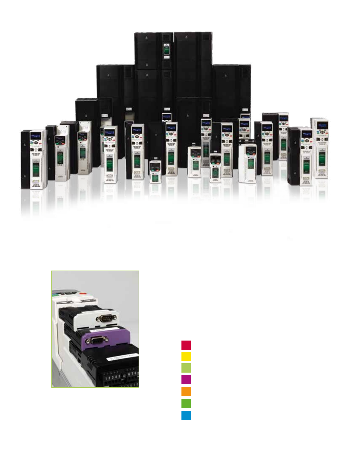
Unidrive M – the drive for industrial
applications
Unidrive M is a family of six variable speed drives designed for
industrial applications. Each Unidrive M model has been designed
for specic application needs identied through extensive market
research. Unidrive M is evolving the future of industry with the
latest drive technology which includes 21 patents granted and 42
patents pending.
Integrate, automate and communicate with
Unidrive M options
Unidrive M supports a wide range of option modules and
interface units which allow the drive to integrate seamlessly with
existing systems. Options include feedback, communications,
applications (onboard PLCs), I/O and enhanced safety features.
Unidrive M uses a high speed parallel bus between the drive and
SI modules, improving reaction time. Communications interfaces
are independently certied for conformance with the relevant
standards to ensure performance and interoperability.
MCi200/MCi210 options substantially extend Unidrive M’s
machine control capability using the latest generation of
microprocessor technology. These modules are congured using
the industry standard IEC61131-3 programing environment.
Combined with its onboard performance, this makes Unidrive M
the market-leading industrial drive.
2
www.emersonindustrial.com/automation
This guide is designed to give an overview of Unidrive M’s
comprehensive range of option modules, including:
• An explanation of their function
• Key specication details
• Compatibility with Unidrive M drives
• Terminal descriptions
INDEX
Machine Control pages 6 - 9
Safety pages 10 - 11
Communications pages 12 - 17
Feedback pages 18 - 20
Additional I/O page 21
Keypads page 22
Drive Interface Units pages 23
www.emersonindustrial.com/automation
3

Unidrive M Option Module Overview
The table below summarizes all the option modules that function with the Unidrive M product family drives. More detailed
information on each can be found later in this guide.
Unidrive M option module summary table
Option Typ e
System Integration (SI) Modules
MCi200
MCi210
SI-Applications Plus
SI-Safety
SI-Ethernet
SI-PROFINET
SI-EtherCAT
SI-CANopen
SI-PROFIBUS
SI-DeviceNet
SI-Encoder
SI-Universal Encoder
SI-I/O
Keypads
Fixed LED keypad
Fixed LED keypad with speed
reference potentiometer
CI-Keypad
Remote keypad
KI-Keypad
KI-Keypad RTC
Drive interface units
SD Card Adaptor
Smartcard
AI-Back-up Adaptor
AI-Smart Adaptor
AI-485 Adaptor
CI-485 Adaptor
KI-485 Adaptor
CT USB Comms cable
Machine Control
Safety
Communications
Feedback
Additional I/O
User interface
Back-up
Communications
Applicable to
M100 M200 M300 M400 M600 M700
•
•
•
• •
• • • • •
• • • • •
• • • • •
• • • • •
• • • • •
• • • • •
• •
• •
• • • • •
M100 M200
M101 M201
•
•
• • • • •
• •
• •
• •
• •
• • • •
• • • •
• • •
•
• •
•* •* •* •
M701
*also requires an adaptor
4
www.emersonindustrial.com/automation
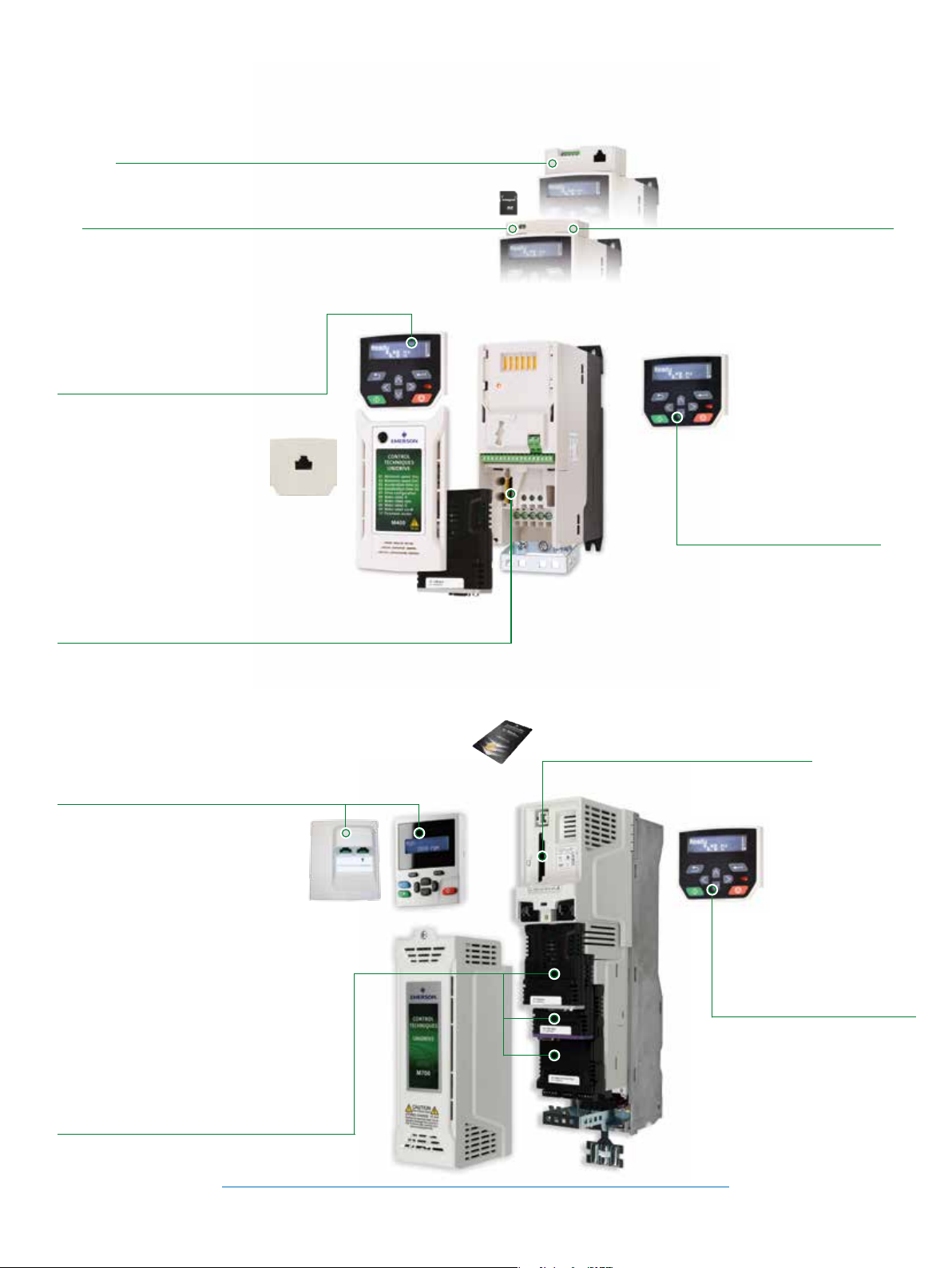
Option module interface locations on Unidrive M
M100 to M400
AI-485 Adaptor for RS485 communications (M200 to M400 only)
AI-Back-up Adaptor allows the drive to use an SD card for
parameter cloning and acts as an input for 24 V back-up
CI-Keypad - intuitive plain text multilingual
back-lit LCD keypad for rapid set-up and
superior diagnostics (M400 only)
Adaptor that allows the drive to
communicate via RS485
System Integration (SI) module slot for optional
communications and additional I/O (M200 to M400 only)
AI-Smart Adaptor contains built
in 4 GB memory for parameter
cloning and applications programs,
and an input for 24 V back-up
Optional IP66 (NEMA4) Remote
Keypad available for Panel
mounting (M200 to M700)
M600 to M700
Range of multi-language LCD keypads available
for rapid set-up and superior diagnostics; KI-485
Adaptor available for additional communications
via RS485 on Modbus RTU
System Integration (SI) module slots for
communications, I/O, additional feedback
devices and automation/motion controllers
(MCi)
• 3 slots on M600 and M700
Slot for Smartcard / SD card for parameter,
PLC and motion program storage
Optional IP66 (NEMA4) Remote
Keypad available for Panel
mounting (M200 to M700)
www.emersonindustrial.com/automation
5
MACHINE CONTROL
Machine Control Modules
Unidrive M’s MCi200 and MCi210 modules extend machine
control capability when combined with the Advanced Motion
Controller embedded in Unidrive M700. Enabling easy
connectivity of additional machine components and application
software, MCi200 and MCi210 create a complete application
solution. As a result of the highly exible plug-in option module
format, system design is streamlined by removing the need
for PLCs and additional external equipment. Machine control
is fast and easy to achieve thanks to Unidrive M’s user friendly
programming software - Machine Control Studio - utilizing the
industry-standard open IEC 61131-3 programming environment.
The MCi200 and MCi210 machine control modules provide:
High performance machine control – high speed
communications of 250 µs enables optimum performance.
High bandwidth – control multiple drive and motor axes thanks
to MCi210’s second Ethernet port.
Optimum ease of use – rapidly create machine control
programs with Unidrive M’s programming software, developed
with extensive human centred design research and based on the
industry-standard IEC 61131-3 programming environment.
Open environment – Standard IEEE 1588 Ethernet and IEC
61131 software enable open machine control programming,
boosting the choice of component connectivity.
Streamlined machine design – plug-in option module format
means less wiring, less physical space required and less nancial
cost, while increasing design simplicity.
User programming
The MCi200 and MCi210 modules are capable of running
Machine Control Studio programs. It is an integrated
development environment that supports all ve of the
programming languages of the IEC 61131-3 standard, including
Structured Text (ST), Ladder Diagram (LD), Function Block
Diagram (FBD), Sequential Function Chart (SFC) and Instruction
List (IL). Continuous Function Chart (CFC) is also supported.
Optimum connectivity
Simple integration with external components such as I/O, HMIs
and other networked drives can be achieved using Unidrive M’s
integrated standard Ethernet ports (with RTMoE or standard
protocols), or eldbuses supported by SI option modules (EtherCAT,
PROFINET, PROFIBUS, CANopen).
6
www.emersonindustrial.com/automation
MCi200 & MCi210
Build high performance systems and
productive machines
• MCi modules execute comprehensive programs that can
control multiple drives and motors simultaneously across realtime networks
• M700’s onboard Ethernet using RTMoE (Real Time Motion
over Ethernet) provides synchronization and communication
between drives using the Precision Time Protocol as dened by
IEEE1588 V2
• Performance is optimized by having a motion controller
embedded in each networked drive
MACHINE CONTROL
M100 M200 M300 M400 M600 M700
✓
The user has a number of tasks available to them as shown in the following table.
Task Interval
Initial
Freewheeling
Clock0
Clock1
Clock2
Clock3
Position
Event0
Event1
Event2
Event3
ErrorTask
The Clock and Position tasks are cyclic and will run at an interval set by the user. The Freewheeling task is the lowest priority task and will
run when processor resource allows.
MCi210 ensures higher performance by delivering:
• Two additional Ethernet ports with an internal switch
• Support for standard Ethernet protocols, along with RTMoE for
PTP (IEEE 1588) synchronization
• Modbus TCP/IP master (up to 5 nodes)
• Parallel interface with drive processor provides faster data
exchange
• Machine control over two segregated Ethernet networks
enables greater exibility in machine design
• Extends connectivity with 3 x digital inputs, 1 x digital output
and 1 x digital I/O
Executes once when the user program starts
No timebase
User-specied timebase from 1 ms to 24 hours in 1 ms increments
User-specied timebase from 250 μs to < 8 ms in 250 μs increments
No timebase. This task is triggered (e.g. by the Timer Unit, Ethernet cyclic data etc.)
No timebase. This task is triggered on a user program error
www.emersonindustrial.com/automation
7
8 7 6 5 4 3 2 1
1
4 536
2
B
A
1
4 536
2
MACHINE CONTROL
SF
CPU314C-2 DP
BF
DC5V
FRCE
RUN
STOP
PUSH
RUN
STOP
MRES
0
1
2
3
4
5
6
7
IN IN OUT
DI+2 DI+0
DI+1
D0+0
D0+1
DI8xDC24V
AI5/A02x12Bit
DI16/D016xDC24V
0
1
2
3
4
5
6
7
0
1
2
3
4
5
6
7
0
1
2
3
4
5
6
7
0
1
2
3
4
5
6
7
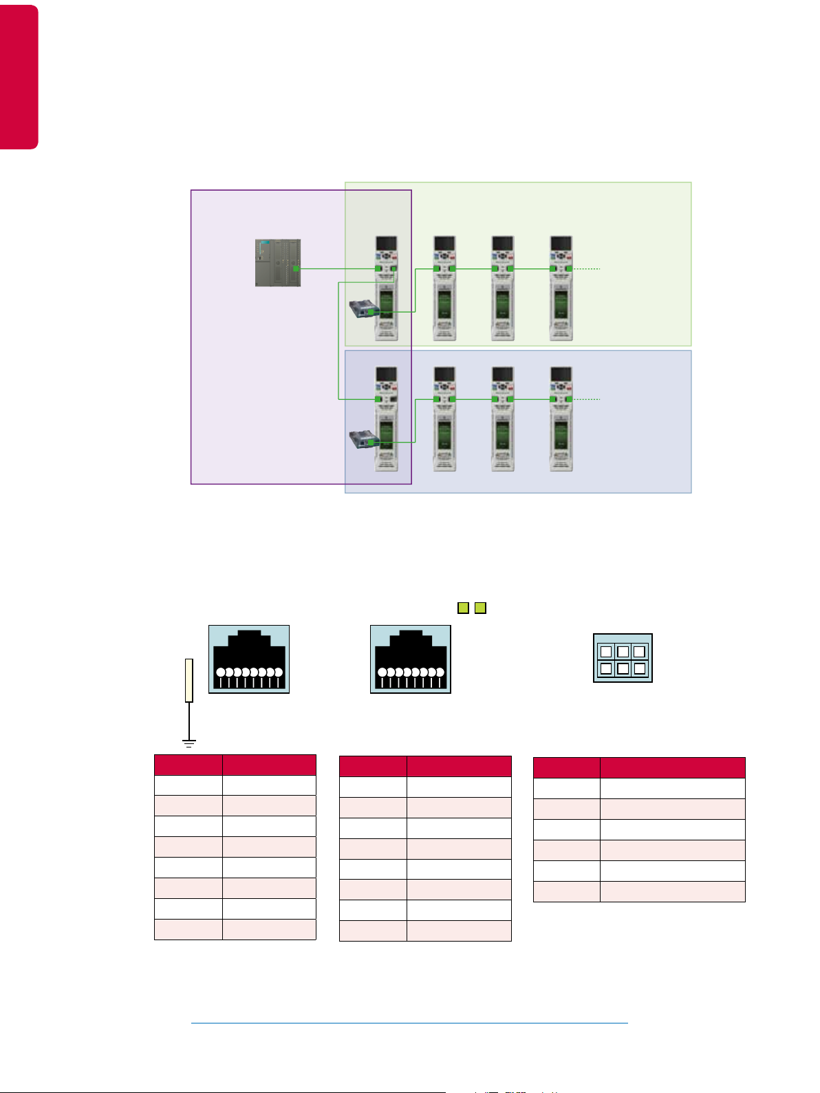
Segregated network control
Terminal descriptions
Network 1 Network 2
System
Controller
Machine 1
MCi
Controller
Network 3
Machine 2
MCi
Controller
Link / activity
indicators
Port A Port B Digital I/O
A
B
Spade
connector
8 7 6 5 4 3 2 1
Terminal Description
1 Transmit +
2 Transmit -
3 Receive +
4 N/A
5 N/A
6 Receive -
7 N/A
8 N/A
8 7 6 5 4 3 2 1
Terminal Description
1 Transmit +
2 Transmit -
3 Receive +
4 N/A
5 N/A
6 Receive -
7 N/A
8 N/A
Terminal Description
1 Digital input 1
2 Digital input 2
3 Digital input 3
4 Digital I/O 4
5 Digital output 5
6 0 V common
362
1
5
4
8
www.emersonindustrial.com/automation

SI-Applications Plus
SI-Applications Plus modules allow SyPTPro application programs
to be recompiled and executed with Unidrive M700 to enable rapid
and simple upgrade for Unidrive SP users. Applications comprising
networked Unidrive SP drives with SM-Applications using CTNet or
CTSync for real-time control can be quickly replaced with Unidrive
M and the SI-Applications Plus module without any compromise to
system performance.
Features include
• Enhanced high speed dedicated microprocessor
• 384 kB Flash memory for user program
• 80 kB user program memory
• EIA-RS485 port offering ANSI, Modbus-RTU follower and
master and Modbus-ASCII follower and master protocols
• CTNet high speed network connection offering up to 5
Mbit/s data rate
• Two 24 V digital inputs
• Two 24 V digital outputs
• Task based programming system for real-time control
• CTSync distributes a master position to multiple drives on a
network. Hardware synchronization of speed, position and
torque loops achieving a time base of 250 μs
MACHINE CONTROL
M100 M200 M300 M400 M600 M700
✓
Terminal descriptions
1 2 3 4 5
Terminal Function Description
1 0 V SC 0 V connection for EIA-RS485 port
2 /RX EIA-RS485 Receive line (negative). Incoming
3 RX EIA-RS485 Receive line (positive). Incoming
4 /TX EIA-RS485 Transmit line (negative). Outgoing
5 TX EIA-RS485 Transmit line (positive). Outgoing
6 CTNET A CTNet data line
7 CTNET
Shield
8 CTNET B CTNet data line
9 0 V 0 V connection for digital I/O
10 DIO Digital input 0
11 DI1 Digital input 1
12 DO0 Digital output 0
13 DO1 Digital output 1
Shield connection for CTNet
6 7 8
9 10 11 12 13
www.emersonindustrial.com/automation
9

Safety System Integration Module
S
I
L
3
Safety Integrity Level
M100 M200 M300 M400 M600 M700
SI-Safety
The SI-Safety module enhances the safety capability of Unidrive M for the protection of end users. The module also increases
machine productivity with safety features which reduce the frequency of machine power-downs. Ensuring machines achieve
stringent safety standards, SI-Safety can reduce machine size and cost by removing the need for external safety PLCs and other
components.
SAFETY
• Increase productivity: SI-Safety minimises downtime as its functionality enables a machine to slow-down or stop, removing the need
to power-down the machine after interruption.
• Enhanced user safety: Features including Safe Stop and Safe Operating Stop dramatically increase end user safety, as well as safe
machine operation with Safe Limited Speed and Safe Limited Position.
• Achieves the highest safety level: SI-Safety is approved by TUV as meeting SIL3, the highest safety level attainable for industrial
electrical components according to functional safety standards as IEC 61800-5-2.
Standard Safety Functions:
The following SIL3 safety functions dened by IEC 61800-5-2 are available with SI-Safety:
SAFETY
Safe Torque Off STO Prevents torque from being generated by the motor. This function is integrated within the
drive itself as standard
Safe Stop 1 SS1 Ensures a controlled stop with power available to the motor. Once the stop is achieved the
power is then removed.
Safe Stop 2 SS2 Ensures a controlled stop with power left available to the motor
Safe Limited Speed SLS Prevents the motor from exceeding a specied speed limit
Safe Limited Position SLP Monitors absolute position to ensure the motor operates within specied limits
Safe Brake Control SBC Provides a safe output signal to control an external safety brake
Safe Operating Stop SOS Prevents the motor from deviating from the stopped position
Safe Direction SDI Prevents the motor from moving in the unintended direction
Safe Limited Increment SLI Prevents the motor from exceeding the specied limit of position increment
Safe CAM SCA Provides a safe signal when the motor position is within a specied range
Safe Speed Monitor SSM Provides an indication when the motor speed is below a given limit
✓ ✓
Flexible programming environment
CTSafePro
CTSafePro unlocks the full safe PLC functionality within the
SI-Safety module. It allows users to combine elements to
develop their own safety function blocks to meet the specic
needs of more advanced applications.
Terminal descriptions
RJ45
Diagnostic
programming
Port
Connection
www.emersonindustrial.com/automation
I/O connection
10
1
10 17 (OV) 18 (+Ub)
9
Encoder 2
power
connection
Status LED
HDMI
Encoder
Safety Standards
The module is designed to meet the following safety standards:
• IEC and EN 61508: Functional safety of safety-related electric,
electronic and programmable electronic systems
• IEC and EN 62061: Safety of machinery, Functional safety
of safety-related electrical, electronic and programmable
electronic control systems
• ISO and EN ISO 13849-1: Safety of machinery - Safety-related
parts of control systems - Part 1: General principles for design
• IEC and EN 61800-5-2: Adjustable speed electrical power drive
systems - Part 5-2: Safety requirements - Functional

I/O Interface
Terminal Designation Function
1 SMF11 Digital IN SMF11
2 SMF12 Digital IN SMF12
3 SMF21 Digital IN SMF21
4 SMF22 Digital IN SMF22
5 SMF31 Digital IN SMF31
6 SMF32 Digital IN SMF32
7 SMF41 Digital IN SMF41
8 SMF42 Digital IN SMF42
9 E0.5 Digital IN E0.5
10 P1 Clocking output P1
11 P2 Clocking output P2
12 STO HISIDE output STO
13 SBC1 HISIDE output SBC1
14 SBC2 HISIDE output SBC2
15 A0.1 Signal and auxiliary output A0.1
16 A0.2 Signal and auxiliary output A0.2
17 L-ENC 1/2 Sensor power supply for sensor interface GND ENC 1/2
18 L+ENC2 Sensor power supply for sensor interface SUPPLY ENC2
SAFETY
Encoder interface HDMI
Pin Designation Encoder Function
1 A+(COS+)/DATA+ ENC1 Incremental track A+ / data wire DATA+
2 SHIELD
3 A-(COS-)/DATA- ENC1 Incremental track A- / data wire DATA-
4 B+(SIN+)/CLK+ ENC1 Incremental track B+ / data wire CLOCK+
5 SHIELD
6 B-(SIN-)/CLK ENC1 Incremental track B- / data wire CLOCK-
7 A+(COS+)/DATA+ ENC2 Incremental track A+ / data wire DATA+
8 SHIELD
9 A-(COS-)/DATA- ENC2 Incremental track A- / data wire DATA-
10 B+(SIN+)/CLK- ENC2 Incremental track B+ / data wire CLOCK+
11 SHIELD
12 B-(SIN)/CLK- Incremental track B- / data wire CLOCK-
13 L+ ENC1 Power supply for SUPPLY sensor interface
14 L+ ENC1 Power supply for SUPPLY sensor interface
15 L- ENC1/2 Power supply for GND sensor interface
16 L- ENC1/2 Power supply for GND sensor interface
17 L+ ENC2 Power supply for SUPPLY sensor interface
18 L+ ENC2 Power supply for SUPPLY sensor interface
19 NC
www.emersonindustrial.com/automation
11

Communications System Integration Modules
1 32
M100 M200 M300 M400 M600 M700
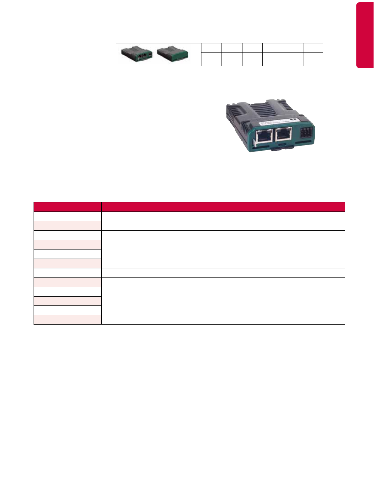
SI-Ethernet
* Does not support synchronous cyclic data exchange
SI-Ethernet supports real-time Ethernet (IEEE 1588 V2 Precision
Time Protocol), HTTP, SMTP, EtherNet/IP and Modbus TCP/IP. The
module can be used to provide high speed drive access, global
connectivity and integration with IT network technologies, such as
wireless networking.
Features include:
• Real-time Ethernet (IEEE 1588 V2 Precision Time Protocol),
Modbus TCP/IP, EtherNet/IP
• Network synchronization of less than 1 μs jitter (typically <200
ns)
COMMUNICATIONS
• 1 ms cycle time for synchronous cyclic data
• Bandwidth protection through a network gateway that
manages non-real-time Ethernet messages
• Master/follower and peer-to-peer communications capabilities
• Addressing is IP based
• Dual 100 BASE-TX RJ45 connectors with support for shielded
twisted pair, full-duplex 100 Mbps connectivity with auto
crossover correction
• Integrated switches allow for use of line networks i.e. daisy
chaining
• Both ports operate in full duplex mode as a network switch
• LED indication of network port activity
✓* ✓* ✓* ✓*
Terminal descriptions
Spade
connector
Terminal Description
1 Transmit +
2 Transmit -
3 Receive +
4 N/A
5 N/A
6 Receive -
7 N/A
8 N/A
✓
Port A Port B
8 7 6 5 4 3 2 1 8 7 6 5 4 3 2 1
Terminal Description
1 Transmit +
2 Transmit -
3 Receive +
4 N/A
5 N/A
6 Receive -
7 N/A
8 N/A
Link / activity
indicators
A
B
COMMUNICATIONS
12
Assembly line
www.emersonindustrial.com/automation

SI-PROFINET
1 32
M100 M200 M300 M400 M600 M700
✓ ✓ ✓ ✓ ✓
SI-PROFINET allows Unidrive M to communicate and interface with
PROFINET PLCs and networks.
Features include:
• Dual 100 BASE-TX RJ45 connectors with support for shielded
COMMUNICATIONS
twisted pair, full-duplex 100 Mbps connectivity with auto
crossover correction
• Integrated switches allow for use of line networks i.e. daisy
chaining
• Both ports operate in full duplex mode as a network switch
• PROFINET Real-time class RT_Class_1 and conformance
class A
• Cycle times from 2 ms to 512 ms specied during conguration
• Automatic device replacement using the LLDP and DCP
protocols
• LED indication of network port activity
• Up to 64 cyclic I/O module slots (maximum of 32 in and 32 out)
congured by network conguration tool and GSDML le
• Identication and maintenance functions I&M0 to I&M4
supported
Terminal descriptions
Port A Port B
Spade
connector
8 7 6 5 4 3 2 1 8 7 6 5 4 3 2 1
Terminal Description
1 Transmit +
2 Transmit -
3 Receive +
4 N/A
5 N/A
6 Receive -
7 N/A
8 N/A
Link / activity
indicators
A
B
Terminal Description
1 Transmit +
2 Transmit -
3 Receive +
4 N/A
5 N/A
6 Receive -
7 N/A
8 N/A
COMMUNICATIONS
www.emersonindustrial.com/automation
13

1 32
SI-EtherCAT
M100 M200 M300 M400 M600 M700
✓ ✓ ✓ ✓ ✓
SI-EtherCAT allows Unidrive M to connect and interface with
EtherCAT networks.
Features include:
• Up to 64,535 nodes on a segment
• Data rate of 100 Mbps (100BASE-TX)
• Update 40 axes in 250 μs (assuming 2 words command data
and 3 words feedback data per axis, a control word and basic
cyclic synchronization data)
• Jitter of less than 1 μs with Unidrive M600 to M700
• Non-cyclic data using the CoE mailbox
• CANopen DS-402 prole supported (drives and motion control)
COMMUNICATIONS
• LED indication of network port activity
Terminal descriptions
Port A Port B
Spade
connector
8 7 6 5 4 3 2 1 8 7 6 5 4 3 2 1
Terminal Description
1 Transmit +
2 Transmit -
3 Receive +
4 N/A
5 N/A
6 Receive -
7 N/A
8 N/A
Link / activity
indicators
A
B
Terminal Description
1 Transmit +
2 Transmit -
3 Receive +
4 N/A
5 N/A
6 Receive -
7 N/A
8 N/A
14
Bottle lling line
www.emersonindustrial.com/automation

SI-CANopen
M100 M200 M300 M400 M600 M700
✓ ✓ ✓ ✓ ✓
Unidrive M’s CANopen interface module supports various
proles including several drive proles. SI-CANopen has
been designed to offer optimum exibility: in particular the
process data objects (PDO) numbering system has been
specically designed to offer maximum versatility while
maintaining conformance to CiA specications.
Features include:
• Supported data rates (bits/s): 1 M, 800 k, 500 k,
250 k,125 k, 100 k and 50 k
• 4 transmit and 4 receive PDOs A, B, C and D supported
• Independently congurable transmit and receive PDO
numbers (1-511) for maximum application exibility
• All synchronous and asynchronous PDO communication
modes supported
• Total of 32 bytes (16 words) in each direction using PDOs
(4 TxPDOs of 64 bits and 4 RxPDOs of 64 bits)
• Service Data Objects (SDO) provide access to all drive
and option module parameters
• Consumer heartbeat
• Emergency message completed ag
• RxPDO, SYNC and missed heartbeat event handling
• RxPDO event triggers
• TxPDO event triggers
• Object association for un-dened DSP-402 objects
• +24 V back-up power supply capability
Terminal descriptions
1 2 3 4 5
+24 V external power supply (red)
CAN-H positive data line (white)
Cable screen (braided shield)
CAN-L negative data line (blue)
0 V external power supply (black)
COMMUNICATIONS
www.emersonindustrial.com/automation
15

SI-PROFIBUS
M100 M200 M300 M400 M600 M700
✓ ✓ ✓ ✓ ✓
COMMUNICATIONS
Unidrive M’s PROFIBUS-DP interface module enables follower
connectivity. It is possible to use multiple SI-PROFIBUS modules
or a combination of SI-PROFIBUS and other option module types
to add additional functionality such as extended I/O, gateway
functionality or additional PLC features.
Features include:
• Supported data rates (bits/s): 12 M, 6.0 M, 3.0 M, 1.5 M, 500 k,
187.5 k, 93.75 k, 45.45 k, 19.2 k, 9.6 k
• Maximum of 32 input and 32 output cyclic data words
supported
• PROFIdrive prole (V2 & V4) supported
• Non-cyclic data channel supported
COMMUNICATIONS
• Parallel acyclic/cyclic data communication
M100 M200 M300 M400 M600 M700
SI-DeviceNet
SI-DeviceNet enables follower connectivity. It is possible to use
multiple SI-DeviceNet modules or a combination of SI-DeviceNet
and other option module types to provide additional functionality
such as extended I/O, gateway functionality or additional PLC
features.
Features include:
• Supported data rates (bits per s): 500 k, 250 k, 125 k
• 1 to 28 input/output polled data words supported
• Explicit communications (non-cyclic) provide access to all
drive parameters
• 8 pre-dened DeviceNet proles supported
Terminal descriptions
RxD/TxD-P (Red)
CNTR-P
0 V ISO
(for termination only)
9 7
RxD/TxD-N (Green)
+5 V ISO
(for termination only)
✓ ✓ ✓ ✓ ✓
Terminal descriptions
1 2 3 4 5
1
25 4 3
8 6
+24 V external power supply (red)
CAN-H positive data line (white)
Cable screen (braided shield)
CAN-L negative data line (blue)
0 V external power supply (black)
Cable screen
(braided shield)
Shell
16
www.emersonindustrial.com/automation

COMMUNICATIONS
www.emersonindustrial.com/automation
Metal rolling machine
17

Feedback System Integration Modules
M100 M200 M300 M400 M600 M700
SI-Encoder
Terminal descriptions
SI-Encoder has an incremental encoder input to provide Closed loop
Rotor Flux Control for induction motors (RFC-A) on M600 and an
additional encoder input on M700.
Features include:
• Supports AB quadrature encoders without marker pulse
1
*
the encoder cable can be independently connected to
0 V without requiring dual wire (twin) crimp ferrules.
This provides a system which is easier to wire and debug
electrical noise issues.
✓ ✓
1 2 3 4 5 6 7
Pin Number Function
1 A
2 /A
3 B
4 /B
5 Power Supply +
6 Power Supply 0 V *
7 Power Supply 0 V *
: Two 0 V terminals are provided so that the shield of
1
1
FEEDBACK
SI-Universal Encoder
The dual encoder port on the Unidrive M700 supports two position
feedback interfaces, P1 & P2, through a 15-way high density
D-type connector. The SI-Universal Encoder complements this by
enabling additional input and output formats to be used that could
not otherwise be supported by the single 15 pin connector. It also
provides Closed loop Rotor Flux Control for induction motors (RFC-A)
on M600.
Features include:
Support for:
• SinCos with communications
• SinCos with or without commutation
• Quadrature incremental with or without commutation
• Pulse and direction
• SSI and EnDat
The module also provides a simulated encoder output that can be
programmed to operate in the following modes:
• Quadrature incremental
• Pulse and direction
• SSI
The module also incorporates high speed inputs for position capture.
M100 M200 M300 M400 M600 M700
✓ ✓
Functions
P1 Position
feedback interface
AB Servo
FD Servo
FR Servo
SC Servo
AB
FD
FR
SC
SC Hiperface
SC EnDat
SC SSI
EnDat
SSI
P2 Position
feedback interface
None None
AB, FD, FR, EnDat,
SSI
None Full
AB, FD, FR (No Z
marker pulse input)
EnDat, SSI
None
AB, FD, FR None
EnDat, SSI
None Full
Encoder simulation
outputs
None
None
No Z marker pulse
output
No Z marker pulse
output
18
www.emersonindustrial.com/automation

Position feedback device interface connections
The SI-Universal Encoder has two position feedback interfaces and an encoder simulation output on the 15-way D-type. The
availability of the encoder simulation output and the 2nd position interface (P2) depends on the feedback device type selected
for the 1st position interface (P1) as some feedback devices use all pins of the 15-way D-type.
The drive supports the following encoder types:
Position feedback device type Drive name
Quadrature incremental encoders with or without marker pulse AB
Frequency and direction incremental encoders with or without marker pulse FD
Forward / reverse incremental encoders with or without marker pulse FR
Quadrature incremental encoders with or without marker pulse and UVW commutation signals for absolute position
for permanent magnet motors
Frequency and direction incremental encoders with or without marker pulse and UVW commutation signals for
absolute position for permanent magnet motors
Forward / reverse incremental encoders with or without marker pulse and UVW commutation signals for absolute
position for permanent magnet motors
Sincos incremental encoders with or without marker pulse SC
Sick sincos encoders with Hiperface communications for absolute position SC Hiperface
Heidenhain EnDat 2.1 or 2.2 communication only encoders EnDat
Heidenhain sincos encoders with EnDat communication for absolute position SC EnDat
SSI encoders (Gray code or binary) SSI
Sincos encoders with SSI comms for absolute position (Gray code or binary) SC SSI
Sincos incremental encoders with or without marker pulse and UVW commutation signals for absolute position for
permanent magnet motors
AB Servo
FD Servo
FR Servo
SC Servo
FEEDBACK
The marker inputs can be used without their associated position feedback as freeze trigger inputs, therefore these are present
where possible even if the associated incremental or SINCOS position feedback is not possible. The table below gives the
connection functions associated with the codes used.
Connection Function Connection Definition
Position Interface inputs
A A input for AB, or AB Servo encoders, F input for FD, FD Servo, FR or FR Servo encoders
B B input for AB, or AB Servo encoders, D input for FD or FD Servo encoders, R input for FR or FR
Z Z input for AB, AB Servo, FD, FD Servo, FR, FR Servo, SC encoders, Freeze input
U, V, W Commutation signals for AB Servo, FD Servo, FR Servo, or SC Servo
Cos, Sin Cosine and Sine inputs for SC, SC EnDat, SC Hiperface, SC SSI or SC Servo encoders
D Data input/output for SC EnDat, SC Hiperface or EnDat encoders
Clk Clock output for SC EnDat, SC SSI, EnDat or SSI encoders
Encoder Simulation Output
AOut A output for AB mode, F output for FD or FR modes, Data output for SSI Gray or SSI Binary
BOut B output for AB mode, D output for FD or FR modes, Clock input for SSI Gray or SSI Binary
Zout Z output for AB, FD or FR modes
Power Supply and Temperature Measurement
PS1 Power supply output (13 = Supply, 14 = 0 V)
Th Temperature measurement input
Servo encoders
Data input for SC SSI, SSI encoders
modes
modes
www.emersonindustrial.com/automation
19

Terminal descriptions
1 2 3 4 5
6 7 8 9 10
The table below shows the functions that can be provided simultaneously, along with the
connections required for each combination of functions.
D-type connector
Functions Connections
FEEDBACK
P1 Position feedback
interface
AB Servo
FD Servo
FR Servo
SC Servo Cos1 Sin1 Z1 U1 V1 W1 PS1 Th
AB, FD, FR AB, FD, FR A1 B1 Z1 A2 B2 Z2 PS1 Th
AB, FD, FR EnDat, SSI A1 B1 Z1 D2 Clk2 Z2 PS1 Th
AB, FD, FR Full A1 B1 Z1 AOut BOut ZOut PS1 Th
SC AB, FD, FR Cos1 Sin1 Z1 A2 B2 Z2 PS1 Th
SC EnDat, SSI Cos1 Sin1 Z1 D2 Clk2 Z2 PS1 Th
SC Full Cos1 Sin1 Z1 AOut BOut ZOut PS1 Th
SC Hiperface AB, FD, FR Cos1 Sin1 D1 A2 B2 Z2 PS1 Th
SC Hiperface EnDat, SSI Cos1 Sin1 D1 D2 Clk2 Z2 PS1 Th
SC Hiperface Full Cos1 Sin1 D1 AOut BOut ZOut PS1 Th
SC EnDat
SC SSI
SC EnDat
SC SSI
SC EnDat
SC SSI
EnDat, SSI AB, FD, FR D1 Clk1 Z1 A2 B2 Z2 PS1 Th
EnDat, SSI EnDat, SSI D1 Clk1 Z1 D2 Clk2 Z2 PS1 Th
EnDat, SSI Full D1 Clk1 Z1 AOut BOut ZOut PS1 Th
EnDat, SSI EnDat, SSI No Z marker pulse D1 Clk1 D2 AOut BOut Clk2 PS1 Th
P2 Position feedback
interface
AB, FD, FR No Z Cos1 Sin1 D1 A2 B2 ClK1 PS1 Th
EnDat, SSI Cos1 Sin1 D1 D2 Clk2 Clk1 PS1 Th
Encoder Simulation
Output
No Z marker pulse Cos1 Sin1 D1 AOut BOut Clk1 PS1 Th
1/2 3/4 5/6 7/8 9/10 11/12 13/14 15
A1 B1 Z1 U1 V1 W1 PS1 Th
25104 3 1
79 8 6
1215 14 13 11
Blue text indicates P1 interface connections|Green text indicates P2 interface connections|Red text indicates encoder simulation
output connections| A1 means A = Pin1, A\ = Pin2
Screw terminal connector
Terminal Description
1 24 V Freeze input
2 0 V
3 (7) Encoder simulation output: A, F or DATA | P2 input: A, F, DATA
4 (8) Encoder simulation output: A\, F\ or DATA\ | P2 input: A\, F\, DATA\
5 (9) Encoder simulation output: B, F, D or Clock | P2 input: B, F, D, Clock
6 (10) Encoder simulation output: B\, F\, D\ or Clock\ | P2 input: B\, F\, D\, Clock\
7 0 V
8 (11) Encoder simulation output: Z | P2 input: Z
9 (12) Encoder simulation output: Z\ | P2 input: Z\
10 (13) Power supply output
1 2 3 4 5
6 7 8 9 10
The termination resistors are
always enabled on the P2 position
interface. Wire break detection is
not available when using AB, FD or
FR position feedback device types
on the P2 position interface.
The value in brackets corresponds
to the pin on the 15-way D-type to
which this terminal is connected.
20
www.emersonindustrial.com/automation

Additional I/O System Integration Modules
M100 M200 M300 M400 M600 M700
SI-I/O
✓ ✓ ✓ ✓ ✓
Unidrive M’s extended I/O interface module increases the number
of I/O points on a drive. All connections from the option module
to the drive are made via the drive connector. Connections from
external equipment to the SI-I/O are made via a 3-way pluggable
screw connector for the two relays and an 11-way pluggable screw
connector for the digital and analog I/O.
Features include:
• 4 x Digital inputs/outputs
• 3 x Analog inputs (default) / Digital inputs
• 1 x Analog output (default)* / Digital input
• 2 x Relays
Digital I/O
By default, the SI-I/O Module is set up for four programmable
digital inputs/outputs. By conguring the analog I/O as
digital inputs, it is possible for the SI-I/O module to have four
programmable inputs/outputs and also four digital inputs.
The functionality of these terminals is as follows:
• The logic sense selected can be positive (default) or negative
• The logic state of each input is monitored by a read-only
parameter
• The logic state can be inverted
• The digital input can be programmed to any suitable
destination bit parameter
• The digital output can be sourced from any suitable bit
parameter
• The outputs can operate either as a push-pull or an open
collector output
The SI-I/O has a maximum output current of 250 mA at 24 V
across all four digital outputs.
Analog I/O
By default, the SI-I/O is set-up for three single-ended analog
inputs and one analog output or one high resolution* differential
analog input*, one single-ended analog input and one analog
output.
Analog inputs 1 and 2 can only be congured as ±10 Vdc voltage
inputs or digital inputs. When both are congured as analog
voltage inputs, they can be used as a single high resolution
differential analog input.
Analog input 3 can operate in voltage mode (±10 Vdc), current
mode (0 to 20 mA) or as a digital input.
Analog output 1* can operate in voltage mode (±10 Vdc),
current mode (0 to 20 mA) or as a digital input.
Relays
The two relays can be used to convey the logic state of any
suitable parameter to external equipment. The logic state is
processed as follows:
• A suitable source parameter is assigned to each relay
• The logic state can be inverted
• The state of the relay is monitored by a parameter
ADDITIONAL I/O
Terminal descriptions
PL1
Terminal Function
1 0 V common
2 Digital input/output 1
3 Digital input/output 2
4 Digital input/output 3
5 Digital input/output 4
6 0 V common
7 Analog input 1/digital input 5
8 Analog input 2/digital input 6
9 Analog input 3/digital input 7
10 0 V common
11 Analog output 1/digital input 8
* Only supported by M600 and M700
6 7 8 9 10 111 2 3 4 5
Terminal Function
21 Relay 1
22 Relay common
23 Relay 2
www.emersonindustrial.com/automation
21 22 23
PL2
21

Keypads
Unidrive M’s range of keypad options is hot-swappable and is designed to enhance ease of use. From easy commissioning to rapid
diagnostics, enhanced usability is achieved by a range of keypad options including plain text LCD display, support of multiple
languages and exible mounting options.
Typ e Benefit M100 M200 M300 M400 M600 M700
Fixed LED keypad
Fixed LED
keypad with
speed reference
potentiometer
CI-Keypad
Remote keypad
KI-Keypad
KI-Keypad RTC
Simple LED keypad tted as standard for
quick and easy commissioning and use.
Simple LED keypad with user friendly
speed reference potentiometer for
convenient speed control.
Intuitive plain text, multi-language LCD
keypad for rapid set-up and superior
diagnostics maximizes machine up-time.
All the features of the CI-Keypad LCD, but
remote mountable. This allows exible
mounting on the outside of a panel and
meets IP66 (NEMA 4).
Plain text, multi-language LCD keypad
with up to four lines of text for in-depth
parameter and data descriptions, for an
enhanced user experience.
All the features of the KI-Keypad, but with
battery operated real-time clock. This
allows accurate time stamping of events,
aiding diagnostics.
• • •
M101 M201
•
• • • • •
• •
• •
Drive interface units
Back-up
M100 M200 M300 M400 M600 M700
AI-Back-up Adaptor
Port adaptor that allows the drive to use an SD card for parameter cloning, and an input for 24 V back-up.
SD card
KEYPADS
Unidrive M uses readily available SD cards for quick and easy parameter and program storage. SD cards provide a large memory
capability allowing a complete system reload if required.
24 Vdc supply
+24 V 0 V
The 24 Vdc supply connected to the +24 V supply terminals on the AI-Back-up Adaptor and Smart Adaptor provides the following
functions:
• Back-up power supply to keep the control circuits of the drive powered-up when the line power supply is removed. Fieldbus
modules and serial communications can continue to operate.
• Clone or load parameters when the line power supply is not available. The keypad can be used to set-up parameters.
22
✓ ✓ ✓ ✓
www.emersonindustrial.com/automation

M100 M200 M300 M400 M600 M700
AI-Smart Adaptor
Contains built-in 4 GB memory for parameter cloning and applications programs, and an input for 24 V back-up
✓ ✓ ✓ ✓
Smartcard
www.controltechniques.com
The optional Smartcard memory device can be used to back-up parameter sets and PLC programs, as well as copying them from
one drive to another, including from a Unidrive SP. It also allows:
• Simplied drive maintenance and commissioning
• Quick set-up for sequential build of machines
• Upgrades to be stored on a Smartcard and sent to the customer for installation
SD-Smartcard Adaptor
Conversion device that allows an SD card to be inserted into the Smartcard slot, for parameter cloning and application programs.
M100 M200 M300 M400 M600 M700
✓ ✓
M100 M200 M300 M400 M600 M700
✓ ✓
Communications
AI-485 Adaptor
Adaptor that allows the drive to communicate via RS485 using Modbus RTU can be used to connect remote keypad.
Terminal descriptions
PL2
1 2 3 4 5 6
Terminal Function
1 0V
2 RX\ TX\
3 RX TX
4 120 Ω termination resistor
5 TX Enable
6 +24 V (100 mA)
PL2
M100 M200 M300 M400 M600 M700
✓ ✓ ✓
PL1
8 7 6 5 4 3 2 1
Terminal Function
1 120 Ω Termination resistor
2 RX TX
3 0V
4 +24 V (100 mA)
5 Not connected
6 TX enable
7 RX\ TX\
8 RX\ TX\ (if termination resistors are required, link to pin 1)
PL1
M100 M200 M300 M400 M600 M700
CI-485 Adaptor
Port adaptor that allows the drive to communicate via RS485 on Modbus RTU. This can be used to connect the Remote keypad.
M100 M200 M300 M400 M600 M700
KI-485 Adaptor
Allows the drive to communicate via RS485 on Modbus RTU. This is commonly used for programming if the drive has no keypad and is
recommended for use with the Remote keypad.
CT USB Comms cable
The USB Comms cable allows the drive to connect to a PC for use with Unidrive M’s PC tools
www.emersonindustrial.com/automation
✓
✓ ✓
DRIVE INTERFACE UNITS
23

Connect with us at:
twitter.com/ctandls
facebook.com/ctandls
youtube.com/controltechniquesandleroysomer
theautomationengineer.com (blog)
P.N. 0778-0084-05 01/16
www.emersonindustrial.com/automation
© Emerson 2015. The information contained in this brochure is for guidance only and does not form part of
any contract. The accuracy cannot be guaranteed as Emerson have an ongoing process of development and
reserve the right to change the specication of their products without notice.
Control Techniques Limited. Registered Ofce: The Gro, Newtown, Powys SY16 3BE. Registered in England
and Wales. Company Reg. No. 01236886.
Moteurs Leroy-Somer SAS. Headquarters: Bd Marcellin Leroy, CS 10015, 16915 Angoulême Cedex 9, France.
Share Capital: 65 800 512 €, RCS Angoulême 338 567 258.
 Loading...