

Control Techniques Unidrive 1201, UNI1204, Unidrive 1202, Unidrive 1203, Unidrive 1204 User Manual
...Page 1
EF
www.controltechniques.com
User Guide
Unidrive
Model sizes 1 to 5
Universal Variable Speed AC Drive
for induction and servo motors
Part Number: 0460-0083-09
Issue Number: 9
Page 2

General Information
The manufacturer accepts no liability for any consequences resulting from inappropriate, negligent or incorrect
installation or adjustment of the optional operating parameters of the equipment or from mismatching the variable speed
drive with the motor.
The contents of this guide are believed to be correct at the time of printing. In the interests of a commitment to a policy
of continuous development and improvement, the manufacturer reserves the right to change the specification of the
product or its performance, or the contents of the guide, without notice.
All rights reserved. No parts of this guide may be reproduced or transmitted in any form or by any means, electrical or
mechanical including photocopying, recording or by an information storage or retrieval system, without permission in
writing from the publisher.
Drive software version
This product is supplied with the latest version of user-interface and machine control software. If this product is to be
used in a new or existing system with other drives, there may be some differences between their software and the
software in this product. These differences may cause this product to function differently. This may also apply to drives
returned from a Control Techniques Service Centre.
If there is any doubt, contact a Control Techniques Drive Centre.
Environmental statement
Control Techniques is committed to minimising the environmental impacts of its manufacturing operations and of its
products throughout their life cycle. To this end, we operate an Environmental Management System (EMS) which is
certified to the International Standard ISO 14001. Further information on the EMS, our Environmental Policy and other
relevant information is available on request, or can be found at www.greendrives.com.
The electronic variable-speed drives manufactured by Control Techniques have the potential to save energy and
(through increased machine/process efficiency) reduce raw material consumption and scrap throughout their long
working lifetime. In typical applications, these positive environmental effects far outweigh the negative impacts of product
manufacture and end-of-life disposal.
Nevertheless, when the products eventually reach the end of their useful life, they can very easily be dismantled into their
major component parts for efficient recycling. Many parts snap together and can be separated without the use of tools,
whilst other parts are secured with conventional screws. Virtually all parts of the product are suitable for recycling.
Product packaging is of good quality and can be re-used. Large products are packed in wooden crates, whilst smaller
products come in strong cardboard cartons which themselves have a high recycled fibre content. If not re-used, these
containers can be recycled. Polyethylene, used on the protective film and bags for wrapping product, can be recycled in
the same way. Control Techniques' packaging strategy favours easily-recyclable materials of low environmental impact,
and regular reviews identify opportunities for improvement.
When preparing to recycle or dispose of any product or packaging, please observe local legislation and best practice.
Copyright © August 2003 Control Techniques Drives Limited
Issue Number: 9
Software: V03.02.12 onwards
Page 3
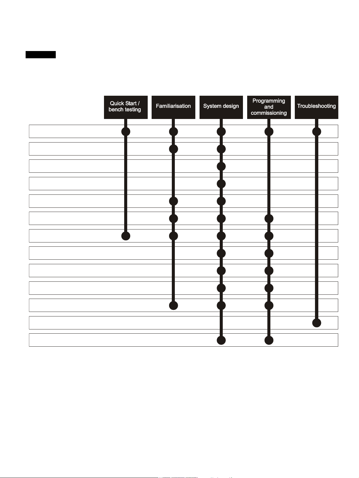
How to use this User Guide
This User Guide provides complete information for installing and operating a Unidrive from start to finish.
The information is in logical order, taking the reader from receiving the drive through to fine tuning the performance.
NOTE
There are specific safety warnings throughout this guide, located in the relevant sections. In addition, Chapter 1 Safety
Information on page 7 contains general safety information. It is essential that the warnings are observed and the
information considered when working with or designing a system using the drive.
This map of the user guide helps to find the right sections for the task you wish to complete:
1 Safety information
2 Product information
3 Mechanical installation
4 Electrical installation
5 Getting started
6 Menu 0
7 Running the motor
8 Optimisation
9 Macros
10 Advanced parameters
11 Technical data
12 Diagnostics
13 UL listing information
Page 4

Contents
Declaration of Conformity ................... 6
1 Safety Information .................................7
1.1 Warnings, Cautions and Notes .............................7
1.2 Electrical safety - general warning ........................7
1.3 System design and safety of personnel ................7
1.4 Environmental limits ..............................................7
1.5 Compliance with regulations .................................7
1.6 Motor .....................................................................7
1.7 Adjusting parameters ............................................7
2 Product Information ..............................8
2.1 Ratings ..................................................................8
2.2 Model number .......................................................8
2.3 Nameplate description - drive identification ..........9
2.4 Model variants .......................................................9
2.5 Operating modes .................................................10
2.6 Drive features ......................................................11
2.7 Option Modules ...................................................12
2.8 More information .................................................12
2.9 Items supplied with the drive ...............................13
3 Mechanical Installation .......................14
3.1 Safety information ...............................................14
3.2 Planning the installation ......................................14
3.3 Terminal cover removal .......................................14
3.4 Ingress protection ................................................15
3.5 Option module fitting / removal ...........................15
3.6 Mounting methods ...............................................16
3.7 Enclosure ............................................................24
3.8 Ventilation ...........................................................26
3.9 Baffle plates ........................................................28
3.10 Ambient temperature ...........................................28
3.11 RFI filters .............................................................29
3.12 Power terminals ..................................................35
3.13 Routine maintenance ..........................................36
4 Electrical Installation ...........................37
4.1 Power connections ..............................................37
4.2 AC supply requirements ......................................40
4.3 Supplying the drive with DC / DC bus paralleling 40
4.4 Ratings ................................................................40
4.5 Output circuit and motor protection .....................41
4.6 Braking ................................................................43
4.7 Ground leakage ...................................................44
4.8 EMC (Electromagnetic compatibility) ..................44
4.9 Control connections ............................................49
4.10 Encoder connections ...........................................54
4.11 Configuring a Unidrive size 5 system ..................56
5 Getting Started .................................... 58
5.1 Understanding the display .................................. 58
5.2 Keypad operation ............................................... 58
5.3 Menu structure ................................................... 59
5.4 Advanced keypad functions ............................... 60
5.5 Menu 0 ............................................................... 60
5.6 Advanced menus ............................................... 60
5.7 Changing the operating mode ............................ 61
5.8 Saving parameters ............................................. 61
5.9 Defaulting the drive ............................................ 61
5.10 Parameter security ............................................. 62
5.11 Serial Communications ...................................... 63
6 Menu 0 ................................................. 64
6.1 Single line descriptions ...................................... 64
6.2 Menu 0 full descriptions ..................................... 72
7 Running the motor .............................. 81
7.1 Quick start set-up ............................................... 81
7.2 Quick Start commissioning ................................. 84
7.3 Quick start P.C. commissioning (UniSoft /
VTCSoft) ............................................................ 87
8 Optimisation ........................................ 92
8.1 Motor map parameters ....................................... 92
8.2 Current limits ...................................................... 98
8.3 Motor thermal protection .................................... 99
8.4 Switching frequency ........................................... 99
8.5 High speed operation ......................................... 99
9 Macros ............................................... 101
9.1 Introduction ...................................................... 101
9.2 How to load a macro ........................................ 102
9.3 Macro terminal connection changes ................ 102
9.4 Macro logic diagrams and Menu 0 parameter
changes ............................................................ 106
9.5 Unidrive VTC macro differences ...................... 122
4 Unidrive User Guide
www.controltechniques.com Issue Number: 9
Page 5

10 Advanced Parameters ......................123
10.1 Menu 1: Speed references and limits ...............124
10.2 Menu 2: Ramps (accel. / decel.) .......................128
10.3 Menu 3: Speed feedback / frequency slaving ...131
10.4 Menu 4: Current control ....................................135
10.5 Menu 5: Machine control ...................................139
10.6 Menu 6: Sequencing logic .................................143
10.7 Menu 7: Analog I/O ...........................................145
10.8 Menu 8: Digital I/O ............................................148
10.9 Menu 9: Programmable logic ............................152
10.10 Menu 10: Status flags / trip log .........................155
10.11 Menu 11: Menu 0 customisation / drive specific
ratings ...............................................................156
10.12 Menu 12: Programmable thresholds .................157
10.13 Menu 13: Digital lock / orientation .....................160
10.14 Menu 14: Programmable PID function ..............166
10.15 Menu 15: Regen ...............................................169
10.16 Menu 16 Small option module set-up ...............171
10.17 Menu 17: Large option module set-up ..............179
10.18 Menu 18: Application menu 1 ...........................179
10.19 Menu 19: Application menu 2 ...........................180
10.20 Menu 20: Large option module .........................180
10.21 Unidrive VTC parameter range and default
differences ........................................................181
10.22 Advanced Features ...........................................182
11 Technical Data ...................................190
11.1 Drive ..................................................................190
11.2 Optional RFI filters ............................................197
12 Diagnostics ........................................198
12.1 Trip indications ..................................................198
12.2 Alarm indications ...............................................204
12.3 Status indications ..............................................204
12.4 Displaying the trip history ..................................204
13 UL Listing Information ......................205
13.1 AC supply specification .....................................205
13.2 Maximum continuous output current .................205
13.3 Safety label .......................................................205
Index ...................................................206
Unidrive User Guide 5
Issue Number: 9 www.controltechniques.com
Page 6
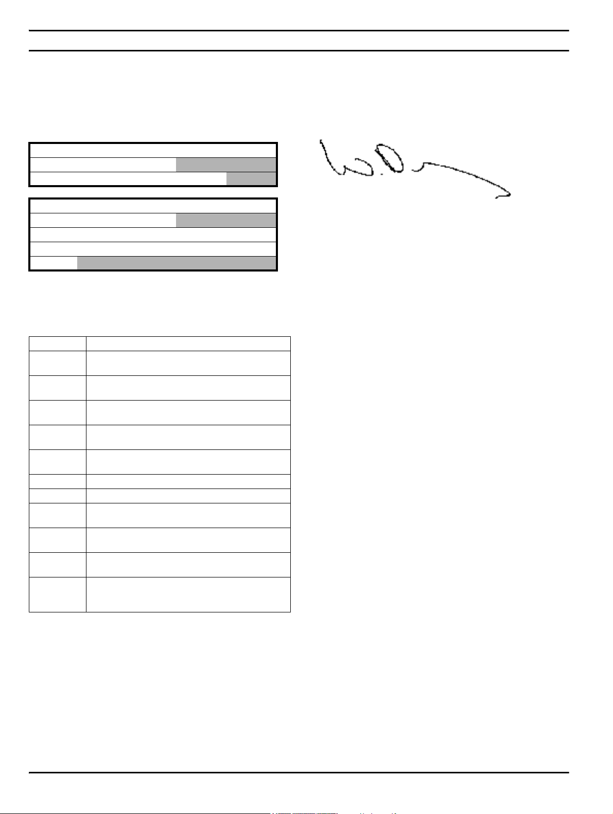
Declaration of Conformity
Control Techniques Ltd
The Gro
Newtown
Powys
UK
SY16 3BE
UNI1201 UNI1202 UNI1203 UNI1204 UNI1205
UNI2201 UNI2202 UNI2203
UNI3201 UNI3202 UNI3203 UNI3204
UNI1401 UNI1402 UNI1403 UNI1404 UNI1405
UNI2401 UNI2402 UNI2403
UNI3401 UNI3402 UNI3403 UNI3404 UNI3405
UNI4401 UNI4402 UNI4403 UNI4404 UNI4405
UNI5401
The AC variable speed drive products listed above, including the VTC,
LFT (all sizes) and REGEN (UNI3401 to UNI4405 only) variants, have
been designed and manufactured in accordance with the following
European harmonised, national and international standards:
EN 60249 Base materials for printed circuits
IEC326-1
IEC326-5
IEC326-6
IEC664-1
EN 60529
UL94 Flammability rating of plastic materials
UL508C Standard for power conversion equipment
EN 50081-1
EN 50081-2
EN 50082-2
EN 61800-3
Printed boards: general information for the
specification writer
Printed boards: specification for single- and doublesided printed boards with plated-through holes
Printed boards: specification for multilayer printed
boards
Insulation co-ordination for equipment within lowvoltage systems: principles, requirements and tests
Degrees of protection provided by enclosures (IP
code)
Generic emission standard for the residential,
1
commercial and light industrial environment
Generic emission standard for the industrial
environment
Generic immunity standard for the industrial
environment
Adjustable speed electrical power drive systems - Part
3: EMC product standard including specific test
methods
These products comply with the Low Voltage Directive 73/23/EEC, the
Electromagnetic Compatibility (EMC) Directive 89/336/EEC and the CE
Marking Directive 93/68/EEC.
W. Dru ry
Executive Vice President, Technology
Newtown
Date: 26 September 2001
These electronic drive products are intended to be used with
appropriate motors, controllers, electrical protection components
and other equipment to form complete end products or systems.
Compliance with safety and EMC regulations depends upon
installing and configuring drives correctly, including using the
specified input filters. The drives must be installed only by
professional assemblers who are familiar with requirements for
safety and EMC. The assembler is responsible for ensuring that the
end product or system complies with all the relevant laws in the
country where it is to be used. A Unidrive EMC Data Sheet is also
available giving detailed EMC information.
1
Conducted emission sizes 1 to 3, not size 4 or 5. See the relevant EMC
Data Sheet.
6 Unidrive User Guide
www.controltechniques.com Issue Number: 9
Page 7

Safety
Information
Product
Information
Mechanical
Installation
Electrical
Installation
Getting
Star ted
Menu 0
Running
the motor
Optimisation Macros
Advanced
Parameters
Technical
Data
Diagnostics
UL Listing
Information
1 Safety Information
1.1 Warnings, Cautions and Notes
A Warning contains information which is essential for
avoiding a safety hazard.
WARNING
A Caution contains information which is necessary for
avoiding a risk of damage to the product or other equipment.
CAUTION
NOTE
A Note contains information which helps to ensure correct operation of
the product.
1.2 Electrical safety - general warning
The voltages used in the drive can cause severe electrical shock and/or
burns, and could be lethal. Extreme care is necessary at all times when
working with or adjacent to the drive.
Specific warnings are given at the relevant places in this User Guide.
1.3 System design and safety of
personnel
The drive is intended as a component for professional incorporation into
complete equipment or a system. If installed incorrectly, the drive may
present a safety hazard. The drive uses high voltage and currents,
carries a high level of stored electrical energy, and is used to control
equipment which can cause injury.
Close attention is required to the electrical installation and the system
design to avoid hazards, either in normal operation or in the event of
equipment malfunction. System design, installation, commissioning and
maintenance must be carried out by personnel who have the necessary
training and experience. They must read this safety information and this
User Guide carefully.
The STOP function of the drive does not remove dangerous voltages
from the output of the drive or from any external option unit.
Careful consideration must be given to the functions of the drive which
might result in a hazard, either through their intended functions or
through incorrect operation due to a fault.
In any application where a malfunction of the drive could lead to
damage, loss or injury, a risk analysis must be carried out, and where
necessary, further measures taken to reduce the risk.
The STOP and START controls or electrical inputs of the drive must
not be relied upon to ensure safety of personnel. If a safety hazard
could exist from unexpected starting of the drive, an interlock that
electrically isolates the drive from the AC supply must be installed
to prevent the motor being inadvertently started.
To ensure mechanical safety, additional safety devices such as electromechanical interlocks and overspeed protection devices may be
required. The drive must not be used in a safety critical application
without additional high integrity protection against hazards arising from a
malfunction.
Under certain conditions, the drive can suddenly discontinue control of
the motor. If the load on the motor could cause the motor speed to be
increased (e.g. in hoists and cranes), a separate method of braking and
stopping must be used (e.g. a mechanical brake).
1.4 Environmental limits
Instructions in this User Guide regarding transport, storage, installation
and use of the drive must be complied with, including the specified
environmental limits. Drives must not be subjected to excessive physical
force.
1.5 Compliance with regulations
The installer is responsible for complying with all relevant regulations,
such as national wiring regulations, accident prevention regulations and
electromagnetic compatibility (EMC) regulations. Particular attention
must be given to the cross-sectional areas of conductors, the selection
of fuses or other protection, and protective earth (ground) connections.
This User Guide contains instruction for achieving compliance with
specific EMC standards.
Within the European Union, all machinery in which this product is used
must comply with the following directives:
98/37/EC: Safety of machinery.
89/336/EEC: Electromagnetic Compatibility.
1.6 Motor
Ensure the motor is installed in accordance with the manufacturer’s
recommendations. Ensure the motor shaft is not exposed.
Standard squirrel cage induction motors are designed for single speed
operation. If it is intended to use the capability of the drive to run a motor
at speeds above its designed maximum, it is strongly recommended that
the manufacturer is consulted first.
Low speeds may cause the motor to overheat because the cooling fan
becomes less effective. The motor should be fitted with a protection
thermistor. If necessary, an electric forced vent fan should be used.
1.7 Adjusting parameters
Some parameters have a profound effect on the operation of the drive.
They must not be altered without careful consideration of the impact on
the controlled system. Measures must be taken to prevent unwanted
changes due to error or tampering.
Unidrive User Guide 7
Issue Number: 9 www.controltechniques.com
Page 8
Safety
Information
Product
Information
Mechanical
Installation
Electrical
Installation
Getting
Star ted
2 Product Information
2.1 Ratings
Table 2-1 200V drive ratings (200V to 240V ±10%)
Model
Nominal
rating
kW hp
1201 0.37 0.5 2.1 2.4
1202 0.55 0.75 2.8 3.5
1203 0.75 1 3.8 4.6
1204 1.1 1.5 5.6 6.5
1205 2.2 3 9.5 8.6
2201 3 4 12 10.8
2202 4 5 16 14.3
Output
current*
(A)
Menu 0
the motor
Typical
Input
current (A)
Running
Optimisation Macros
Advanced
Parameters
Technical
Data
Diagnostics
* The output currents are given for maximum 40°C (104°F)
ambient, 1,000m altitude and 3kHz switching. Derating is
required for higher switching frequencies, ambient temperatures
>40°C (104°F) and high altitudes. For further information, refer
to section 11.1.1 Power and current ratings on page 190.
** Multiples of 300A output current with 120% overload or multiples
of 240A with 150% overload
NOTE
N
A Unidrive size 5 consists of a control module with one or more power
modules connected in parallel.
i.e. UNI5401 = 1 x control module and 1 x power module
UNI5402 = 1 x control module and 2 x power modules etc.
2.2 Model number
The way in which the model numbers for the Unidrive range are formed
is illustrated below.
UL Listing
Information
2203 5.5 10 25 19.8
3201 7.5 15 34 26
3202 11 20 46 39
3203 15 25 60 53
3204 22 30 74 78
Table 2-2 400V drive ratings (380V to 480V ±10%)
Model
Nominal rating
@380V @460V
kW hp
1401 0.75 1 2.1 3.0
1402 1.1 1.5 2.8 4.3
1403 1.5 2 3.8 5.8
1404 2.2 3 5.6 8.2
1405 4 5 9.5 10.0
2401 5.5 7.5 12 13.0
2402 7.5 10 16 17.0
2403 11 15 25 21.0
3401 15 25 34 27
3402 18.5 30 40 32
3403 22 30 46 40
3404 30 40 60 52
3405 37 50 70 66
4401 45 75 96 76
4402 55 100 124 91
4403 75 125 156 123
4404 90 150 180 145
Output
current*
(A)
Typical
Input
current
(A)
UNI
Model:
UNI - Unidrive
Model
size:
1 - Size 1
2 - Size 2
3 - Size 3
4 - Size 4
5 - Size 5
12
Voltage
rating:
2 - 200V
4 - 400V
Power rating:
Depends on
model size.
See section 2.1
Ratings
05
LFT LV
Model variant:
- Standard
variant
LFT - LFT variant
VTC - VTC variant
REGEN - Regen
variant
See section 2.4
Model variants
more details
Voltage rating:
LV - Low voltage (200V)
- Medium voltage (400V)
for
4405 110 150 202 181
5401 160 200 300** 280
5402 320 400 600** 560
5403 480 600 900** 840
5404 640 800 1200** 1120
5
5405 800 1000 1500** 1400
5406 960 1200 1800** 1680
5407 1120 1400 2100** 1960
5408 1280 1600 2400** 2240
8 Unidrive User Guide
www.controltechniques.com Issue Number: 9
Page 9
Safety
Dri
s
Model
Model
g
0
p
Information
Product
Information
Mechanical
Installation
Electrical
Installation
Getting
Star ted
Menu 0
Running
the motor
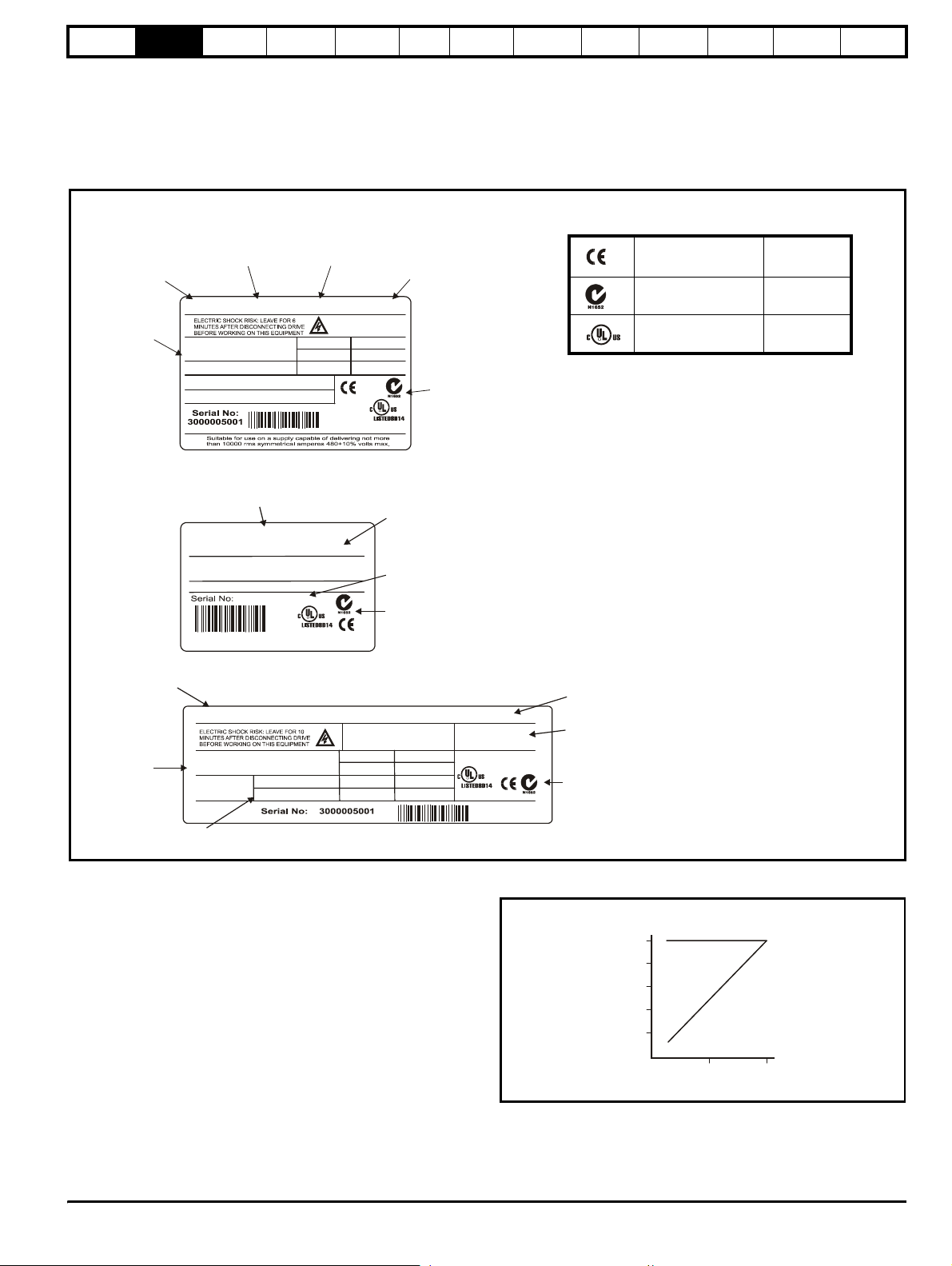
2.3 Nameplate description - drive
identification
The drive label is found on the top surface of the control pod (right
angles to the display) on Unidrive sizes 1 to 3 and size 5 control module,
and on the side of the Unidrive size 4 and size 5 power module.
Figure 2-1 Typical drive rating labels
Optimisation Macros
Advanced
Parameters
Technical
Data
Diagnostics
UL Listing
Information
Unidrive size 1 to 4 rating label
ve type
(STD,LV,
VTC, LFT)
Power rating
Model
UNI3401 VTC 15kW
Drive
ratings
VOLTAGE 50/60 Hz 3Ph
CURRENT (A)
OVERLOAD: 40.8A FOR 60 SECS
SOFTWARE VERSION: 03.02.11
Unidrive size 5 control module rating label
UNIDRIVE SIZE 5
CONTROL MODULE HW2
IT IS ESSENTIAL TO READ
THE MANUAL BEFORE
CONNECTING THE DRIVE.
SOFTWARE VERSION: 03.02.11
3000005001
INPUT OUTPUT
380/480V 380/480V
27A 34.0A
TO BE USED IN CONJUNCTION
WITH UNIDRIVE SIZE 5 HW2
POWER MODULES (S)
STDL01
IND.
R
CONT..
EQ.
MADE IN THE U.K.
STDJ41
IT IS ESSENTIAL TO READ
THE MANUAL BEFORE
CONNECTING THE DRIVE.
IND.
CONT..
EQ.
MADE IN THE U.K.
Customer and
date code
R
Hardware
revision
Customer and
date code
Approvals
Approval
Key to Approvals
CE approval Europe
C Tick approval Australia
UL / cUL approval
R
USA &
Canada
Unidrive size 5 power module rating label
Drive
ratings
UNI5401 POWER MODULE HW2 110V FAN FITTED
VOLTAGE 50/60 Hz 3Ph
CURRENT (A)
Dual current
ratin
OVERLOAD: 150 FOR 60 SECS
OVERLOAD: 120 FOR 60 SECS
IT IS ESSENTIAL TO READ
THE MANUAL BEFORE
CONNECTING THE DRIVE.
INPUT OUTPUT
380/480V 380/480V
220.0A 240.0A
280.0A 300.0A
2.4 Model variants
2.4.1 Unidrive standard industrial (STD)
...for constant torque loads (All frame sizes)
Operating modes:
Open Loop
Closed Loop vector
Servo
Regen
Overload:
Open loop 150% for 60s
Closed loop vector 175% for 60s (sizes 1 to 4), 150%* for 60s (size
5)
Servo 175% for 4s (sizes 1 to 4), 150%* for 4s (size 5)
Regen 150% for 60s
* Multiples of 300A output current with 120% overload or multiples of
240A with 150% overload
Customer and
STDL01
HEATSINK FAN
110V/120V 50/60HZ
IND.
CONT..
R
EQ.
MADE IN
THE U.K.
date code
Heatsink fan
ratings
Approvals
Figure 2-2 Constant torque load
Percent kW
and torque
100
80
60
40
20
0
Torque
50 10
Percent s
kW
eed
Unidrive User Guide 9
Issue Number: 9 www.controltechniques.com
Page 10

Safety
060
0
0
P
p
Information
Product
Information
Mechanical
Installation
Electrical
Installation
Getting
Star ted
Menu 0
Running
the motor
Optimisation Macros
Advanced
Parameters
Technical
Data
Diagnostics
UL Listing
Information
2.4.2 Unidrive LFT
...for lift applications
Overloads and operating modes as Unidrive standard industrial, in
addition:
low acoustic noise
9kHz default switching frequency
S4/S5 duty cycle only
Figure 2-3 Standard S4/S5 duty cycle (Unidrive LFT)
150%
100%
Frequency / speed
0
Current
0
2
50Hz
RPM
1500
2
2.4.3 Unidrive VTC
...for quadratic load (variable torque) applications (fans and pumps)
Open loop fixed boost mode only
120% overload for 60s
Figure 2-4 Variable torque mode
ercent kW
and torque
100
80
60
40
20
0
Torque
50 10
Percent s
kW
eed
2.4.4 Unidrive REGEN
All sizes of Unidrive can be used in regen mode. However, Unidrive
sizes 3 and 4 require an internal modification before being used in a
regen system.
This modification is already completed if the drive has been ordered as a
Unidrive REGEN.
2.5 Operating modes
All variants of Unidrive (except VTC) are designed to operate in any of
the following modes:
1. Open loop mode
V/f mode (V/ Hz)
Open loop vector
2. Closed loop vector
3. Servo
4. Regen
Unidrive VTC can only operate in open loop quadratic V/f mode.
2.5.1 Open Loop mode (OL)
For use with standard AC induction motors.
The drive applies power to the motor at frequencies varied by the user.
The motor speed is a result of the output frequency of the drive and slip
due to the mechanical load. The drive can improve the performance of
the motor by applying slip compensation. The performance at low speed
depends on whether V/f mode or open loop vector mode is selected.
V/f mode
The voltage applied to the motor is directly proportional to the frequency
except at low speed where a voltage boost is provided which is set by
the user. This mode should used for multi-motor applications.
Typically 100% torque at 4Hz.
Open loop vector mode
The voltage applied to the motor is directly proportional to the frequency
except at low speed where the drive uses motor parameters to apply the
correct voltage to keep the flux constant under varying load conditions.
Typically 100% torque at 1Hz.
2.5.2 Closed loop vector mode (VT)
For use with induction motors with a speed feedback device fitted.
The drive directly controls the speed of the motor using the feedback
device to ensure the rotor speed is exactly as demanded. Motor flux is
accurately controlled at all times to provide full torque all the way down
to zero speed.
Typically 175% torque at 0rpm.
2.5.3 Servo (SV)
For use with permanent magnet brushless motors with a speed and
position feedback device fitted.
The drive directly controls the speed of the motor using the feedback
device to ensure the rotor speed is exactly as demanded. Flux control is
not required because the motor is self excited by the permanent
magnets which form part of the rotor.
Absolute position information is required from the feedback device to
ensure the output voltage is accurately matched to the back EMF of the
motor.
Typically 175% torque at 0rpm
2.5.4 Regen
For use as a regenerative front end for four quadrant operation.
Regen operation allows bi-directional power flow to and from the AC
supply. This provides far greater efficiency levels in applications which
would otherwise dissipate large amounts of energy in the form of heat in
a braking resistor.
The harmonic content of the input current is negligible due to the
sinusoidal nature of the waveform when compared to a conventional
bridge rectifier or thyristor front end.
See the Regen Installation Guide for more information on this operating
mode.
2.5.5 Key to operating mode abbreviations
Abbreviations are throughout this User Guide to define the operating
mode for which the information applies as follows:
OL> Open loop
CL> Closed loop (which incorporates closed loop vector and
servo mode)
VT> Closed loop vector mode
SV> Servo
10 Unidrive User Guide
www.controltechniques.com Issue Number: 9
Page 11
Safety
A
Information
Product
Information
Mechanical
Installation
Electrical
Installation
Getting
Star ted
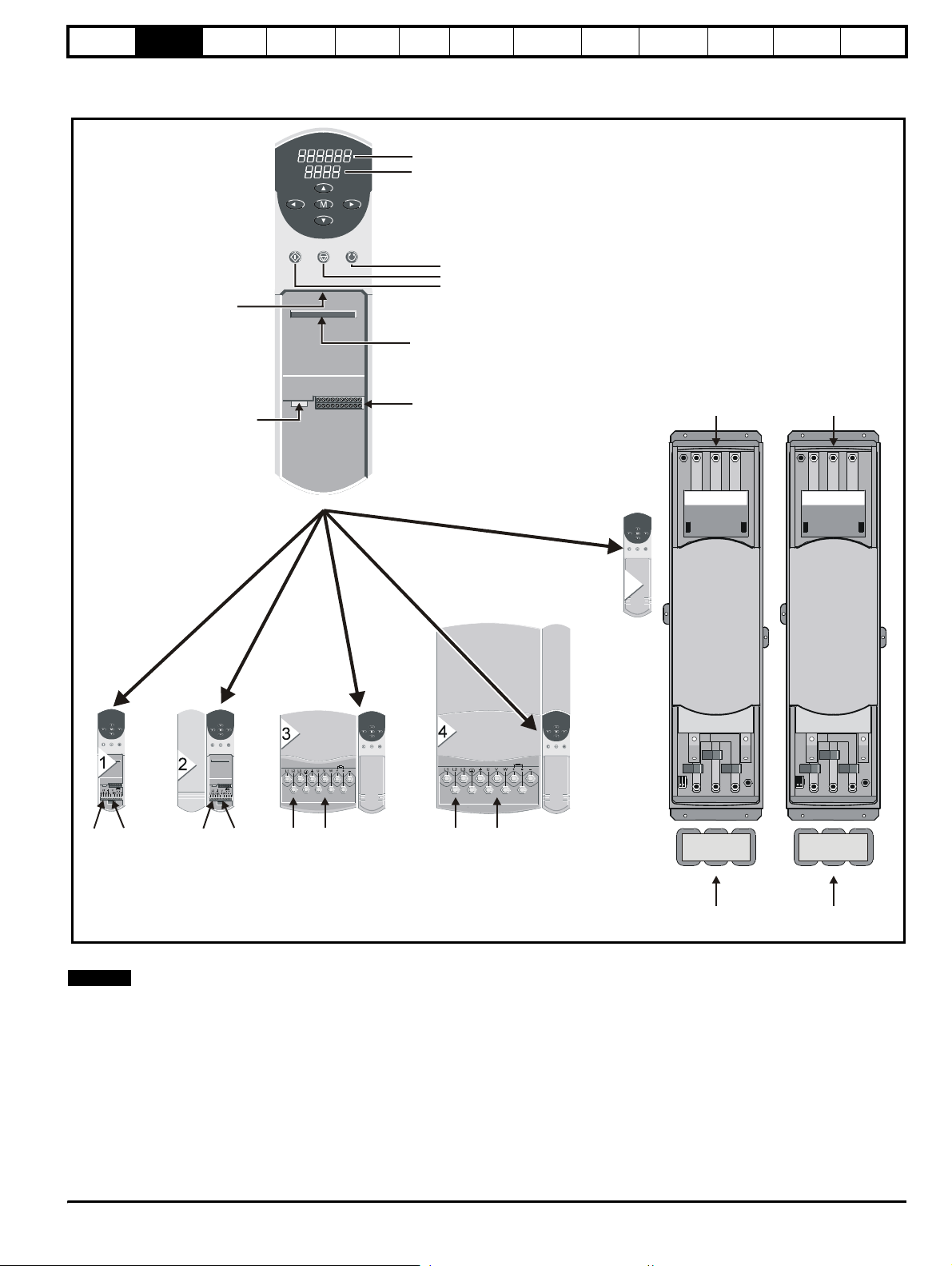
2.6 Drive features
Figure 2-5 Features of the drive (Size 1 to 5)
Menu 0
Running
the motor
Upper display
Lower display
Optimisation Macros
Advanced
Parameters
Technical
Data
Diagnostics
UL Listing
Information
Programming keys
Large option
module connection
Encoder connection
{
Control keys
Forward / Reverse
Stop / Reset
Run
Small option
module connection
Control connectors
AC
In
AC
In
5
NOTE
CInAC
Out
ACInAC
Out
N
ACInAC
Out
ACInAC
Out
Sharing
choke
AC
Out
Sharing
choke
AC
Out
Unidrive size 5 consists of a control module and one or more power
modules.
For power ratings greater than 160kW / 200hp, multiple power modules
(up to a maximum of 8) can be connected in parallel.
When multiple power modules are used, an output sharing choke is
required before the drive outputs are connected together.
Unidrive User Guide 11
Issue Number: 9 www.controltechniques.com
Page 12
Safety
us
et
Information
Product
Information
Mechanical
Installation
Electrical
Installation
Getting
Star ted
Menu 0
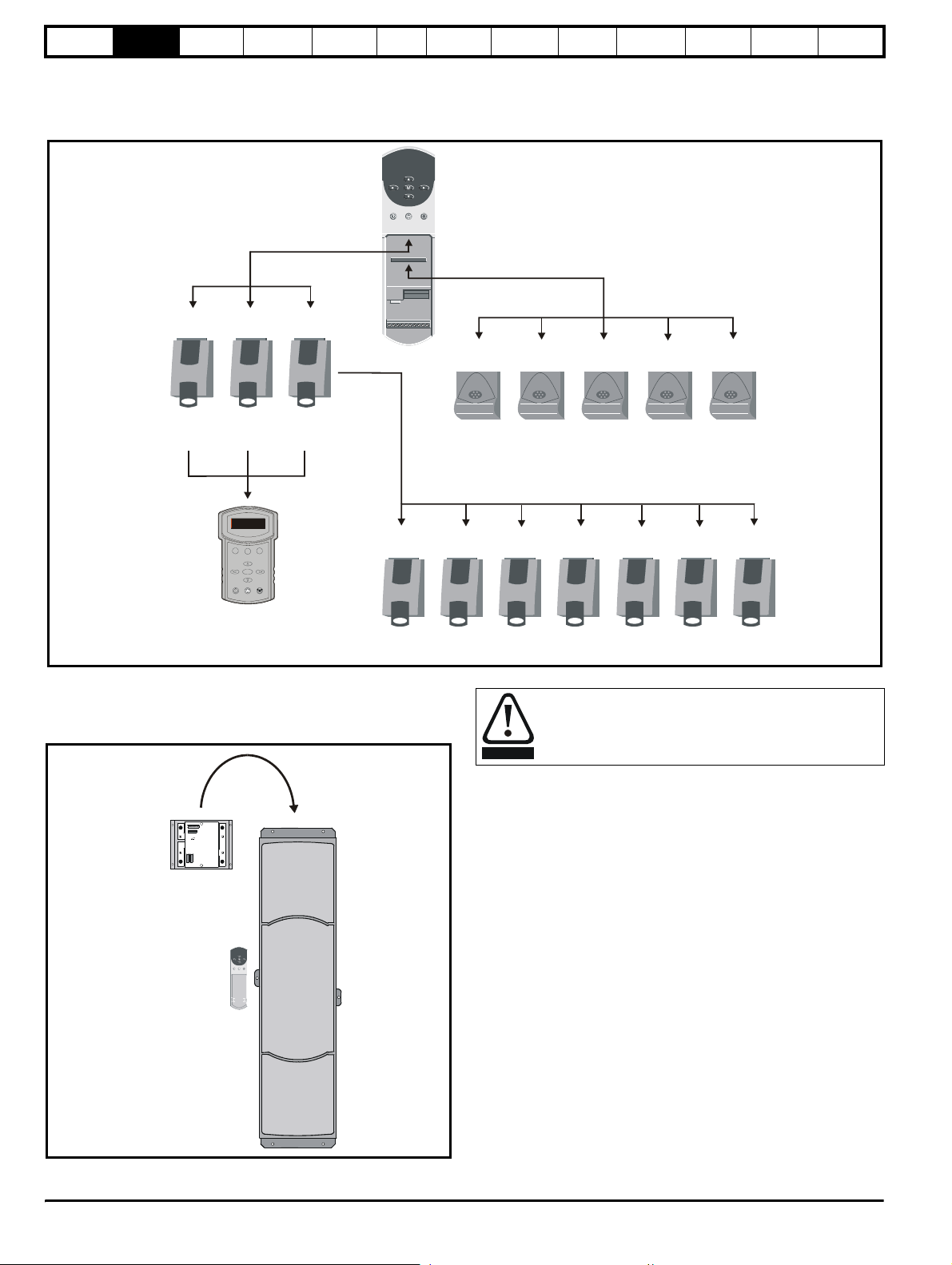
2.7 Option Modules
The following option modules are available for use with Unidrive.
Figure 2-6 Unidrive options available for all sizes
Running
the motor
Optimisation Macros
Advanced
Parameters
Technical
Data
Diagnostics
UL Listing
Information
Applications
Applications
F3
UD70
module
module
UD73 UD74 UD75
Profibus-DP Interbus CT Net Modbus
UD78 UD71
Servo RS232
RS485
9901 11
destination addr
F1
F2
M
Universal
Keypad
Unidrive sizes 1 to 4 have built in braking transistors; for Unidrive size 5
a braking option can be fitted if required as shown below:
Figure 2-7 Braking option available for Size 5
UD55 UD53 UD52 UD51 UD50
Cloning
module
Resolver Sin Cos
Encoder
UD76
Pl
Second
Encoder
UD77 UD77
Device
N
CAN CANopen
Extra I/O
The drive must be powered down for a minimum duration of
10 minutes before an option module is fitted or removed.
WARNING
UD77
2.8 More information
The following manuals are also available providing full information on the
various option modules, regen mode and advanced product use:
• Unidrive Advanced User Guide
• Regen Installation Guide
Size 5 Braking
option
• UD50 User Guide (Additional I/O small option module)
• UD51 User Guide (Second encoder small option module)
• UD52 User Guide (SINCOS encoder interface small option module)
• UD53 User Guide (Resolver interface small option module)
• UD55 User Guide (Cloning interface small option module)
• UD70 User Guide (Large option module and software)
• UD71 User Guide (Serial communications large option module)
• UD73 User Guide (Profibus-DP large option module)
• UD74 User Guide (Interbus large option module)
• UD75 CT Net User Guide (Large option module)
• UD76 User Guide (Modbus Plus large option module)
• UD77 User Guide (Device Net large option module)
• UD78 User Guide (Servo large option module)
• CAN User Guide (Large option module)
• CANopen User Guide (Large option module)
• Universal Keypad User Guide
• Universal Keypad Advanced User Guide
Please also see the Unisoft drive commissioning software which
contains a help file detailing full advanced parameter descriptions and
other useful information.
12 Unidrive User Guide
www.controltechniques.com Issue Number: 9
Page 13

Safety
Information
Product
Information
Mechanical
Installation
Electrical
Installation
Getting
Star ted
Menu 0
Running
the motor
Optimisation Macros
Advanced
Parameters
Technical
Data
Diagnostics
Information
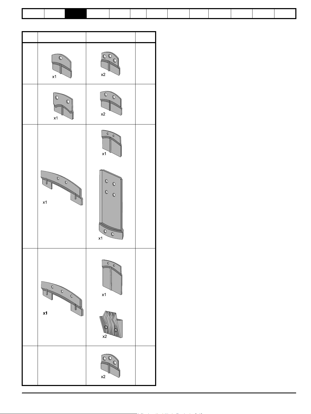
2.9 Items supplied with the drive
Size 1 Size 2 Size 3 Size 4 Size 5 control Size 5 power
Certificate of quality Certificate of quality Certificate of quality Certificate of quality Certificate of quality Certificate of quality
Safety Booklet Safety Booklet Safety Booklet Safety Booklet Safety Booklet
Mounting brackets Mounting brackets Mounting brackets Mounting brackets Mounting brackets
Interface leads
UL Listing
Control connectors Control connectors Control connectors Control connectors Control connectors
345678910
12
21 22 23 24 25 26 27 28 29 30 3121 22 23 24 25 26 27 28 29 30 31
11
345678910
12
21 22 23 24 25 26 27 28 29 30 3121 22 23 24 25 26 27 28 29 30 31
11
345678910
12
21 22 23 24 25 26 27 28 29 30 3121 22 23 24 25 26 27 28 29 30 31
11
345678910
12
21 22 23 24 25 26 27 28 29 30 3121 22 23 24 25 26 27 28 29 30 31
11
345678910
12
21 22 23 24 25 26 27 28 29 30 3121 22 23 24 25 26 27 28 29 30 31
Gasket foam Gasket foam Gasket foam Gasket foam UL Warning label
CAUTION
Risk of Electric Shock
Power down unit 10minutes
before removing cover
-
.
+
Power connector
UL Warning label UL Warning label
CAUTION
Risk of Electric Shock
Power down unit 10minutes
before removing cover
CAUTION
Risk of Electric Shock
Power down unit 10minutes
before removing cover
Power connector
L3
L1 L2
U
VW
UL Warning label UL Warning label
CAUTION
Risk of Electric Shock
Power down unit 10minutes
before removing cover
CAUTION
Risk of Electric Shock
Power down unit 10minutes
before removing cover
11
Unidrive User Guide 13
Issue Number: 9 www.controltechniques.com
Page 14
Safety
Information
Product
Information
Mechanical
Installation
Electrical
Installation
Getting
Star ted
Menu 0
Running
the motor
3 Mechanical Installation
This chapter describes how to use all mechanical features to install the
drive. Key features of this chapter include:
• Option module fitting
• Mounting methods
• Enclosure sizing and layout
• Terminal location and torque settings
3.1 Safety information
Follow the instructions
The mechanical and electrical installation instructions must
be adhered to. Any questions or doubt should be referred to
WARNING
WARNING
3.2 Planning the installation
The following considerations must be made when planning the
installation:
3.2.1 Access
Access must be restricted to authorised personnel only. Safety
regulations which apply at the place of use must be complied with.
3.2.2 Environmental protection
The drive must be protected from:
• moisture, including dripping water or spraying water and
• contamination with electrically conductive material
• contamination with any form of dust which may restrict the fan, or
• temperature beyond the specified operating and storage ranges
3.2.3 Cooling
The heat produced by the drive must be removed without its specified
operating temperature being exceeded. Note that a sealed enclosure
gives much reduced cooling compared with a ventilated one, and may
need to be larger and/or use internal air circulating fans.
For further information, please refer to section 3.7.2 Enclosure sizing on
page 24.
3.2.4 Electrical safety
The installation must be safe under normal and fault conditions.
Electrical installation instructions are given in Chapter 4 Electrical
Installation on page 37.
the supplier of the equipment. It is the responsibility of the
owner or user to ensure that the installation of the drive and
any external option unit, and the way in which they are
operated and maintained, comply with the requirements of
the Health and Safety at Work Act in the United Kingdom or
applicable legislation and regulations and codes of practice in
the country in which the equipment is used.
Competence of the installer
The drive must be installed by professional assemblers who
are familiar with the requirements for safety and EMC. The
assembler is responsible for ensuring that the end product or
system complies with all the relevant laws in the country
where it is to be used.
condensation. An anti-condensation heater may be required, which
must be switched off when the drive is running.
impair airflow over various components
Optimisation Macros
If it is necessary to meet strict emission limits, or if it is known that
electromagnetically sensitive equipment is located nearby, then full
precautions must be observed. These will include the use of RFI filters at
the drive inputs, which must be located very close to the drives. Space
must be made available for the filters and allowance made for carefully
segregated wiring. Both levels of precautions are covered in section
4.8 EMC (Electromagnetic compatibility) on page 44.
Advanced
Parameters
Technical
Data
Diagnostics
UL Listing
Information
3.2.7 Hazardous areas
The drive must not be located in a classified hazardous areas unless it is
installed in an approved enclosure and the installation is certified.
3.3 Terminal cover removal
Isolation device
The AC supply must be disconnected from the drive using an
approved isolation device before any cover is removed from
WARNING
WARNING
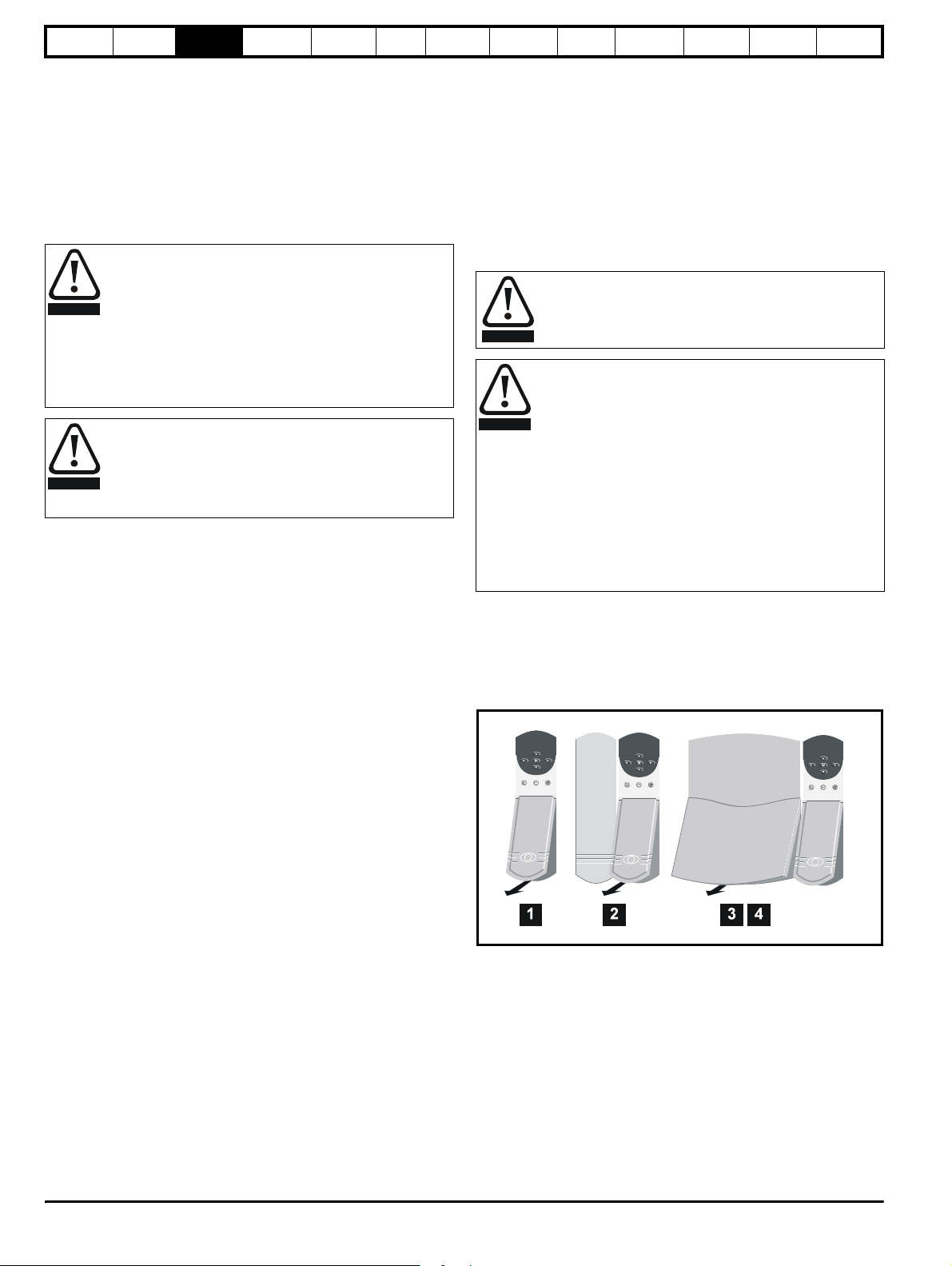
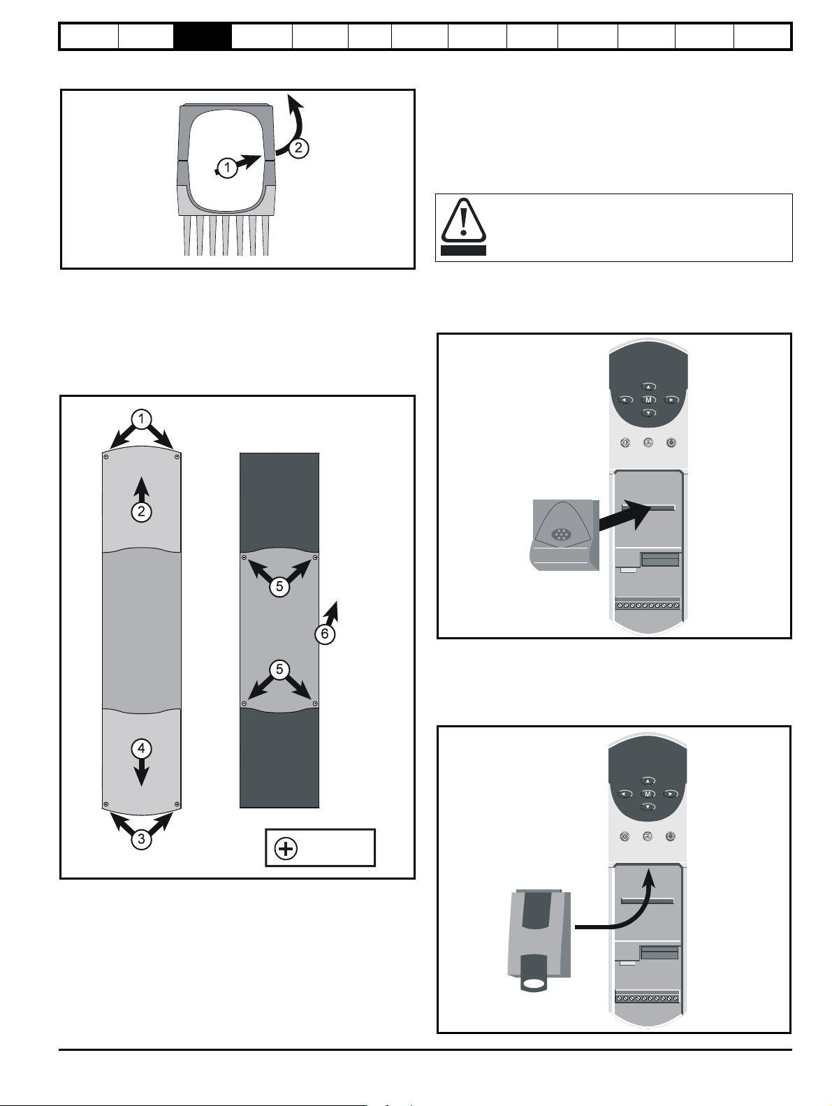
3.3.1 Removing the terminal covers
Unidrive sizes 1 to 4 and the size 5 control module are fitted with one or
two terminal covers depending on the model size. When model sizes 1,
3 and 4 are through-panel mounted, the terminal cover(s) must first be
removed in order for access to be gained to the lower mounting holes.
Figure 3-1 Removing the terminal covers
The terminal cover(s) of all models must be removed for access to the
electrical connectors.
the drive or before any servicing work is performed.
Stored charge
The drive contains capacitors that remain charged to a
potentially lethal voltage after the AC supply has been
disconnected. If the drive has been energised, the AC
supply must be isolated at least ten minutes before work
may continue.
Normally, the capacitors are discharged by an internal
resistor. Under certain, unusual fault conditions, it is possible
that the capacitors may fail to discharge, or be prevented
from being discharged by a voltage applied to the output
terminals. If the drive has failed in a manner that causes the
display to go blank immediately, it is possible the capacitors
will not be discharged. In this case, consult Control
Techniques or their authorised distributor.
3.2.5 Fire protection
The drive enclosure is not classified as a fire enclosure. A separate fire
enclosure must be provided.
3.2.6 Electromagnetic compatibility
Variable speed drives are powerful electronic circuits which can cause
electromagnetic interference if not installed correctly with careful
attention to the layout of the wiring.
Some simple routine precautions can prevent disturbance to typical
industrial control equipment.
14 Unidrive User Guide
www.controltechniques.com Issue Number: 9
Page 15
Safety
Information
Product
Information
Mechanical
Installation
Electrical
Information
Getting
Star ted
Menu 0
Running
the motor
Figure 3-2 View from the underside showing how a terminal cover
is removed from the drive
Remove terminal covers, as follows:
1. Working on either side of the terminal cover, push the inner edge of
the cover firmly outward until it becomes unclipped.
2. Swing the side of the cover outward and upward until the remaining
clips become released.
3. Remove the gland plate
Figure 3-3 Removing the three terminal covers on the Size 5
power module
Optimisation Macros
Advanced
Parameters
Technical
Data
Diagnostics
UL Listing
Information
3.4 Ingress protection
Size 1 to 4:
Gland plate(s) not fitted: IP00
Gland plate(s) fitted; cable glands not fitted: IP10
Gland plate(s) fitted; cable-glands fitted: IP40, NEMA 1
Size 5 power and control modules: IP00
3.5 Option module fitting / removal
Power down the drive before fitting / removing an option
module. Failure to do so may result in damage to the product.
CAUTION
The small option module should be placed under the two green securing
clips in the main housing beneath the drive display and pushed firmly
into place. Ensure the two connectors mate securely.
Figure 3-4 Fitting of a Unidrive small option module
The large option module slides into the space directly beneath the drive
display so that only the front face of the module can be seen. Ensure the
module clicks into place indicating that the two connectors have mated
successfully.
Figure 3-5 Fitting of a Unidrive large option module
M5 pozidriv
screw
Remove the three terminal covers on the power module, as follows:
1. Remove the two pozidriv screws.
2. Remove the upper cover.
3. Remove the two pozidriv screws.
4. Remove the lower cover until it is released from the middle cover.
5. Remove the four screws that are now revealed.
6. Remove the middle cover.
All the power terminals and ribbon-cable connectors are now accessible.
Unidrive User Guide 15
Issue Number: 9 www.controltechniques.com
Page 16
Safety
n
Information
Product
Information
Mechanical
Installation
Electrical
Installation
Getting
Star ted
Menu 0
Running
the motor
Optimisation Macros
Advanced
Parameters
Technical
Data
Diagnostics
UL Listing
Information
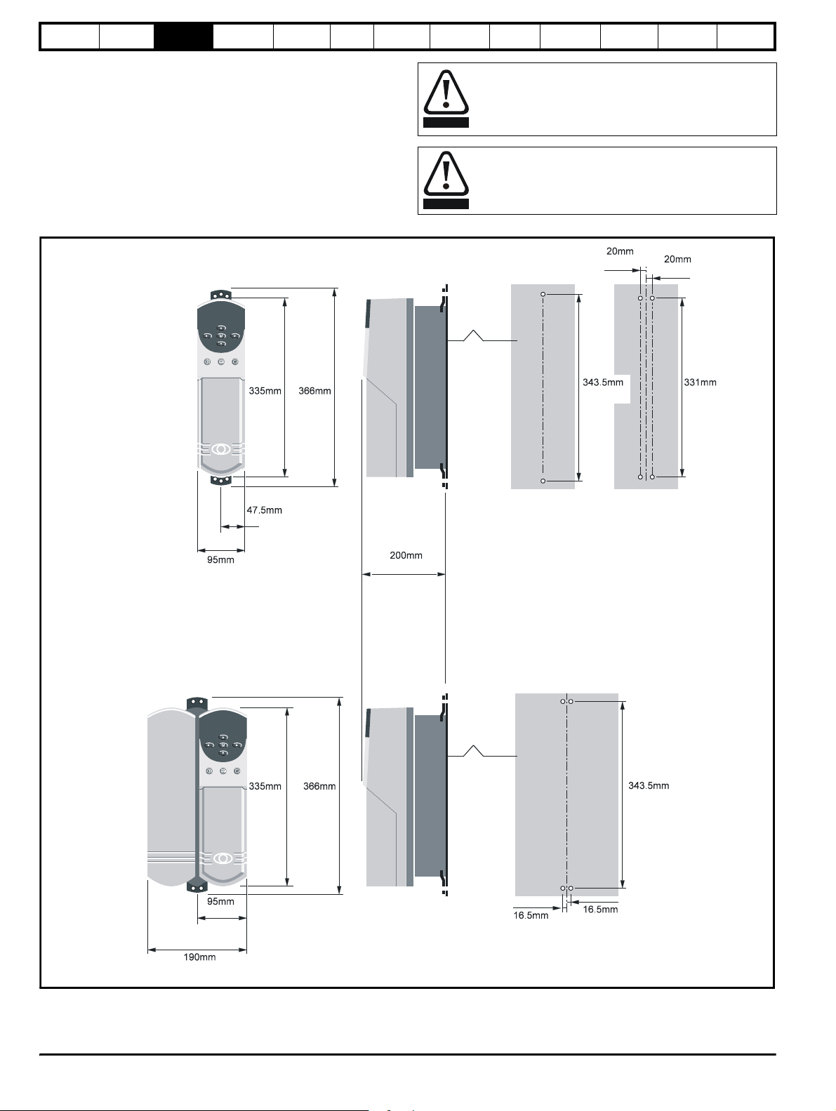
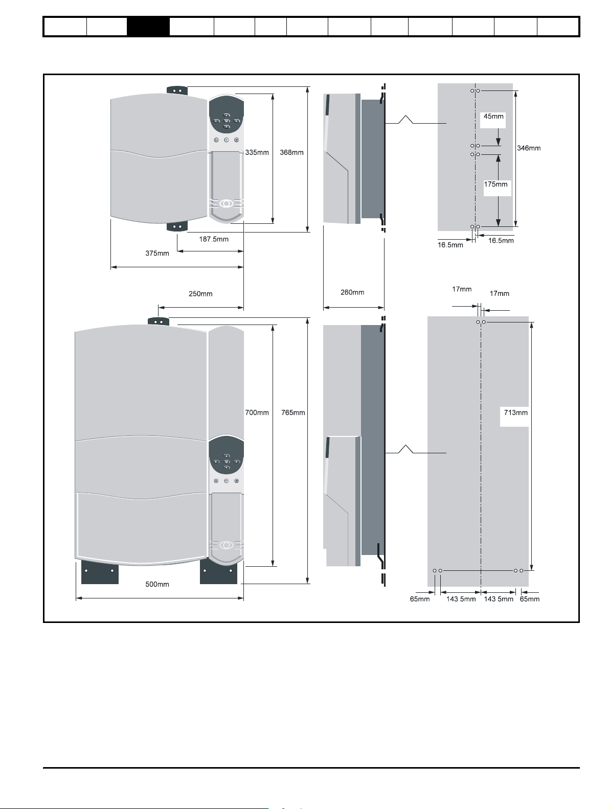
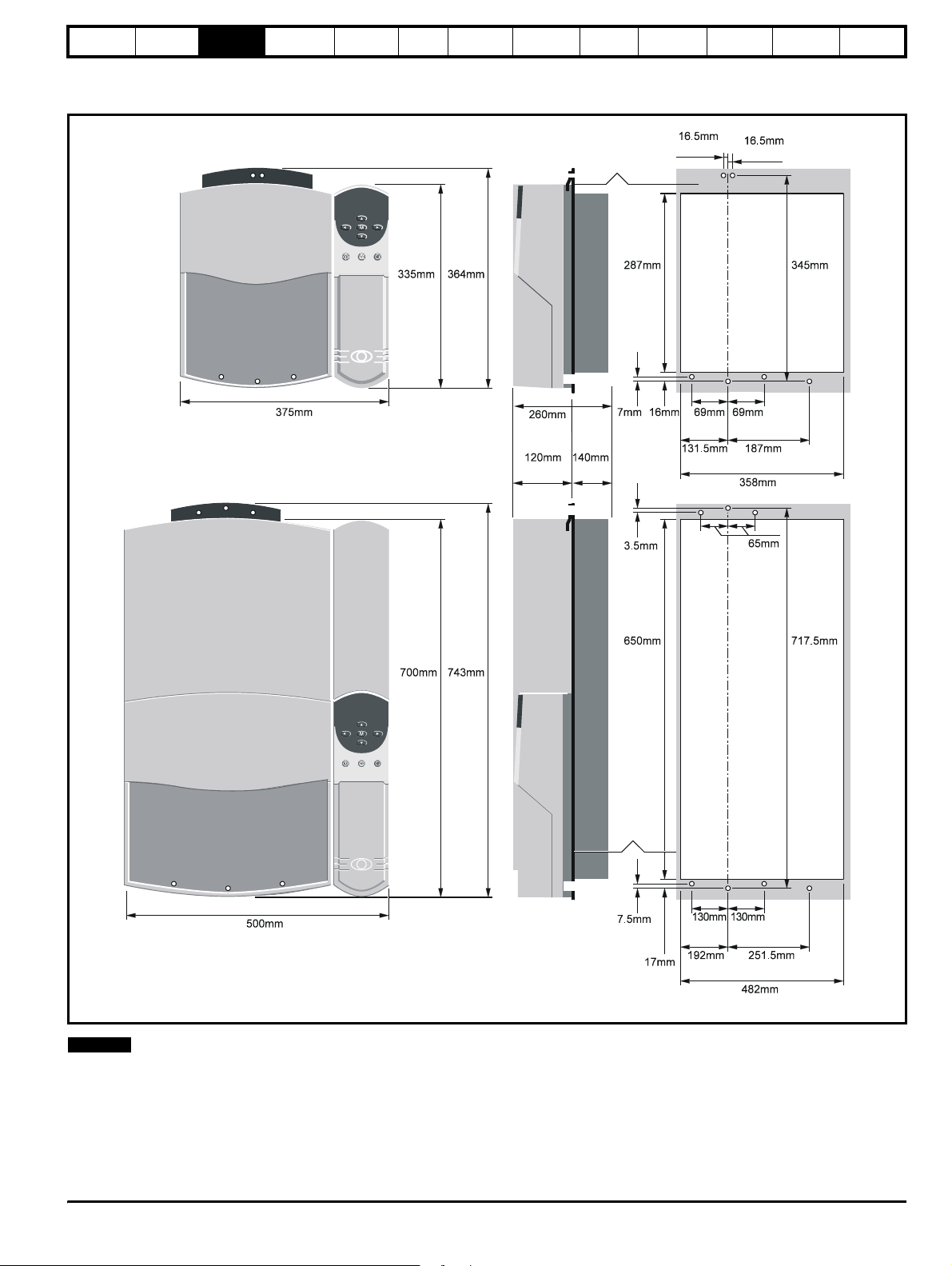
3.6 Mounting methods
Unidrive sizes 1 to 4 can be either through hole or surface mounted
using the appropriate brackets.
The Unidrive size 5 consists of two modules:
• the control module should be surface mounted
• the power module must be through hole mounted.
The following drawings show the dimensions of the drive and mounting
holes for each method to allow a back plate to be prepared.
Figure 3-6 Surface mounting of model sizes 1 and 2
Model
size 1
13.189in 14.409in
WARNING
WARNING
Lifting the drive
The weights of model sizes 3 and 4 are 22kg (49lbs) and
70kg (154lbs) respectively; the size 5 power module exceeds
100kg (220lbs). Use appropriate safeguards when lifting
these models.
If the drive has been used at high load levels for a period of
time, the heatsink may be hot. Human contact with the
heatsink should be restricted.
0.787in
Back-plate
13.524in
0.787in
13.031i
Model
size 2
3.740in
3.740in
1.870in
13.189in 14.409in
7.874in
Back-plate
0.650in
13.524in
0.650in
7.480in
16 Unidrive User Guide
www.controltechniques.com Issue Number: 9
Page 17
Safety
n
Information
Product
Information
Mechanical
Installation
Electrical
Information
Getting
Star ted
Figure 3-7 Surface mounting of model sizes 3 and 4
Model
size 3
Menu 0
Running
the motor
Optimisation Macros
Advanced
Parameters
Back-plate
Technical
Data
1.772in
Diagnostics
UL Listing
Information
Model
size 4
14.764in
7.382in
9.843in
13.189in 14.488in
27.559in30.118
in
10.236in
Back-plate
0.650in
0.669in
13.622i
6.890in
0.650in
0.669in
28.071in
19.685in
2.559in 2.559in5.650in 5.650in
Unidrive User Guide 17
Issue Number: 9 www.controltechniques.com
Page 18
Safety
Back-pl
n
Information
Product
Information
Mechanical
Installation
Electrical
Installation
Getting
Star ted
Menu 0
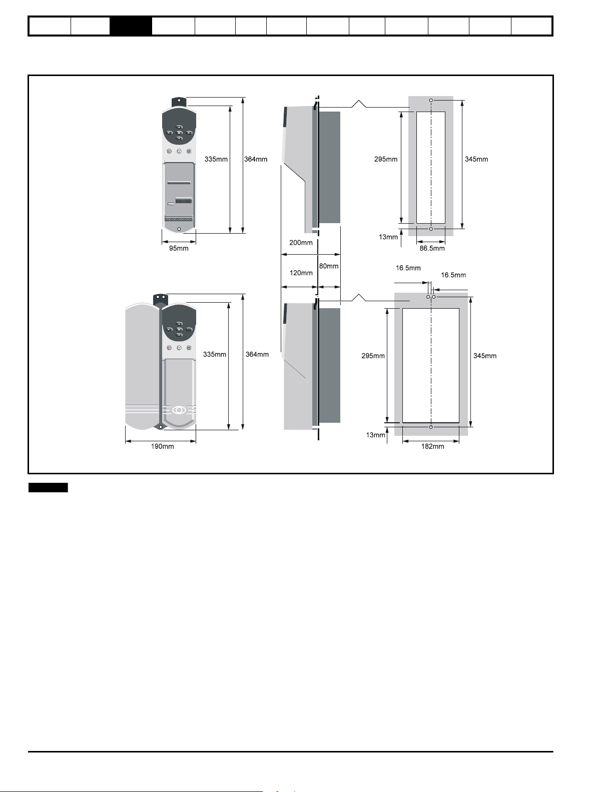
Figure 3-8 Through-panel mounting of model sizes 1 and 2
Model
size 1
Running
the motor
Optimisation Macros
ate
Advanced
Parameters
Technical
Data
Diagnostics
UL Listing
Information
Model
size 2
7.480in
3.740in
13.189in
13.189in
14.331in
14.331in
7.874in
4.724in
3.150
in
11.614in 13.583in
0.512in
3.406in
0.650in
Back-plate
11.614in 13.583i
0.512in
0.650in
7.165in
NOTE
N
When drives are through-panel mounted, a baffle plate is required to
ensure the correct level of air-flow is maintained through the heatsink.
For further information, please refer to section 3.9 Baffle plates on
page 28.
18 Unidrive User Guide
www.controltechniques.com Issue Number: 9
Page 19
Safety
8.9
Information
Product
Information
Mechanical
Installation
Electrical
Information
Getting
Star ted
Menu 0
Figure 3-9 Through-panel mounting of model sizes 3 and 4
Running
the motor
Optimisation Macros
Advanced
Parameters
Technical
Data
Diagnostics
UL Listing
Information
Model
size 3
Model
size 4
14.764in
13.189in 14.331in
10.236in
4.724in 5.512in
Back-plate
11. 299 in
0.276in0.630
0.138in 2.559in
0.650in
in
5.177in 7.362in
0.650in
13.583in
2.717in2.717in
14.094in
27.559in 29.252in
19.685in
NOTE
N
When drives are through-panel mounted, a baffle plate is required to
ensure the correct level of air-flow is maintained through the heatsink.
For further information, please refer to section 3.9 Baffle plates on
page 28.
25.591in 28.248in
Back-plate
0.295in
0.669in
5.118in 5.118in
7.559in 9.902in
1
72in
Unidrive User Guide 19
Issue Number: 9 www.controltechniques.com
Page 20
Safety
)
Information
Product
Information
Mechanical
Installation
Electrical
Installation
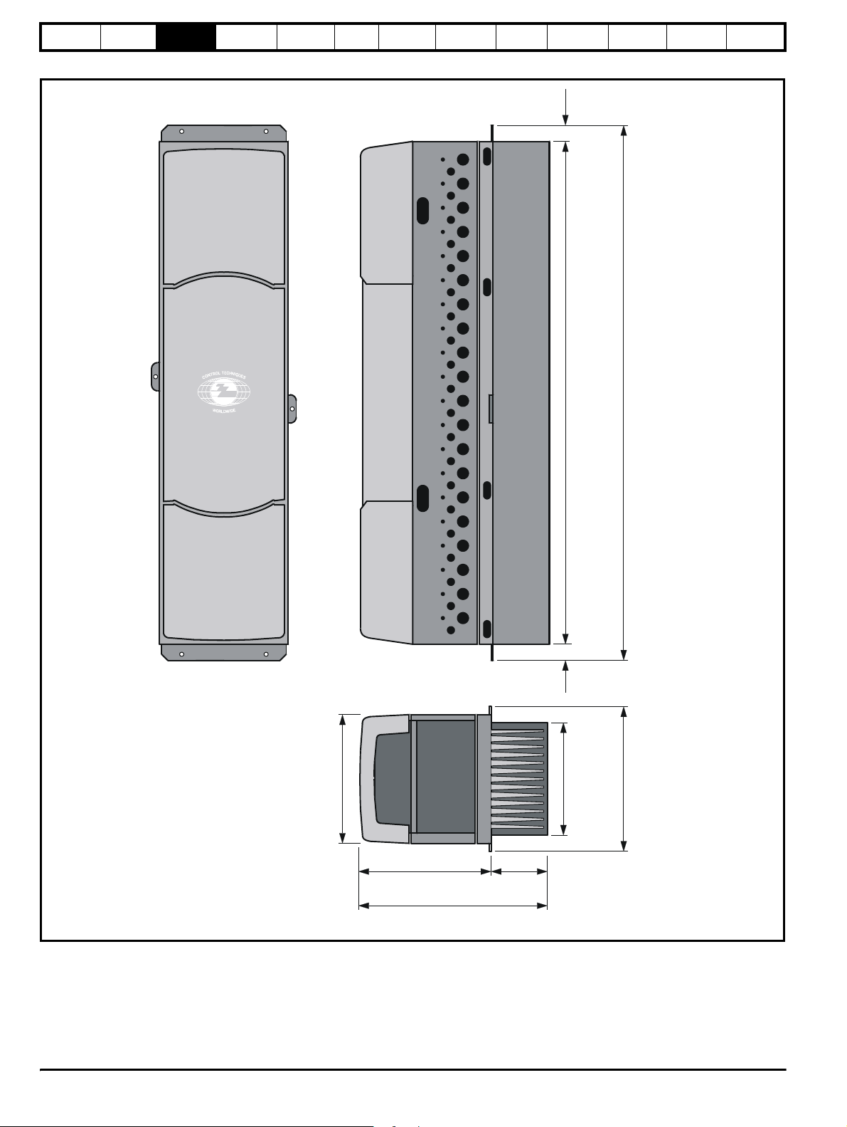
Figure 3-10 Unidrive Size 5 overall dimensions
Getting
Star ted
Menu 0
Running
the motor
Optimisation Macros
35.5mm
(1.398in)
Advanced
Parameters
Technical
Data
Diagnostics
UL Listing
Information
315mm
(12.402in)
1248mm
(49.134in)
35.5mm
(1.398in)
278mm
(10.945in)
1319mm
(51.926in)
355mm
(13.976in
340mm
(13.386in)
484mm
(19.055in)
144mm
(5.669in)
20 Unidrive User Guide
www.controltechniques.com Issue Number: 9
Page 21
Safety
(
Information
Product
Information
Mechanical
Installation
Electrical
Information
Getting
Star ted
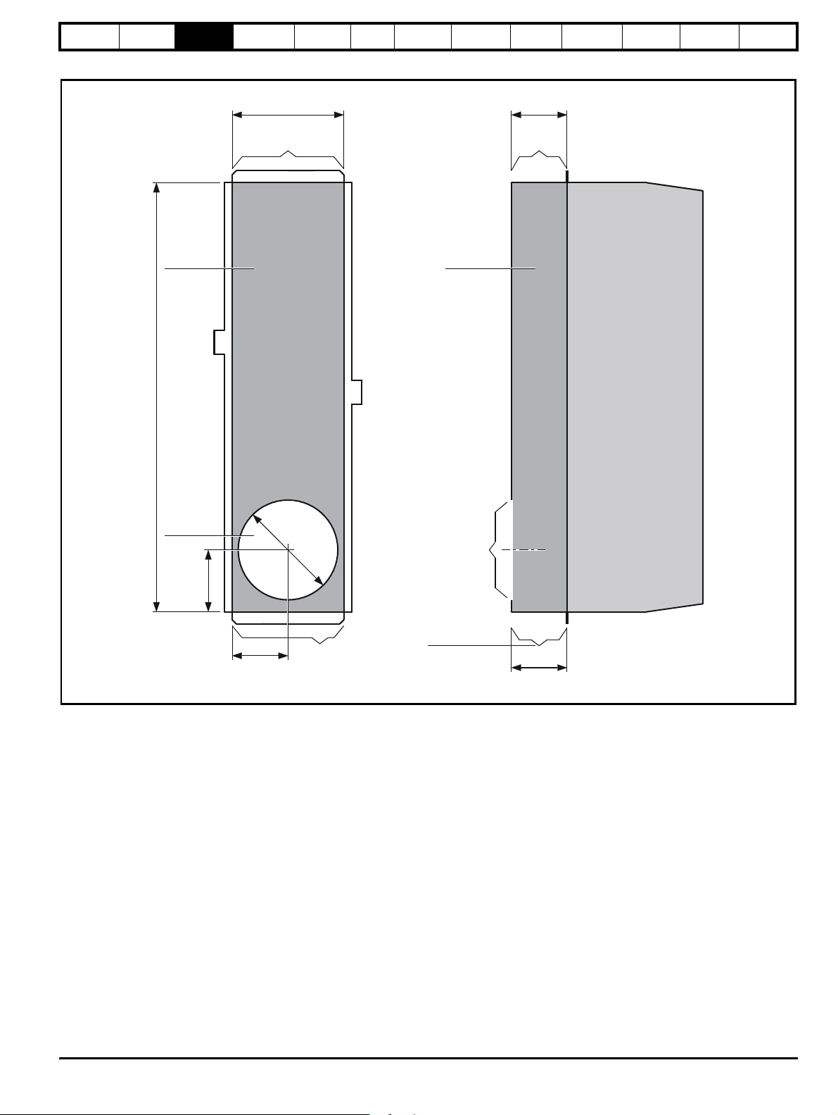
Figure 3-11 Unidrive Size 5 mounting dimensions
Menu 0
Running
the motor
Optimisation Macros
Advanced
Parameters
Technical
Data
Diagnostics
UL Listing
Information
Rear view of
power module
Heatsink
duct
1248mm
(49.134in)
278mm
(10.945in)
Exhaust port
Heatsink
duct
144mm
(5.669in)
Exhaust
port
Side view of
power module
Inlet port
(internal fan)
154mm
(6.063in)
139mm
(5.472in)
256mm
(10.079in)
Inlet port
(external fan)
Inlet port
(internal fan)
Alternative
inlet port
(external fan)
144mm
5.669in)
Unidrive User Guide 21
Issue Number: 9 www.controltechniques.com
Page 22
Safety
∅
0.433
m
20
Information
Product
Information
Mechanical
Installation
Electrical
Installation
Getting
Star ted
Menu 0
Running
the motor
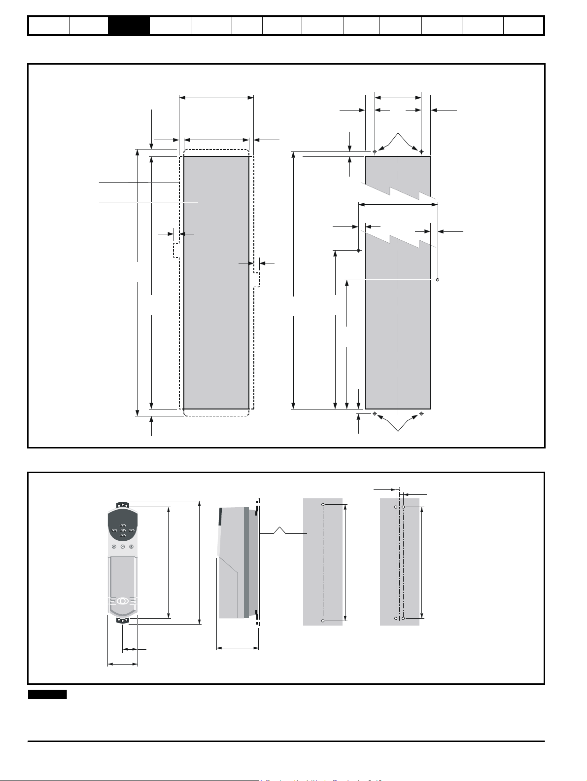
Figure 3-12 Unidrive size 5 backplate mounting holes and aperture
Optimisation Macros
Advanced
Parameters
Technical
Data
Diagnostics
UL Listing
Information
Outline of
the power
module
Aperture
Location of aperture in relation to
the outline of the power module
16.5mm
33.5mm
0.650in
1.319in
20mm
0.787in
1319mm
51.929in
1252mm
49.291in
315mm
12.402in
282mm
11.102in
16.5mm
0.650in
20mm
0.787in
1286mm
50.630in
Locations and dimensions of the
mounting holes in relation to the aperture
203mm
7.992in
∅
11m m
0.433in
339mm
13.346in
23.5mm
0.925in
28.5mm
1.122in
670mm
26.378in
37.5mm
1.476in
∅
8mm
0.315in
590mm
23.228in
37.5mm
1.476in
28.5m
1.122in
8mm
∅
0.315in
33.5mm
1.319in
Figure 3-13 Unidrive Size 5 control module surface mounting
Back-plate
NOTE
335mm
(13.189in)
47.5mm
(1.870in)
95mm
(3.740in)
N
368mm
(14.488in)
143mm
(5.630in)
The Unidrive size 5 control module should be located within 2m of the
power module to allow the interconnections to be made using the ribbon
cables supplied with the power module.
10mm
0.413in
(0.787in)
345mm
(13.583in)
mm
11m m
in
20mm
(0.787in)
332mm
(13.071in)
22 Unidrive User Guide
www.controltechniques.com Issue Number: 9
Page 23
Safety
Information
Product
Information
Mechanical
Installation
Electrical
Information
Getting
Star ted
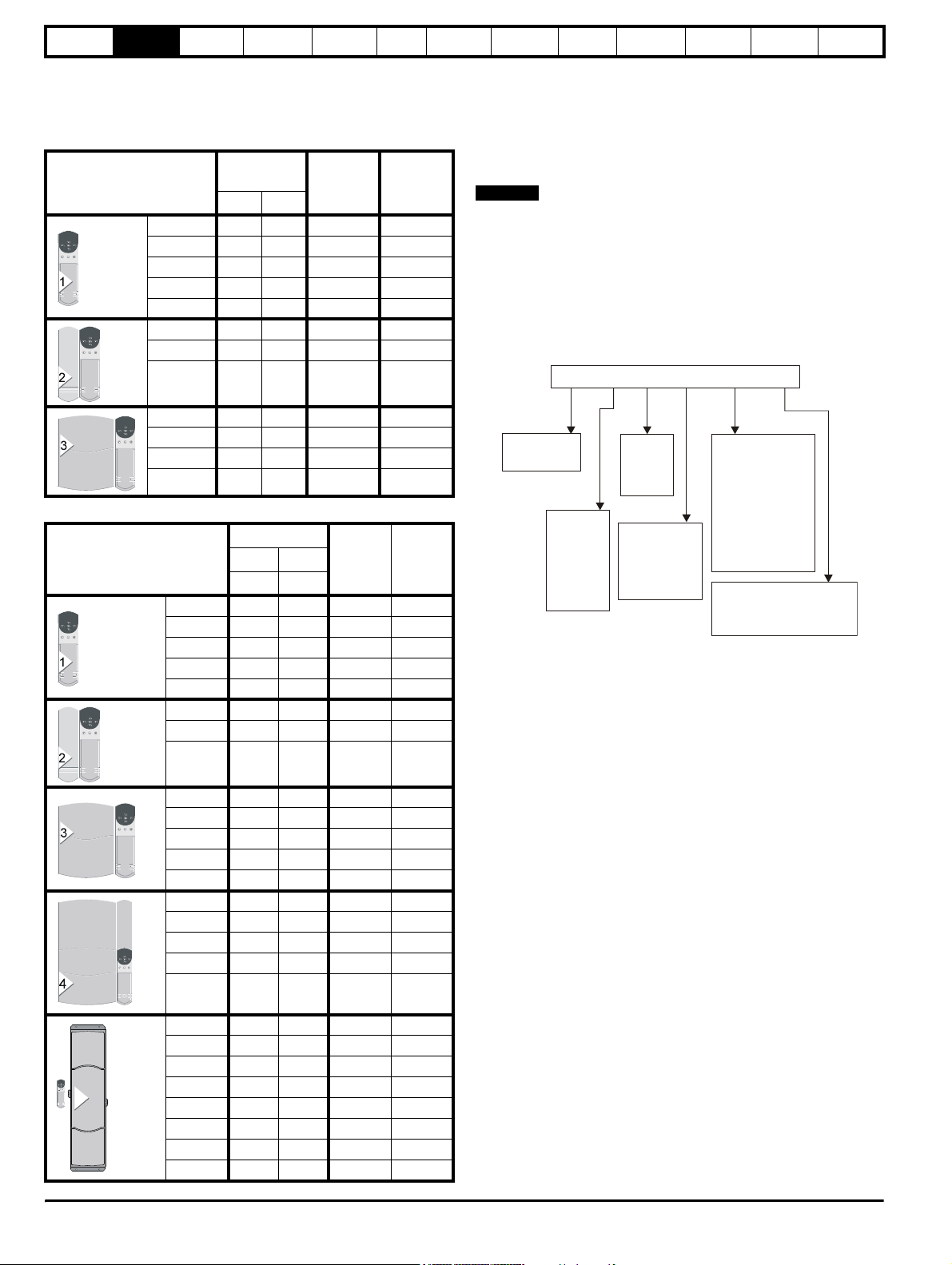
Table 3-1 General views of the mounting brackets
Menu 0
Running
the motor
Optimisation Macros
Advanced
Parameters
Technical
Data
Diagnostics
UL Listing
Information
Model
size
1
2
3
Through-panel Surface Hole size
M6
Upper and lower
M6
Upper and lower
Upper
M6
Lower
M6
(through-
panel)
4
Upper
M8
(surface)
Lower
5
M6
Upper and lower
Unidrive User Guide 23
Issue Number: 9 www.controltechniques.com
Page 24
Safety
m
Information
Product
Information
Mechanical
Installation
Electrical
Installation
Getting
Star ted
Menu 0
Running
the motor
3.7 Enclosure
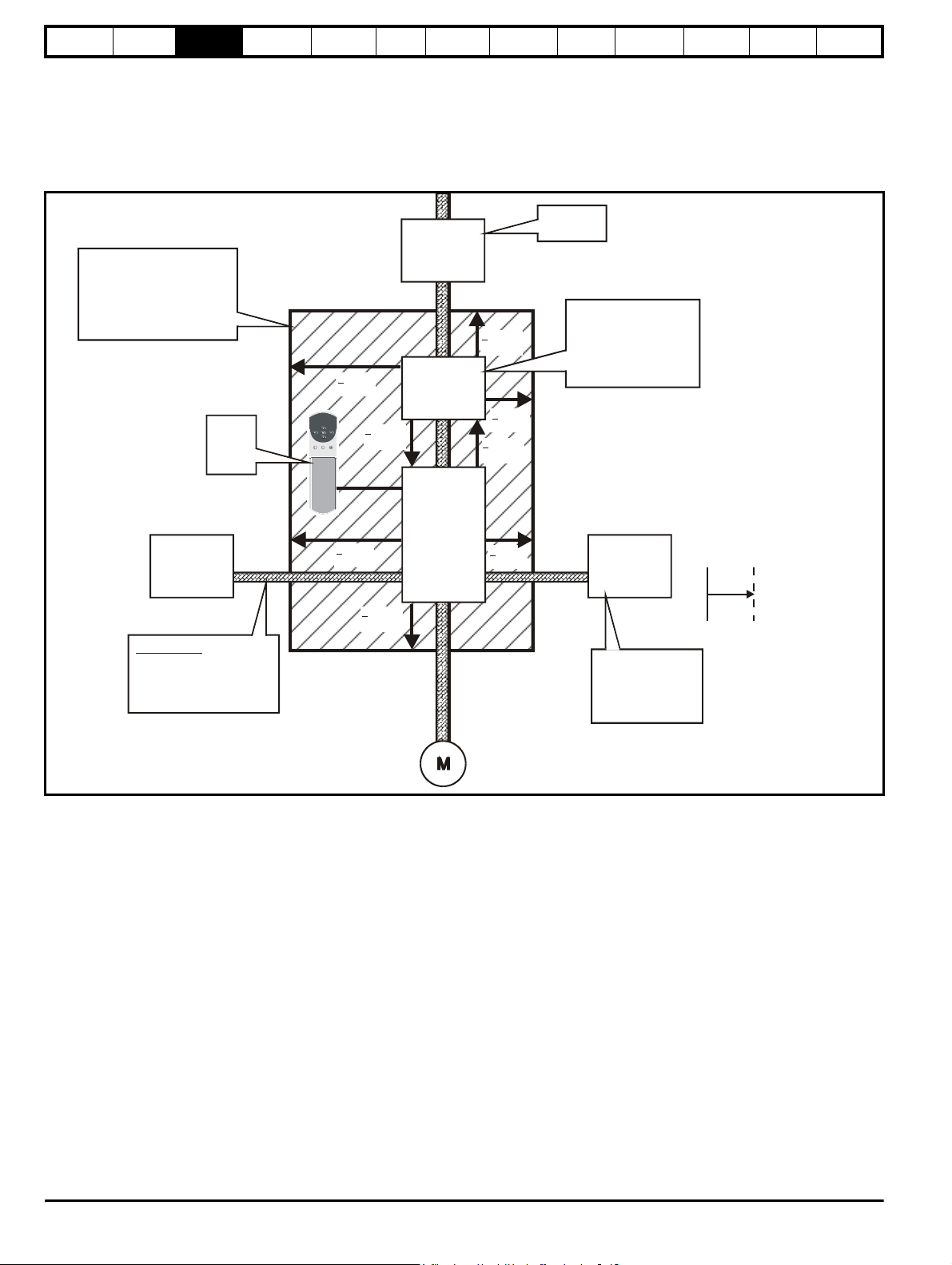
3.7.1 Enclosure Layout
Please observe the clearances in the diagram below taking into account
any appropriate notes for other devices / auxiliary equipment when
planning the installation.
Figure 3-14 Enclosure layout
AC supply
> 100mm
(3.937in)
contactor and
fuses or MCB
Optional
RFI filter
Ensure minimum clearances
are maintained for the
drive and RFI filter
Forced or convection air-flow
must not be restricted by any
object or cabling
Control
module
(size 5
only)
> 5mm
(0.197in)
Optimisation Macros
Locate
as required
> 100mm
(3.937in)
> 5mm
(0.197in)
> 100mm
(3.937in)
Advanced
Parameters
Locate as close to
the drive as possible
(to keep the cable
as short as possible)
respecting the minimum
clearances
Technical
Data
Diagnostics
Note: for EMC compliance
1) A separate RFI filter is
required for each drive
2) Power cabling must be
at least 100mm (4in) from
the drive in all directions
UL Listing
Information
Drive
> 5mm
Controller
Signal cables
Plan for all signal cables
to be routed at least
300mm (12in) from the drive
and any power cable
(0.197in)
> 100mm
(3.937in)
3.7.2 Enclosure sizing
1. Add the dissipation figures from section 11.1.2 Power dissipation (all
versions) on page 191 for each drive that is to be installed in the
enclosure.
2. If an RFI filter is to be used with each drive, add the dissipation
figures from section 11.2.1 Ratings on page 197 for each RFI filter
that is to be installed in the enclosure.
3. If the braking resistor is to be mounted inside the enclosure, add the
average power figures for each braking resistor that is to be installed
in the enclosure.
4. Calculate the total heat dissipation (in Watts) of any other equipment
to be installed in the enclosure.
5. Add the heat dissipation figures obtained above. This gives a figure
in Watts for the total heat that will be dissipated inside the enclosure.
Note: Footprint RFI filters
are available for Unidrive
> 5mm
(0.197in)
Optional
braking resistor
and overload
Locate resistor
external to cubicle
(preferably near to
or at the top of the
cubicle)
frame sizes 1 and 2
Indicates minimu
clearance required
from device
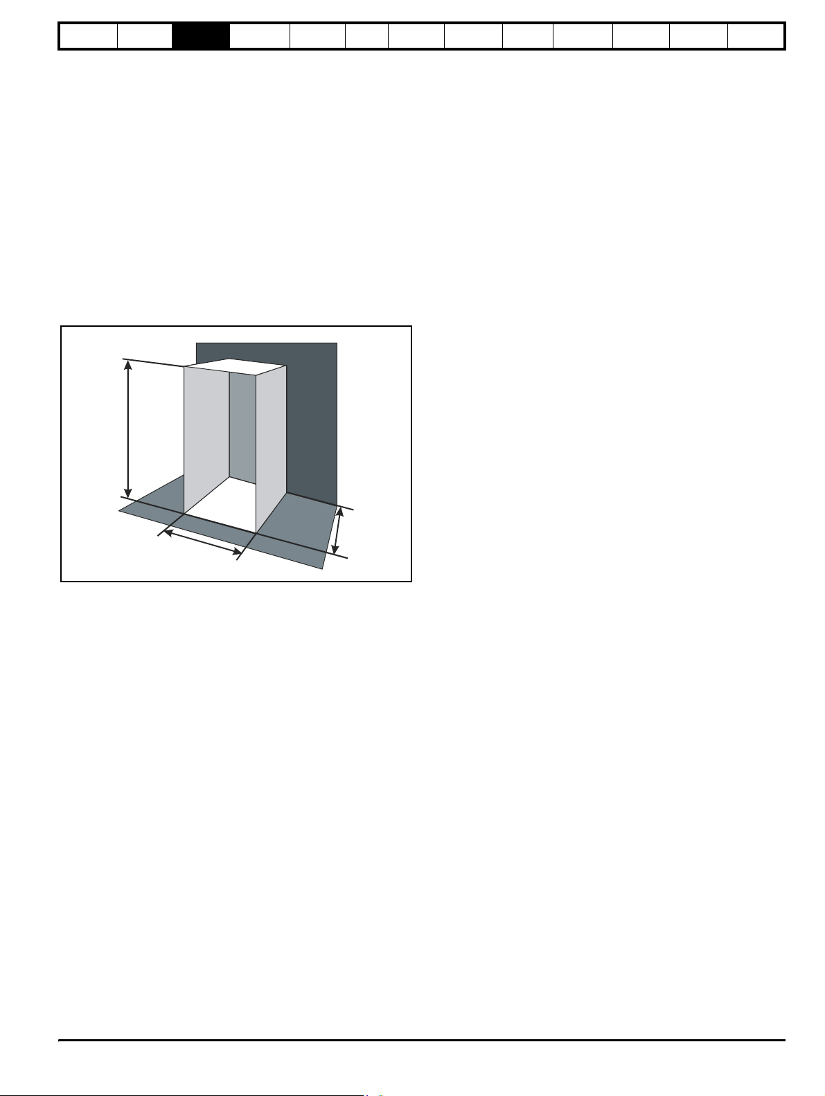
Calculating the size of a sealed enclosure
The enclosure transfers internally generated heat into the surrounding
air by natural convection (or external forced air flow); the greater the
surface area of the enclosure walls, the better is the dissipation
capability. Only the surfaces of the enclosure that are unobstructed (not
in contact with a wall or floor) can dissipate heat.
Calculate the minimum required unobstructed surface area A
enclosure from:
e
–()
kT
intText
P
-----------------------------------
A
=
Where:
A
Unobstructed surface area in m2 (1m2 = 10.8 ft2)
e
T
Maximum expected ambient temperature in
ext
enclosure
Maximum permissible ambient temperature in oC inside the
T
int
enclosure
P Power in Watts dissipated by all heat sources in the
enclosure
k Heat transmission coefficient of the enclosure material
2/o
in Wm
C
for the
e
o
C outside the
24 Unidrive User Guide
www.controltechniques.com Issue Number: 9
Page 25
Safety
Information
Product
Information
Mechanical
Installation
Electrical
Information
Getting
Star ted
Menu 0
Example
To calculate the size of an enclosure for the following:
• Two UNI1405 models
• Each drive to operate at 4.5kHz PWM switching frequency
• RFI filter for each drive
• Braking resistors are to be mounted outside the enclosure
• Maximum ambient temperature inside the enclosure: 40°C
• Maximum ambient temperature outside the enclosure: 30°C
Dissipation of each drive: 190W
Dissipation of each RFI filter: 7.7W (max)
Total dissipation: 2 x (190 + 7.7) = 395.4W
The enclosure is to be made from painted 2mm (0.079 in) sheet steel
having a heat transmission coefficient of 5.5W/m
2/o
C. Only the top, front,
and two sides of the enclosure are to be free to dissipate heat.
Figure 3-15 Enclosure having front, sides and top panels free to
dissipate heat
Running
the motor
Optimisation Macros
Advanced
Parameters
Technical
Data
Diagnostics
Calculating the air-flow in a ventilated enclosure
The dimensions of the enclosure are required only for accommodating
the equipment. The equipment is cooled by the forced air flow.
Calculate the minimum required volume of ventilating air from:
3kP
---------------------------
=
V
Where:
V Air-flow in m
T
ext
T
int
P Power in Watts dissipated by all heat sources in the
k Ratio of
Where:
Typically use a factor of 1.2 to 1.3, to allow also for pressure-drops in
dirty air-filters.
–
T
intText
3
per hour
Maximum expected ambient temperature in
enclosure
Maximum permissible ambient temperature in oC inside the
enclosure
enclosure
P
o
-------
P
l
P
is the air pressure at sea level
0
is the air pressure at the installation
P
I
UL Listing
Information
o
C outside the
H
D
W
Insert the following values:
T
40°C
int
30°C
T
ext
k 5.5
P 395.4W
The minimum required heat conducting area is then:
395.4
---------------------------------
A
=
e
5.5 40 30–()
2
=7.2m
(78ft2) (1m = 3.3 ft)
Estimate two of the enclosure dimensions - the height (H) and depth (D),
for instance. Calculate the width (W) from:
2HD–
A
e
--------------------------
=
W
HD+
Inserting H = 2m and D = 0.6m, obtain the minimum width:
7.2 2 2× 0.6×()–
----------------------------------------------
W
=
20.6+
= 1.8m (6ft)
If the enclosure is too large for the space available, it can be made
smaller only by attending to one or all of the following:
• Using a lower PWM switching frequency to reduce the dissipation in
the drives
• Reducing the ambient temperature outside the enclosure, and/or
applying forced-air cooling to the outside of the enclosure
• Reducing the number of drives in the enclosure
• Removing other heat-generating equipment
Example
To calculate the size of an enclosure for the following:
• Three UNI3401 models
• Each drive to operate at 6kHz PWM switching frequency
• RFI filter for each drive
• Braking resistors are to be mounted outside the enclosure
• Maximum ambient temperature inside the enclosure: 40
• Maximum ambient temperature outside the enclosure: 30
Dissipation of each drive: 670W
Dissipation of each RFI filter: 12.8W (max)
Total dissipation: 3 x (670 + 60) = 2048.4W
Insert the following values:
T
40°C
int
30°C
T
ext
k 1.3
P 2048.4W
Then:
31.3× 2048.4×
------------------------------------------
V
=
40 30–
3
/ hr (471ft3 / min)
3
/min)
(1m
= 799m
3
/ hr = 0.59ft
o
C
o
C
Unidrive User Guide 25
Issue Number: 9 www.controltechniques.com
Page 26
Safety
Information
Product
Information
Mechanical
Installation
Electrical
Installation
Getting
Star ted
Menu 0
Running
the motor
3.8 Ventilation
Unidrive sizes 1-4 are ventilated by internally supplied heatsink fans.
Ensure the minimum clearances around the drive are maintained to
allow air to flow freely.
The Unidrive size 5 requires ventilation at the front (control) and rear
(heatsink) of the module.
Two parallel independent paths must be provided as shown to ensure
the heat produced is dispersed.
A heatsink fan is fitted as standard on request however this requires
either a 110Vac or 240Vac external single phase power supply to be
connected at the bottom left hand corner of the power module.
The choice of fan power supply must be made when ordering the power
module.
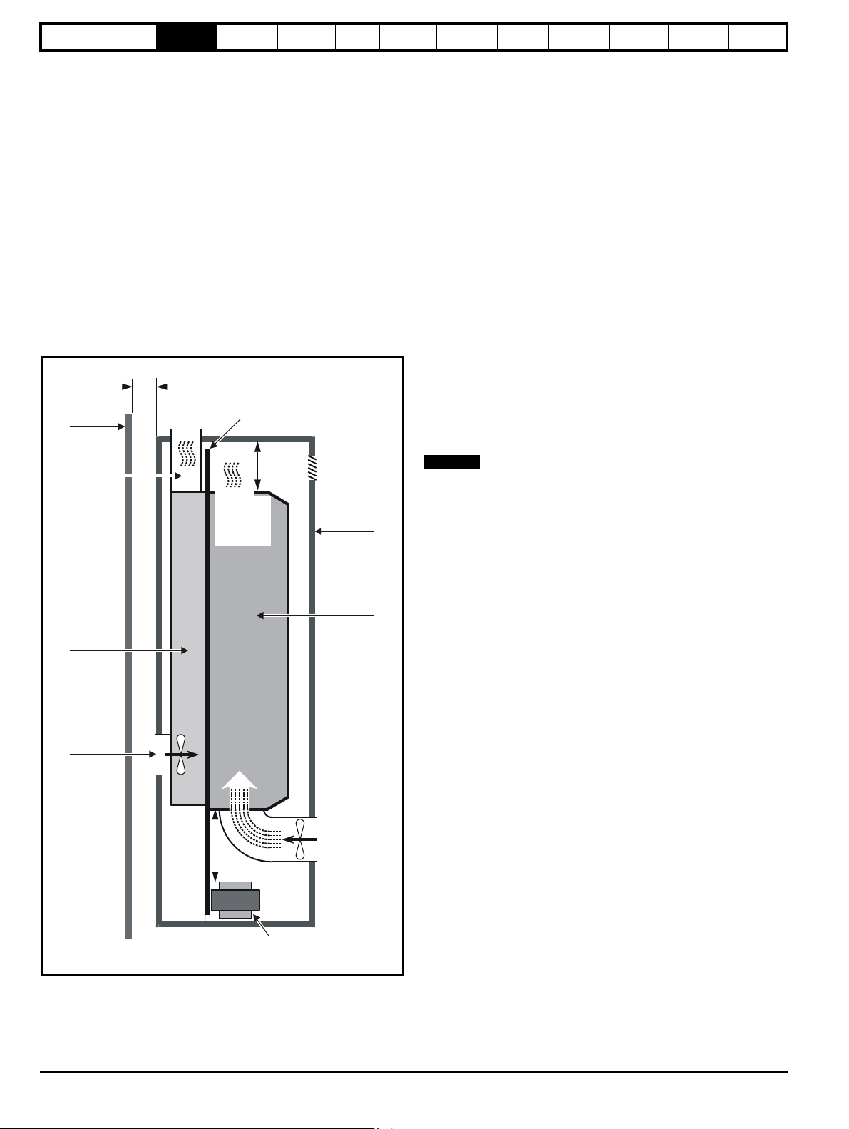
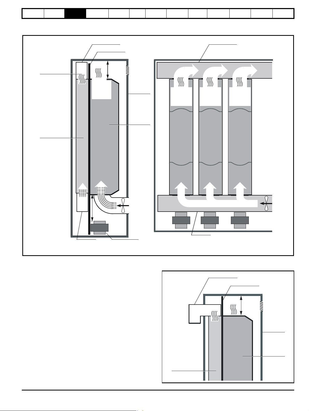
3.8.1 Ventilation requirements for the Size 5 power
Figure 3-16 Typical ventilation arrangement using the internal
module
≥
300mm
(12 in)
Wall
heatsink fan
3
≥
1000m /hr
3
(588ft /min)
≥
7 m/s (23 ft/s)
Back-plate
Optimisation Macros
Advanced
Parameters
Technical
Data
Diagnostics
UL Listing
Information
If a fan is not fitted internally, the air flow must be obtained by an external
fan and ducting. The blanking plate at the lower end of the duct must be
removed in order to expose the inlet port (see Figure 3-17).
The air supply must be obtained from outside the enclosure and the
exhaust air must exit the enclosure. The maximum permissible heatsink
temperature is 95°C (203°F). Take the following precautions to help
ensure this is not exceeded:
1. Ensure the temperature of the air at the inlet port of the heatsink
does not exceed 40°C (104°F).
2. Ensure that the upward flow of the exhaust air from the top of the
heatsink will be unobstructed. Fit additional ducting having the same
cross-sectional area as the heatsink to extract all the exhaust air
from the enclosure.
3. Ensure the volume of the exhaust air is not less than 1,000m
3
/min), equivalent airspeed 7m/s (23 ft/s). Measure the air-flow
(588ft
3
/hr
to ensure it is adequate.
4. If the power module has a ventilation fan fitted in the heatsink, to
ensure that a sufficient amount of air is available to supply the fan,
locate the enclosure at least 300mm (12 in) from a wall or large
object that will be behind the enclosure. Fit a duct between the rear
panel of the enclosure and the inlet port at the rear of the heatsink.
If the power module does not have an internal fan, a forced air-flow
must be ducted into the inlet port at the bottom of the heatsink.
5. Ensure that the exhaust air is not recycled into the inlet port of the
heatsink or into the enclosure.
Exhaust
duct
Heatsink
Inlet duct
3
400m /hr
≥
3
(235 ft /min)
1 m/s
≥
(3.3 ft/s)
≥
150mm (6 in)
≥
150mm
(6 in)
Vent
Enclosure
Power
module
Fan for
cooling the
control
section
NOTE
N
The solutions shown for Unidrive size 5 ventilation are to illustrate the
important points which must be considered. Many variations of this are
possible to suit the specific site conditions.
Sharing choke
(for parallel
operation only)
Cooling the heatsink
When designing the cooling system, allow for the rear of the power
module to produce 4kW of heat. This heat is dissipated in a heatsink that
is inside a vertical duct at the rear of the power module. Forced air-flow
is required through the duct in order to cool the heatsink.
26 Unidrive User Guide
www.controltechniques.com Issue Number: 9
Page 27
Safety
Exh
Exh
≤
Information
Product
Information
Mechanical
Installation
Electrical
Information
Getting
Star ted
Menu 0
Figure 3-17 Typical ventilation arrangement using an external
heatsink fan
Running
the motor
Optimisation Macros
Advanced
Parameters
Technical
Data
Diagnostics
UL Listing
Information
≥
1000m /hr
3
(588ft /min)
≥
7 m/s
(23 ft/s)
Heatsink
aust duct
aust duct
Back-plate
3
≥
3
400m /hr
≥
3
(235 ft /min)
1 m/s
≥
(3.3 ft/s)
150mm
(6 in)
Vent
Enclosure
module
Power
≥
1000m /hr
3
(588ft /min)
≥
7 m/s
(23 ft/s)
3
3
≥
1000m /hr
3
(588ft /min)
≥
7 m/s
(23 ft/s)
≥
1000m /hr
(588ft /min)
≥
7 m/s
(23 ft/s)
3
3
Inlet duct
≥
150mm (6 in)
Fan for
cooling the
control
section
Sharing choke
(for parallel
operation only)
Cooling the control components in the Size 5 power module
The circuit boards, DC-bus capacitors, etc., in the front part of the power
module generate about 700W of heat when the power module is
operating at full load. Since the heatsink fan does not ventilate these
components, a separate air-flow must be used to remove the heat. The
following precautions must be taken:
1. It is recommended that a fan is installed in the lower part of the
enclosure door to drive air into the enclosure. An air vent should be
added to the upper part of the door to remove the exhaust air.
2. It is recommended that the airflow is ducted into the front of the
drive. This airflow must be at least 400m
air speed of 1m/s (3.3ft/s) through the front control section of the
size 5 power module.
If the airflow is not ducted into the front of the drive, the airflow into
the enclosure must be at least 1000m
speed of 7m/s (23ft/s) for a enclosure of 800mm x 800mm
x 2200mm.
3. The maximum temperature of the air in the enclosure must not
exceed 40°C (104°F).
3
/hr (235ft3/min), equivalent
3
/hr (588ft3/min), equivalent air
0
40 C
0
(104 F)
Inlet duct
Inlet duct
Figure 3-18 Alternative location of the exhaust duct in order to
minimize overall height
Exhaust duct
Back-plate
≥
150mm
(6 in)
Vent
Enclosure
Power
module
Heatsink
Unidrive User Guide 27
Issue Number: 9 www.controltechniques.com
Page 28
Safety
0.256
Information
Product
Information
Mechanical
Installation
Electrical
Installation
Getting
Star ted
Menu 0
Running
the motor
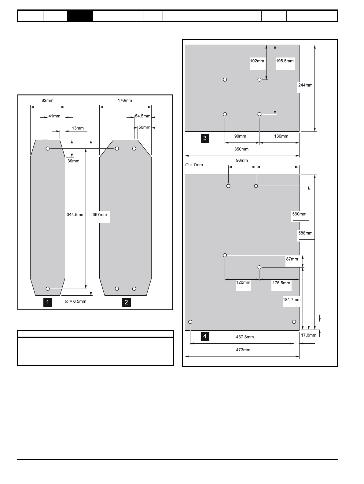
3.9 Baffle plates
When a Unidrive size 1 to 4 is through-panel mounted, the fitting of a
baffle plate causes the heatsink to act as a chimney; this enhances the
air flow along the heatsink fins to aid cooling (this naturally occurs when
the drive is surface mounted).
You may make a baffle plate from any suitable conducting or nonconducting material and attach it to the heatsink by the method
described as follows.
Figure 3-19 Dimensions for the fabrication of baffle plates for
model sizes 1 and 2
3.228in 6.929in
Optimisation Macros
Advanced
Parameters
Technical
Data
Diagnostics
UL Listing
Information
Figure 3-20 Dimensions for the fabrication of baffle plates for
model sizes 3 and 4
4.016in 7.697in
9.606in
1.614in
0.512in
1.535in
13.563in 14.449in
2.146in
1.969
in
0.276in
3.583in 5.118in
13.780in
189.5mm
3.780in
4.724in
7.461in
6.949in
22.047in
23.150in
3.425in
in
7.154in
Attaching a fabricated baffle plate to the heatsink
Table 3-2 Methods of attaching the baffle plate
Model size Method of attachment
1
2
3
4
Use M6 x 12mm max (or equivalent) thread-forming screws to
screw into the holes in the heatsink, or tap the holes to a suitable
Use the surface mounting brackets.
thread size.
17.236in
18.622in
0.693in
76mm
2.992in
3.10 Ambient temperature
The maximum ambient temperature under which the drive can operate
without derating is 40°C.
Derating can be applied to allow operation up to 50°C ambient
temperature.
Please see section 11.1.1 Power and current ratings on page 190 if
derating is required.
28 Unidrive User Guide
www.controltechniques.com Issue Number: 9
Page 29

Safety
Information
Product
Information
Mechanical
Installation
Electrical
Information
Getting
Star ted
Menu 0
Running
the motor
Optimisation Macros
Advanced
Parameters
Technical
Data
3.11 RFI filters
RFI filters are available for all sizes of Unidrive as follows:
Table 3-3 RFI filters
Drive Filter type Schaffner part no. CT part no. Max cable size Weight
UNI1201 to 1205 Bookcase FS5111-10-29 4200-6105
UNI1201 to 1205
Footprint or
Bookcase
FS5101-10-07 4200-6104
UNI2201 to 2202 Bookcase FS5112-16-07 4200-6109
UNI2201 to 2202
Footprint or
Bookcase
FS5106-16-07 4200-6108
UNI2203 Bookcase FS5113-25-29 4200-6114
UNI2203
Footprint or
Bookcase
FS5106-25-07 4200-6113
UNI3201 to 3202 Bookcase FS5113-50-53 4200-6116
UNI3203 Bookcase FS5113-63-34 4200-6117
UNI3204 Bookcase FS5113-100-35 4200-6106
UNI1401 to 1405 Bookcase FS5111-10-29 4200-6105
UNI1401 - 1405
Footprint or
Bookcase
FS5101-10-07 4200-6104
UNI2401 Bookcase FS5112-16-07 4200-6109
UNI2401
Footprint or
Bookcase
FS5106-16-07 4200-6108
UNI2402 to 2403 Bookcase FS5113-25-29 4200-6114
UNI2402 to 2403
Footprint or
Bookcase
FS5106-25-07 4200-6113
UNI3401 to 3403 Bookcase FS5113-50-53 4200-6116
UNI3404 Bookcase FS5113-63-34 4200-6117
UNI3405 Bookcase FS5113-100-35 4200-6106
UNI4401 to 4402 Bookcase FS5113-150-40 4200-6107
UNI4403 to 4404 Bookcase FS5113-180-40 4200-6111
UNI4405 Bookcase FS5113-220-37 4200-6112
4 mm
4 mm
4 mm
4 mm
4 mm
4 mm
10 mm
10 mm
50 mm
4 mm
4 mm
4 mm
4 mm
4 mm
4 mm
10 mm
10 mm
50 mm
95 mm
95 mm
150 mm
2
10 AWG
2
10 AWG
2
10 AWG
2
10 AWG
2
10 AWG
2
10 AWG
2
6 AWG
2
6 AWG
2
1/0 AWG
2
10 AWG
2
10 AWG
2
10 AWG
2
10 AWG
2
10 AWG
2
10 AWG
2
6 AWG
2
6 AWG
2
1/0 AWG
2
4/0 AWG
2
4/0 AWG
2
6/0 AWG
UNI5401 Bookcase FS113-300-99 4200-6115 M12 stud 16kg (35lb)
The RFI filters can be surface-mounted only.
Mount the RFI filter following the guidelines in Figure 4-12 EMC
compliance on page 48.
1.4kg (3lb)
2.1kg (5lb)
2.7kg (6lb)
2.1kg (5lb)
2.7kg (6lb)
2.1kg (5lb)
3.8kg (9lb)
3.8kg (9lb)
7.8kg (17lb)
1.4kg (3lb)
2.1kg (5lb)
2.7kg (6lb)
2.1kg (5lb)
2.7kg (6lb)
2.1kg (5lb)
3.8kg (9lb)
3.8kg (9lb)
7.8kg (17lb)
7.8kg (17lb)
15kg (33lb)
15kg (33lb)
Diagnostics
UL Listing
Information
Unidrive User Guide 29
Issue Number: 9 www.controltechniques.com
Page 30
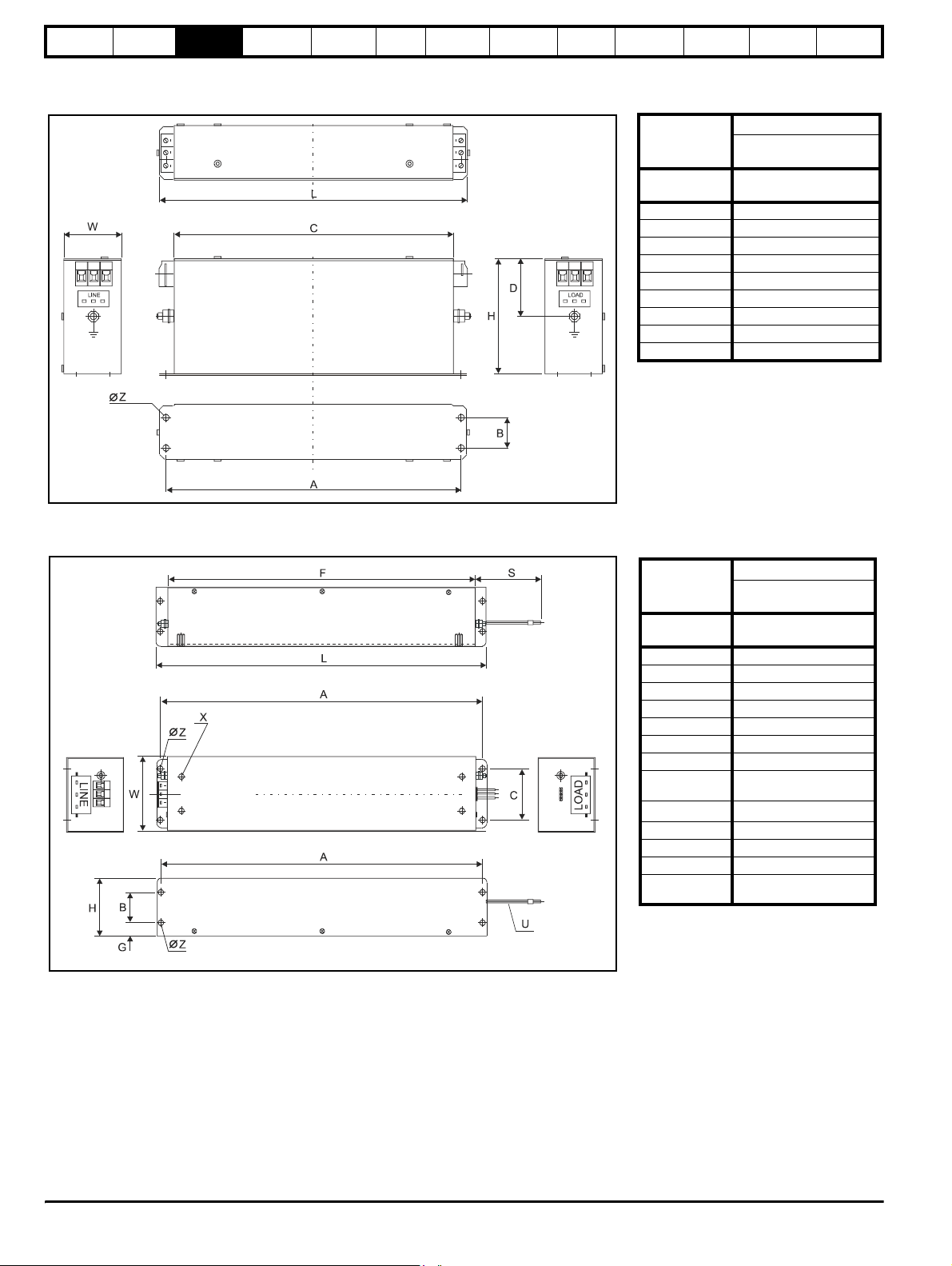
Safety
Information
Product
Information
Mechanical
Installation
Electrical
Installation
Getting
Star ted
3.11.1 Unidrive size 1 filters
Figure 3-21 Unidrive size 1 bookcase mounted filter
Menu 0
Running
the motor
Optimisation Macros
Advanced
Parameters
Ground Terminal M5
Technical
Data
Dimension
Model
A 230mm (9.055in)
B 25mm (0.984in)
C 218mm (8.583in)
D 47.5mm (1.870in)
H 95mm (3.740in)
L 240mm (9.449in)
W 45mm (1.772in)
Z 4.5mm (0.177in)
Diagnostics
UNI1201 to UNI1205
UNI1401 to UNI1405
UL Listing
Information
RFI Filter
4200-6105
FS5111-10-29
Figure 3-22 Unidrive size 1 footprint or bookcase mounted filter
RFI Filter
Dimension
Model
A 380mm (14.961in)
B 35mm (1.378in)
C 60mm (2.362in)
F 364mm (14.331in)
G 16.5mm (0.650in)
H 68mm (2.677in)
L 390mm (15.354in)
S
U
W 85mm (3.346in)
XM6 (4x)
Z 5.5mm (0.217in)
Ground
Terminal
4200-6104
FS5101-10-07
UNI1201 to UNI1205
UNI1401 to UNI1405
300mm ±5mm
(11.811in ±0.197in)
3x 2.5mm
2
(AWG14)
M5
30 Unidrive User Guide
www.controltechniques.com Issue Number: 9
Page 31

Safety
Information
Product
Information
Mechanical
Installation
Electrical
Information
Getting
Star ted
Menu 0
Running
the motor
Optimisation Macros
3.11.2 Unidrive size 2 filters
Figure 3-23 Unidrive size 2 (UNI2201 to UNI2202 and UNI2401) bookcase mounted filter
Advanced
Parameters
Technical
Data
Diagnostics
Dimension
Model
UNI2201 to UNI2202
A 380mm (14.961in)
B 35mm (1.378in)
C 60mm (2.362in)
F 364mm (14.331in)
G 16.5mm (0.650in)
H 68mm (2.677in)
L 390mm (15.354in)
S
U
(11.811in ±0.197in)
3x 2.5mm
W 85mm (3.346in)
Z 5.5mm (0.217in)
Ground Terminal M5
UL Listing
Information
RFI Filter
4200-6109
FS5112-16-07
UNI2401
300mm ±5mm
2
(AWG14)
Figure 3-24 Unidrive size 2 (UNI2203, and UNI2402 to UNI2403) bookcase mounted filter
RFI Filter
Dimension
Model
4200-6114
FS5113-25-29
UNI2203
UNI2402 to UNI2403
A 245mm (9.646in)
B 45mm (1.772in)
C 230mm (9.055in)
D 13mm (0.512in)
H 95mm (3.740in)
L 255mm (10.039in)
W 73mm (2.874in)
Z 4.5mm (0.177in)
Ground Terminal M5
Unidrive User Guide 31
Issue Number: 9 www.controltechniques.com
Page 32

Safety
Information
Product
Information
Mechanical
Installation
Electrical
Installation
Getting
Star ted
Menu 0
Figure 3-25 Unidrive size 2 footprint or bookcase mounted filters
Running
the motor
Optimisation Macros
Dimension
Model
Ground
Terminal
Advanced
Parameters
A 385mm (15.157in) 385mm (15.157in)
B 35mm (1.378in) 35mm (1.378in)
C 120mm (4.724in) 120mm (4.724in)
D 364mm (14.331in) 364mm (14.331in)
E 16.5mm (0.650in) 16.5mm (0.650in)
H 68mm (2.677in) 68mm (2.677in)
J
U
W 180mm (7.087in) 180mm (7.087in)
X M6 (4x) M6 (4x)
Z 5.5mm (0.217in) 5.5mm (0.217in)
Technical
Data
RFI Filters
4200-6108
FS5106-16-07
UNI2201 to UNI2202
UNI2401
300mm ±5mm
(11.811in ±0.197in)
2
(AWG12) 3x 4mm2 (AWG12)
3x 4mm
M5 M5
Diagnostics
UNI2402 to UNI2403
(11.811in ±0.197in)
UL Listing
Information
4200-6113
FS5106-25-07
UNI2203
300mm ±5mm
3.11.3 Unidrive size 3 and 4 filters
Ensure the LOAD terminals face the drive.
Figure 3-26 Unidrive size 3 (UNI3201 to UNI3202, UNI3401 to UNI3403) bookcase mounted filter
Dimension
Model
A 275mm (10.827in)
B 50mm (1.969in)
C 259.5mm (10.217in)
D 290mm (11.417in)
H 100mm (3.937in)
L 337mm (13.268in)
W 90mm (3.543in)
Z 7mm (0.276in)
Ground Terminal M5
RFI Filter
4200-6116
FS5113-50-53
UNI3201 to UNI3202, UNI3401 to
UNI3403
32 Unidrive User Guide
www.controltechniques.com Issue Number: 9
Page 33

Safety
Information
Product
Information
Mechanical
Installation
Electrical
Information
Getting
Star ted
Menu 0
Running
the motor
Optimisation Macros
Advanced
Parameters
Figure 3-27 Unidrive size 3 (UNI3203 to UNI3204, UNI3404 to UNI3405) & size 4 bookcase mounted filter
Technical
Data
Diagnostics
UL Listing
Information
RFI Filters
Dimension
Model
4200-6117
FS5113-63-34
UNI3203
UNI3404
4200-6106
FS5113-100-35
UNI3204
UNI3405
4200-6107
FS5113-150-40
4200-6111
FS5113-180-40
4200-6112
FS5113-220-37
UNI4401 to UNI4402 UNI4403 to UNI4404 UNI4405
A 315mm (12.402in) 310mm (12.205in) 330mm (12.992in) 420mm (16.535in) 420mm (16.535in)
B 105mm (4.134in) 105mm (4.134in) 120mm (4.724in) 110mm (4.331in) 110mm (4.331in)
C 300mm (11.811in) 294mm (11.575in) 314mm (12.362in) 400mm (15.748in) 375mm (14.764in)
G 330mm (12.992in) 325mm (12.795in) 345mm (13.583in) 440mm (17.323in) 440mm (17.323in)
H 103mm (4.055in) 107mm (4.213in) 135mm (5.315in) 157mm (6.181in) 157mm (6.181in)
L 377mm (14.843in) 380mm (14.961in) 414mm (16.299in) 502mm (19.764in) 523mm (20.591in)
W 150mm (5.906in) 150mm (5.906in) 150mm (5.906in) 170mm (6.693in) 170mm (6.693in)
Z 7mm (0.276in) 7mm (0.276in) 7mm (0.276in) 8.5mm (0.335in) 8.5mm (0.335in)
Ground Terminal M6 M8 M10 M12 M12
Unidrive User Guide 33
Issue Number: 9 www.controltechniques.com
Page 34

Safety
Information
Product
Information
Mechanical
Installation
Electrical
Installation
Getting
Star ted
Unidrive Size 5 bookcase mounted filter
Ensure the LOAD terminals face the drive.
Figure 3-28 Unidrive size 5 bookcase mounted filter
G
C
∅
Z
LINE
A
L
Menu 0
Running
the motor
LOAD
Optimisation Macros
BW
Advanced
Parameters
Dimension
Ground Terminal M12
Technical
Data
Model
A 470mm (18.504in)
B 170mm (6.693in)
C 450mm (17.717in)
G 490mm (19.291in)
H 156mm (6.142in)
L 655mm (25.787in)
W 230mm (9.055n)
Z 8.5mm (0.335in)
Diagnostics
RFI Filters
4200-6115
FS5113-300-99
UNI3203
UNI3404
UL Listing
Information
H
34 Unidrive User Guide
www.controltechniques.com Issue Number: 9
Page 35

Safety
Information
Product
Information
Mechanical
Installation
Electrical
Information
Getting
Star ted
Menu 0
3.12 Power terminals
3.12.1 Location of power and ground terminals
Figure 3-29 Locations of the power and ground terminals on
Unidrive Size 1 to 4
2mm
3mm
T25 Torx or
10mm flat
Running
the motor
Optimisation Macros
Advanced
Parameters
Technical
Data
Diagnostics
Figure 3-30 Locations of the power and ground terminals on the
Size 5 power module
AC supply connections
L1 L2 L3
17mm
IN96
Phase-control board
DC-bus choke
UL Listing
Information
17mm
−
M4
pozidriv
screw
Fan AC-supply
connections
DC bus
IN95
Interface board
UVW
Motor connections
+DC bus
17mm
Unidrive User Guide 35
Issue Number: 9 www.controltechniques.com
Page 36

Safety
Information
Product
Information
Mechanical
Installation
Electrical
Installation
Getting
Star ted
Menu 0
Running
the motor
Optimisation Macros
Advanced
Parameters
Technical
Data
Diagnostics
UL Listing
Information
3.12.2 Terminal sizes and torque settings
To avoid a fire hazard and maintain validity of the UL listing,
adhere to the specified tightening torques for the power and
WARNING
Table 3-4 Drive control terminal data
Table 3-5 Drive power terminal data
Model size AC terminals DC terminals Ground terminal
Table 3-6 Size 5 fan supply connection
Terminal block M4 Pozidriv screw 0.5 N m 4.4 lb in
ground terminals. Refer to the following tables.
Model Connection type Torque setting
All Plug-in terminal block 0.5 N m 4.4 lb in
1
2
3
4
5
Plug-in terminal block
0.5 N m / 4.4 lb in
Plug-in terminal block
0.5 N m / 4.4 lb in
M10 stud
15 N m / 11 lb ft
M10 stud
15 N m / 11 lb ft
M10 bolt & nut 25
N m / 22.1 lb ft
Torque tolerance ±10%
Type Torque setting
M10 hole
25 N m / 22.1 lb ft
M4 (Torx/slot-head screw)
3 N m / 2.2 lb ft
M4 (Torx/slot-head screw)
3 N m / 2.2 lb ft
M10 stud
15 N m / 11 lb ft
M10 stud
15 N m / 11 lb ft
M10 stud
25 N m / 22.1 lb ft
3.13 Routine maintenance
The drive should be installed in a cool, clean, well ventilated location.
Contact of moisture and dust with the drive should be prevented.
Regular checks of the following should be carried out to ensure drive /
installation reliability is maximised:
Environment
Ambient temperature
Dust
Moisture
Enclosure
Enclosure door filters
Electrical
Screw connections Ensure all screw terminals remain tight
Crimp terminals
Cables Check all cables for signs of damage
Ensure the enclosure temperature remains at or below
40°C (50°C when derating applied)
Ensure the drive remains dust free – check that the
drive fan is not gathering dust. The lifetime of the fan is
reduced in dusty environments.
Ensure the drive enclosure shows no signs of
condensation
Ensure filters are not blocked and that air is free to
flow
Ensure all crimp terminals remains tight – check for
any discolouration which could indicate overheating
Table 3-7 RFI Filter terminal data
CT
part
number
4200-6104 FS5101-10-07
4200-6105 FS5111-10-29
4200-6108 FS5106-16-07
4200-6109 FS5112-16-07
4200-6113 FS5106-25-07
4200-6114 FS5113-25-29
4200-6116 FS5113-50-53
4200-6117 FS5113-63-34
4200-6106 FS5113-100-35
4200-6107 FS5113-150-40
4200-6111 FS5113-180-40
4200-6112 FS5113-220-37
4200-6115 FS5113-300-99 M12 stud
Schaffner
part
number
connections
Max cable
size
4 mm
10 AWG
4 mm
10 AWG
4 mm2
10 AWG
4 mm2
10 AWG
4 mm
10 AWG
4 mm
10 AWG
10 mm
6 AWG
10 mm
6 AWG
50 mm
1/0 AWG
95 mm2
4/0 AWG
95 mm
4/0 AWG
150 mm2
6/0 AWG
Power
Tor que Si ze To rqu e
2
0.8 N m
7.1 lb in
2
0.8 N m
7.1 lb in
0.8 N m
7.1 lb in
0.8 N m
7.1 lb in
2
0.8 N m
7.1 lb in
2
0.8 N m
7.1 lb in
2
4.5 N m
3.3 lb ft
2
4.5 N m
3.3 lb ft
2
8.0 N m
5.9 lb ft
20.0 N m
14.7 lb ft
2
20.0 N m
14.7 lb ft
30.0 N m
22.1 lb ft
30.0 N m
22.1 lb ft
Ground
connections
M5
19.5 lb in
M5
19.5 lb in
M5
19.5 lb in
M5
19.5 lb in
M5
19.5 lb in
M5
19.5 lb in
M5
19.5 lb in
M6
M8
18.0 N m
M10
20.0 N m
M12
20.0 N m
M12
M12
20.0 N m
stud
2.2 N m
2.2 N m
2.2 N m
2.2 N m
2.2 N m
2.2 N m
2.2 N m
4.0 N m
2.9 lb ft
9.0 N m
6.6 lb ft
13.3 lb ft
14.7 lb ft
14.7 lb ft
14.7 lb ft
For all the RFI filters, except the size 5 (4200-6115), the power
connections are screw terminals and the ground connections are stud
terminals.
36 Unidrive User Guide
www.controltechniques.com Issue Number: 9
Page 37

Safety
Ground
Information
Product
Information
Mechanical
Installation
Electrical
Installation
Getting
Star ted
Menu 0
Running
the motor
Optimisation Macros
Advanced
Parameters
Technical
Data
Diagnostics
UL Listing
Information
4 Electrical Installation
This chapter describes the how to electrically install the drive. Key
features include:
• EMC compliance with shielding / grounding accessories
• Product rating, fusing and cabling information
• Brake resistor details (selection / ratings)
Electric shock risk
The voltages present in the following locations can cause
severe electric shock and may be lethal:
WARNING
WARNING
WARNING
WARNING
• AC supply cables and connections
• Output cables and connections
• Many internal parts of the drive, and external option
units
Isolation device
The AC supply must be disconnected from the drive using
an approved isolation device before any cover is removed
from the drive or before any servicing work is performed.
STOP function
The STOP function does not remove dangerous voltages
from the drive or any external option units.
Stored charge
The drive contains capacitors that remain charged to a
potentially lethal voltage after the AC supply has been
disconnected. If the drive has been energised, the AC
supply must be isolated at least ten minutes before work
may continue.
Normally, the capacitors are discharged by an internal
resistor. Under certain, unusual fault conditions, it is possible
that the capacitors may fail to discharge, or be prevented
from being discharged by a voltage applied to the output
terminals. If the drive has failed in a manner that causes the
display to go blank immediately, it is possible the capacitors
will not be discharged. In this case, consult Control
Techniques or their authorised distributor.
4.1 Power connections
Figure 4-1 Unidrive Size 1 to 2 power connections
L2L1 L3 U V W
Thermal
overload
protection
device
Fuses
Optional RFI
filter
Optional
line reactor
L1 L2
Mains
Supply
L3
Supply
Motor
Optional ground
connection
Braking
resistor
_
+
Equipment supplied by plug and socket
Special attention must be given if the drive is installed in
equipment which is connected to the AC supply by a plug
WARNING
and socket. The AC supply terminals of the drive are
connected to the internal capacitors through rectifier diodes
which are not intended to give safety isolation. If the plug
terminals can be touched when the plug is disconnected
from the socket, a means of automatically isolating the plug
from the drive must be used (e.g. a latching relay).
Permanent-magnet motors
Permanent-magnet motors generate electrical power if they
are rotated, even when the supply to the drive is
WARNING
disconnected. If that happens then the drive will become
energised through its motor terminals. If the motor load is
capable of rotating the motor when the supply is
disconnected, then the motor must be isolated from the drive
before gaining access to any live parts.
NOTE
N
Drives are suitable for use on supplies of installation category III and
lower, according to IEC 60664-1. This means they may be connected
permanently to the supply at its origin in a building, but for outdoor
installation additional overvoltage suppression (transient voltage surge
suppression) must be provided to reduce category IV to category III.
Unidrive User Guide 37
Issue Number: 9 www.controltechniques.com
Page 38

Safety
Ground
Information
Product
Information
Mechanical
Installation
Electrical
Installation
Getting
Star ted
Figure 4-2 Unidrive Size 3 to 4 power connections
Menu 0
Running
the motor
Optimisation Macros
Advanced
Parameters
Technical
Data
Diagnostics
UL Listing
Information
Fuses
L2L1 L3 U V W
Optional RFI
filter
Optional
line reactor
L1 L2
Mains
Supply
L3
Supply
Motor
Optional ground
connection
+
Thermal
overload
protection
device
A thermal overload protection device should be connected as shown in
Figure 4-7 on page 44 and must interrupt the AC supply on tripping. This
applies to all sizes of Unidrive where a braking resistor is used.
Braking
resistor
_
38 Unidrive User Guide
www.controltechniques.com Issue Number: 9
Page 39

Safety
Information
Product
Information
Mechanical
Installation
Electrical
Installation
Getting
Star ted
Menu 0
Running
the motor
4.1.1 Unidrive size 5 control / power module connections
Figure 4-3 Unidrive size 5 ribbon cable and sharing choke inter-
L3
L2
L1
Ground
Contactor / Isolator
Fuses Fuses
Optimisation Macros
Advanced
Parameters
Technical
Data
Diagnostics
UL Listing
Information
Control
module
10-way
Power
module
16-way
Optional line reactor
Optional RFI filter
IN96
Phase-control board
DC-bus choke
IN95
Interface board
10-way
Power
module
16-way
Optional line reactor
Optional RFI filter
IN96
Phase-control board
DC-bus choke
IN95
Interface board
26-way
-DC -DC
AC supply for fan
NOTE
(when fitted)
N
UWVUWV
Sharing choke Sharing choke
When using Unidrive size 5 with multiple power modules, a sharing
choke must be fitted on the output of each drive as shown. The
specification for the choke is given in Chapter 11 Technical Data on
page 190 and it should be sourced locally.
+DC
26-way
WARNING
+DC
Contactor /
Isolator
W
V
U
Ensure that the fan and power module can be isolated from
the AC supplies. Isolation from the supplies must be
interlocked, or a warning must be displayed indicating that
two separate supplies are present.
Unidrive User Guide 39
Issue Number: 9 www.controltechniques.com
Page 40

Safety
Information
Product
Information
Mechanical
Installation
Electrical
Installation
Getting
Star ted
Menu 0
Running
the motor
Optimisation Macros
Advanced
Parameters
Technical
Data
Diagnostics
UL Listing
Information
4.2 AC supply requirements
Voltage:
UNIX20XLV 200V to 240V ±10%
UNIX40X 380V to 480V ±10%
Number of phases: 3
Minimum supply imbalance: 2% negative phase sequence (equivalent to
3% voltage imbalance between phases)
Frequency range: 48Hz to 65Hz
Maximum supply fault current:
Frame size Symmetrical fault level (kA)
1, 2, 3 5
410
518
4.2.1 IT supplies
Special considerations are required when the neutral point of the
distribution winding of the supply transformer is not directly grounded.
Before using the drive on such a supply, please contact the supplier of
the drive.
4.2.2 Installation category
Drives are suitable for use on supplies of installation category III and
lower, according to IEC60664-1. This means they may be connected
permanently to the supply at its origin in a building, but for outdoor
installation additional over-voltage suppression (transient voltage surge
suppression) must be provided to reduce category IV to category III.
4.2.3 Supplies requiring line reactors
Input line reactors reduce the risk of damage to the drive resulting from
poor phase balance or severe disturbances on the supply network.
Where line reactors are to be used, reactance values of approximately
2% are recommended. Higher values may be used if necessary, but may
result in a loss of drive output (reduced torque at high speed) because of
the voltage drop.
For all drive ratings, 2% line reactors permit drives to be used with a
supply unbalance of up to 3.5% negative phase sequence (equivalent to
5% voltage imbalance between phases).
Severe disturbances may be caused by the following factors, for
example:
• Power factor correction equipment connected close to the drive.
• Large DC drives having no or inadequate line reactors connected to
the supply.
• Direct-on-line started motor(s) connected to the supply such that
when any of these motors are started, the voltage dip exceeds 20%
Such disturbances may cause excessive peak currents to flow in the
input power circuit of the drive. This may cause nuisance tripping, or in
extreme cases, failure of the drive.
Drives of low power rating may also be susceptible to disturbance when
connected to supplies with a high rated capacity.
Line reactors are particularly recommended for use with the following
drive models when one of the above factors exists, or when the supply
capacity exceeds 175kVA:
UNI1201 UNI1202 UNI1203 UNI1204
UNI1401 UNI1402 UNI1403 UNI1404
Model sizes 1205, 1405 and larger have an internal DC choke so they
do not require AC line reactors except for cases of excessive phase
unbalance or extreme supply conditions.
When required, each drive must have its own reactor(s). Three individual
reactors or a single three-phase reactor should be used.
Reactor current ratings
The current rating of the line reactors should be as follows:
Continuous current rating:
Not less than the continuous input current rating of the drive
Repetitive peak current rating:
Not less than twice the continuous input current rating of the drive
4.2.4 Input inductor calculation.
To calculate the inductance required (at Y%), use the following equation:
Y
V
-------
1
-----------
×=
2π fl
3
----------
L
100
×
Where:
I = drive rated input current (A)
L = inductance (H)
f = supply frequency (Hz)
V = voltage between lines
4.3 Supplying the drive with DC / DC bus paralleling
The drive may be supplied with DC instead of 3 phase AC. For further
information please refer to the supplier of your drive.
Connecting of the DC bus between several drives is typically used to:
1. Return energy from a drive which is being overhauled by the load to
a second motoring drive.
2. Allow the use of one braking resistor to dissipate regenerative
energy from several drives.
There are limitations to the combinations of drives which can be used in
this configuration.
For application data, contact the supplier of the drive.
4.4 Ratings
The input current is affected by the supply voltage and impedance.
4.4.1 Typical input current
The values of typical input current are given to aid calculations for power
flow and power loss.
The values of typical input current are stated for a balanced supply.
4.4.2 Maximum continuous input current
The values of maximum continuous input current are given to aid the
selection of cables and fuses. These values are stated for the worst case
condition with the unusual combination of stiff supply with bad balance.
The value stated for the maximum continuous input current would only
be seen in one of the input phases. The current in the other two phases
would be significantly lower.
The values of maximum input current are stated for a supply with a 2%
negative phase-sequence imbalance and rated at the maximum supply
fault current given in Table 4-1.
40 Unidrive User Guide
www.controltechniques.com Issue Number: 9
Page 41
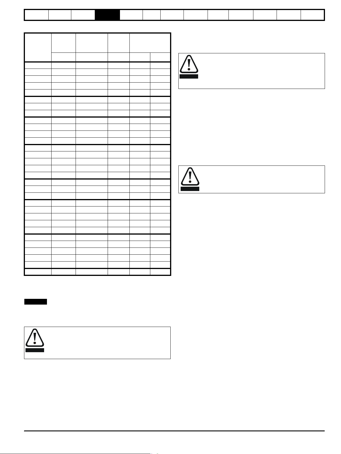
Safety
Information
Product
Information
Mechanical
Installation
Electrical
Installation
Getting
Star ted
Menu 0
Running
the motor
Optimisation Macros
Advanced
Parameters
Technical
Data
Diagnostics
UL Listing
Information
Table 4-1 Input current, fuse and cable size ratings
Maximum
continuous
input current
Fuse
rating
Cable size
2
mm
AWG
Model
Typical
input
current
AAA
UNI1201 2.4 4.0 6.0 1.5 16
UNI1202 3.5 6.0 10 2.5 14
UNI1203 4.6 8.0 10 2.5 14
UNI1204 6.5 10 10 2.5 14
UNI1205 8.6 12.5 16 2.5 14
UNI2201 10.8 13.9 16 2.5 14
UNI2202 14.3 16.9 20 4 10
UNI2203 19.8 27 35 4 10
UNI3201 26 28 40 6 8
UNI3202 39 43 60 10 6
UNI3203 53 56 70 16 4
UNI3204 78 84 80 25 4
UNI1401 3.0 4.5 6.0 1.5 16
UNI1402 4.3 5.5 10 2.5 14
UNI1403 5.8 6.8 10 2.5 14
UNI1404 8.2 8.6 10 2.5 14
UNI1405 10 12 16 2.5 14
UNI2401 13 16 16 2.5 14
UNI2402 17 20 20 4 10
UNI2403 21 25 35 4 10
UNI3401 27 34 40 6 8
UNI3402 32 39 50 10 6
UNI3403 40 53 60 10 6
UNI3404 52 66 70 16 4
UNI3405 66 82 80 25 4
UNI4401 76 98 100 35 2
UNI4402 91 114 125 35 2
UNI4403 123 152 160 50 0
UNI4404 145 205 200 70 2/0
UNI4405 181 224 250 95 3/0
UNI5401 280 321 450 120 4/0
The recommended cable sizes above are only a guide. Refer to local
wiring regulations for the correct size of cables. In some cases a larger
cable is required to avoid excessive voltage drop.
NOTE
N
UL listing is dependent on the use of the correct type of UL-listed fuse,
and applies when symmetrical short-circuit current does not exceed 5kA
for sizes 1 to 3, 10 kA for size 4 or 18kA for size 5.
Fuses
The AC supply to the drive must be fitted with suitable
protection against overload and short-circuits. Table 4-1
WARNING
shows recommended fuse ratings. Failure to observe this
requirement will cause risk of fire.
A fuse or other protection must be included in all live connections to the
AC supply.
An MCB (miniature circuit breaker) or MCCB (moulded case circuit
breaker) with type C tripping characteristics and the same rating as the
fuse(s), may be used in place of the fuse(s), on condition that the fault
current clearing capacity is sufficient for the installation.
4.4.3 Fuse Types
The fuse voltage rating must be suitable for the drive supply voltage.
• Europe: Type gG HRC industrial fuses to IEC60269 (BS88)
• USA: Class CC fuses up to 30A, Class J above 30A
4.4.4 Ground connections
The drive must be connected to the system ground of the AC supply.
The ground wiring must conform to local regulations and codes of
practice.
The ground loop impedance must conform to the
requirements of local safety regulations.The drive must be
grounded by a connection capable of carrying the
WARNING
prospective fault current until the protective device (fuse,
etc.) disconnects the AC supply.The ground connections
must be inspected and tested at appropriate intervals.
4.4.5 Main AC supply contactor
The recommended AC supply contactor type for all sizes is AC1.
4.5 Output circuit and motor protection
The output circuit has fast-acting electronic short-circuit protection which
limits the fault current to typically no more than five times the rated
output current, and interrupts the current in approximately 20µs. No
additional short-circuit protection devices are required.
The drive provides overload protection for the motor and its cable. For
this to be effective, Pr 0.46 Motor rated current must be set to suit the
motor.
Pr 0.46 Motor rated current must be set correctly to avoid a
risk of fire in the event of motor overload.
WARNING
There is also provision for the use of a motor thermistor to prevent
overheating of the motor, e.g. due to loss of cooling.
4.5.1 Cable types and lengths
Since capacitance in the motor cable causes loading on the output of the
drive, ensure the cable length does not exceed the values given in Table
4-2 and Table 4-3.
Use 105°C (221°F) (UL 60/75°C temp rise) PVC-insulated cable with
copper conductors having a suitable voltage rating, for the following
power connections:
• AC supply to external EMC filter (when used)
• AC supply (or external EMC filter) to drive
• Drive to motor
• Drive to braking resistor
Unidrive User Guide 41
Issue Number: 9 www.controltechniques.com
Page 42

Safety
Information
Product
Information
Mechanical
Installation
Electrical
Installation
Getting
Star ted
Table 4-2 Maximum motor cable lengths (200V drives)
200V Nominal AC supply voltage
Maximum permissible motor cable length
Model
(PWM switching frequency of 3kHz)
mft
UNI1201 65 210
UNI1202 100 330
UNI1203 130 430
UNI1204 200 660
UNI1205 300 990
UNI2201
300 990UNI2202
UNI2203
UNI3201
UNI3202
UNI3203
200 660
UNI3204
Menu 0
Running
the motor
Optimisation Macros
Advanced
Parameters
Technical
Data
Diagnostics
The maximum cable length is reduced from that shown in the table
under the following conditions:
• PWM switching frequency exceeding 3kHz in model sizes 3 and
4
The maximum cable length is reduced in proportion to the increase
in PWM switching frequency, e.g. at 9kHz, the maximum length is
1
/3 of that shown.
• High-capacitance cables
Most cables have an insulating jacket between the cores and the
armour or shield; these cables have a low capacitance and are
recommended. Cables that do not have an insulating jacket tend to
have high capacitance; if a cable of this type is used, the maximum
cable length is half that quoted in the table. (Figure 4-4 shows how
to identify the two types.)
Figure 4-4 Cable construction influencing the capacitance
UL Listing
Information
Table 4-3 Maximum motor cable lengths (400V drives)
Model
400V Nominal AC supply
voltage
Maximum permissible motor cable length
480V Nominal AC supply
voltage
(PWM switching frequency of 3kHz)
mftmft
UNI1401 65 210 50 160
UNI1402 100 330 75 250
UNI1403 130 430 100 330
UNI1404 200 660 150 490
UNI1405 300 990 250 820
UNI2401
300 990 300 990UNI2402
UNI2403
UNI3401
UNI3402
UNI3403
UNI3404
UNI3405
UNI4401
200 660 124 410
UNI4402
UNI4403
UNI4404
UNI4405
UNI5401 300 990 300 990
UNI5402 600 1980 600 1980
UNI5403 900 2970 900 2970
UNI5404 1200 3960 1200 3960
UNI5405 1500 4950 1500 4950
UNI5406 1800 5940 1800 5940
UNI5407 2100 6930 2100 6930
UNI5408 2400 7920 2400 7920
• Cable lengths in excess of the specified values may be used only
when special techniques are adopted; refer to the supplier of the
drive.
• The default switching frequency for all versions of Unidrive is 3kHz,
except Unidrive LFT, which is 9kHz.
Normal capacitance
Shield or armour
separated from the cores
High capacitance
Shield or armour close
to the cores
The capacitance measured above is from one line to all others and is
obtainable from the cable manufacturer. This means the capacitance
from one core to all the other cores and the screen shorted together.
4.5.2 Multiple motors
Open-loop only
If the drive is to control more than one motor, make connections as
shown in Figure 4-5 and Figure 4-6. The maximum cable lengths given
in Table 4-2 and Table 4-3 apply to the total length of cable from the drive
to the farthest motor.
It is recommended that each motor is connected through a protection
relay since the drive cannot protect each motor individually. For star
connection, a sinusoidal filter or an output inductor must be connected
as shown in Figure 4-5 and Figure 4-6, even when the cable lengths are
less than the maximum permissible. For details, of inductor sizes refer to
the supplier of the drive.
42 Unidrive User Guide
www.controltechniques.com Issue Number: 9
Page 43

Safety
Information
Product
Information
Mechanical
Installation
Electrical
Installation
Getting
Star ted
Menu 0
Figure 4-5 Preferred chain connection for multiple motors
Motor protection
relay
Chain connection (preferred)
Running
the motor
Optimisation Macros
Advanced
Parameters
Technical
Data
Diagnostics
The default setting of the motor rated voltage parameter is the same as
the drive rated voltage
i.e. 400V drive 400V rated voltage
200V drive 200V rated voltage
A typical 3 phase motor would be connected in star for 400V operation
or delta for 200V operation however variations on this are common
i.e. star 690V delta 400V
Incorrect connection of the windings will lead to severe under or over
fluxing of the motor, leading to a very poor output torque or motor
saturation and over-heating respectively.
4.5.4 Output contactor
If the cable between the drive and the motor is to be
interrupted by a contactor or circuit breaker, ensure that the
drive is disabled before the contactor or circuit breaker is
WARNING
A contactor is sometimes required to be fitted between the drive and
motor for safety isolation purposes.
The recommended motor contactor is the AC3 type.
Switching of an output contactor should only occur when the output of
the drive is disabled.
Opening or closing of the contactor with the drive enabled will lead to:
1. OI.AC trips (which cannot be reset for 10 seconds)
2. High levels of RFI noise emission
3. Increased contactor wear and tear
For more information please contact the supplier of the drive.
opened or closed. Severe arcing may occur if this circuit is
interrupted with the motor running at high current and low
speed.
UL Listing
Information
Figure 4-6 Alternative connection for multiple motors
Motor protection
relay
Star connection
Inductor
4.5.3 Star / delta motor operation
The voltage rating for star and delta connections of the motor should
always be checked before attempting to run the motor.
4.6 Braking
Internal connection does not require the cable to be armoured or
shielded.
In-built in the Unidrive software is overload protection for the brake
resistor. In order to enable and set-up this function, it is necessary to
enter two values into the drive:
• Resistor short-time overload time (Pr 10.30)
• Resistor minimum time between repeated short-time overloads (Pr
10.31)
This data is available from the manufacturer of the braking resistors.
4.6.1 Minimum resistances and power ratings
Table 4-4 Minimum resistance values and peak power rating for
The minimum resistance allows the braking resistor to dissipate up to
approximately 150% of the power rating of the drive for up to 60
seconds.
For high-inertia loads or under continuous braking, the continuous power
dissipated in the braking resistor may be as high as the power rating of
the drive. The total energy dissipated in the braking resistor is dependent
on the amount of energy to be extracted from the load.
the braking resistor at 40°C (104°F)
Instantaneous
power rating
kW
Model
Minimum
resistance
Ω
UNI1201 to UNI1205 20 15
UNI2201 20 15
UNI2202 to UNI2203 15 20
UNI3201 to UNI3205 5 60
UNI1401 to UNI1405 40 15
UNI2401 40 15
UNI2402 to UNI2403 30 20
UNI3401 to UNI3405 10 60
UNI4401 to UNI4405 5 120
Unidrive User Guide 43
Issue Number: 9 www.controltechniques.com
Page 44

Safety
g
Information
Product
Information
Mechanical
Installation
Electrical
Installation
Getting
Star ted
Menu 0
Running
the motor
The instantaneous power rating refers to the short-term maximum power
dissipated during the on intervals of the pulse width modulated braking
control cycle. The braking resistor must be able to withstand this
dissipation for short intervals (milliseconds). Higher resistance values
require proportionately lower instantaneous power ratings.
In most applications, braking occurs only occasionally. This allows the
continuous power rating of the braking resistor to be much lower than
the power rating of the drive. It is essential, though, that the
instantaneous power rating and energy rating of the braking resistor are
sufficient for the most extreme braking duty that is likely to be
encountered.
Optimisation of the braking resistor requires a careful consideration of
the braking duty.
Select a value of resistance for the braking resistor that is not less than
the specified minimum resistance. Larger resistance values may give a
cost saving, as well as a safety benefit in the event of a fault in the
braking system, however peak braking power is reduced. If the
resistance is too high this could cause the drive to trip during braking.
Thermal protection circuit for the braking resistor
The thermal protection circuit must disconnect the AC supply from the
drive if the resistor becomes overloaded. The thermal protection device
can be either an external thermal overload device or an integrated
temperature switch which is available from most braking resistor
suppliers. A suitable thermal overload device is the LR2D from
Telemecanique. Figure 4-7 shows a typical circuit arrangement.
Figure 4-7 Typical protection circuit for a braking resistor
Optional
RFI filter
Main contactor
power supply
Drive
+DC
BR
Start /
Reset
Stop
Brakin
Thermal
protection
device
resistor
4.7 Ground leakage
Unidrive sizes 1, 2 and 5 (including Unidrive REGEN size 3 and 4)
There is no direct connection with ground apart from the surge
protection on the input of the drive. Ground leakage is therefore
negligible.
Unidrive sizes 3 and 4 (400V product) except Unidrive REGEN
Ground leakage current is typically 9mA* (27mA with a Unidrive LFT
with date code K08 onwards).
*9mA at 380V to 415V 50Hz AC supply; up to 14mA at 480V 60Hz AC
supply. Measured by the method described in IEC950 Annex D.
Unidrive size 3 (200V product)
Ground leakage current is typically 5mA at 220V 50Hz.
When Unidrive sizes 3 and 4 are used the leakage current is
high. In this case a permanent fixed ground connection must
be provided, or other suitable measures taken to prevent a
WARNING
safety hazard occurring if the connection is lost.
Optimisation Macros
Advanced
Parameters
Technical
Data
Diagnostics
UL Listing
Information
4.7.1 Use of residual current device (RCD)
There are three common types of ELCB / RCD:
1. AC - detects AC fault currents
2. A - detects AC and pulsating DC fault currents (provided the DC
current reaches zero at least once every half cycle)
3. B - detects AC, pulsating DC and smooth DC fault currents
• Type AC should never be used with drives.
• Type A can only be used with single phase drives
• Type B must be used with three phase drives
Only type B ELCB / RCD are suitable for use with Unidrive.
WARNING
If an external RFI filter is used, a delay of at least 50ms should be
incorporated to ensure spurious trips are not seen. The leakage current
is likely to exceed the trip level if all of the phases are not energised
simultaneously.
4.8 EMC (Electromagnetic compatibility)
Compliance with EN61800-3 (standard for Power Drive Systems)
Meeting the requirements of this standard depends on the environment
that the drive is intended to operate in, as follows:
Operation in the first environment
Observe the guidelines given in section 4.8.2 EMC - Compliance on
page 48. An RFI filter will always be required. Some model sizes may
require additional filtering techniques to be applied.
Operation in the second environment
An RFI filter is required for all Unidrives with a rated current of less
than 100A. Where a filter is required follow the guidelines in section
4.8.2 EMC - Compliance on page 48. Where an RFI filter is not required
follow the guidelines given in section 4.8.1 EMC - General
requirements .
This is a product of the restricted distribution class according
to IEC61800-3
In a domestic environment this product may cause radio
WARNING
WARNING
Refer to Chapter 11 Technical Data on page 190 for further information
on compliance with EMC standards and definitions of environments.
Detailed instructions and EMC information are given in the Unidrive
EMC Data Sheet which is available from the supplier of the drive.
NOTE
The installer of the drive is responsible for ensuring compliance with the
EMC regulations that apply where the drive is to be used.
The drive will comply with the standards for emission, such as EN500812, only when the instructions given in this chapter are followed closely.
interference in which case the user may be required to take
adequate measures.
The second environment typically includes an industrial lowvoltage power supply network which does not supply
buildings used for domestic purposes. Operating the drive in
this environment without an RFI filter may cause
interference to nearby electronic equipment whose
sensitivity has not been appreciated. The user must take
remedial measures if this situation arises. If the
consequences of unexpected disturbances are severe, it is
recommended that the emission limits of EN50081-2 be
adhered to.
N
44 Unidrive User Guide
www.controltechniques.com Issue Number: 9
Page 45

Safety
connectio
Information
Product
Information
Mechanical
Installation
Electrical
Installation
Getting
Star ted
Menu 0
Running
the motor
In order to ensure the installation meets the various emission / immunity
standards described in:
• The EMC data sheet
• The Declaration of Conformity at the front of this manual
• Chapter 11 Technical Data on page 190
The correct RFI filter must be used and all of the guidelines in section
4.8.1 EMC - General requirements and section 4.8.2 EMC -
Compliance must be followed.
When a RFI filter is used, a permanent fixed ground
connection must be provided which does not pass through a
WARNING
connector or flexible power cord.
4.8.1 EMC - General requirements
Figure 4-8 General EMC enclosure layout showing earth / ground
connections
Optimisation Macros
If ground connections are
made using a separate
cable, they should run
parallel to the appropriate
power cable to minimise
emissions
Advanced
Parameters
Technical
Data
Diagnostics
UL Listing
Information
Optional EMC
filter
If the control circuit 0V
is to be grounded, this
should be done at the
system controller only to
avoid injecting noise
currents into the 0V circuit
3 phase AC supply
~
PE
The incoming supply ground
should be connected to a
single power ground bus bar
or low impedance earth
terminal inside the cubicle.
This should be used as a
common 'clean' ground for all
components inside the cubicle.
External
controller
0V
PE
Grounding bar
Metal backplate
safety bonded to
power ground busbar
Metal backplate
Use four core cable to
connect the motor to the drive.
The ground conductor in the
motor cable must be connected
directly to the earth terminal of
the drive and motor.
It must not be connected directly
to the power earth busbar.
Optional
ground
n
Unidrive User Guide 45
Issue Number: 9 www.controltechniques.com
Page 46

Safety
Information
Product
Information
Mechanical
Installation
Electrical
Installation
Getting
Star ted
Menu 0
Running
the motor
The following guidelines should be followed for all installations to
minimise the risk of disturbing any other equipment in the vicinity of the
drive.
The earthing / grounding and clearance sections should be followed for
all installations as good practice.
Earth / Ground connections
The diagram below indicates the grounding method which should be
used in all standard installations using an grounded secondary AC
supply.
The ground loop impedance must conform to the
requirements of local safety regulations.
The drive must be grounded by a connection capable of
WARNING
carrying the prospective fault current until the protective
device (fuse, etc.) disconnects the AC supply.
The ground connections must be inspected and tested at
appropriate intervals.
Clearances
The diagram below indicates the clearances which should be observed
around the drive and related ‘noisy’ power cables by all sensitive control
signals / equipment.
Figure 4-9 Drive clearances
Optional braking resistor and overload
Do not place sensitive
(unscreened) signal circuits
in a zone extending
300mm (12”) all around the
Drive, motor cable, input
cable from RFI filter and
unscreened braking resistor
cable (if used)
300mm
(12in)
This does not apply to a motor thermistor
cable. The motor thermistor cable must
be shielded.
Optimisation Macros
Advanced
Parameters
Technical
Data
Diagnostics
UL Listing
Information
Feedback device cable shielding
Shielding considerations are important for PWM drive installations due to
the high voltages and currents present in the output (motor) circuit with a
very wide frequency spectrum, typically from 0 to 20 MHz.
The following guidance is divided into two parts:
1. Ensuring correct transfer of data without disturbance from electrical
noise originating either within the drive or from outside.
2. Additional measures to prevent unwanted emission of radio
frequency noise. These are optional and only required where the
installation is subject to specific requirements for radio frequency
emission control.
To ensure correct transfer of data, observe the following:
Resolver connections:
• Use a cable with an overall shield and twisted pairs for the resolver
signals
• Connect the cable shield to the drive 0V connection by the shortest
possible link ("pigtail")
• It is generally preferable not to connect the cable shield to the
resolver. However in cases where there is an exceptional level of
common-mode noise voltage present on the resolver body, it may be
helpful to connect the shield there. If this is done then it becomes
essential to ensure the absolute minimum length of "pigtails" at both
shield connections, and possibly to clamp the cable shield directly to
the resolver body and to the back plate, located as close as possible
to the drive.
• The cable should preferably not be interrupted. If interruptions are
unavoidable, ensure the absolute minimum length of "pigtail" in the
shield connections at each interruption.
Encoder connections:
• Use a cable with the correct impedance
• Use a cable with individually shielded twisted pairs
• Connect the cable shields to 0V at both the drive and the encoder,
using the shortest possible links ("pigtails")
• The cable should preferably not be interrupted. If interruptions are
unavoidable, ensure the absolute minimum length of "pigtail" in the
shield connections at each interruption. Preferably, use a connection
method which provides substantial metallic clamps for the cable
shield terminations.
The above applies where the encoder body is isolated from the motor
and where the encoder circuit is isolated from the encoder body. Where
there is no isolation between the encoder circuits and the motor body,
and in case of doubt, the following additional requirement must be
observed. This gives the best possible noise immunity.
• The shields must be directly clamped to the encoder body (no
pigtail) and to the back plate, located as close as possible to the
drive. This may be achieved by clamping of the individual shields or
by providing an additional overall shield which is clamped.
NOTE
The recommendations of the encoder manufacturer must also be
adhered to for the encoder connections.
NOTE
In order to guarantee maximum noise immunity for any application
double screened cable as shown should be used.
In some cases single shielding of each pair of differential signals cables
or a single overall shield with an individual shield on the thermistor
connections is sufficient. In these cases all the shields should be
connected to ground and 0V at both ends.
If the 0V is required to be left floating a cable with individual shields and
an overall shield must be used.
Figure 4-10 and Figure 4-11 illustrate the preferred construction of cable
and the method of clamping. The outer sheath of the cable should be
stripped back enough to allow the clamp to be fitted. The shield must not
be broken or opened at this point. The clamps should be fitted close to
the drive or feedback device, with the ground connections made to a
ground plate or similar metallic ground surface.
N
N
46 Unidrive User Guide
www.controltechniques.com Issue Number: 9
Page 47

Safety
a
C
Information
Product
Information
Mechanical
Installation
Electrical
Installation
Figure 4-10 Feedback cable, twisted pair
Figure 4-11 Feedback cable connections
onnection
at drive
Cable
shield
Getting
Star ted
Shield
connection
to 0V
Twisted
pair
shield
Menu 0
Running
the motor
Optimisation Macros
Advanced
Parameters
Technical
Data
Diagnostics
UL Listing
Information
Ground clamp
on shield
Cable
shield
Connection
t motor
Cable
Twisted
pair
shield
Shield
connection
to 0V
To ensure suppression of radio frequency emission,
observe the following:
• Use a cable with an overall shield
• Clamp the overall shield to grounded metallic surfaces at both the
encoder and the drive, as illustrated in Figure 4-11.
Unidrive User Guide 47
Issue Number: 9 www.controltechniques.com
Page 48

Safety
Information
Product
Information
Mechanical
Installation
Electrical
Installation
Getting
Star ted
Menu 0
Running
the motor
Optimisation Macros
Advanced
Parameters
Technical
Data
Diagnostics
UL Listing
Information
4.8.2 EMC - Compliance
Figure 4-12 details specific points which must be observed as well as the sections on grounding and clearances in order to ensure compliance with
the standards detailed in the EMC data sheet.
Figure 4-12 EMC compliance
Optional external
braking resistor
9
1
O/L
Control module
- Size 5 only
Back-plate
Enclosure
Ground
L3
L1L2
2
RFI filter
L1 L2 L3
10
Drive/power module
UVW
L1 150mm (6in)
<
(L1 + L2) 450mm (18in)
<
AC
supply
3
L1
4
5
6
7
L2
8
1. Unshielded wiring to the optional braking resistor(s) may be
used, provided the resistor is either in the same enclosure as
the drive, or the wiring does not run external to the
enclosure. When the braking resistor wiring is unshielded,
ensure a minimum spacing of 300mm (12in) from signal
wiring and the AC supply wiring to the RFI filter.
2. Ensure the AC supply and ground cables are at least the
following distances from the power module as well as from
the motor cable
Size 1 to 4: 100mm (4in), Size 5: 150mm (6in)
3. Size 4 and 5 only:
The AC supply cable must be shielded (screened) or steelwire armoured. Bond the shield to the enclosure wall using
standard cable-gland fixings.
4. Size 1 and 2:
RFI filter mounted at the side of the drive. Ensure a
separation of 5 to 10mm (0.2in to 0.4in) from the drive.
Minimise the length of cables between the RFI filter and
power module.
Size 3 to 5:
RFI filter mounted 150mm (6in) above the drive/power
module. The RFI filter casing is directly grounded to the
back-plate by the fixing screws.
5. Avoid placing sensitive signal circuits in a zone 300mm
(12in) all around the power module.
6. Ensure chassis directly grounded to the back-plate using
fixing screws. Screw threads tapped into the back-plate must
be used to ensure that a direct electrical connection is made.
An unpainted back-plate is required.
7. A shielded (screened) or steel-wire armoured cable must be
used to connect the power module to the motor. The shield
must be bonded to the back-plate using an uninsulated
metal cable clamp. Position the clamp as close as possible
to the drive/
power module.
Size 1 and 2: The clamp must be positioned no further than
100mm (4in) from the drive.
Size 3 and 4: The clamp must be positioned no further than
150mm (6in) from the drive.
Size 5: It may be necessary to use a flat metal plate of a
minimum width of 100mm (4in) as well as a clamp in order to
make the connection. The clamp must be fitted so that:
L1 < 150mm (6in) and (L1 + L2) < 450mm (18in)
8. Connect the shield of the motor cable to the ground terminal
of the motor frame using a link that is as short as possible
and not exceeding 50mm (2in) long. A full 360° termination
of the shield to the terminal housing of the motor is
beneficial.
9. Size 4 and 5 only
Back-plate bonded to the enclosure wall using a short, low
inductance connection. Two flat-braid cables of nominal size
12mm x 2.3mm (0.5in x 0.1in) are suitable, or a single
braided-cable of equivalent dimensions.
10. Size 5 only
Ensure that all power cables are at least 300mm (12in) from
the ribbon cables that connect to the control module.
48 Unidrive User Guide
www.controltechniques.com Issue Number: 9
Page 49

Safety
(
)
Information
Product
Information
Mechanical
Installation
Electrical
Installation
Getting
Star ted
Menu 0
Running
the motor
4.8.3 Variations in the EMC wiring
Control wiring
Control wiring which is connected to the drive and leaves the enclosure
must have one of the following additional treatments:
• Pass the control cable(s) through a ferrite ring (part number 3225-
1004). More than one cable can pass through a ferrite ring. Ensure
the length of cable between the ferrite ring and the drive is not
greater than 125mm (5 in).
• Use one or more cables having a separate overall shield. Bond this
shield(s) to the back-plate using an uninsulated metal clamp.
Position the clamp not further than 100mm (4 in) from the drive. Do
not make any other connections to either end of the overall shield.
Interruptions to the motor cable
The motor cable should ideally be a single piece of shielded or armoured
cable having no interruptions. In some situations it may be necessary to
interrupt the cable, as in the following examples:
Connecting the motor cable to a terminal block in the drive enclosure
Fitting a motor isolator switch for safety when work is done on the
motor
In these cases the following guidelines should be followed.
Terminal block in the enclosure
The motor cable shields should be bonded to the back-plate using
uninsulated metal cable-clamps which should be positioned as close as
possible to the terminal block. Keep the length of power conductors to a
minimum and ensure that all sensitive equipment and circuits are at
least 0.3m (12 in) away from the terminal block.
Figure 4-13 Connecting the motor cable to a terminal block in the
Using a motor isolator-switch
The motor cable shields should be connected by a very short conductor
having a low inductance. The use of a flat metal coupling-bar is
recommended; conventional wire is not suitable.
The shields should be bonded directly to the coupling-bar using
uninsulated metal cable-clamps. Keep the length of the exposed power
conductors to a minimum and ensure that all sensitive equipment and
circuits are at least 0.3m (12 in) away.
The coupling-bar may be grounded to a known low-impedance ground
nearby, for example a large metallic structure which is connected closely
to the drive ground.
enclosure
From the Drive
Back-plate
Enclosure
To the motor
Optimisation Macros
Advanced
Parameters
Technical
Data
Diagnostics
UL Listing
Information
Figure 4-14 Connecting the motor cable to an isolator switch
Isolator
From the
Drive
Coupling bar
If required
To the
motor
Interruptions to the encoder cable
The screened cable should ideally not be interrupted throughout its run.
If intermediate terminal arrangements are included with ‘pigtails’ for the
screen connections, every pigtail will contribute additional injection of
electrical noise into the signal circuit. They should therefore be kept as
short as possible. If interruptions are unavoidable, either a suitable
connector with surrounding screen shell should be used, or a lowinductance bar or plate should be used for the screen connection, similar
to that shown in Figure 4-14.
4.9 Control connections
4.9.1 General
Table 4-5 The Unidrive control connections consist of:
Function Qty Programmability Terminals
Differential analog input 1 Destination, mode, scaling, 5,6
Single ended analog
input
Analog output 2 Source, mode, scaling, 9,10
Digital input 3 Destination, mode, 27,28,29
Digital input / outputs 3 Destination / source, mode 24,25,26
Relay 1 Source 1,2
Drive enable 1
10V supply 1 4
24V supply 1 22
0V analog 2 3,11
0V digital 2 21,23,31
Key:
Destination parameter - indicates the parameter which is being
controlled by the terminal
Source parameter - indicates the parameter being output by the
terminal
Mode parameter
analog - indicates the mode of operation of the terminal, i.e. voltage
0-10V, current 4-20mA etc.
digital - indicates the mode of operation of the terminal, i.e. positive /
negative logic, open collector.
All analog terminal functions can be programmed in menu 7. See section
10.7 Menu 7: Analog I/O on page 145 for more information on control
terminal set-up.
All digital terminal functions can be programmed in menu 8. See section
10.8 Menu 8: Digital I/O on page 148 for more information on control
terminal set-up.
Ensure the logic sense is correct for the control circuit to be
used. Incorrect logic sense could cause the motor to be
CAUTION
started unexpectedly.
2 Destination, mode, scaling, 7,8
External trip (latching) or inhibit
(non latching)
30
Unidrive User Guide 49
Issue Number: 9 www.controltechniques.com
Page 50

Safety
A
0V commo
Information
CAUTION
Product
Information
Mechanical
Installation
Electrical
Installation
Getting
Star ted
Menu 0
the motor
The control circuits are isolated from the power circuits in the
drive by basic insulation only. The installer must ensure that
the external control circuits are insulated from human contact
by at least one layer of insulation rated for use at the AC
supply voltage.
Running
Optimisation Macros
Advanced
Parameters
Technical
Data
Diagnostics
Figure 4-15 Unidrive default terminal functions (except Unidrive VTC)
UL Listing
Information
If the control circuits are to be connected to other circuits
classified as Safety Extra Low Voltage (SELV) (e.g. to a
personal computer), an additional isolating barrier must be
WARNING
NOTE
included in order to maintain the SELV classification.
N
The common 0V from analog signals, wherever possible, should not be
connected to the same 0V terminal as the common 0V from digital
signals. Terminals 3 and 11 should be used for connecting the 0V
common of analog signals and terminals 21, 23 and 31 for digital
signals. This is to prevent small voltage drops in the terminal
connections causing inaccuracies in the analog signals.
Status relay
Drive normal
Analog frequency/speed
reference 1
Connections for
single-ended input
signal
Connections for
differential input signal
nalog
frequency/speed
reference 2
Signal connector
111
21 31
1
2
5
6
0V common
3
0V common
4
7
SPEED
TORQUE
Motor thermistor
OL> AT SPEED
CL> AT ZERO SPEED
RESET
JOG SELECT
RUN FORWARD
RUN REVERSE
ANALOG INPUT 1 /
INPUT 2 SELECT
OL> External trip
CL> Drive enable
0V common
0V common
0V common
Analog input 1
Analog input 2
11
9
10
8
21
22
23
24
25
26
27
28
29
30
31
n
50 Unidrive User Guide
www.controltechniques.com Issue Number: 9
Page 51

Safety
A
A
0V commo
A
Information
Product
Information
Mechanical
Installation
Electrical
Installation
Getting
Star ted
Menu 0
Running
the motor
Figure 4-16 Unidrive VTC default terminal functions (European and USA)
Optimisation Macros
Advanced
Parameters
Technical
Data
Diagnostics
UL Listing
Information
EUR
Status relay
Drive normal
Analog frequency reference 1
Connections for
single-ended input
signal
Connections for
differential input signal
Signal connector
111
21 31
1
2
5
6
0V common
3
0V common
USA
Status relay
Drive normal
Analog frequency reference 1
Connections for
single-ended input
signal
Connections for
differential input signal
Signal connector
111
21 31
1
2
5
6
0V common
3
0V common
Analog frequency
reference 2
0 to 10V
FREQUENCY
TOTAL MOTOR
CURRENT
Motor thermistor
AT SPEED
RESET
PRESET SELECT
RUN FORWARD
RUN REVERSE
ANALOG INPUT /
PRESET REF SELECT
External trip
0V common
0V common
0V common
Preset ref 1
Preset ref 2
Analog input
Preset ref
nalog frequency
4
7
11
reference 2
4 to 20mA
0V common
7
11
FREQUENCY
9
10
TOTAL MOTOR
CURRENT
Motor thermistor
8
0V common
21
22
23
24
25
26
27
28
29
30
31
n
DRIVE RUNNING
RESET
PRESET SELECT
RUN
NALOG INPUT 1 /
INPUT 2 SELECT
NALOG INPUT /
PRESET REF SELECT
External trip
0V common
Preset ref 1
Preset ref 2
Analog input 1
Analog input 2
Analog input
Preset ref
0V common
9
10
8
21
22
23
24
25
26
27
28
29
30
31
Unidrive User Guide 51
Issue Number: 9 www.controltechniques.com
Page 52

Safety
Information
Product
Information
Mechanical
Installation
Electrical
Installation
Getting
Star ted
Menu 0
Running
the motor
4.9.2 Specification
These descriptions apply to the default functions of the terminals. Some
macros can change terminal-functions.
1
Status relay contact
2
Default function Drive healthy
Contact voltage rating
Contact maximum current rating 5A resistive
Contact minimum current rating 10mA
Contact condition Normally open
Isolation 1.5kV
Update period 8ms
3 0V common (analog)
Function
4 +10V reference voltage
Function
Voltage tolerance ±1%
Maximum output current 10mA
Protection Current limit and thermal trip
Analog input 1
5 Non-inverting input
6 Inverting input
Default function Frequency/speed reference
Type of input
Mode controlled by... Parameter
Operating in Voltage mode
Voltage range ±10V
Absolute maximum
voltage range
Input resistance
Operating in current mode
Current ranges
Voltage range ±12V
Absolute maximum current 50mA
Equivalent input resistance
Common to all modes
Resolution 12-bit plus sign
Sampling period default setting
240Vac
Installation category 1
Common connection for external
analog devices.
Supply for external analog signal
devices
Bipolar differential analog voltage or
unipolar current
(For single-ended use, connect
terminal 6 to terminal 3)
0.24 {7.06}
±24V relative to 0V
±24V differential
Ω
100k
0 to 20mA
20mA to 0
4 to 20mA
20 to 4mA
Ω at 20mA
≤200
PWM switching frequency dependent
OL> 1.4ms for 3, 6, & 12kHz
1.9ms for 4.5 & 9kHz
CL> 345µs for 3, 6 & 12kHz
460µs for 4.5 & 9kHz
Optimisation Macros
Advanced
Parameters
Technical
Data
Diagnostics
7 Analog input 2
Default function Frequency/speed reference
Type of input
Mode controlled by... Parameter
Operating in Voltage mode
Voltage range ±10V
Absolute maximum voltage range ±24V relative to 0V
Input resistance
Operating in current mode
Current ranges
Voltage range ±12V
Absolute maximum current 50mA
Equivalent input resistance
Common to all modes
Resolution 10-bit plus sign
Sampling period default setting
Bipolar single-ended analog voltage or
unipolar current
0.25 {7.11}
100kΩ
0 to 20mA
20mA to 0
4 to 20mA
20 to 4mA
Ω at 20mA
≤200
PWM switching frequency dependent
OL> 1.4ms for 3, 6, & 12kHz
1.9ms for 4.5 & 9kHz
CL> 345µs for 3, 6 & 12kHz
460µs for 4.5 & 9kHz
8 Analog input 3
Default function Motor thermistor input (PTC)
Type of input
Mode controlled by... Parameter
Operating in Voltage mode
Voltage range ±10V
Absolute maximum voltage range ±24V relative to 0V
Input resistance
Operating in current mode
Current ranges
Voltage range ±12V
Absolute maximum current 50mA
Equivalent input resistance
Operating in thermistor mode
Internal pull-up voltage <5V
Trip threshold resistance
Reset resistance
Short-circuit detection resistance
Common to all modes
Resolution 10-bit plus sign
Sampling period default setting
Bipolar single-ended analog voltage,
unipolar current or thermistor input
7.15
Ω
100k
0 to 20mA
20mA to 0
4 to 20mA
20 to 4mA
Ω at 20mA
≤200
Ω ±15%
3 k
Ω ±15%
1.9 k
Ω ±12%
51
PWM switching frequency dependent
5.5ms for 3, 6, & 12kHz
7.4ms for 4.5 & 9kHz
UL Listing
Information
52 Unidrive User Guide
www.controltechniques.com Issue Number: 9
Page 53

Safety
Information
Product
Information
Mechanical
Installation
Electrical
Installation
Getting
Star ted
Menu 0
Running
the motor
Optimisation Macros
Advanced
Parameters
Technical
Data
Diagnostics
UL Listing
Information
9 Analog output 1
OL> FREQUENCY output signal
CL> SPEED output signal
10 Analog output 2 TORQUE output signal
Type of output
Mode controlled by...
Operating in Voltage mode
Output voltage range ±10V
Maximum output current 10mA peak
Load resistance
Protection Short-circuit proof
Operating in current mode
Current ranges
Maximum output voltage ±12V
Maximum load resistance
Equivalent input resistance
Common to all modes
Resolution 10-bit plus sign
Update period
Bipolar single-ended analog voltage or
unipolar current output
7.19 & 7.22
1k
Ω minimum
0 to 20mA
4 to 20mA
600
Ω
Ω at 20mA
≤200
PWM switching frequency dependent
5.5ms for 3, 6, & 12kHz
7.4ms for 4.5 & 9kHz
11 0V common (analog)
Function
Common connection for external
analog devices.
21 0V common (digital)
22 +24V digital supply
Function
Voltage tolerance ±10%
Nominal output current
Overload output current
Protection Current foldback above 240mA
Supply for external digital signal
devices
200mA (total including any digital
outputs)
240mA (total including any digital
outputs)
23 0V common (digital)
Function
Common connection for external digital
devices.
24 Digital input / output F1
OL> AT-SPEED output
CL> AT ZERO SPEED output
25 Digital input / output F2 RESET input
26 Digital input / output F3 JOG SELECT input
Type of output
Input / output mode controlled by... Parameters
Operating as an input
Logic mode controlled by... Parameter 8.27
Absolute maximum voltage range -3V to +30V
Input current when 0V applied ≥3.2mA
Negative-logic levels
Positive-logic levels
Operating as an output
Open collector outputs selected by... Parameter 8.28
Maximum output current 200mA (total including terminal 22)
Overload output current 240mA (total including terminal 22)
Common to both modes
Voltage range 0V to +24V
Sample / Update period
Negative or positive logic digital inputs,
or negative-logic push-pull or open
collector digital outputs
8.12, 8.15 & 8.18
Inactive state (input open-circuit):
>+15V
Active state: <+5V
Inactive state (input open-circuit): >+5V
Active state: <+15V
PWM switching frequency dependent
5.5ms for 3, 6, & 12kHz
7.4ms for 4.5 & 9kHz
27 Digital input F4 RUN FORWARD input
28 Digital input F5 RUN REVERSE input
29 Digital input F6
Type Negative or positive logic digital inputs
Logic mode controlled by... Parameter
Voltage range 0V to +24V
Absolute maximum
voltage range
Input current when 0V applied ≥3.2mA
Negative-logic levels
Positive-logic levels
Sample period
ANALOG INPUT 1 / INPUT 2
SELECT INPUT
8.27
–3V to +30V
Inactive state (input open-circuit):
>+15V
Active state: <+5V
Inactive state (input open-circuit): <+5V
Active state: >+15V
PWM switching frequency dependent
5.5ms for 3, 6, & 12kHz
7.4ms for 4.5 & 9kHz
The default configuration of the above digital inputs and outputs are
different for Unidrive VTC. See Figure 4-16 Unidrive VTC default
terminal functions (European and USA) on page 51 and section
4.9.3 Unidrive VTC control terminal default configuration on page 54 for
details.
Unidrive User Guide 53
Issue Number: 9 www.controltechniques.com
Page 54

Safety
Information
30 Drive enable input F7
Type Negative or positive logic digital inputs
Logic mode controlled by... Parameter
Voltage range 0V to +24V
Absolute maximum
voltage range
Input current when 0V applied ≥3.2mA
Negative-logic levels
Positive-logic levels
Sample period
Product
Information
Mechanical
Installation
Electrical
Installation
Getting
Star ted
Menu 0
OL> EXTERNAL TRIP INPUT
CL> DRIVE ENABLE input
8.27
–3V to +30V
Inactive state (input open-circuit):
>+15V
Active state: <+5V
Inactive state (input open-circuit): <+5V
Active state: >+15V
Enable function
PWM switching frequency dependent
5.5ms for 3, 6, & 12kHz
7.4ms for 4.5 & 9kHz
Disable or trip function
1ms
Running
the motor
Optimisation Macros
Advanced
Parameters
Technical
Data
4.10 Encoder connections
4.10.1 Quadrature encoder connections
Figure 4-17 Encoder connections (default configurations)
Encoder connector
Female 15-way D-type
Encoder
Diagnostics
UL Listing
Information
31 0V common (digital)
Function
Common connection for external digital
devices.
4.9.3 Unidrive VTC control terminal default configuration
The following is a list of the terminal default functions for Unidrive VTC.
Any terminal not listed has the same default function as Unidrive.
5 Analog input 1
6 (differential input)
7 Analog input 2
8 Analog input 3 Motor thermistor input (PTC)
9 Analog output 1 Frequency output
10 Analog output 2 Total motor current output
24 Digital input / Output F1
25 Digital input / Output F2 RESET input
26 Digital input / Output F3 PRESET SELECT
27 Digital input F4
28 Digital input F5
29 Digital input F6
±10V frequency reference input
EUR> ±10V frequency reference
input
USA> 4 to 20 mA frequency
reference input
EUR> AT SPEED output
USA> DRIVE RUNNING output
EUR> RUN FORWARD input
USA> RUN input
EUR> RUN FORWARD input
USA> ANALOG INPUT 1 / INPUT
2 SELECT input
ANALOG INPUT / PRESET REF
SELECT input
Incremental
signal
connections for
all encoders
Commutation
signal
connections for
servo-encoders
only
For encoder cable screening, see section 4-10 Feedback cable, twisted
pair on page 47.
Descriptions of the encoder connections
1 Quadrature channel A
2 Quadrature channel A\
3 Quadrature channel B
4 Quadrature channel B\
5 Marker pulse channel Z
6 Marker pulse channel Z\
Type EIA422 differential receivers
Maximum data rate
Line termination components
Line loading 1 unit load
Absolute maximum applied voltage
relative to 0V
Absolute maximum applied differential
voltage
250kHz (equivalent of 3,000rpm with a
5,000 lines per revolution encoder)
Ω (switchable using Pr 3.24)
120
±15V
±25V
54 Unidrive User Guide
www.controltechniques.com Issue Number: 9
Page 55
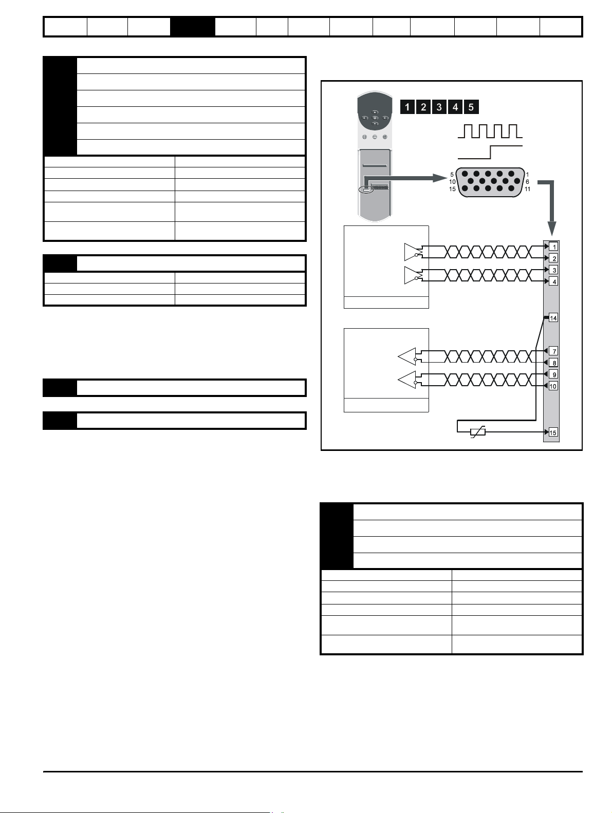
Safety
Information
Product
Information
Mechanical
Installation
Electrical
Installation
Getting
Star ted
Menu 0
Running
the motor
7 Phase channel U
8 Phase channel U\
9 Phase channel V
10 Phase channel V\
11 Phase channel W
12 Phase channel W\
Type EIA422 differential receivers
Maximum data rate 250kHz
Line termination components
Line loading 1 unit load
Absolute maximum applied voltage
relative to 0V
Absolute maximum applied differential
voltage
120
Ω
+15V to -10V
±25V
13 Encoder supply
Supply voltage +5.15V or +15V (selected by Pr 3.23)
Voltage tolerance ±2%
Nominal output current 300mA
The output voltage at terminal 13 is 5V when Pr 3.23 is set at 0 (default).
When Pr 3.23 is set at 1, the output voltage will become 15V. This could
damage encoders that require a 5V supply.
Termination resistors should be disabled by setting Pr 3.24 to 1 if the
encoder output is 15V.
14 0V common
Optimisation Macros
Advanced
Parameters
Technical
Data
Diagnostics
UL Listing
Information
4.10.2 Frequency and direction connections
Figure 4-18 Frequency and direction connections and alternative
motor-thermistor connections
Encoder connector
Female 15-way D-type
Frequency
reference
Direction
reference
Master
Frequency
reference
Direction
reference
15 Motor thermistor input
This terminal is connected internally to terminal 8 of the signal connector
Connect only one of these terminals to a motor thermistor. Analog input
3 must be in thermistor mode, Pr 7.15 = th.Sc (9) or th (10).
Slave
For encoder cable screening, see section 4-10 Feedback cable, twisted
pair on page 47.
Description of the frequency and direction connections
1 Frequency input FIN
2 Frequency input FIN\
3 Direction input DIN
4 Direction input DIN\
Type EIA422 differential receivers
Maximum data rate 250kHz
Line termination components
Line loading 1 unit load
Absolute maximum applied voltage
relative to 0V
Absolute maximum applied differential
voltage
Ω (switchable using Pr 3.24)
120
±15V
±25V
Unidrive User Guide 55
Issue Number: 9 www.controltechniques.com
Page 56

Safety
Information
Product
Information
Mechanical
Installation
Electrical
Installation
Getting
Star ted
Menu 0
Running
the motor
7 Frequency output FOUT
8 Frequency output FOUT\
9 Direction output DOUT
10 Direction output DOUT\
Type EIA422 differential receivers
Maximum data rate 250kHz
Line termination components
Absolute maximum applied voltage
relative to 0V
Absolute maximum applied differential
voltage
Ω
120
+15V to -10V
±25V
13 Encoder supply
Supply voltage +5.15V or +15V (selected by Pr 3.23)
Voltage tolerance ±2%
Nominal output current 300mA
The output voltage at terminal 13 is 5V when Pr 3.23 is set at 0 (default).
When Pr 3.23 is set at 1, the output voltage will become 15V. This could
damage encoders that require a 5V supply.
Termination resistors should be disabled by setting Pr 3.24 to 1 if the
encoder output is 15V.
14 0V common
Optimisation Macros
Advanced
Parameters
Technical
Data
Diagnostics
Figure 4-19 Location of the power module address switch
IN96
Phase-control board
DC-bus choke
IN95
Interface board
UL Listing
Information
15 Motor thermistor input
This terminal is connected internally to terminal 8 of the signal connector
Connect only one of these terminals to a motor thermistor. Analog input
3 must be in thermistor mode, Pr 7.15 = th.Sc (9) or th (10).
4.11 Configuring a Unidrive size 5 system
The following must be performed in order to configure a Unidrive size 5
system:
• Each power module must be given a unique address.
• The control module must be notified of the number of power
modules it is to control.
• The new settings must be saved in the control module software.
4.11.1 Configuring the power modules
To set the address on a power module, set the slide switch to the
required address number, see Figure 4-19 for the position of the switch.
Ensure that each power module in a multiple module system has its own
unique address number. See Table 4-6 for example configuration
settings.
56 Unidrive User Guide
www.controltechniques.com Issue Number: 9
Page 57

Safety
Information
Product
Information
Mechanical
Installation
Electrical
Installation
Getting
Star ted
Menu 0
Running
the motor
Optimisation Macros
Advanced
Parameters
Technical
Data
Diagnostics
UL Listing
Information
4.11.2 Configuring the control module
On the control module, set the configuration switches to correspond with
the addresses given to the power modules in the system. Move the
switch to the off position to set the switch. Ensure all remaining switches
are in the on position. See Table 4-6 for example configuration setting.
Figure 4-20 Setting the configuration switches in the control
module
4.11.3 Saving the configuration
When the drive is first powered-up, and the system contains more than
one power module (or the number of power modules has been
changed), the control module display will indicate as shown in Figure 4-
21.
Figure 4-21 Control module display
(The number displayed corresponds to the number power modules.)
A parameter save must be performed so that the drive will not trip next
time the drive is powered up. To perform a save refer to section
5.8 Saving parameters on page 61.
Table 4-6 Example configuration settings
Configuration switches
System
st
Power module 2nd Power module 3rd Power module
1
One control module can be used to control up to eight power modules.
Control module
Unidrive User Guide 57
Issue Number: 9 www.controltechniques.com
Page 58

Safety
)
Information
Product
Information
Mechanical
Installation
Electrical
Installation
Getting
Started
Menu 0
5 Getting Started
5.1 Understanding the display
The display consist of two horizontal rows of 7 segment displays.
The lower display shows the drive status or the current menu and
parameter number being viewed.
The upper display shows the parameter value or the specific trip type.
Figure 5-1 Keypad
Upper display
Lower display
Programming keys
Control keys
Running
the motor
Optimisation Macros
Advanced
Parameters
Pr value
Menu 5. Parameter 5
Trip type (UU = undervolts
Drive status = tripped
5.05
Technical
Data
Diagnostics
UL Listing
Information
5.2 Keypad operation
5.2.1 Control buttons
The keypad consists of:
1. Four arrow buttons
2. One mode button
3. Three control buttons
The arrow buttons are used to navigate the parameter structure and
change parameter values.
The mode button is used to change between the display modes –
parameter view, parameter edit, status.
The three control buttons are used to control the drive if keypad mode is
selected:
start (green)
stop (red)
forward / reverse (blue)
NOTE
The red ‘stop’ button is also used to reset the drive.
58 Unidrive User Guide
www.controltechniques.com Issue Number: 9
Page 59

Safety
S
Information
Product
Information
Mechanical
Installation
Figure 5-2 Display modes
tatus Mode
(display not flashing)
Electrical
Installation
Getting
Started
Menu 0
Running
the motor
Optimisation Macros
Status mode examples:
Advanced
Parameters
Technical
Data
Diagnostics
UL Listing
Information
To enter Parameter
Mode, press key
Parameter Mode
(display not flashing)
Use * keys
to select parameter for editing
To enter Edit Mode,
press key
Edit Mode
(upper line of display flashing)
Change parameter values
using keys.
To exit Edit Mode,
press key
8 seconds
timeout
When returning
to Parameter
Mode use the
keys to select
another parameter
to change, if
required
* can only be used to move between menus if standard
security has been opened. For further information, refer to section
5.10 Parameter security on page 62.
Healthy Status Trip Status Alarm Status
*
Do not change parameter values without careful
consideration; incorrect values may cause damage or a
WARNING
NOTE
When changing the values of parameters, make a note of the new
safety hazard.
**
values in case they need to be entered again.
NOTE
For new parameter-values to apply after the AC supply to the drive is
interrupted, new values must be saved. Refer to section 5.8 Saving
parameters on page 61.
5.3 Menu structure
The drive parameter structure consists of menus of parameters.
The drive initially powers up so that only menu 0 can be viewed. The up
and down arrow buttons are used to navigate between parameters and
once standard security has been cleared, the left and right buttons are
used to navigate between menus.
* can only be used to move between menus if standard
security has been opened. For further information, refer to section
5.10 Parameter security on page 62.
The menus and parameters roll over in both directions.
i.e. if the last parameter is displayed, a further press will cause the
display to rollover and show the first parameter.
When changing between menus the drive remembers which parameter
was last viewed in a particular menu and thus displays that parameter.
Unidrive User Guide 59
Issue Number: 9 www.controltechniques.com
Page 60

Safety
Information
Product
Information
Mechanical
Installation
Figure 5-3 Menu Structure
M
e
n
u
1
9
M
e
n
u
2
0
Menu 0
....xx.00....
2
0
.
0
1
2
0
.
0
2
2
0
.
0
3
2
0
.
0
4
2
0
.
0
5
0.01
0.02
0.03
0.04
0.05
Electrical
Installation
1
u
n
e
M
1
0
.
1
2
0
.
1
3
0
.
1
4
0
.
1
5
0
.
1
Getting
Started
Menu 0
Running
the motor
Optimisation Macros
Advanced
Parameters
Technical
Data
Diagnostics
UL Listing
Information
Figure 5-4 Menu 0 Cloning
Menu 2
5
Menu 4
4.07
2.21
150
Menu 1
1.14
0
2
u
n
e
M
Moves
between
parameters
Menu 0
0.04
0.05
0.06
5
0
150
2
0
.
4
6
2
0
2
0
2
0
2
0
NOTE
Menu 20 is only present when a large option module is present.
0.46
.
4
7
0.47
.
4
8
0.48
.
4
9
0.49
.
5
0
0.50
Moves between Menus
6
4
.
1
7
4
.
1
8
4
.
1
9
4
.
1
0
5
.
1
5.4 Advanced keypad functions
The following short-cuts can be used to speed up navigation of the drive
parameters and editing of parameters.
Key Press Parameter View Mode Parameter Edit Mode
+
+
jumps to xx.00
jumps to
00.yy
Sets value to 0
Jumps to LSB
5.5 Menu 0
Menu 0 is used to bring together various commonly used parameters for
basic easy set up of the drive.
Appropriate parameters are cloned from the advanced menus into menu
0 and thus exist in both locations.
5.6 Advanced menus
The advanced menus consist of groups or parameters appropriate to a
specific function or feature of the drive as follows:
Menu
number
Description
Commonly used basic set up parameters for quick / easy
0
programming
1 Speed references and limits
2 Ramps (accel / decel)
3 Speed feedback / frequency slaving
4 Current control
5 Machine control
6 Sequencing logic
7 Analog I/O
8 Digital I/O
9 Programmable logic
10 Status flags / trip log
11 Menu 0 customisation / drive specific ratings
12 Programmable thresholds
13 Digital lock / orientation
14 Programmable PID function
15 Regen
16 Small option module set up
17 Large option module set up
18 Application menu 1
19 Application menu 2
20 Large option module set up
60 Unidrive User Guide
www.controltechniques.com Issue Number: 9
Page 61

Safety
Information
Product
Information
Mechanical
Installation
Electrical
Installation
Getting
Started
Menu 0
Running
the motor
Optimisation Macros
Advanced
Parameters
Technical
Data
Diagnostics
UL Listing
Information
5.6.1 Display messages
Status indications
The following tables indicate the various possible mnemonics which can
be displayed by the drive and their meaning.
Trip types are not listed here but can be found in Chapter
12 Diagnostics if required.
Lower
display
Conditions
Act Regeneration mode active
Regen mode> The Regen drive is enabled and
synchronised to the supply.
ACUU AC Supply loss
The drive has detected that the AC supply has been
lost and is attempting to maintain the
DC bus voltage
by decelerating the motor.
dc DC applied to the motor
The drive is applying
DC injection braking.
dEC Decelerating
The drive is decelerating the motor.
inh
Inhibit
The drive is inhibited and cannot be run.
Drive enable signal not applied to terminal 30 or Pr
6.15 is set to 0.
POS Positioning
The drive is positioning/orientating the motor shaft.
rdY Ready
The drive is ready to be run.
run
Running
The drive is running.
SCAn Scanning
OL> The drive is searching for the motor frequency
when synchronising to a spinning motor.
Regen> The drive is enabled and is synchronising to
the line.
StoP Stop or holding zero speed
The drive is holding the motor at zero speed.
Regen> The drive is enabled but the AC voltage is too
low, or DC Bus voltage still rising or falling.
triP Trip condition
The drive has tripped and is no longer controlling the
motor. The trip code appears on the upper display.
Alarm indications
Lower
display
Air Control PCB ambient temperature near maximum limit
The ambient temperature around the control PCB has reached 90°C
(194°F) and the drive will trip OA if the temperature continues to rise
(see the OA trip).
br.rS Braking resistor overload
The braking-resistor [I x t] accumulator in the drive has reached 75%
of the value at which the drive will be tripped.
hot
Heatsink temperature near maximum limit
The drive heatsink has reached 90°C (194°F) and the drive will trip
Oh2 if the temperature continues to rise (see the Oh2 trip).
OVLd Motor overload
The motor [I x t] accumulator in the drive has reached 75% of the value
at which the drive will be tripped.
Conditions
Drive output
stage
Enabled
Enabled
Enabled
Enabled
Disabled
Enabled
Disabled
Enabled
Enabled
Enabled
Disabled
5.7 Changing the operating mode
Changing the operating mode returns all parameters to their default
value, including the motor parameters.
Procedure
Use the following procedure only if a different operating mode is
required:
1. Enter either of the following values in Pr 0.00, as appropriate:
1253 (Europe, 50Hz AC supply frequency)
1254 (USA, 60Hz AC supply frequency)
2. Change the setting of Pr 0.48 as follows:
Pr 0.48 setting Operating mode
0 Open-loop
1
2
3
The figures in the second column apply when serial communications are
used.
3. Press or momentarily close the RESET contact.
The new setting takes effect and all the parameters revert to the
appropriate default values for the new mode.
Closed-loop Vector
Closed-loop Servo
For operation in this mode, refer to
the Unidrive Regen Installation
Guide
5.8 Saving parameters
Procedure
Enter 1000 in Pr xx.00
Press the red reset button or toggle the reset digital input
(ensure Pr xx.00 returns to 0)
5.9 Defaulting the drive
Procedure
Enter 1233 (EUR 50 Hz settings) or 1244 (USA 60 Hz settings) in
Pr xx.00
Press the red reset button or toggle the reset digital input (ensure
Pr xx.00 returns to 0)
Unidrive User Guide 61
Issue Number: 9 www.controltechniques.com
Page 62

Safety
S
Information
Product
Information
Mechanical
Installation
Electrical
Installation
Getting
Started
Menu 0
Running
the motor
Optimisation Macros
Advanced
Parameters
Technical
Data
Diagnostics
UL Listing
Information
5.10 Parameter security
There are two independent levels of security that can be enabled /
disabled in the Unidrive. This gives four possible combinations of
security settings as shown in the table below:
Standard
security
Open Open RW RW
Open Closed RO RO
Closed Open RW Not visible
Closed Closed RO Not visible
User security Menu 0 status
RW = Read / write access
RO = Read only access
The default settings of the drive are standard security closed and user
security open, i.e. read / write access to Menu 0 with the advanced
menus (i.e. menus 1 to 20) not visible.
5.10.1 Standard security
Standard security prevents read and write access to the advanced menu
parameters.
tandard security closed
Pr 0.00
Pr 0.01
Pr 0.02
Pr 0.03
Pr 0.49
Pr 0.50
Pr 1.00
Pr 1.01
Pr 1.02
Pr 1.03
Pr 1.49
Pr 1.50
Standard security open
- Menu 0 only visible
............
............
............
............
............
............
............
............
- All parameters visible
Advanced menus status
(i.e menus 1 to 20)
Pr 19.00
Pr 19.01
Pr 19.02
Pr 19.03
Pr 19.49
Pr 19.50
Pr 20.00
Pr 20.01
Pr 20.02
Pr 20.03
Pr 20.49
Pr 20.50
Disabling standard security
Set parameter 0.34 to 0 and press the button.
NOTE
This action also disables user security if it has been enabled.
Enabling standard security
Set parameter 0.34 to 149 and press the button.
5.10.2 User security
User security prevents write access to all parameters except xx.00.
User security open
Pr 0.00
Pr 0.01
Pr 0.02
Pr 0.03
Pr 0.49
Pr 0.50
User security closed
except Pr
xx.00
Pr 0.00
Pr 0.01
Pr 0.02
Pr 0.03
Pr 0.49
Pr 0.50
- All parameters: Read / Write access
Pr 1.00
Pr 1.01
Pr 1.02
Pr 1.03
............
............
............
............
Pr 19.00
Pr 19.01
Pr 19.02
Pr 19.03
............
............
Pr 1.49
Pr 1.50
............
............
Pr 19.49
Pr 19.50
- All parameters: Read Only access,
Pr 1.00
Pr 1.01
Pr 1.02
Pr 1.03
............
............
............
............
Pr 19.00
Pr 19.01
Pr 19.02
Pr 19.03
............
............
Pr 1.49
Pr 1.50
............
............
Pr 19.49
Pr 19.50
Pr 20.00
Pr 20.01
Pr 20.02
Pr 20.03
Pr 20.49
Pr 20.50
Pr 20.00
Pr 20.01
Pr 20.02
Pr 20.03
Pr 20.49
Pr 20.50
Setting user security
Enter a value between 1 and 256 (except 149) in parameter 0.34. Once
the button has been pressed the value reverts to 149 to hide the
security code which has been set.
Pr 0.00
Pr 0.01
Pr 0.02
Pr 0.03
Pr 0.49
Pr 0.50
Opening standard security
Set parameter xx.00 to 149 and press the button.
Closing security
Set parameter xx.00 to 2000 and press the button or cycle the
power to the drive.
NOTE
This action also closes user security if it has been enabled.
Pr 1.00
Pr 1.01
Pr 1.02
Pr 1.03
Pr 1.49
Pr 1.50
............
............
............
............
............
............
............
............
Pr 19.00
Pr 19.01
Pr 19.02
Pr 19.03
Pr 19.49
Pr 19.50
Pr 20.00
Pr 20.01
Pr 20.02
Pr 20.03
Pr 20.49
Pr 20.50
Save parameters by setting parameter xx.00 to 1000 and press the
button.
Opening user security
Enter the security code into parameter xx.00.
Closing user security
Set parameter xx.00 to 2000 and press the mode button or cycle the
power to the drive.
NOTE
This action also closes standard security if it has been enabled.
Disabling user security
Set parameter 0.34 to 0 and press the button to disable both user
and standard security
Set parameter 0.34 to 149 and press the button to disable user,
but set standard, security.
62 Unidrive User Guide
www.controltechniques.com Issue Number: 9
Page 63

Safety
(
)
(
)
Information
Product
Information
Mechanical
Installation
Electrical
Installation
Getting
Started
Menu 0
Running
the motor
5.11 Serial Communications
5.11.1 Introduction
The Unidrive has an optional serial communications interface in the form
of the UD71 serial communications module. This module has a fully
optically isolated 4 wire or 2 wire EIA485 interface and an EIA232
interface. (The EIA232 interface should be used for commissioning
purposes only.)
5.11.2 Serial communications module hardware connections
See Figure 3-5 on page 15 for information regarding installing the UD71
serial communications large option module in the drive.
Figure 5-5 Location of communication interfaces
AB
DC
EIA485 Interface
male 9 pin D-type
Table 5-1 Serial communications connections
Pin
EIA485 Interface EIA232 Interface
4 wire mode 2 wire mode UD71 Host PC
10V 0V CD CD
2 TX\ TX\ RX\* TXD** RXD**
3 RX\ TX\ RX\* RXD** TXD**
4 Not connected Not connected DTR DTR
5 Not connected Not connected 0V** 0V**
6 TX TX RX* DSR DSR
7RX TX RX* RTS RTS
8 Not connected Not connected CTS CTS
9 Not connected Not connected NC RI
* Pins 2 and 3, and pins 6 and 7 must be connected together in 2 wire
EIA485 mode.
** Depending on the host software being used, it may only be necessary
to connect pins 2, 3 and 5 when using the EIA232 interface.
When connecting EIA232 interface on the UD71 serial communications
module to the 9 pin serial port on a PC, a 9 pin male D-type to 9 pin
female D-type serial extension cable can be used.
EIA232 Interface
Female 9 pin D-type
Optimisation Macros
Advanced
Parameters
Technical
Data
Diagnostics
UL Listing
Information
11.24 Serial comms. mode
RW Txt P
ANSI 2 (0), ANSI 4 (1), OUtPUt (2),
Ú
INPUt (4)
Ö
ANSI 4 (1)
This is the mode of operation of the serial port.
ANSI 2 (0) Standard 2 wire EIA485 using ANSI protocol
ANSI 4 (1) Standard 4 wire EIA485 using ANSI protocol
OUtPUt (2) Output variable defined by Pr 11. 27
INPUt (3) Input variable defined by Pr 11 .27
OUtPUt (2) and INPUt (3) are used to transfer a variable parameter from
one drive to another. See the Unidrive Advanced User Guide for more
information.
11.25 Serial comms. baud rate
RW Txt P
4800 (0), 9600 (1), 19200 (2),
Ú
2400 (3)
Ö
4800 (0)
Used in 2 or 4 wire ANSI modes to select the communications port baud
rate.
4800 (0) 4800 baud
9600 (1) 9600 baud
19200 (2) 19200 baud
2400 (3) 2400 baud
11.26 Serial comms. two-wire mode delay
RW Uni P
Ú
0 to 255 ms
Ö
0
If 2 wire EIA485 communications is being used then a delay is required
between the drive receiving data and then responding to allow the
device that sent the request to changes its buffers from transmit to
receive.
5.11.3 Serial communications set-up parameters
The following parameters need to be set according to the system
requirements.
11.23 Serial comms. address
RW Uni P
Ú
0.0 to 9.9
Ö
Defines the unique address for the drive. Any number in the permitted
range 0.0 to 9.9 which has a zero in it, should not be used as these are
used to address groups of drives.
Unidrive User Guide 63
Issue Number: 9 www.controltechniques.com
1.1
Page 64

Safety
Information
Product
Information
Mechanical
Installation
Electrical
Installation
Getting
Star ted
Menu 0
Running
the motor
Optimisation Macros
Advanced
Parameters
Technical
Data
Diagnostics
UL Listing
Information
6 Menu 0
6.1 Single line descriptions
6.1.1 Unidrive (All variants excluding Unidrive VTC)
Ú) Default(Ö)
Parameter
Operating mode, Macro selection,
0.00
Configuration, Saving
OL> Minimum frequency {1.07} 0 to [Pr 0.02]Hz 0 RW Uni
0.01
CL> Minimum speed {
OL> Maximum frequency {1.06} 0 to 1,000.0Hz
0.02
CL> Maximum speed {
0.03 Acceleration rate {2.11} 0 to 3,200.0 s/100Hz
0.04 Deceleration rate {2.21} 0 to 3,200.0 s/100Hz
0.05 Reference selector {1.14} 0 to 5
0.06 Current limit {4.07}
OL> Voltage mode selector {5.14}
0.07
CL> Speed control P gain {
OL> Voltage boost {5.15} 0.0 to 25.0 % 3.0 RW Uni
0.08
CL> Speed control I gain {
OL> Dynamic V/f select {5.13}0 or 1 0 RW Bit
0.09
CL> Speed control D gain {
OL> Estimated motor speed {5.04} ±6,000 rpm RO Bi
0.10
CL>Motor speed {
0.11 Pre-ramp reference {1.03} ±1,000.0 Hz ±30,000 rpm RO Bi
0.12 Post-ramp reference {2.01} ±1,000.0 Hz ±30,000 rpm RO Bi
0.13 Motor active-current {4.02}
0.14 Jog reference {1.05} 0 to 400.0 Hz 0 to 4,000.0 rpm 1.5 50 RW Uni
0.15 Ramp mode selector {2.04} Stnd.Hd (0), FASt (1), Stnd.Ct (2) Stnd.Ct (2) RW Txt
0.16 Stop mode selector {6.01}
0.17 Torque mode select {4.11} 0 to 1 0 to 4 0 RW Uni
0.18 S-Ramp enable {2.06}0 or 1 0RWBit
0.19 S-Ramp da / dt limit {2.07}
0.20 Skip frequency/speed 1 {1.29} 0.0 to 1,000.0 Hz 0 to 30,000 rpm 0 RW Uni
0.21 Skip band 1 {1.30} 0.0 to 5.0 Hz 0 to 50 rpm 0.5 5 RW Uni
0.22 Skip frequency/speed 2 {1.31} 0.0 to 1,000.0 Hz 0 to 30,000 rpm 0 RW Uni
0.23 Skip band 2 {1.32} 0.0 to 5.0 Hz 0 to 50 rpm 0.5 5 RW Uni
0.24 Analog input 1 mode selector {7.06}
0.25 Analog input 2 mode selector {7.11}(as Pr 0.24) VOLt (0) RW Txt R
0.26 Analog input 2 destination {7.14}Pr 0.00 to Pr 20.50 Pr 1.37 RW Uni R P
EUR> Positive logic select {8.27}0 or 1 0RWBitRP
0.27
USA> Sequencing mode selector
EUR> Current control P gain {4.13} 0 to 30,000 20 150 30 RW Uni
0.28
USA> Frequency/speed demand
EUR> Current control I gain {4.14} 0 to 30,000 40 2,000 1,200 RW Uni
0.29
USA> Terminal-29 destination
parameter
0.30 Forward / reverse key enable {6.13}0 or 1 0RWBit
0.31 Macro number {11.37} 0 to 8 RO Uni
0.32 Serial comms mode {11.24} ANSI 2 (0), ANSI 4 (1), OUtPUt (2), INPUt (3) ANSI 4 (1) RW Txt R P
0.33 Drive rated current (FLC) {11.3 2} 2.10 to 1920 A RO Uni P
0.34 User security code {11. 30} 0 to 255 149 RW Uni S P
0.35 Keypad reference {1.17}± [Pr 0.02] Hz ± [Pr 0.02] rpm RO Bi S P
0.36 Serial comms. baud rate {11. 25} 4,800 (0), 9,600 (1), 19,200 (2) baud 4,800 (0) RW Txt P
0.37 Serial comms. address {11.23} 0.0 to 9.9 Group.Unit 1.1 RW Uni P
0.38 Initial parameter displayed {11. 22}Pr 0.00 to Pr 0.50 Pr 0.10 RW Uni P
1.07} 0 to [Pr 0.02]rpm 0RWUni
1.06} 0 to 30,000rpm
3.10} 0 to 32,000 % 200 RW Uni
3.11} 0 to 32,000 100 RW Uni
3.12} 0 to 32,000 0RWUni
3.02} ±30,000 rpm RO Bi
(6.04) 0 to 4 4 RO Uni P
(1.01) ±1,000Hz ±30,000 rpm RO Bi
8.23}Pr 0.00 to Pr 20.50 Pr 1.41 RW Uni R P
{
OL CL OL VT SV
Ur_S (0), Ur_l (1),
Ur (2), Fd (3)
COASt (0), rP (1),
rP-dcI (2), dcI (3),
td.dcI (4)
0 to 3,000.0 s
VOLt (0), 0 - 20 (1), 20 - 0 (2), 4 - 20.tr (3),
20 - 4.tr (4), 4 - 20.Lo (5), 20 - 4.Lo (6),
Range(
0 to 9,999 0 RW Uni R
EUR> 50
USA> 60
EUR>
VT> 0 to 3,200 s/1000rpm
SV> 0 to 32.000
s/1000rpm
VT> 0 to 32.000 s/
1000rpm
SV> 0 to 32,000 s/
1000rpm
%
0 to I
max
A
±I
max
COASt (0), rP (1),
no.rP (2), rP-POS (3)
2
/100 Hz 0 to 30,000 s2/1000 rpm
4 - 20.Pr (7), 20 - 4.Pr (8)
1,500
USA>
1,800
5 2 0.2 RW Uni
10 2 0.2 RW Uni
EUR> 0
USA> 4
150 175 RW Uni
Ur_l (1) RW Uni P
rP (1) no.rP (2) RW Txt
3.1 1.5 0.03 RW Uni
VOLt (0) RW Txt R
3000 RW Uni
0RWUni
Typ e
RW Uni
RO Bi
64 Unidrive User Guide
www.controltechniques.com Issue Number: 9
Page 65

Safety
Information
0.39 Synchronise to a spinning motor {6.09}0 or 1 01RWBit
0.40 Autotune
0.41 PWM switching frequency {5.18}
0.42 Motor - no. of poles {5.11} 2 POLE (0) to 32 POLE (15) 4 POLE (1) 6 POLE (3) RW Txt P
0.43 Motor - rated power factor {5.10} 0.000 to 1.000
0.44 Motor - rated voltage {5.09}
0.45 Motor - rated speed {5.08} 0 to 6,000 rpm 0 to 30,000 rpm 0
0.46 Motor - rated current {5.07} 0 to FLC A FLC RW Uni
0.47 Motor - rated frequency {5.06} 0 to 1,000.0 Hz
0.48 Drive operating mode selector {11. 31}
0.49 Security status 0 to 1,000 1 RO Uni P
0.50 Software version number {11.29} 1.00 to 99.99 RO Uni P
Product
Information
Parameter
Mechanical
Installation
Electrical
Installation
{
5.12}
(3.25)
Getting
Star ted
Menu 0
OL CL OL VT SV
3 kHz (0), 4.5 kHz (1), 6 kHz (2), 9 kHz (3),
OPENLP (0), CL.VECT (1),
Running
the motor
Range(
0 or 1 0 RW Bit P
12 kHz (4)
200V drive: 0 to 240 V
400V drive: 0 to 480 V
SErVO (2), rEGEN (3)
Optimisation Macros
Ú)Default(Ö)
VT> 0.000 to 1.000
SV> 1
VT> 0 to 1,000.0 Hz
SV> 0
Advanced
Parameters
0.92 1 RW Uni S P
200V drive: 220
400V drive: EUR> 400
USA> 460
EUR> 50
USA> 60
OPENLP
(0)
Technical
Data
3 (0)* RW Txt
EUR> 1450
USA> 1770
CL.VECT
(1)
Diagnostics
0RWUni
RW Uni
0RWUni
SErVO
(2)
RW Txt R P
UL Listing
Information
Typ e
* Pr 0.41 PWM switching frequency has a default setting of 9kHz in
Unidrive LFT
Key:
RO Read Only parameter
RW Read / Write parameter
Uni Unipolar variable parameter R Reset required for new value to take effect
Bi Bipolar variable parameter S New parameter-value saved at power-down
Txt Text variable parameter P Protected; forbidden as destination parameter
Bit Bit parameter FLC Full-load current (max. continuous)
Types of current range
FLC Full load current of the drive (maximum continuous output
o
current up to 40
C ambient temperature). Displayed in Pr 11.32
{0.33}.
I
A Maximum overload output current of the drive up to 40oC
MAX
ambient temperature, derived as follows:
Size 1 to 4: OL> 150% x FLC
CL> 175% x FLC
Size 5: 150% x FLC
I
% See section 8.2 Current limits on page 98 for the definition of
MAX
NOTE
Where a parameter is represented by a text value, the value in brackets
I
MAX
%.
in the range column is the setting used for serial communications.
Operation mode abbreviations:
OL> Open loop
CL> Closed loop (which incorporates closed loop vector and
servo mode)
VT> Closed loop vector mode
SV> Servo
Unidrive User Guide 65
Issue Number: 9 www.controltechniques.com
Page 66
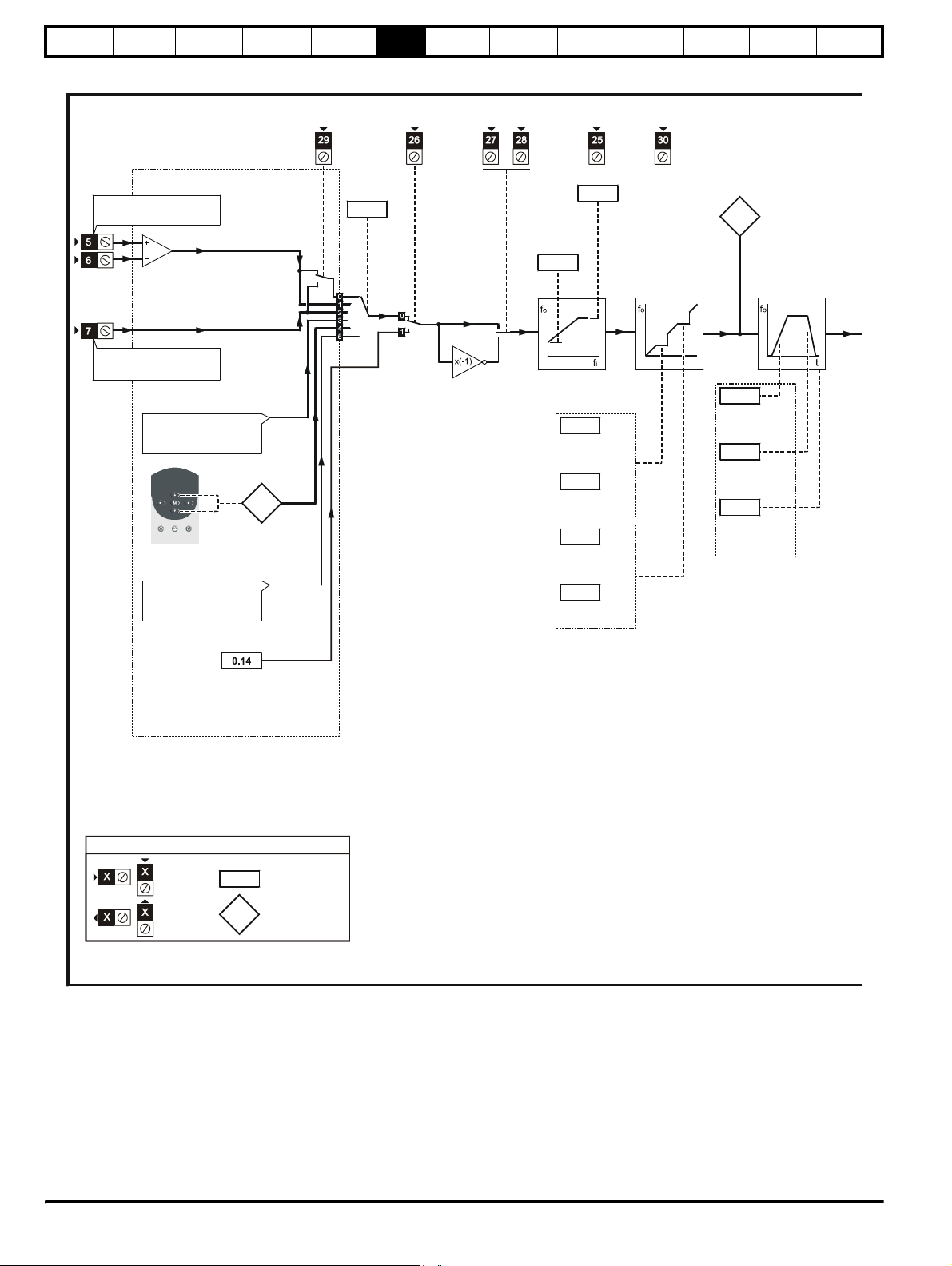
Safety
Information
Product
Information
Mechanical
Installation
Electrical
Installation
Getting
Star ted
Menu 0
Figure 6-1 Unidrive menu 0 logic diagram (excluding VTC)
Running
the motor
Optimisation Macros
Advanced
Parameters
Technical
Data
Diagnostics
UL Listing
Information
Reference selection
Frequency/speed ref. 1
(remote)
6
6
Frequency/speed ref. 2
(local)
Preset references
(see the )Unidrive
Advanced User Guide
Precision reference
(not used with Menu 0)
0.35
Keypad
reference
LOCAL /
REMOTE
Reference
selector
0.05
JOG
SELECT
RUN
FORWARD
RUN
REVERSE
Minimum
frequency/
speed clamp
RESET
0.02
0.01
0.20
Skip frequency/
speed 1
0.21
Skip freq./speed
band 1
0.22
Skip frequency/
speed 2
0.23
Skip freq./speed
band 2
OL> EXTERNAL TRIP
CL> DRIVE ENABLE
Maximum
frequency/speed
clamp
Skip
frequencies/
speeds
Pre-ramp
reference
0.11
0.03
Acceleration
rate
0.04
Deceleration
rate
0.15
Ramp mode
selector
Ramps
Jog
reference
Key
Input
terminals
Output
terminals
The parameters are all shown in their default settings
0.XX
0.XX
Read-write (RW)
parameter
Read-only (RO)
parameter
66 Unidrive User Guide
www.controltechniques.com Issue Number: 9
Page 67

Safety
Information
Product
Information
Mechanical
Installation
Electrical
Installation
Getting
Star ted
Menu 0
Running
the motor
Optimisation Macros
Advanced
Parameters
Technical
Data
Diagnostics
UL Listing
Information
S-ramp
S-ramp
enable
0.18
0.19
S-ramp
da/dt limit
Post-ramp
reference
0.12
THERMISTOR
CL> Speed-loop PID gains
Speed-loop
0.07
proportional
gain
Speed-loop
0.08
integral gain
Speed-loop
0.09
derivative
gain
OL> FREQUENCY
CL> SPEED
OL> Motor-voltage control
0.10
Estimated
motor
speed
TORQUE
Motor control
0.06
0.16
0.39
Motor parameters
0.42 ~ 0.47
No. of poles
Power factor
Rated voltage
Rated speed
Rated current
Rated frequency
0.07
Voltage mode
selector
0.08
Boost voltage
0.09
Dynamic V/f
select
OL> AT SPEED
CL> AT ZERO SPEED
Current
limit
Stop mode
selector
Drive
_
+
Motor speed
0.10
15 way sub-D
connector
0.13
Motor
active-current
Power stage
0.41
PWM switching
frequency
_
+
Resistor
optional
Unidrive User Guide 67
Issue Number: 9 www.controltechniques.com
Page 68

Safety
Information
Product
Information
Mechanical
Installation
Electrical
Installation
Getting
Star ted
Menu 0
Running
the motor
Optimisation Macros
Advanced
Parameters
Technical
Data
Diagnostics
UL Listing
Information
6.1.2 Unidrive VTC
Parameter
Operating mode, Macro selection,
0.00
Configuration, Saving
Range(
Ú) Default(Ö)
0 to 9,999 0 RW Uni R
0.01 Minimum frequency {1.07} 0 to [Pr 0.02]Hz 0 RW Uni
0.02 Maximum frequency {1.06} 0 to 250.0Hz EUR> 50, USA> 60 RW Uni
0.03 Acceleration rate {2.11} 0 to 3,200.0 s/100Hz 60 RW Uni
0.04 Deceleration rate {2.21} 0 to 3,200.0 s/100Hz 60 RW Uni
0.05 Reference selector {1.14} 0 to 5 0 RW Uni
0.06 Current limit {4.07}
0.07 Voltage mode selector {5.14}
0 to I
max
Ur_S (0), Ur_l (1),
Ur (2), Fd (3)
120 RW Uni
Fd (3) RW Txt P
%
0.08 Voltage boost {5.15} 0.0 to 15.0 % 3.0 RW Uni
0.09 Dynamic V/f select {5.13}0 or 1 0RWBit
0.10 Estimated motor speed {5.04} ±6,000 rpm RO Bi P
0.11 Pre-ramp reference {1.03} ±1,000.0 Hz RO Bi P
0.12 Post-ramp reference {2.01} ±1,000.0 Hz RO Bi P
A
0.13 Motor active-current {4.02}
±I
max
0.14 Total motor current {4.01} 0 to 400.0 Hz RO Uni P
0.15 Ramp mode selector {2.04} Stnd.Hd (0), FASt (1), Stnd.Ct (2) Stnd.Ct (2) RW Txt
0.16 Stop mode selector {6.01} COASt (0), rP (1), rP-dcI (2), dcI (3), td.dcI (4) rP (1) RW Txt
0.17 Total motor power {5.03}
±P
MAX
0.18 S-Ramp enable {2.06}0 or 1 0RWBit
0.19 S-Ramp da / dt limit {2.07}
0 to 3,000.0 s
2
/100 Hz
450.0 RW Uni
0.20 Skip frequency 1 {1.29} 0.0 to 1,000.0 Hz 0 RW Uni
0.21 Skip band 1 {1.30} 0.0 to 5.0 Hz 0.5 RW Uni
0.22 Drive rated current (FLC) {11.3 2} 2.10 to 202 A RO Uni P
0.23 Analog input 1 mode selector {7.06}
VOLt (0), 0 - 20 (1), 20 - 0 (2), 4 - 20.tr (3),
20 - 4.tr (4), 4 - 20.Lo (5), 20 - 4.Lo (6),
VOLt (0) RW Txt R
4 - 20.Pr (7), 20 - 4.Pr (8)
0.24 Preset frequency 1 {1.21} ±1,000.0 Hz 0 RW Bi
0.25 Preset frequency 2 {1.22} ±1,000.0 Hz 0 RW Bi
0.26 Standard ramp voltage {2.08}
200V drive: 0 to 400 V
400V drive: 0 to 800 V
200V drive: 375
400V drive: EUR> 750, USA> 775
0.27 Current control P gain {4.13} 0 to 30,000 20 RW Uni
0.28 Current control I gain {4.14} 0 to 30,000 20 RW Uni
0.29 DC bus voltage {5.05}
200V drive: 0 to 415 V
400V drive: 0 to 830 V
0.30 Last trip {10.20} 0 to 200 RO Txt S P
0.31 Macro number {11 .37} 0, 1, 2, 3, 5 0 RO Uni
0.32 Number of auto-reset attempts {10.34} 0 to 5 0 RW Uni
0.33 Auto-reset time delay {10.35} 0.0 to 25.0 s 1.0 RW Uni
0.34 User security code {11. 30} 0 to 255 149 RW Uni S P
0.35 Serial comms. mode {11. 24} ANSI 2 (0), ANSI 4 (1), OUtPUt (2), INPUt (3) ANSI 4 (1) RW Txt R P
0.36 Serial comms. baud rate {11. 25} 4,800 (0), 9,600 (1), 19,200 (2) baud EUR> 4,800, USA> 9,600 RW Txt P
0.37 Serial comms. address {11.23} 0.0 to 9.9 Group.Unit 1.1 RW Uni P
0.38 Initial parameter displayed {11. 22}Pr 0.00 to Pr 0.50 EUR> Pr 0.10, USA> Pr 0.12 RW Uni P
0.39 Synchronise to a spinning motor {6.09}0 or 1 0RWBit
0.40 Autotune {5.12}0 or 1 0RWBitP
0.41 PWM switching frequency {5.18}
3 (0), 4.5 (1), 6 (2), 9 (3),
12 (4) kHz
3 (0) RW Txt
0.42 Motor - no. of poles {5.11} 2 POLE (0) to 32 POLE (15) 4 POLE (1) RW Txt P
0.43 Motor - rated power factor {5.10} 0.000 to 1.000 0.92 RW Uni S P
0.44 Motor - rated voltage {5.09}
200V drive: 0 to 240 V
400V drive: 0 to 480 V
200V drive: 220
400V drive: EUR> 400,
USA> 460
0RWUni
0.45 Motor - rated speed {5.08} 0 to 6,000 rpm 0 RW Uni
0.46 Motor - rated current {5.07} 0 to FLC A FLC RW Uni
0.47 Motor - rated frequency {5.06} 0 to 1,000.0 Hz EUR> 50, USA> 60 RW Uni
0.48 Overload accumulator {4.19} 0 to 100 % RO Uni P
0.49 Security status 0 or 1 1 RO Bit
0.50 Software version number {11.2 9} 1.00 to 99.99 RO Uni P
Typ e
RO Bi P
RO Bi P
RW Uni
RO Uni P
Key:
RO Read Only parameter
RW Read / Write parameter
Uni Unipolar variable parameter R Reset required for new value to take effect
Bi Bipolar variable parameter S New parameter-value saved at power-down
Txt Text variable parameter P Protected; forbidden as destination parameter
Bit Bit parameter FLC Full-load current (max. continuous)
68 Unidrive User Guide
www.controltechniques.com Issue Number: 9
Page 69

Safety
Information
Product
Information
Mechanical
Installation
Electrical
Installation
Getting
Star ted
Menu 0
Types of current range
FLC Full load current of the drive (maximum continuous output
o
current up to 40
C ambient temperature). Displayed in Pr 11.32
{0.22}.
I
A Maximum overload output current of the drive up to 40oC
MAX
ambient temperature, derived as follows:
120% x FLC
% See section 8.2 Current limits on page 98 for the definition of
I
MAX
P
MAX
I
MAX
%.
3I
×
MAX
Pr 5.09
------------------
×=
1000
Running
the motor
Optimisation Macros
Advanced
Parameters
Technical
Data
Diagnostics
UL Listing
Information
NOTE
Where a parameter is represented by a text value, the value in brackets
in the range column is the setting used for serial communications.
Unidrive User Guide 69
Issue Number: 9 www.controltechniques.com
Page 70

Safety
Information
Product
Information
Mechanical
Installation
Electrical
Installation
Getting
Star ted
Figure 6-2 Unidrive VTC menu 0 logic diagram
Menu 0
Running
the motor
Optimisation Macros
Advanced
Parameters
Technical
Data
Diagnostics
UL Listing
Information
Reference selection
Frequency/speed ref. 1
6
6
Frequency/speed ref. 2
All preset references
(not used with Menu 0)
Preset
reference 1
Preset
reference 2
ANALOG INPUT/
PRESET
SELECT
Reference
selector
0.05
PRESET REF
SELECT
RUN
FORWARD
RUN
REVERSE
Minimum
frequency
clamp
RESET
0.01
0.20
Skip frequency1
0.21
Skip frequency
band 1
0.02
EXTERNAL
TRIP
Maximum
frequency/speed
clamp
Skip band
Pre-ramp
reference
Acceleration
rate
Deceleration
rate
Ramp mode
selector
0.11
Ramps
0.03
0.04
0.15
Precision reference
(not used with Menu 0)
Key
Input
terminals
Output
terminals
The parameters are all shown in their default settings
0.XX
0.XX
Read-write (RW)
parameter
Read-only (RO)
parameter
70 Unidrive User Guide
www.controltechniques.com Issue Number: 9
Page 71

Safety
_+_
Information
Product
Information
Mechanical
Installation
Electrical
Installation
Getting
Star ted
Menu 0
Running
the motor
Optimisation Macros
Advanced
Parameters
Technical
Data
Diagnostics
UL Listing
Information
S-ramp
S-ramp
enable
0.18
0.19
S-ramp
da/dt limit
Post-ramp
reference
0.12
THERMISTOR
FREQUENCY
TOTAL MOTOR
CURRENT
Current
0.06
limit
Stop mode
0.16
selector
0.39
No. of poles
Power factor
Rated voltage
Rated speed
Rated current
Rated frequency
Motor-voltage control
0.07
0.08
0.09
0.10
EUR> AT SPEED
USA> DRIVE RUNNING
Motor control
0.26
0.27
0.28
Motor parameters
0.42 to 0.47
Voltage mode
selector
Boost voltage
Dynamic V/f
select
Estimated
motor speed
Standard
ramp voltage
Current-loop
proportional
gain
Drive
+
Power stage
PWM switching
0.41
frequency
DC bus
0.29
voltage
0.13
Motor
active-current
0.14
Tota l m o t o r
current
0.17
Tota l m o t or
power
accumulator
0.48
Overload
Resistor
optional
Unidrive User Guide 71
Issue Number: 9 www.controltechniques.com
Page 72

Safety
Information
Product
Information
Mechanical
Installation
Electrical
Installation
Getting
Star ted
Menu 0
Running
the motor
6.2 Menu 0 full descriptions
6.2.1 Menu 0 configuration
0.00
RW Uni R
Ú
Value Function
1000 Save new parameter-values
1233
1244
1253
1254
2001 Macro 1 Easy mode
2002 Macro 2 Motorized potentiometer
2003 Macro 3 Preset speeds
2004 Macro 4 Torque control
2005 Macro 5 PID control
2006 Macro 6 Axis-limit control
2007 Macro 7 Brake control
2008 Macro 8 Digital lock / shaft orientation
Press after setting Pr 0.00 at the required value.
6.2.2 Speed limits
0.01 {1.07}
RW Uni
OL
Ú
CL
Ú
(When the drive is jogging, [Pr 0.01] has no effect.)
Open-loop
Set 0.01 at the required minimum output frequency of the drive for both
directions of rotation. The drive runs at the minimum frequency when the
frequency reference is zero.
[Pr 0.01] is a nominal value; slip compensation may cause the actual
frequency to be higher.
Closed-loop
Set Pr 0.01 at the required minimum motor speed for both directions of
rotation. The motor runs at the minimum speed when the speed
reference is zero.
0.02 {1.06}
RW Uni
OL
Ú
CL
Ú
* This parameter has a maximum range of 250Hz in Unidrive VTC.
(The drive has additional over-speed protection.)
Operating mode, Macro selection, Configuration,
Saving
0 to 9,999
Restore parameters to their default values for 50Hz
frequency (Europe)
Restore parameters to their default values for 60Hz
frequency (USA)
Enable the operating mode of the drive to be changed and restore
parameters to their default values for 50Hz
(Europe)
Enable the operating mode of the drive to be changed and restore
parameters to their default values for 60Hz
Ö
0
AC supply
AC supply
AC supply frequency
AC supply frequency (USA)
OL> Minimum frequency
CL> Minimum speed
0 to [Pr 0.02]Hz
0 to [Pr 0.02]rpm
Ö
Ö
0
0
OL> Maximum frequency
CL> Maximum speed
0 to 1,000Hz*
VT> 0 to 30,000rpm
SV> 0 to 30,000rpm 3,000
Ö
Ö
EUR> 50
USA> 60
EUR> 1,500
USA> 1,800
Optimisation Macros
Advanced
Parameters
Technical
Data
Diagnostics
UL Listing
Information
Open-loop
Set Pr 0.02 at the required maximum output frequency for both
directions of rotation. The frequency reference cannot cause the drive to
run at a frequency higher than [Pr 0.02].
[Pr 0.02] is a nominal value; slip compensation may cause the actual
frequency to be higher.
Closed-loop
Set Pr 0.02 at the required maximum motor speed for both directions of
rotation. The speed reference cannot cause the drive to run the motor at
a speed higher than [Pr 0.02].
For closed loop vector operation at motor frequencies greater
than 400Hz (24,000rpm for 2-pole motors) may result in
CAUTION
instability. For further advice, contact the supplier of the drive.
6.2.3 Ramps, Speed reference selection, Current limit
0.03 {2.11} Acceleration rate
RW Uni
OL
CL
*This parameter has a default setting of 60s in Unidrive VTC.
Set Pr 0.03 at the required rate of acceleration.
Note that larger values produce lower acceleration. The rate applies in
both directions of rotation.
0.04 {2.21} Deceleration rate
OL
CL
*This parameter has a default setting of 60s in Unidrive VTC.
Set Pr 0.04 at the required rate of deceleration.
Note that larger values produce lower deceleration. The rate applies in
both directions of rotation.
0.05 {1.14} Reference selector
OL
CL
*This parameter has a European and USA default setting of 0 in Unidrive
VTC.
The default setting of Pr 0.05 depends on the default configuration of the
drive and the operating mode, as follows:
EUR All operating modes 0 Terminal mode
The default settings apply also when a macro is enabled.
0.0 to 3,200.0s/100Hz
Ú
VT> 0 to 3,200.0
Ú
RW Uni
Ú
Ú
RW Uni
Ú
Ú
USA Closed-loop modes 0 Terminal mode
USA Open-loop mode 4 Keypad mode
s/1,000rpm
SV> 0 to 32.000
s/1,000rpm
0.0 to 3,200.0s/100Hz
VT> 0 to 3,200.0
s/1,000rpm
SV> 0 to 32.000
s/1,000rpm
0 to 5
0 to 5
Ö
Ö
Ö
Ö
Ö
Ö
5*
2
0.2
10*
2
0.2
EUR> 0*
USA> 4*
EUR> 0
USA> 0
72 Unidrive User Guide
www.controltechniques.com Issue Number: 9
Page 73

Safety
Information
Product
Information
Mechanical
Installation
Electrical
Installation
Getting
Star ted
Menu 0
Running
the motor
Optimisation Macros
Advanced
Parameters
Technical
Data
Diagnostics
UL Listing
Information
Use Pr 0.05 to select the required frequency/speed reference, as
follows:
Setting Control mode Function
0 Terminal
1 Terminal Analog frequency / speed reference 1 selected
2 Terminal Analog frequency / speed reference 2 selected
3 Terminal
4 Keypad Frequency / speed controlled by the keypad
5 Terminal
Analog frequency / speed reference selected
by ANALOG INPUT 1 / INPUT 2 contact
Preset frequency / speed references selected
(not used with Menu 0)
Precision reference selected
(not used with Menu 0)
0.06 {4.07} Current Limit
RW Uni
OL
Ú
VT
ÚÖ
SV
ÚÖ
0 to I
MAX
%
Ö
150*
150
175
*This parameter has a default setting of 120% in Unidrive VTC.
For the definition of I
%, seesection 8.2 Current limits on page 98.
MAX
Pr 0.06 limits the maximum output current of the drive (and hence
maximum motor torque) to protect the drive and motor from overload.
Set Pr 0.06 at the required maximum torque as a percentage of the rated
torque of the motor, as follows:
Pr 0.06
--------------------
T
RATED
(%)
100×=
T
R
Where:
T
Required maximum torque
R
Motor rated torque
T
RATED
6.2.4 Voltage boost (open-loop), Speed-loop PID gains (closed-loop)
0.07 {5.14}
0.07 {3.10}
RW Uni OL> P
OL
Ú
CL
Ú
*This parameter has a default setting of Fd (3) in Unidrive VTC.
Open-loop
Setting Function
Ur_S
Ur_I 1
Ur 2
Fd
Use Pr 0.07 (Pr 5.14) to select fixed voltage boost, or Vector control of
voltage boost. Fixed boost requires a value to be set in Pr 0.08 Boost
voltage by the user. See Figure 6-3. Fixed boost should be used when
Pr 0.39 Synchronize to a spinning motor is set at 1.
Figure 6-3 Effect of fixed voltage boost on the voltage-to-
Motor voltage
OL> Voltage mode selector
CL> Speed controller proportional gain
Ur_S (0), Ur_l (1), Ur (2),,
Fd (3)
0 to 32,000 %
Motor stator resistance is measured each time the drive is
0
started.
Motor stator resistance is measured at power-up if the
EXTERNAL TRIP contact is closed and no other trip
condition exists.
Motor stator resistance is not measured (use this mode only
after having used Ur_S or Ur_I to measure the stator
resistance).
Fixed boost mode
Fixed voltage boost that can be manually adjusted by
3
parameter
0.08 Boost voltage.
Ö
Ö
Vector modes
Ur_l (1)*
frequency characteristic
200
Alternatively, set 0.06 at the required maximum active (torqueproducing) current as a percentage of the rated active current of the
motor, as follows:
Pr 0.06
------------------
I
RATED
(%)
100×=
I
R
Where:
Required maximum active current
I
R
Motor rated active current
I
RATED
[0.08]
Voltage boost
Frequency
Vector control causes the voltage boost to be automatically regulated
according to the load on the motor.
Vector control requires the value of stator winding resistance to be
stored in a parameter in the drive. The three Vector modes allow the
resistance to be measured under different circumstances.
Closed-loop
Pr 0.07 (Pr 3.10) operates in the feed-forward path of the speed-control
loop in the drive. See Chapter 8 Optimisation .
0.08 {5.15}
0.08 {3.11}
RW Uni
OL
Ú
CL
Ú
OL> Voltage boost
CL> Speed controller integral gain
0 to 25.0 % of motor rated
voltage*
0 to 32,000
Ö
Ö
3.0
100
*This parameter has a maximum range of 15% in Unidrive VTC.
Open-loop
When Pr 0.07 Voltage mode selector is set at Fd, set Pr 0.08 (Pr 5.15) at
the required value for the motor to run reliably at low speeds.
Unidrive User Guide 73
Issue Number: 9 www.controltechniques.com
Page 74

Safety
Information
Product
Information
Mechanical
Installation
Electrical
Installation
Getting
Star ted
Menu 0
the motor
See Figure 6-3.
Excessive values of Pr 0.08 can cause the motor to be overheated.
Closed-loop
Pr 0.08 (Pr 3.11) operates in the feed-forward path of the speed-control
loop in the drive. See Chapter 8 Optimisation .
Running
Optimisation Macros
Advanced
Parameters
Technical
Data
Diagnostics
Closed-loop
Pr 0.10 (Pr 3.02) indicates the value of motor speed that is obtained from
the speed feedback.
The value of Pr 0.10 is applied to the analog output on terminal 9 to
indicate speed.
UL Listing
Information
0.09 {5.13} Dynamic V/f select
RW Bit
OL
Ú
0 or 1
Ö
0
Open-loop
Set Pr 0.09 (Pr 5.13) at 0 when the V/f characteristic applied to the motor
is to be fixed. It is then based on the rated voltage and frequency of the
motor.
Set Pr 0.09 at 1 when reduced power dissipation is required in the motor
when it is lightly loaded. The V/f characteristic is then variable resulting
in the motor voltage being proportionally reduced for lower motor
currents. Figure 6-4 shows the change in V/f slope when the motor
current is reduced.
Figure 6-4 Fixed and variable V/f characteristics
Motor
voltage
AC supply
voltage
IMOTOR
0.11 {1.03} Pre-ramp reference
RO Bi
OL
CL
Ú
Ú
±1,000Hz
±30,000rpm
Ö
Ö
0.12 {2.01} Post-ramp reference
RO Bi
OL
CL
Ú
Ú
±1,000Hz
±30,000rpm
Ö
Ö
When the frequency/speed is constant, [Pr 0.12] = [Pr 0.11]. During
acceleration and deceleration, the two values may differ.
OL> [Pr 0.12] differs from [Pr 0.11] also under either of the following
conditions:
• When the drive is in current limit
• During braking in a standard ramp mode (Pr 0.15 Ramp mode
selector set at Stnd.Hd or Std.Ct).
0.13 {4.02} Motor active-current
RO Bi
±I
Ú
max
A
Ö
When the motor is being driven below its rated speed, the torque is
proportional to [Pr 0.13].
Frequency
0.09 {3.12} Speed control D gain
RW Uni
CL
Ú
0 to 32,000
Ö
0
Closed-loop
Pr 0.09 (Pr 3.12) operates in the feedback path of the speed-control loop
in the drive. See Chapter 8 Optimisation .
6.2.5 Monitoring
0.10 {5.04}
0.10 {3.02}
RO Bi
OL
Ú
CL
Ú
Open-loop
Pr 0.10 (Pr 5.04) indicates the value of motor speed that is estimated
from the following:
Pr 0.12 Post-ramp frequency reference
Pr 0.42 Motor - no. of poles
The value of Pr 0.10 is applied to the analog output on terminal 9 to
indicate estimated speed.
OL> Estimated motor speed
CL> Motor speed
±60,00rpm
±30,000rpm
Ö
Ö
6.2.6 Jog reference, Ramp mode selector, Stop and torque mode selectors
0.14 {1.05} Jog reference
RW Uni
OL
Ú
CL
Ú
Enter the required value of jog frequency/speed.
The frequency/speed limits affect the drive when jogging as follows:
0.01
Minimum frequency/speed No
0.02 Maximum frequency/speed Ye s
0.15 {2.04} Ramp mode selector
RW Txt
Ú
Select the required ramp mode as follows:
Stnd.Hd (0) Standard ramp with ramp hold
FASt (1) Fast ramp
Stnd.Ct (2)
For more information, see Pr 2.04 in section 10.22 Advanced
Features on page 182.
0 to 400.0Hz
0 to 4,000.0rpm
Frequency-limit parameter Limit applies
(See below)
Standard ramp with proportional control
(refer to the Unidrive Advanced User Guide)
Ö
Ö
Ö
1.5
50
Stnd .C t ( 2)
74 Unidrive User Guide
www.controltechniques.com Issue Number: 9
Page 75
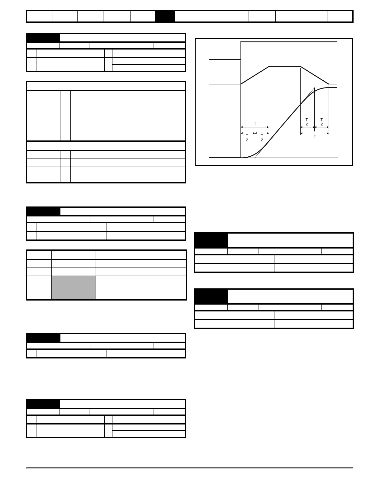
Safety
e
Information
Product
Information
Mechanical
Installation
Electrical
Installation
Getting
Star ted
Menu 0
Running
the motor
0.16 {6.01} Stop mode selector
RW Txt
OL
CL
Ú
Ú
0 to 4 (see below)
0 to 3 (see below)
Ö
VT rP (1)
Ö
SV no.rP (1)
rP (1)
Select the required stop mode as follows:
Open loop
COASt
rP (1) Ramp to a stop
rP-dcI (2) Ramp followed by 1 second DC injection
dcI (3)
td-dcI (4)
COASt
rP (1) Ramp to a stop
no.rP (2) Stop under current limiting (no ramp)
rP-POS (3) Ramp, orientate and stop
(0) The motor is allowed to coast
AC injection braking followed by 1 second DC injection
braking
DC injection braking for an adjustable time (see the
Unidrive Advanced User Guide).
Closed loop
(0) The motor is allowed to coast
For more information, see Pr 6.01 in section 10.22 Advanced
Features on page 182.
0.17 {4.11} Tor q u e mode select
RW Uni
OL
CL
Ú
Ú
0 to 1
0 to 4
Ö
Ö
0
0
Set Pr 0.17 as follows:
Setting Open-loop Closed-loop
0 Frequency control Speed control
1 Torque control Torque control
2
3
4
Torque control with speed over-ride
Coiler/uncoiler mode
Speed control with torque feed-forward
For more information, see Pr 4.11 in section 10.22 Advanced
Features on page 182.
6.2.7 S-ramp
0.18 {2.06} S-Ramp enable
RW Bit
Ú
0 or 1
Ö
Setting this parameter enables the S ramp function. S ramp is disabled
during deceleration using Standard ramp with P control (Pr 2.04 = 2).
When the motor is accelerated again after decelerating in standard ramp
with P control the acceleration ramp used by the S ramp function is reset
to zero.
0.19 {2.07} S-ramp da/dt limit
RW Uni
OL
CL
Ú
0.0 to 3,000.0s2/100Hz
Ú
0.000 to 30,000
s
2
/1,000rpm
Ö
VT 1.5
Ö
SV 0.03
This parameter defines the maximum rate of change of acceleration/
deceleration that the drive will operate with. The default values have
been chosen such that for the default ramps and maximum speed, the
0
3.1
Optimisation Macros
Advanced
Parameters
Technical
Data
Diagnostics
UL Listing
Information
curved parts of the S will be 25% of the original ramp if S ramp is
enabled.
Demanded
speed
Programmed
ramp rate
Rate of change
of S-ramp
acceleration
tim
Since the ramp rate is defined in s/100Hz or s/1000rpm and the S ramp
parameter is defined in s2 /100Hz or s2 /1,000rpm, the time T for the
'curved' part of the S can be determined from:
S ramp rate of change
------------------------------------------------------------- --
T
=
Ramp rate
Enabling S ramp increases the total ramp time by the period T since an
additional T/2 is added to each end of the ramp in producing the S.
6.2.8 Skip bands
0.20 {1.29}
0.22 {1.31}
RW Uni
OL
Ú
CL
Ú
See Pr 0.21 and Pr 0.23 Skip bands.
0.21 {1.30}
0.23 {1.32}
RW Uni
OL
Ú
CL
Ú
Use skip frequencies/speeds and skip bands to prevent the motor from
running at speeds that cause mechanical resonances in the machine.
During acceleration and deceleration, the drive passes through the skip
bands, but it does not stabilize in a skip band.
Up to two skip frequencies/speeds can be programmed.
Enter the centre frequency/speed of the band in Pr 0.20 (or Pr 0.22) Skip
frequency/speed, then enter the width of each sideband in Pr 0.21 (or Pr
0.23) Skip band.
When the value of a skip frequency is zero, the related skip band is
disabled.
Skip frequency/speed 1
Skip frequency/speed 2
0.0 to 1,000.0Hz
0 to 30,000rpm
Skip band 1
Skip band 2
0 to 5.0Hz
0 to 50rpm
Ö
Ö
Ö
Ö
0.0
0
0.5
5
Unidrive User Guide 75
Issue Number: 9 www.controltechniques.com
Page 76

Safety
Information
Product
Information
Mechanical
Installation
Electrical
Installation
Getting
Star ted
Menu 0
Figure 6-5 Action of skip frequency/speed 1 and skip band 1
Running
the motor
Optimisation Macros
Advanced
Parameters
Technical
Data
Diagnostics
6.2.10 Miscellaneous
0.27 {8.27} EUR> Positive logic select
RW Bit R P
Ú
European configuration
Use Pr 0.27 (Pr 8.27) to select the logic polarity of the digital inputs, as
follows:
0 Negative logic
1 Positive logic
0.27 {6.04} USA> Sequencing mode selector
RW Uni P
Ú
Refer to Pr 6.04 in the Unidrive Advanced User Guide.
0 or 1
0 to 4
Ö
Ö
0
4
UL Listing
Information
When the frequency/speed (input) reference ascends into a skip band,
the resulting (output) reference remains at the lower edge of the band
until the input reference has reached the upper edge of the band. The
output reference then jumps to the value of the input reference.
When the frequency/speed (input) reference descends into a skip band,
the resulting (output) reference jumps immediately to the lower edge of
the band.
Example
Skip speed 1 = 250rpm
Enter 250 in Pr 0.20
Required skip band = 60rpm
Enter 30 in Pr 0.21
(Skip band = 2 x Value of skip-band parameter.)
6.2.9 Analog input modes
0.24 {7.06}
0.25 {7.11}
RW Txt R
Ú
Set the required mode as follows:
Setting Input signal When current signal ≤3mA...
VOLt (0) ±10V
0-20 (1) 0 to 20mA Signal treated as zero
20-0 (2) 20mA to 0 Signal treated as zero
4-20.tr (3) 4mA to 20mA Drive trips
20-4.tr (4) 20mA to 4mA Drive trips
4-20.Lo (5) 4mA to 20mA Drive runs at minimum or low speed
20-4.Lo (6) 20mA to 4mA Drive runs at minimum or low speed
4-20.Pr (7) 4mA to 20mA Drive runs at previous speed
20-4.Pr (8) 20mA to 4mA Drive runs at previous speed
Analog input 1 mode selector
Analog input 2 mode selector
0 to 8
Ö
VOLt (0)
0.28 {4.13} EUR> Current-loop proportional gain
RW Uni
OL
CL
Ú
Ú
0 to 30000
VT> 0 to 30,000
SV> 0 to 30,000
Ö
Ö
20
150
130
0.29 {4.14} EUR> Current-loop integral gain
RW Uni
OL
CL
Ú
Ú
0 to 30,000
VT> 0 to 30,000
SV> 0 to 30,000
Ö
Ö
40
2000
1200
European configuration
The values of Pr 0.28 and Pr 0.29 affect the dynamic performance of the
drive in the following conditions:
• Current-limit in frequency/speed control
• Torque control
• Braking when Pr 0.15 Ramp mode selector is set at Stnd.Ct
(default)
• Synchronizing the drive to a spinning motor (Pr 0.39 set at 1)
• Loss of AC supply when Pr 6.03 AC supply loss mode selector is set
at ridE.th.
For information on adjusting these parameters, refer to Pr 4.13 and Pr
4.14 in the Unidrive Advanced User Guide.
0.28 {1.01} USA> Frequency/speed demand
RO Bi
OL
CL
Ú
Ú
±1,000Hz
±30,000rpm
Ö
Ö
USA configuration
Pr 0.28 differs from Pr 0.11 Pre-ramp reference in that it indicates the
demanded reference before frequency/speed limiting and skip bands.
0.26 {7.14} Analog input 2 destination parameter
RW Txt R P
Pr 0.00 to Pr 21.50 (Menu param.)
Ú
Ö
Pr 1.37
A signal applied to an input terminal is converted into a value which is
applied to a parameter. The function of this parameter determines the
function of the terminal.
0.29 {8.23} USA> Terminal-29 destination parameter
RW Uni R P
Pr 0.00 to Pr 20.50 (Menu param.)
Ú
Ö
Pr 1.41
USA configuration
Use Pr 0.29 to change the function of the digital input on terminal 29.
The default setting (Pr 1.41) gives LOCAL/REMOTE switching.
By default, terminal 7 (Analog input 2) is assigned to Pr 1.37 Analog
reference 2. Use Pr 0.26 to change the function of terminal 7.
76 Unidrive User Guide
www.controltechniques.com Issue Number: 9
Page 77

Safety
Information
Product
Information
Mechanical
Installation
Electrical
Installation
Getting
Star ted
Menu 0
0.30 {6.13} Forward / reverse key enable
RW Bit
Ú
0 or 1
Ö
0
The drive is supplied with the button disabled. To enable this
button, set Pr 0.30 FWD/REV enable at 1.
0.31 {11.37} Macro number
RO Uni
Ú
0 to 9
Ö
Pr 0.31 indicates the number of the macro that is currently in operation.
Running
the motor
Optimisation Macros
Advanced
Parameters
Technical
Data
Diagnostics
6.2.12 Serial communications,
Parameter displayed after power-up
0.36 {11.25} Serial comms. baud rate
RW Txt P
4,800 (0)
Ú
9,600 (1)
19,200 (2)
2,400 (3)
Ö
*This parameter has a default setting of 9,600 (1) in the VTC variant
when USA defaults are loaded.
Use Pr 0.36 to select the required baud rate for serial communications
when a UD71 Basic serial communications large option module is fitted
in the drive.
4800 (0)*
UL Listing
Information
0.32 {11.24} Serial comms. mode
RW Uni R P
ANSI 2 (0)
Ú
ANSI 4 (1)
OUtPUt (2)
INPUt (3)
Ö
ANSI 4 (1)
Use Pr 0.32 to select the required serial communications mode as
follows:
ANSI 2 (0) ANSI protocol, two-wire
ANSI 4 (1) ANSI protocol, four-wire
Use the following modes to transfer the value of a parameter in one
drive to a parameter in another drive:
OUtPUt (2)
INPUt (3)
Transmit the value of the parameter specified by the setting of
11.27 Serial comms. source / destination parameter
Pr
(CT protocol)
Apply the received value to the parameter specified by the setting
11.27 Serial comms. source / destination parameter (CT
of Pr
protocol)
0.33 {11.32} Drive rated current (FLC)
RO Uni P
Ú
2.10 to 1,920 A
Ö
0.34 {11.30} User security code
RW Uni S P
Ú
0 to 255
Ö
149
Use Pr 0.34 to set up a User Security code. Irrespective of the code
number entered in Pr 0.34, it always indicates the default value 149.
When Pr 0.34 is actually set at 149, no User Security is applied.
See section 5.10 Parameter security on page 62.
6.2.11 Keypad-reference monitoring
0.35 {1.17} Keypad control mode reference
RO Bi S P
OL
Ú
CL
Ú
0.35 indicates the value of the frequency/speed reference when the
drive is operating in Keypad mode. The reference is then controlled by
the following control buttons (when the display is in Status mode):
The value is automatically saved when the drive is powered-down. At
the next power-up, the drive ramps up to the frequency/speed that
applied before the power-down.
±[Pr 0.02]Hz
±[Pr 0.02]rpm
Ö
Ö
0.37 {11.23} Serial comms. address
RW Uni P
Ú
0.0 to 9.9 (Group.Unit)
Ö
1.1
Use Pr 0.37 to select the required address for serial communications
when a UD71 Serial communications large option module is fitted in the
drive.
Do not enter an address that contains a zero, since this is used when
addressing a group of drives.
0.38 {11.22} Initial parameter displayed
RW Uni P
Ú
Pr 0.00 to Pr 0.50
Ö
Pr 0.10*
*This parameter has a default setting of Pr 0.11 in the VTC variant when
USA defaults are loaded.
At the time the AC supply is connected to the drive, Pr 0.10 Motor
frequency/speed is automatically pre-selected as the initial parameter to
be displayed. This results in the following:
1. After the AC supply is connected to the drive, and before any other
parameter is selected, the value of Pr 0.10 is shown on the upper
display. This allows the motor frequency/speed to be monitored
without the need to select the parameter.
2. If the keypad is subsequently used to select another parameter, the
value of the newly selected parameter is displayed in place of the
initial parameter.
To select a different Menu 0 parameter to be displayed initially, enter the
required parameter number in Pr 0.38 (e.g. to display Pr 0.12 Post-ramp
frequency/speed reference, enter 0.12).
6.2.13 Spinning motor, Autotune, PWM switching frequency
0.39 {6.09} Synchronise to a spinning motor
RW Bit
OL
Ú
CL
Ú
Open-loop
Set Pr 0.39 at 1 for the drive to always automatically synchronise itself to
the motor if the motor is already rotating when the drive is started.
If the drive is started when the motor is already spinning and Pr 0.39 is
set at 0, the drive cannot detect the speed of the motor; the normal
operation of the drive will cause the motor to be braked to a stand-still in
the same way as
motor to the value of the frequency reference.
NOTE
Note
The drive can be synchronised to a single motor only. If more than one
motor is connected to the drive, this function should not be used.
0 or 1
0 or 1
DC injection braking. The drive will then accelerate the
Ö
Ö
0
1
Unidrive User Guide 77
Issue Number: 9 www.controltechniques.com
Page 78

Safety
Information
Product
Information
Mechanical
Installation
Electrical
Installation
Getting
Star ted
Menu 0
Running
the motor
Optimisation Macros
Advanced
Parameters
Technical
Data
Diagnostics
UL Listing
Information
NOTE
Note
For the drive to operate correctly during and after synchronisation, Pr
0.07 Voltage mode selector must be set at Fd.
The drive starts a sequence of operations at one quarter of the rated
motor voltage in order to detect the frequency associated with the speed
of the motor. The sequence is stopped when the motor frequency is
detected. The stages in the sequence are as follows:
1. The frequency of the drive is set at maximum (the value of Pr 0.02)
in the direction that the motor was last driven. (If the AC supply to
the drive was interrupted before an attempt is made to synchronise
to a spinning motor, the drive always starts in the forward direction.)
2. The frequency is reduced to zero. If the motor frequency is detected
during the reduction in drive frequency, the test is stopped. The drive
frequency is set at the detected motor frequency and the drive takes
control of the motor.
3. If the motor frequency is not detected, the drive is set at maximum
frequency in the opposite direction, and the test is repeated.
4. If the motor frequency is still not detected, the drive frequency is set
at 0Hz, and the drive takes control of the motor.
Closed-loop
Pr 0.39 is set at 1 by default. The value of Pr 0.12 Post-ramp reference
is automatically set at the value of speed feedback. The drive then takes
control of the motor.
When Pr 0.39 is set at 0, the motor will be decelerated under current limit
until the motor speed meets the value of Pr 0.12 Post-ramp reference.
For more information, see section 10.22 Advanced Features on
page 182.
NOTE
Note
The Unidrive LFT default switching frequency is 9kHz, however, a limited
duty cycle applies. See Figure 2-3 Standard S4/S5 duty cycle (Unidrive
LFT) on page 10.
6.2.14 Motor parameters
0.42 {5.11} Motor - number of poles
RW Txt P
OL
Ú
CL
Ú
Enter the number of motor poles (not pole pairs).
0.43 {5.10} Motor - power factor
RW Uni S P
OL
Ú
CL
Ú
Open-loop
Closed-loop Vector
When Autotune is used, the power factor of the motor is measured by
the drive and stored in Pr 0.43. The value can be seen when Pr 0.43 is
accessed. The value may be slightly higher than the value stated on the
motor rating plate.
If Autotune is not used, enter the value in Pr 0.43.
2 to 32 poles
VT> 2 to 32 poles
SV> 2 to 32 poles
0 to 1.000
VT> 0 to 1.000
SV> 1
Ö
Ö
Ö
Ö
4 (1)
4 (1)
6 (2)
0.92
0.92
1.0
0.40 {5.12} Autotune
RW Bit P
Ú
0 or 1
Ö
0
Set Pr 0.40 at 1 to start the Autotune sequence. See Chapter
8 Optimisation .
Pr 0.40 is related to the advanced parameters as follows:
OL + VT> Pr 5.12 Magnetizing current test enable
SV> Pr 3.25 Encoder phasing test enable
0.41 {5.18} PWM switching frequency
RW Txt
3 (0), 4.5 (1), 6 (2), 9 (3),
Ú
12 (4) kHz
Ö
3 (0)
If the switching frequency is increased from the default value, the power
loss inside the drive is increased. The drive ensures the losses remain
within acceptable levels by the use of an intelligent thermal model.
Intelligent thermal modelling in the drive effectively monitors the junction
temperature of the IGBTs in the power stage. When the junction
temperature is calculated to reach the maximum permissible value, two
levels of protection occur, as follows:
1. When a PWM switching frequency of 6kHz, 9kHz or 12kHz is
selected, the PWM switching frequency is automatically halved. This
reduces switching losses in the IGBTs. (The value of parameter Pr
0.41 PWM switching frequency remains at the value set by the user.)
Then at one-second intervals, the drive will attempt to return the
PWM switching frequency to the original value. This will be
successful when the thermal modelling has calculated that the
temperature has reduced sufficiently.
2. If the junction temperature continues to rise (due to the output
current) after the PWM switching frequency has been halved, and
the temperature reaches the maximum permissible value, the drive
will trip. The display will indicate trip code Oh1.
If the drive is required to run at a high load continuously with an elevated
switching frequency, derating must be applied. Please see Table 111 Unidrive and Unidrive VTC drive current ratings on page 190.
0.44 {5.09} Motor - rated voltage
RW Uni
OL
CL
Ú
Ú
0 to 480
VT> 0 to 480
SV> 0
Ö
Ö
400
460
0
Open-loop and Closed-loop Vector
Enter the value from the rating plate of the motor.
0.45 {5.08} Motor - rated speed
RW Uni
OL
CL
Ú
Ú
0 to 6,000rpm
VT> 0 to 30,000rpm
SV> 0 to 30,000rpm
Ö
Ö
0
EUR> 1,450
USA> 1,770
0
Open-loop
This parameter should be set to the synchronous speed minus the slip
speed if slip compensation is required.
Closed-loop Vector
This parameter should be set to the synchronous speed minus the slip
speed.
Closed-loop Servo
Leave Pr 0.45 set at 0. This parameter is not used in this operating
mode.
0.46 {5.07} Motor - rated current
RW Uni
Ú
0 to FLC A
Ö
FLC
FLC is the maximum permissible continuous output current of the drive
up to 40°C ambient temperature and 3kHz PWM switching frequency.
Enter the value from the rating plate of the motor.
78 Unidrive User Guide
www.controltechniques.com Issue Number: 9
Page 79

Safety
Information
Product
Information
Mechanical
Installation
Electrical
Installation
Getting
Star ted
Menu 0
Running
the motor
Optimisation Macros
Advanced
Parameters
Technical
Data
Diagnostics
UL Listing
Information
0.47 {5.06} Motor - rated frequency
RW Bit
OL
CL
Ú
Ú
0 to 1,000.0Hz*
VT> 0 to 1,000.0Hz
SV> 0Hz
Ö
Ö
EUR> 50
USA> 60
EUR> 50
USA> 60
0
*This parameter has a maximum range of 250Hz in Unidrive VTC.
Open-loop and Closed-loop Vector
Enter the value from the rating plate of the motor.
6.2.15 Operating-mode selection
0.48 {11.31} Drive operating mode selector
RW Txt R P
Ú
(See below)
Ö
The settings for 0.48 are as follows:
Pr 0.48 setting Operating mode
0 Open-loop
1
Closed-loop Vector
OPEN.LP (0)
NOTE
In contrast to all the other parameters in menu 0, this parameter does
not exist in any other menu.
0.50 {11.29} Software version number
RO Uni P
Ú
1.00 to 99.99
Ö
Displays the first two sections of the software version of the drive.
6.2.17 Unidrive VTC Menu 0 differences
Menu 0 in Unidrive VTC contains some different parameters to menu 0
in Unidrive. The following menu 0 parameters are found in Unidrive VTC.
Any parameter not listed below is the same as open loop Unidrive.
0.14 {4.01} Total motor current
RO Uni P
Ú
0 to I
Pr 0.14 indicates the total motor current (the vector sum of Pr 0.13 Motor
active-current and Pr 4.17 Motor magnetising current).
0.17 {5.03} To tal mo t o r powe r
RO Bi P
Ú
Total output power of the drive (positive for power flow out of the drive
output terminals).
±P
MAX
MAX
A
Ö
Ö
2
For operation in this mode, refer to the
3
Closed-loop Servo
Unidrive Regen Installation Guide
See Chapter 8 Optimisation on page 92.
The operating mode cannot be changed while the drive is running.
6.2.16 Status information
0.49 Security status
RO Uni P
Ú
0 to 1,000
Ö
This parameter indicates the current status of the drive parameter
security system. Each digit indicates a particular aspect of security as
follows:
Units digit: 0 = Standard security has been unlocked
1 = Standard security is still set
Tens digit: 0 = User security has been unlocked or is not active
1 = User security is active preventing RW access
Hundreds digit: 1 = Pr 11.30 not equal to 149*
Thousands digit: 1 = Pr 11.30 equal to zero*
* The value of Pr 11.30 is the last value written by the user. Pr 11. 30
always appears as 149 when first accessed by the key pad to hide the
real value last written by the user. If Pr 11.30 = 149 then user security is
cleared. If Pr 11.30 = 0 then user security and security preventing
access outside menu 0 is cleared.
1
0.22 Drive rated current
RO Uni P
Ú
2.10 to 202 A
Ö
0.23 Analog input 1 mode selector
RW Txt R
VOLt (0), 0 - 20 (1), 20 - 0 (2),
Ú
4 - 20.tr (3), 20 - 4.tr (4),
4 - 20.Lo (5), 20 - 4.Lo (6),
4 - 20.Pr (7), 20 - 4.Pr (8)
Setting Input signal
VOLt (0) ±10V
0-20 (1) 0 to 20mA Signal treated as zero
20-0 (2) 20mA to 0 Signal treated as zero
4-20.tr (3) 4mA to 20mA Drive trips
20-4.tr (4) 20mA to 4mA Drive trips
4-20.Lo (5) 4mA to 20mA Drive runs at minimum or low speed
20-4.Lo (6) 20mA to 4mA Drive runs at minimum or low speed
4-20.Pr (7) 4mA to 20mA Drive runs at previous speed
20-4.Pr (8) 20mA to 4mA Drive runs at previous speed
Ö
When current signal
VOLt (0)
≤30mA
0.24 {1.21} Preset frequency 1
0.25 {1.22} Preset frequency 2
RW Bi
Ú
±1000.0 Hz
Ö
0.0
Enter the value of frequency as required. When Pr 1.10 Bipolar
reference select is set at 0, negative values are treated as zero. When
Pr 1.10 is set at 1, negative values will cause the drive to run in the
reverse direction.
Unidrive User Guide 79
Issue Number: 9 www.controltechniques.com
Page 80

Safety
Information
Product
Information
Mechanical
Installation
Electrical
Installation
Getting
Star ted
Menu 0
Running
the motor
0.26 {2.08} Standard ramp voltage
RW Uni
Ú
200V drive: 0 to 400 V
400V drive: 0 to 800 V
Ö
200V drive: 375
400V drive: EUR> 750, USA> 775
This voltage is used as the level for both standard ramp modes. If hold
mode is used and this is set too low the drive will never stop, and if it is
too high and no braking resistor is used the drive may trip on OV (DC
bus over voltage). If Standard ramp with P control (Pr 2.04 = Stnd.Ct (2))
is used and Pr 2.08 is set too low the machine will coast to rest, and if it
is set too high and no braking resistor is used it may trip on OV. The
minimum level should be greater than the voltage produced on the DC
bus by the highest supply voltage.
Normally the DC bus voltage will be approximately the rms supply
voltage x √2.
Care should be taken in the setting of Pr 2.08. It is
recommended that the setting should be at least 50V higher
than the maximum expected level of the DC bus voltage. If
WARNING
this is not done, the motor may fail to decelerate on a STOP
command.
0.27 {4.13} Current-loop proportional gain
RW Uni
Ú
0 to 30,000
Ö
20
0.28 {4.14} Current-loop integral gain
RW Uni
Ú
0 to 30,000
Ö
40
The values of Pr 0.27 and Pr 0.28 affect the dynamic performance of the
drive in the following conditions:
• Operation in current limit
• Braking when Pr 0.15 Ramp mode selector is set at Stnd.Ct (default)
• Loss of AC supply when Pr 6.03 AC supply loss mode selector is set
at ridE.th.
See section 10.22.5 Mains loss modes on page 185 for more
information.
0.29 {5.05} DC bus voltage
RW Uni P
Ú
200V drive: 0 to 415 V
400V drive: 0 to 830 V
Ö
0.30 {10.20} Last trip
RW Txt S P
Ú
0 to 200 V
Ö
See section 12.1 Trip indications on page 198 for details of the trip
codes.
If the drive trips, the trip code representing the cause of the trip is logged
in Pr 0.30. Pr 0.30 continues to display this trip until the drive trips with a
different trip code.
Optimisation Macros
Advanced
Parameters
Technical
Data
Diagnostics
UL Listing
Information
reset count reaches the programmed value, any further trip of the same
value will not cause an auto-reset.
If there has been no trip for 5 minutes then the reset count is cleared.
Auto reset will not occur on an External trip (Et).
0.33 {10.35} Auto-reset time delay
RW Uni
Ú
0.0 to 25.0 s
Ö
1.0
This parameter defines the time between a trip and an auto reset subject
to the 10s minimum trip time for IGBT over-current trips (OI.AC and OI.br
trips).
0.35 {11.24} Serial comms. mode
RW Txt R P
Ú
ANSI 2 (0), ANSI 4 (1),
OUtPUt (2), INPUt (3)
Ö
ANSI 4 (1)
Use Pr 0.32 to select the required serial communications mode as
follows:
ANSI 2 (0) ANSI protocol, two-wire
ANSI 4 (1) ANSI protocol, four-wire
Use the following modes to transfer the value of a parameter in one
drive to a parameter in another drive:
OUtPUt (2)
INPUt (3)
Transmit the value of the parameter specified by the setting of
11. 27 Serial comms. source / destination parameter
Pr
(CT protocol)
Apply the received value to the parameter specified by the setting
11.27 Serial comms. source / destination parameter (CT
of Pr
protocol)
0.48 {4.19} Overload accumulator
RO Uni P
Ú
0 to 100 %
Ö
When the total current level is above 105% motor rated current (Pr 5.07
x 1.05) the overload accumulator increases, until it reaches 100% when
the drive will give an Ixt trip or apply a restriction on the current limit. The
level of the accumulator is given by:
Accumulator = (I
NOTE
If the motor rated current parameter (Pr 5.07) is modified the overload
2
/ (Pr 5.07 x 1.05)2) x (1 - e
-t/τ
) x 100%
accumulator is reset to zero. This allows the drive to be used with more
than one motor of different ratings without producing overload trips when
the drive has been running with a large motor and then a smaller motor
is connected.
0.32 {10.34} Number of auto-reset attempts
RW Uni
Ú
0 to 5
Ö
0
If this parameter is set to zero then no auto-reset attempts are made.
Any other value will cause the drive to automatically reset following a trip
for the number of times programmed. Pr 10.35 defines the time between
the trip and the auto reset. The reset count is only incremented when the
trip is the same as the previous trip, otherwise it is reset to 0. When the
80 Unidrive User Guide
www.controltechniques.com Issue Number: 9
Page 81

Safety
Information
Product
Information
Mechanical
Installation
Electrical
Installation
7 Running the motor
Ensure that no damage or safety hazard could arise from the
motor starting unexpectedly.
WARNING
Motor overload protection
The values of the motor parameters affect the protection of
the motor. The default values in the drive should not be relied
CAUTION
CAUTION
WARNING
upon. It is essential that the correct value is entered in Pr 0.46
Motor rated current. The overload protection level is 150%
(SV: 175%) of motor rated current. The protection level
maybe adjusted below 150% if required. Refer to Chapter
8 Optimisation on page 92 for further information. These
settings affect the thermal protection of the motor.
If the keypad mode has been used previously, ensure that the
keypad reference has been set to 0 using the and
buttons as if the drive is started using the keypad it will run to
the speed defined by the keypad reference (Pr 0.35).
If the intended maximum speed affects the safety of the
machinery, additional independent over-speed protection
must be used.
Getting
Star ted
Menu 0
Running
the motor
Optimisation Macros
Advanced
Parameters
Technical
Data
Diagnostics
For operation with a resolver or SINCOS encoder an option module is
required. For option module terminal information see section
10.16 Menu 16 Small option module set-up on page 171 or the manual
which is supplied with the option module.
7.1.2 Selecting the operating mode
Changing the operating mode returns all parameters to their default
value, including the motor parameters.
Procedure
1. Enter either of the following values in parameter 0.00, as
appropriate:
1253 (Europe, 50Hz AC supply frequency)
1254 (USA, 60Hz AC supply frequency)
2. Change the setting of parameter 0.48 as follows:
Pr 0.48 setting Operating mode
0 Open-loop
1
2
Closed-loop Vector
Closed-loop Servo
UL Listing
Information
7.1 Quick start set-up
7.1.1 Basic connections
This section shows the basic connections which must be made for the
drive to run in the required mode. For minimal parameter settings to run
in each mode please see the relevant part of section 7.2 Quick Start
commissioning .
Tab le 7-1
Drive control method Requirements
Drive enable
Terminal mode (Default
configuration)
Keypad mode (Set Pr 0.05 = 4) Drive enable
Tab le 7-2
Operating mode Requirements
Open loop mode Induction motor
Closed loop vector mode
Servo
Speed feedback
Suitable devices are:
• Incremental encoder (A, B),
• Resolver with 0.33 or 0.5 transformation ratio
• SINCOS encoder
Speed reference
Run forward or run reverse
command
Connect thermistor or link to 0V
Connect thermistor or link to 0V
Induction motor with speed
feedback
Permanent magnet motor with
speed and position feedback
For operation in this mode, refer to the
3
Unidrive Regen Installation Guide
The figures apply when serial communications are used.
3. Press or momentarily close the RESET contact.
The new setting takes effect and all the parameters revert to the
appropriate default values for the new mode.
Speed and position feedback
Suitable devices are:
• Incremental encoder with commutation signals (A, B, U, V, W)
• Resolver with 0.33 or 0.5 transformation ratio
• Stegmann SINCOS encoder with Hiperface serial communications
Unidrive User Guide 81
Issue Number: 9 www.controltechniques.com
Page 82

Safety
Information
Figure 7-1 Minimum connections to get the motor running in any operating mode
Product
Information
C
l
o
s
e
d
L
o
o
p
V
e
c
t
Mechanical
Installation
O
p
e
n
L
o
o
p
Electrical
Installation
UVW
A A
B B
Z Z
Getting
Star ted
Menu 0
E
1
Running
the motor
Quadrature channel A
Quadrature channel A
Quadrature channel B
Quadrature channel B
Marker pulse channel Z
Marker pulse channel Z
Commutation channel U
Commutation channel U
Commutation channel V
Commutation channel V
Commutation channel W
Commutation channel W
Encoder supply
0V Common
Motor thermistor input
5
10
15
3
Encoder connector
Optimisation Macros
15 way D-type
o
r
Advanced
Parameters
5
1
6
11
L1 L2 L3 U V W +
Technical
Data
_
Diagnostics
!
UL Listing
Information
S
e
v
o
4
UVW
Braking
resistor
r
A A
B B
U U
V V
Marker pulse optional
1
Link to 0V if motor thermistor not present
2
Encoder screening must be connected to 0V at both
3
the drive end and encoder end of the cable
4
Thermal overload for braking resistor to protect against
fire risk. This must be wired to interrupt the AC supply in
the event of a fault.
Encoder power supply:
5
5V, parameter = 0
15V, parameter = 1
3.23
3.23
W W
Z Z
E
1
Fuses
L1 L2 L3
82 Unidrive User Guide
www.controltechniques.com Issue Number: 9
Page 83

Safety
y
Information
Product
Information
Mechanical
Installation
1
2
3
4
5
6
7
8
9
10
11
Electrical
Installation
Getting
Star ted
+10V
Speed
reference
input
2
Thermistor input
0V
Menu 0
Running
the motor
Optimisation Macros
21
22
23
24
25
26
27
28
29
30
31
Advanced
Parameters
RUN FWD
RUN REV
ENABLE
0V
Technical
Data
K
e
p
a
d
Diagnostics
T
e
r
m
i
n
a
l
m
o
d
e
UL Listing
Information
m
o
d
e
(
0.05
= 4)
Unidrive User Guide 83
Issue Number: 9 www.controltechniques.com
Page 84

Safety
Information
Product
Information
Mechanical
Installation
Electrical
Installation
Getting
Star ted
Menu 0
Running
the motor
7.2 Quick Start commissioning
7.2.1 Open loop mode (including VTC variant)
Induction motor without feedback device
Action Detail
Ensure:
• Enable is closed (terminal 30)
• Motor thermistor is connected or terminal 8 is linked to 0V
Before powerup
• Run signal is not given
• Motor is connected
NOTE
The motor must be uncoupled from any gearbox or load before an autotune is carried out, as
detailed below.
Optimisation Macros
Advanced
Parameters
Technical
Data
Diagnostics
UL Listing
Information
Power-up the
drive
Enter motor
nameplate
details
Set maximum
frequency
Set acceleration
/ deceleration
rates
Autotune
Save
parameters
Ensure:
• Drive displays ‘rdy’
If the drive trips, see Chapter 12 Diagnostics on page 198.
Enter:
• Motor rated current in Pr 0.46 (A)
• Motor rated frequency in Pr 0.47 (Hz)
• Motor rated voltage in Pr 0.44 (V) - check if or connection
• Number of poles in Pr 0.42
f120×
------------------
P
=
Where:
N
s
P = Number of poles
f = Rated frequency (Hz)
N
= Synchronous speed (rpm)
s
Enter:
• Maximum frequency in Pr 0.02 (Hz)
Enter:
• Acceleration rate in Pr 0.03 (s/100Hz)
• Deceleration rate in Pr 0.04 (s/100Hz)
Once this parameter is set, the motor will accelerate up to 2/3 base frequency
without a run command being given. Once the measurement is complete, the
motor will coast to a stop. The drive can be disabled at any time by pressing the
WARNING
red button.
•Set Pr 0.40 = 1 and wait for the drive display to return to ‘rdy’
If the drive trips, see Chapter 12 Diagnostics on page 198.
NOTE
The motor must be uncoupled from any gearbox or load before an autotune is carried out.
Enter 1000 in Pr xx.00
Press the red reset button or toggle the reset digital input (ensure Pr xx.00 returns to 0)
Mot X XXXXXXXXX
No XXXXXXXXXX kg
IP55 I.cl F C 40 s S1
CTP- VEN 1PHASE 1=0, 46A P=110W R.F 32MN
0.02
100Hz
°
VHzmin-1kW cosφA
230
50 1445 2.20 0.80 8.50
400
CN = 14.5Nm
240
50 1445 2.20 0.76 8 .50
415
CN = 14.4Nm
0.03
cos = ?
∅
4.90
4.90
0.04
I.E.C 34 1(87)
t
t
Run Drive is now ready to run
84 Unidrive User Guide
www.controltechniques.com Issue Number: 9
Page 85

Safety
Information
Product
Information
Mechanical
Installation
Electrical
Installation
Getting
Star ted
Menu 0
Running
the motor
7.2.2 Closed loop vector mode
Induction motor with speed feedback
Action Detail
Ensure:
• Enable signal is not given (terminal 30)
• Motor thermistor is connected or terminal 8 is linked to 0V
Before power-up
Power-up the
drive
Set feedback
device
parameters
Enter motor
nameplate details
• Run signal is not given
• Motor is connected
• Feedback device is connected
NOTE
The motor must be uncoupled from any gearbox or load before an autotune is carried out.
• Change drive operating mode to closed loop vector
Set Pr xx.00 to 1253 / 1254 (USA).
Change Pr 0.48 to ‘CL.UECt’
Press the reset button
• Ensure the drive displays ‘inh’ (‘SEP.EC’ trip if 8V SINCOS encoder feedback is being used)
If the drive trips, see Chapter 12 Diagnostics on page 198.
Encoder
• Encoder power supply
Pr 3.23 = 0, 5V
Pr 3.23 = 1, 15V. (If Pr 3.23 = 1 then termination resistors should be disabled - Pr 3.24 = 1)
• Encoder PPR (pulses per revolution)
Enter PPR in Pr 3.21
Resolver
• The default setting is for a transformation ratio of 0.33 (3:1), if the resolver has a transformation
ratio of 0.5 (2:1), set Pr 16.10 = 1
SINCOS
• Encoder power supply
Pr 16.15 = 0, 5V
Pr 16.15 = 1, 8V. (Save parameters and cycle power to clear ‘SEP.EC’ trip)
• Encoder PPR (pulses per revolution)
Enter PPR in Pr 16.12
Enter:
• Motor rated power factor Pr 0.43
• Motor rated voltage in Pr 0.44 (V) - check if or connection
• Motor rated speed (synchronous speed - slip speed) in Pr 0.45 (rpm)
• Motor rated current in Pr 0.46 (A)
• Motor rated frequency in Pr 0.47 (Hz)
• Number of poles in Pr 0.42
f 120×
------------------
P
=
N
s
Where: P = Number of poles, f = Rated frequency (Hz), N
Optimisation Macros
= Synchronous speed (rpm)
s
Advanced
Parameters
Technical
Data
Diagnostics
IP55 I.cl F C 40 s S1
VHzmin-1kW cosφA
230
400
240
415
CTP- VEN 1PHASE 1=0,46A P=110W R.F 32MN
UL Listing
Information
Mot X XXXXXXXXX
No XXXXXXXXXX kg
°
50 1445 2.20 0.80 8.50
CN = 14.5Nm
50 1445 2.20 0.76 8.50
CN = 14.4Nm
4.90
4.90
I.E.C 34 1(87)
Set maximum
speed
Set acceleration /
deceleration rates
Enter:
• Maximum speed in Pr 0.02 (rpm)
Enter:
• Acceleration rate in Pr 0.03 (s/1,000rpm)
• Deceleration rate in Pr 0.04 (s/1,000rpm) (If braking resistor fitted, set Pr 0.15 = FAST)
0.02
1000rpm
t
0.03
t
0.04
• Close enable signal
Autotune
Once this parameter is set and the enable signal is given, the motor will accelerate up to
2
/3 base frequency without a run command being given. Once the measurement is
complete, the motor will coast to a stop. The drive can be disabled at any time by
WARNING
pressing the red button.
•Set Pr 0.40 = 1 and wait for the drive display to return to ‘rdy’
If the drive trips, see Chapter 12 Diagnostics on page 198.
NOTE
L = ?
S
cos = ?
∅
T
Nm
= ?
N rpm
The motor must be uncoupled from any gearbox or load before an autotune is carried out.
Save parameters
Enter 1000 in Pr xx.00
Press the red reset button or toggle the reset digital input (ensure Pr xx.00 returns to 0)
Run Drive is now ready to run
Unidrive User Guide 85
Issue Number: 9 www.controltechniques.com
Page 86

Safety
t
t
Information
Product
Information
Mechanical
Installation
Electrical
Installation
Getting
Star ted
Menu 0
Running
the motor
7.2.3 Servo
Permanent magnet motor with speed and position feedback
Action Detail
Ensure:
• Enable signal is not given (terminal 30)
• Motor thermistor is connected or terminal 8 is linked to 0V
Before powerup
Power-up the
drive
Set feedback
device
parameters
• Run signal is not given
• Motor is connected
• Feedback device is connected (U, V, W required for incremental encoders)
NOTE
The motor must be uncoupled from any gearbox or load before an autotune is carried out.
• Change drive operating mode to servo
Set Pr xx.00 to 1253 / 1254 (USA).
Change Pr 0.48 to ‘SErUO’
Press the reset button
• Ensure the drive displays ‘inh’ (‘SEP.EC’ trip if 8V SINCOS encoder feedback is being used)
If the drive trips, see Chapter 12 Diagnostics
on page 198.
Encoder
• Encoder power supply
Pr 3.23 = 0, 5V
Pr 3.23 = 1, 15V. (If Pr 3.23 = 1 then termination resistors should be disabled - Pr 3.24 =
1)
• Encoder PPR (pulses per revolution)
Enter PPR in Pr 3.21
Resolver
• The default setting is for a transformation ratio of 0.33 (3:1), if the resolver has a
transformation ratio of 0.5 (2:1), set Pr 16.10 = 1
SINCOS
• Encoder power supply
Pr 16.15 = 0, 5V
Pr 16.15 = 1, 8V. (Save parameter and cycle power to clear ‘SEP.EC’ trip)
• Encoder PPR (pulses per revolution)
Enter PPR in Pr 16.12
Optimisation Macros
Advanced
Parameters
Technical
Data
Diagnostics
UL Listing
Information
Enter motor
nameplate
details
Set maximum
speed
Set
acceleration /
deceleration
rates
Autotune
Save
parameters
Enter:
• Motor rated current in Pr 0.46 (A)
• Number of poles in Pr 0.42
Enter:
• Maximum speed in Pr 0.02 (rpm)
Enter:
• Acceleration rate in Pr 0.03 (s/1,000rpm)
• Deceleration rate in Pr 0.04 (s/1,000rpm) (If braking resistor fitted, set Pr 0.15 = FAST)
Once this parameter is set and the enable signal is given, the motor will rotate by part
of 1 revolution without a run command being given.
WARNING
•Set Pr 0.40 = 1, close the enable signal (terminal 30) and wait for the drive display to show
‘StOP’
If the drive trips, see Chapter 12 Diagnostics on page 198.
NOTE
The motor must be uncoupled from any gearbox or load before an autotune is carried out.
Enter 1000 in Pr xx.00
Press the red reset button or toggle the reset digital input (ensure Pr xx.00 returns to 0)
Model No: 95UXXXXXXXXXXXX
Volts: 380/480
Cont: 7.7Nm:4.81Arms
Stall: 9.5Nm:5.91Arms
Speed: 3000rpm Poles:6
Kt: 1.6Nm/Arms
Ins Class: H
Serial No: XXXXXXXXXXX
0.02
1000rpm
0.03
0
Brake: 12Nm
24V
0.67A
Control Techniques
Dynamics Ltd
ANDOVER, HANTS.
ENGLAND. SP10 5AB
0.04
0
Run Drive is now ready to run
86 Unidrive User Guide
www.controltechniques.com Issue Number: 9
Page 87

Safety
Information
Product
Information
Mechanical
Installation
Electrical
Installation
Getting
Star ted
Menu 0
Running
the motor
Optimisation Macros
Advanced
Parameters
Technical
Data
Diagnostics
UL Listing
Information
7.3 Quick start P.C. commissioning (UniSoft / VTCSoft)
This section details how to get the motor running using Unisoft or VTCsoft pc commissioning software in each operating mode and with the various
feedback devices.
Unisoft or VTCsoft is available free of charge and can be downloaded from www.controltechniques.com.
7.3.1 Open Loop
Induction motor without feedback device
Please refer to the documentation that came with UniSoft or VTCSoft for instructions on how to install the drive commissioning software.
Enter motor nameplate details.
Select OPEN
LOOP mode
of operation
When entering the motor nameplate details, max/min speeds and acceleration/deceleration
rates, click on the relevant field, enter the value here and click ‘Change’
Action Detail
Ensure:
• Enable is closed (terminal 30)
• Motor thermistor is connected or terminal 8 is linked to 0V
• Run signal is not given
Before power-up
• Motor is connected
• A UD71 serial communications module is fitted and is connected to the PC running UniSoft with the
above screen displayed
NOTE
The motor must be uncoupled from any gearbox or load before an autotune is carried out.
Mot X XXXXXXXXX
No XXXXXXXXXX kg
IP55 I.cl F C 40 s S1
CTP- VEN 1PHASE 1=0,46A P=110W R.F 32MN
°
VHzmin-1kW cosφA
230
50 1445 2.20 0.80 8.50
400
CN = 14.5Nm
240
50 1445 2.20 0.76 8.50
415
CN = 14.4Nm
4.90
4.90
I.E.C 34 1(87)
Set maximum / minimum speed.
0.02
t
Set acceleration / deceleration rates.
100Hz
0.03
0.04
t
Power-up the
drive
Ensure:
• Drive displays ‘inh’. If the drive trips, refer to Chapter 12 Diagnostics on page 198.
Program the drive Click ‘Program’ to upload the values to the drive.
Once this parameter is set, the motor will accelerate up to 2/3 base frequency
without a run command being given. Once the measurement is complete, the
Autotune
WARNING
motor will coast to a stop. The drive can be disabled at any time by pressing the
red button.
cos = ?
∅
• Click ‘Autotune’ to enable the drive to perform the autotune
If the drive trips, see Chapter 12 Diagnostics on page 198.
NOTE
The motor must be uncoupled from any gearbox or load before an autotune is carried out.
Saving
parameters
In the 'Tools' menu select 'Save parameters in drive'. UniSoft will ask whether you want to save
parameters in the drive when UniSoft is closed.
Run Drive is now ready to run
Unidrive User Guide 87
Issue Number: 9 www.controltechniques.com
Page 88

Safety
t
Information
Product
Information
Mechanical
Installation
Electrical
Installation
Getting
Star ted
Menu 0
Running
the motor
7.3.2 Closed Loop Vector
Induction motor with speed feedback
Please refer to the documentation that came with UniSoft for instructions
on how to install the drive commissioning software
Select Flux Vector
mode of operation
Optimisation Macros
Advanced
Parameters
Technical
Data
Diagnostics
UL Listing
Information
Enter motor nameplate details
Mot X XXXXXXXXX
No XXXXXXXXXX kg
IP55 I.cl F C 40 s S1
°
VHzmin-1kW cosφA
230
50 1445 2.20 0.80 8.50
400
240
50 1445 2.20 0.76 8.50
415
CTP- VEN 1PHASE 1=0,46A P=110W R.F 32MN
CN = 14.5Nm
CN = 14.4Nm
4.90
4.90
I.E.C 34 1(87)
Set max / min speed
0.02
Set acceleration / deceleration
rates
100Hz
When entering the motor nameplate details, max/min speeds and acceleration/deceleration
rates, click on the relevant field, enter the value here and click ‘Change’
Action Detail
Ensure:
• Enable is closed (terminal 30)
• Motor thermistor is connected or terminal 8 is linked to 0V
• Run signal is not given
Before power-up
• Motor is connected
• Feedback is connected and relevant small option module fitted (SINCOS or resolver feedback)
• A UD71 serial communications module is fitted and is connected to the PC running UniSoft
with the above screen displayed
NOTE
The motor must be uncoupled from any gearbox or load before an autotune is carried out.
Ensure:
Power-up the drive
• Drive displays ‘inh’ (‘SEP.EC’ if 8V SINCOS encoder feedback is being used). If the drive trips,
refer to Chapter 12 Diagnostics on page 198.
Program the drive Click ‘Program’ to upload the values to the drive.
Recognising the option
module
If either a UD52 SINCOS or UD53 Resolver option module has been fitted, click ‘Read’ to allow
UniSoft to recognise which small option module has been fitted.
0.03
t
0.04
88 Unidrive User Guide
www.controltechniques.com Issue Number: 9
Page 89

Safety
Information
Product
Information
Mechanical
Installation
Electrical
Installation
Getting
Star ted
Menu 0
Running
the motor
Optimisation Macros
Advanced
Parameters
Action Detail
• In the Parameter menu, select ‘Display by menu’.
For incremental encoder feedback, select ‘Menu 3’.
For SINCOS or Resolver feedback, select ‘Menu16’.
Set encoder
parameters
Select the parameter to change in the list above.
Enter the required value in the field and click ‘Change’.
Encoder
• Encoder power supply
Pr 3.23 = 0, 5V
Pr 3.23 = 1, 15V. (If Pr 3.23 = 1 then termination resistors should be disabled - Pr 3.24 = 1)
• Encoder PPR (pulses per revolution)
Enter PPR in Pr 3.21
Resolver
• The default setting is for a transformation ratio of 0.33 (3:1), if the resolver has a transformation
ratio of 0.5 (2:1), set Pr 16.10 = 1
SINCOS
• Encoder power supply
Pr 16.15 = 0, 5V
Pr 16.15 = 1, 8V. (Save parameter and cycle power to clear ‘SEP.EC’ trip)
• Encoder PPR (pulses per revolution)
Enter PPR in Pr 16.12
Programming the drive In the 'Drive' menu select 'Program all parameters' to upload the parameters to the drive.
Select ‘Commissioning Screen’ to return to the front page of UniSoft
Technical
Data
Diagnostics
UL Listing
Information
L = ?
S
cos = ?
Autotune
WARNING
Once this parameter is set, the motor will accelerate up to 2/3 base frequency
without a run command being given. Once the measurement is complete, the
motor will coast to a stop. The drive can be disabled at any time by pressing the
red button.
T
Nm
∅
= ?
N rpm
• Close the enable signal (terminal 30)
•Click ‘Autotune’ to enable the drive to perform the autotune
If the drive trips, see Chapter 12 Diagnostics on page 198.
NOTE
The motor must be uncoupled from any gearbox or load before an autotune is carried out.
Saving parameters
In the 'Too ls' menu select 'Save parameters in drive'. UniSoft will ask whether you want to save
parameters in the drive when UniSoft is closed.
Run Drive is now ready to run
Unidrive User Guide 89
Issue Number: 9 www.controltechniques.com
Page 90

Safety
t
Information
Product
Information
Mechanical
Installation
Electrical
Installation
Getting
Star ted
Menu 0
Running
the motor
7.3.3 Servo
Permanent magnet motor with speed and position feedback
Please refer to the documentation that came with UniSoft for instructions
to install the drive commissioning software.
Optimisation Macros
Advanced
Parameters
Technical
Data
Diagnostics
UL Listing
Information
Select Servo mode
of operation
When entering the motor nameplate details, max/min speeds and acceleration/deceleration
rates, click on the relevant field, enter the value here and click ‘Change’
Action Detail
Ensure:
• Enable is closed (terminal 30)
• Motor thermistor is connected or terminal 8 is linked to 0V
• Run signal is not given
Before power-up
• Motor is connected
• Feedback is connected and relevant small option module fitted (SINCOS or resolver feedback)
• A UD71 serial communications module is fitted and is connected to the PC running UniSoft with
the above screen displayed
NOTE
The motor must be uncoupled from any gearbox or load before an autotune is carried out.
Enter motor nameplate details
Model No: 95UXXXXXXXXXXXX
Volts: 380/480
Cont: 7.7Nm:4.81Arms
Stall: 9.5Nm:5.91Arms
Speed: 3000rpm Poles:6
Kt: 1.6Nm/Arms
Ins Class: H
Serial No: XXXXXXXXXXX
Brake: 12Nm
24V
0.67A
Control Techniques
Dynamics Ltd
ANDOVER, HANTS.
ENGLAND. SP10 5AB
Set max / min speed
0.02
Set acceleration / deceleration rates
100Hz
0.03
t
0.04
Ensure:
Power-up the drive
• Drive displays ‘inh’ (‘SEP.EC’ if 8V SINCOS encoder feedback is being used). If the drive trips,
refer to Chapter 12 Diagnostics on page 198.
Program the drive Click ‘Program’ to upload the values to the drive.
Recognising the
option module
If either a UD52 SINCOS or UD53 Resolver option module has been fitted, click ‘Read’ to allow
UniSoft to recognise which module has been fitted.
90 Unidrive User Guide
www.controltechniques.com Issue Number: 9
Page 91

Safety
Information
Product
Information
Mechanical
Installation
Electrical
Installation
Getting
Star ted
Menu 0
Running
the motor
Optimisation Macros
Advanced
Parameters
Action Detail
• In the Parameter menu, select ‘Display by menu’.
For incremental encoder feedback, select ‘Menu 3’.
For SINCOS or Resolver feedback, select ‘Menu16’.
Set encoder
parameters
Select the parameter to change in the list above.
Enter the required value in the field and click ‘Change’.
Encoder
• Encoder power supply
Pr 3.23 = 0, 5V
Pr 3.23 = 1, 15V. (If Pr 3.23 = 1 then termination resistors should be disabled - Pr 3.24 = 1)
• Encoder PPR (pulses per revolution)
Enter PPR in Pr 3.21
Resolver
• The default setting is for a transformation ratio of 0.33 (3:1), if the resolver has a transformation
ratio of 0.5 (2:1), set Pr 16.10 = 1
SINCOS
• Encoder power supply
Pr 16.15 = 0, 5V
Pr 16.15 = 1, 8V. (Save parameter and cycle power to clear ‘SEP.EC’ trip)
• Encoder PPR (pulses per revolution)
Enter PPR in Pr 16.12
Programming the drive In the 'Drive' menu select 'Program all parameters' to upload the parameters to the drive.
Select ‘Commissioning Screen’ to return to the front page of UniSoft
Technical
Data
Diagnostics
UL Listing
Information
If an encoder phasing test is selected and the enable signal given, the motor will
rotate by part of 1 revolution without a run command being given.
WARNING
• Close the enable signal (terminal 30)
• Click ‘Autotune’ to enable the drive to perform the encoder phasing test
If the drive trips, see Chapter 12 Diagnostics on page 198.
NOTE
The motor must be uncoupled from any gearbox or load before an autotune is carried out.
Saving parameters
In the 'Too ls' menu select 'Save parameters in drive'. UniSoft will ask whether you want to save
parameters in the drive when UniSoft is closed.
Run Drive is now ready to run
Unidrive User Guide 91
Issue Number: 9 www.controltechniques.com
Page 92

Safety
y
O
y
O
curre
Information
8 Optimisation
8.1 Motor map parameters
8.1.1 Open loop motor control
Product
Information
Mechanical
Installation
Electrical
Installation
Getting
Star ted
Menu 0
Running
the motor
Optimisation Macros
Advanced
Parameters
Technical
Data
Diagnostics
A separate section is provided for each operating mode at the beginning
and then common parameters / features are detailed towards the end of
the section.
Information such as tuning the speed and current loop gains and also
explanations of the effects of motor map parameters are included.
UL Listing
Information
This section provides information on how to get the most from the
Unidrive once an autotune and basic set up has been completed.
Pr 0.46 {5.07} Motor rated current Defines the maximum motor continuous current
The motor rated current parameter must be set to the maximum continuous current of the motor to ensure the current limits in the drive function at
the correct levels so that the motor is protected should an overload situation occur.
Pr 0.42 {5.11} Motor number of poles Defines the number of motor poles
The motor number of poles parameter defines the speed displayed by the drive for a given output frequency.
i.e. 4 pole motor 50 Hz = 1,500 rpm
2 pole motor 50 Hz = 3,000 rpm
Pr 0.44 {5.09} Motor rated voltage Defines the voltage applied to the motor at rated frequency
Pr 0.47 {5.06} Motor rated frequency Defines the frequency at which rated voltage is applied
The voltage and frequency parameters define the relationship between
the voltage and frequency applied to the motor as shown aside:
The volts / frequency ratio must be kept constant to ensure rated torque
is available from the motor over the frequency range.
At low frequencies (from 0 Hz to ½ x Pr 5.06) the voltage is increased
from this characteristic by a level governed by either the voltage boost
parameter or the motor parameters (found during the stator resistance
test) depending on whether the drive is in fixed boost or open loop vector
mode as shown aside:
Output
voltage
Pr
5.09
Pr / 2
5.09
Output
voltage
Pr / 2
5.09
utput voltage characteristic
Pr / 2
5.06
utput voltage characteristic
Pr
5.09
Pr
5.06
Output
frequenc
Voltage boost
Output
frequenc
Pr 0.43 {5.10} Motor rated power factor
Pr / 2
5.06
Pr
5.06
Defines the angle between the motor rated current and the torque
producing current
Tor q ue
producing
current
Tot al m o to r
current
The power factor is found by the drive during the autotune procedure. It
is used in the open loop vector algorithm and to set the current limit
levels for the torque producing (active) current.
Cos
φ
Magnetising
nt
92 Unidrive User Guide
www.controltechniques.com Issue Number: 9
Page 93

Safety
oad
Information
Product
Information
Mechanical
Installation
Electrical
Installation
Getting
Star ted
Menu 0
Running
the motor
Optimisation Macros
Advanced
Parameters
Technical
Data
Diagnostics
UL Listing
Information
Pr 0.07 {5.14} Voltage mode
The voltage mode selects whether the drive is in open loop vector mode or fixed boost.
Fixed boost (Fd) should be used for fans and pumps and multiple motor applications.
Open loop vector is the default setting and should be used to tune the drive to the motor characteristic to get good performance at low output
frequencies.
Open loop vector mode requires the stator resistance and voltage offset parameters for ideal operation.
These can be measured by the drive depending on the voltage mode selected as follows:
Ur_I = Stator resistance and voltage offset are measured on power up providing no trip condition is present and the drive enable (terminal 30) signal
is active.
Ur_S = Stator resistance and voltage offset are measured every time the run command is activated. This mode ensures the drive compensates for
any change in the motor parameters due to temperature changes.
Ur = No test is performed - a test should be carried out using one of the other modes or the stator resistance entered manually. (The voltage offset
cannot be entered manually as this is also a function of the drive.) This mode should be used where it is not desirable for the drive to test the motor
on power up or before a run.
The stator resistance and voltage offset values can be viewed in Pr 5.17 and Pr 5.23 respectively.
Pr 0.40 {5.12} Autotune
The motor must be disconnected from any load including the gearbox before commencing an autotune.
Once the test is enabled the drive runs the motor to two thirds base speed and measures the no load current which equals the magnetising current.
From the no load current and the motor rated current the drive then calculates the power factor.
Pr 5.27 Slip compensation and Pr 0.45 {5.08} Motor rated speed
When a motor being controlled in open loop mode has load applied a
characteristic of the motor is that the output speed droops in proportion
to the load applied as shown aside:
In order to prevent the speed droop shown above slip compensation
should be enabled.
Pr 5.27 must be set to a 1 (this is the default setting) and the motor rated
speed must be entered in Pr 0.45 {5.08}. to enable slip compensation.
The motor rated speed parameter should be set to the synchronous
speed of the motor minus the slip speed. This is often displayed on the
motor nameplate.
i.e. For a typical 18.5 kW, 50 Hz, 4 pole motor the motor rated speed is
Demanded speed
Shaft speed
1465 rpm
The synchronous speed for a 4 pole motor is 1500 rpm therefore the slip
speed is 35 rpm
If the synchronous speed is entered slip compensation will have no
effect.
If too small a value is entered the motor will run faster than the
L
demanded frequency.
Synchronous speeds for different numbers of poles are as follows:
2 pole = 3,000 rpm
4 pole = 1,500 rpm
6 pole = 1,000 rpm
8 pole = 750 rpm
Unidrive User Guide 93
Issue Number: 9 www.controltechniques.com
Page 94

Safety
y
O
g
cu
Information
Product
Information
Mechanical
Installation
Electrical
Installation
Getting
Star ted
Menu 0
Running
the motor
Optimisation Macros
Advanced
Parameters
Technical
Data
Diagnostics
UL Listing
Information
8.1.2 Closed loop vector motor control
Pr 0.46 {5.07} Motor rated current Defines the maximum motor continuous current
The motor rated current parameter must be set to the maximum continuous current of the motor to ensure the current limits in the drive function at
the correct levels so that the motor is protected should an overload situation occur.
Pr 0.42 {5.11} Motor number of poles Defines the number of motor poles
The motor number of poles parameter defines the synchronous speed of the motor, which in conjunction with the motor rated speed parameter
defines the slip speed.
Pr 0.44 {5.09} Motor rated voltage Defines the voltage applied to the motor at rated frequency
Pr 0.47 {5.06} Motor rated frequency Defines the frequency at which rated voltage is applied
The voltage and frequency parameters define the relationship between
the voltage and frequency applied to the motor as shown aside:
The volts / frequency ratio must be kept constant to ensure rated torque
is available from the motor over the frequency range.
Pr 0.43 {5.10} Motor rated power factor
The power factor is found by the drive during the autotune procedure. It
is used to set the level at which the magnetising current is controlled.
Output
voltage
Pr
Pr / 2
5.09
utput voltage characteristic
5.09
Pr / 2
5.06
Pr
5.06
Output
frequenc
Defines the angle between the motor rated current and the torque
producing current
To rq u e
producing
current
Cos
φ
Total motor
current
Magnetisin
rrent
Pr 0.45 {5.08} Motor rated speed Defines the motor rated speed
The motor rated speed parameter should be set to the synchronous speed of the motor minus the slip speed.
This is often displayed on the motor nameplate. I.e. For a typical 18.5 kW, 50 Hz, 4 pole motor the motor rated speed is 1465 rpm
The synchronous speed for a 4 pole motor is 1500 rpm therefore the slip speed is 35 rpm
Synchronous speeds for different numbers of poles are as follows:
2 pole = 3,000 rpm
4 pole = 1,500 rpm
6 pole = 1,000 rpm
8 pole = 750 rpm
The accuracy of this parameter is very important as it directly affects the torque produced at the shaft.
Often the value given on the motor nameplate is not 100% accurate which can lead to a loss of torque.
The parameter can be tuned by the drive using the slip optimiser - please see the description which follows.
94 Unidrive User Guide
www.controltechniques.com Issue Number: 9
Page 95

Safety
Information
Product
Information
Mechanical
Installation
Electrical
Installation
Getting
Star ted
Menu 0
Running
the motor
Optimisation Macros
Advanced
Parameters
Technical
Data
Diagnostics
UL Listing
Information
Pr 0.40 {5.12} Autotune
The motor must be stationary and disconnected from any load (including
the gearbox) before commencing an autotune.
The test is completed in three stages as follows:
1. Motor leakage inductance (Pr 5.24)
Before the motor rotates the leakage inductance is measured. This is
L = ?
S
required for the slip optimiser to work correctly.
2. Power factor (Pr 0.43 / 5.10)
The motor runs up to two thirds base speed and the no load current
is measured. This equals the magnetising current which in
cos = ?
∅
conjunction with the motor rated current value allows the power
factor to be calculated.
3. Saturation characteristic (Pr 5.29 / 5.30)
The drive continues to turn the motor and while doing so gradually
reduces the magnetising current to determine the relationship
between magnetising current and motor flux for the specific motor
being controlled.
T
Nm
= ?
The saturation characteristic sets the levels at which the magnetising
current is controlled during operation above base speed (field
N rpm
weakening).
Pr 5.27 Slip optimisation
Slip optimisation is used as follows:
1. To optimise the motor rated speed parameter from the motor nameplate value to the best value for the individual motor on a one off basis during
commissioning.
2. To constantly monitor and optimise the motor rated speed during normal operation to compensate for changes in motor temperature which can
have a significant effect on rotor resistance and thus rated speed.
The following conditions must apply for the slip optimiser to function correctly:
• As detailed above in the autotune section the motor leakage inductance (Pr 5.24) is required for this feature to function correctly. An autotune
should be carried out before enabling the slip optimiser.
1
• The drive must run at a speed greater than
1
• At least
/8 x rated load must be applied.
/8 x rated speed.
• Slip optimisation can only be used at or below base speed. If field weakening operation is required the optimiser should be enabled during
commissioning only then disabled for high speed operation.
Pr 4.13 / 4.14 Current loop gains
The current loop gains control the response of the current loop to a change in current (torque) demand.
Inappropriate values entered in these parameters can cause the control system to become unstable.
The default values give satisfactory performance for most applications however for optimal performance in dynamic applications the values may
require tuning for the specific motor.
The current loop gains can be calculated from the motor resistance and inductance values by either:
1. Using the formula detailed below
2. The gain calculator wizard in Unisoft version 3.43 in the ’Tools’ menu
-3
The proportional gain (Pr 4.13) should be set to 1800 x Pr 5.24 x 10
x Pr 11.32
where:
Pr 5.24 = per phase motor leakage inductance (mH)
Pr 11.32 = Drive rated current
R
The integral gain (Pr 4.14) should be set to 0.044 x Pr 4.13 x
---------------------------------
×
Pr5.24 10
3–
where:
Pr 4.13 = current loop proportional gain calculated above
R = per phase stator resistance (from the motor data sheet)
Pr 5.24 = per phase motor leakage inductance (mH)
NOTE
The numerical value in Pr 5.24 should be input directly into the above formula in mH
The x 10
-3
term converts this to H.
Unidrive User Guide 95
Issue Number: 9 www.controltechniques.com
Page 96

Safety
Information
Product
Information
Mechanical
Installation
Electrical
Installation
Getting
Star ted
Menu 0
Running
the motor
Optimisation Macros
Advanced
Parameters
Technical
Data
Diagnostics
UL Listing
Information
Pr 3.10 / 3.11 / 3.12 Speed loop gains
The speed loop gains control the response of the speed loop to a change in speed demand.
The default values give satisfactory performance for most applications however for optimal performance in dynamic applications the values may
require tuning for the specific motor.
Inappropriate values entered in these parameters can cause the control system to become unstable.
The proportional gain (Pr 3.10) responds proportionally to the difference between the demanded value and the actual value (the error).
The integral gain (Pr 3.11) responds proportionally to the accumulation of the error. It is used to eliminate steady state error and under dynamic
conditions provide stiffness to the system.
The derivative gain (Pr 3.12) is proportional to the rate of change of the error. It improves the stability of the system under transient conditions.
The speed loop gains can be tuned by either:
1. Using an oscilloscope and the method described below
or
2. The gain calculator wizard in Unisoft version 3.43, which requires the following:
• motor inertia
• load inertia (reflected through the gear box if used)
• stiffness / compliance angle (user defined deflection of the motor shaft when full torque is applied)
• drive rated current
• motor nameplate details
Tuning the speed loop gains using an oscilloscope
Connect the oscilloscope to analog output 1 to monitor the speed
feedback.
Give the drive a step change in speed reference and monitor the
response of the drive on the oscilloscope.
The proportional gain should be set up initially - the value should be
Speed demand
increased up to the point where the speed overshoots and then reduced
slightly.
The integral term should then be increased up to the point where the
speed becomes unstable and then reduced slightly.
If a derivative gain is required the value should be increased up to the
Insufficient proportional
gain [0.07]
point where the system response becomes unstable and then reduced
slightly.
It may now be possible to increase the proportional gain to a higher
value and the process should be repeated until the system response
matches the ideal response shown below.
Excessive proportional
gain [0.07]
The diagram below shows the effect of incorrect P and I gain settings as
well as the ideal response.
If the speed loop I gain (Pr 3.11) is set to zero and later
increased, a large output transient will result causing the
Excessive integral gain
[0.08]
drive to accelerate under full current.
WARNING
The over speed trip threshold (Pr 3.08) must be set to a
suitable level to prevent the output from reaching a level
where mechanical damage could result.
Ideal response
96 Unidrive User Guide
www.controltechniques.com Issue Number: 9
Page 97

Safety
Information
Product
Information
Mechanical
Installation
Electrical
Installation
Getting
Star ted
Menu 0
Running
the motor
Optimisation Macros
Advanced
Parameters
Technical
Data
Diagnostics
UL Listing
Information
8.1.3 Servo motor control
Pr 0.46 {5.07} Motor rated current Defines the maximum motor continuous current
The motor rated current parameter must be set to the maximum continuous current of the motor to ensure the current limits in the drive function at
the correct levels so that the motor is protected should an overload situation occur.
Pr 0.42 {5.11} Motor number of poles Defines the number of motor poles
The motor number of poles parameter defines the number of electrical revolutions in one whole mechanical revolution of the motor.
Pr 0.40 {3.25} Autotune
The motor should be stationary and disconnected from any load
(including the gearbox) before commencing an autotune.
The test rotates the motor by less than a revolution. The exact distance
depends on the number of motor poles.
The autotune measures the offset between the feedback device zero
and the rotor zero. This is required so that the voltage applied is in phase
with the back EMF from the motor.
If the value entered is incorrect the drive will not control the motor
correctly.
The result can be:
1. loss of torque
2. excessive heating of the motor
3. in extreme cases the motor can run out of control to maximum speed
If the load cannot be removed and it is solely an inertia a high current
autotune can be enabled.
Set Pr 5.27 = 1 prior to enabling the autotune.
Pr 4.13 / 4.14 Current loop gains
The current loop gains control the response of the current loop to a change in current (torque) demand.
The default values give satisfactory performance for most applications however for optimal performance in dynamic applications the values may
require tuning for the specific motor.
Inappropriate values entered in these parameters can cause the control system to become unstable.
The current loop gains can be calculated from the motor resistance and inductance values by either:
1. Using the formula detailed below
2. The gain calculator wizard in Unisoft version 3.43 in the ’Tools’ menu
-3
The proportional gain (Pr 4.13) should be set to 1800 x L x 10
x Pr 11.32
where:
L = per phase motor leakage inductance (mH) (from the motor data sheet)
Pr 11.32 = Drive rated current
R
The integral gain (Pr 4.14) should be set to 0.044 x Pr 4.13 x
---------------------
L10
×
3–
where:
Pr 4.13 = current loop proportional gain calculated above
R = per phase stator resistance (from the motor data sheet)
L = per phase motor leakage inductance (mH) (from the motor data sheet)
NOTE
For very small servo motors with high inductance the values calculated from the above formulae can be too high resulting excessive motor noise.
The values should be calculated and then reduced to a suitable level manually.
0
0
Unidrive User Guide 97
Issue Number: 9 www.controltechniques.com
Page 98

Safety
Information
Product
Information
Mechanical
Installation
Electrical
Installation
Getting
Star ted
Menu 0
Running
the motor
Optimisation Macros
Advanced
Parameters
Technical
Data
Diagnostics
UL Listing
Information
Pr 3.10 / 3.11 / 3.12 Speed loop gains
The speed loop gains control the response of the speed loop to a change in speed demand.
The default values give satisfactory performance for most applications however for optimal performance in dynamic applications the values may
require tuning for the specific motor.
Inappropriate values entered in these parameters can cause the control system to become unstable.
The proportional gain (Pr 3.10) responds proportionally to the difference between the demanded value and the actual value (the error).
The integral gain (Pr 3.11) responds proportionally to the accumulation of the error. It is used to eliminate steady state error and under dynamic
conditions provide stiffness to the system.
The derivative gain (Pr 3.12) is proportional to the rate of change of the error. It improves the stability of the system under transient conditions.
The speed loop gains can be tuned by either:
1. Using an oscilloscope and the method described below
2. The gain calculator wizard in Unisoft version 3.43, which requires the following:
• motor inertia
• load inertia (reflected through the gear box if used)
• stiffness / compliance angle (user defined deflection of the motor shaft when full torque is applied)
• drive rated current
• motor nameplate details
Tuning the speed loop gains using an oscilloscope
Connect the oscilloscope to analog output 1 to monitor the speed
feedback.
Give the drive a step change in speed reference and monitor the
response of the drive on the oscilloscope.
The proportional gain should be set up initially - the value should be
Speed demand
increased up to the point where the speed overshoots and then reduced
slightly.
The integral term should then be increased up to the point where the
speed becomes unstable and then reduced slightly.
If a derivative gain is required the value should be increased up to the
Insufficient proportional
gain [0.07]
point where the system response becomes unstable and then reduced
slightly.
It may now be possible to increase the proportional gain to a higher
value and the process should be repeated until the system response
matches the ideal response shown aside.
Excessive proportional
gain [0.07]
The diagram below shows the effect of incorrect P and I gain settings as
well as the ideal response.
If the speed loop I gain (Pr 3.11) is set to zero and later
increased, a large output transient will result causing the
drive to accelerate under full current.
WARNING
The over speed trip threshold (Pr 3.08) must be set to a
suitable level to prevent the output from reaching a level
where mechanical damage could result.
8.2 Current limits
The default setting for the current limit parameters are 150% x motor
rated current for open loop and closed loop vector modes and 175%* x
motor rated current for servo mode. *150% for Unidrive size 5.
There are three parameters which control the current limits:
•Pr 4.05 Motoring current limit: power flowing from the drive to the
motor
•Pr 4.06 Regen current limit: power flowing from the motor to the
drive
•Pr 4.07 Symmetrical current limit: current limit for both motoring and
regen operation
The lowest of either the motoring and regen current limit or the
symmetrical current limit applies.
Excessive integral gain
[0.08]
Ideal response
The maximum setting of these parameters depends on the ratio of motor
rated current to drive rated current and the power factor.
The drive can be oversized to permit a higher current limit setting to
provide higher accelerating torque as required up to a maximum of
400%.
Please note that too high a setting of these parameters can cause
permanent damage to a servo motor by demagnetising the rotor.
The maximum current limits (I
%) available for each mode of
MAX
operation, are calculated from the following equations.
98 Unidrive User Guide
www.controltechniques.com Issue Number: 9
Page 99

Safety
p
Information
Product
Information
Mechanical
Installation
Electrical
Installation
Getting
Star ted
Menu 0
Running
the motor
Open loop
2
1–×
2
0.156 Pr 11.32×
---------------------------------------------
1+
–
Pr 5.10 Pr 5.07×
I
MAX
1.597
%
--------------------------------------------------------------- -------
Pr 11.32
2
-----------------------
Pr 5.07
Pr 5.10
The above equation gives a value less than 150% if Pr 5.10 >0.93. The
maximum current limit value used by the drive is 150% if the calculated
value is less than 150%.
Closed loop vector
2
1–×
1+
2
100×=
I
MAX
Pr 11.32
2
1.597
%
---------------------------------------------------------------- ------
-----------------------
Pr 5.07
Pr 5.10
Servo
Pr 11.32
I
%1.767
MAX
-----------------------
×
Pr 5.07
100×=
Unidrive VTC
2
1–×
1+
2
100×=
I
MAX
Pr 11.32
2
1.203
%
-------------------------------------------------------------- --------
-----------------------
Pr 5.07
Pr 5.10
8.3 Motor thermal protection
The Unidrive models the temperature of the motor using the motor rated
current parameter, the thermal time constant parameter and the actual
current flowing at any point in time.
An accumulator (Pr 4.19) increments or decrements based on the
current flowing in the motor.
If the motor runs for a given time at a level below the rated current of the
motor the accumulator will settle at a value equivalent to the motor
temperature.
An it.ac trip instantaneously occurs if the accumulator reaches 100%.
This can only occur if the rms current flowing is greater than 105%. or if
a current peak lasts for enough time to cause the accumulator to peak at
or above this level.
The default setting of the thermal time constant (Pr 4.15) is 89s for an
induction motor (open loop and closed loop vector) which is equivalent
to an overload of 150% for 60s from cold.
The default value for a servo motor is 7s which is equivalent to an
overload of 175% for 4s from cold.
The maximum value for the thermal time constant can be increased up
to a maximum value of 400s to allow an increased overload if the motor
thermal characteristics permit.
For applications using CT Dynamics Unimotors the thermal time
constants can be found in the Unimotor manual.
8.4 Switching frequency
The default switching frequency for the drive is 3kHz however this can
be increased up to a maximum value of 12kHz.
If the switching frequency is increased the following apply:
1. Increased heat loss in the drive which means that derating to the
output current must be applied.
See the derating table for switching frequency and ambient
temperature in the Chapter 11 Technical Data on page 190.
2. Reduced heating of the motor - due to improved output waveform
quality
3. Increased sample rate on the speed and current controllers
Optimisation Macros
Advanced
Parameters
Technical
Data
Diagnostics
UL Listing
Information
100×=
A trade off must be made between motor heating and drive heating and
the demands of the application with respect to the sample time required.
Switching frequency
3 333 333
4.5 444 222
6 333 166
9444222
12 333 166
Sample time (
OL >Current control
CL > Speed control
µs)
Sample time (µs)
OL > Peak limit
CL > Current control
8.5 High speed operation
8.5.1 Encoder feedback limits
In the closed loop modes when using encoder feedback the maximum
speed of the drive is limited by the maximum frequency limit of the
encoder input as follows:
Encoder PPR Maximum Speed (rpm)
up to 5,000 3,000
up to 2,500 6,000
up to 1,250 12,000
up to 625 24,000
up to 312 30,000
8.5.2 Field weakening (constant power) operation
(Open loop and closed loop vector mode only)
The Unidrive can be used to run an induction machine above
synchronous speed into the constant power region. The speed
continues to increase and the available shaft torque reduces.
The characteristics below show the torque and output voltage
characteristics as the speed is increased above the rated value.
Torque
Speed
Rated
voltage
S
eed
Care must be taken to ensure the torque available above base speed is
sufficient for the application to run satisfactorily.
Unidrive User Guide 99
Issue Number: 9 www.controltechniques.com
Page 100

Safety
Information
Product
Information
Mechanical
Installation
Electrical
Installation
Getting
Star ted
Menu 0
Running
the motor
8.5.3 Saturation breakpoints
The saturation breakpoint parameters (Pr 5.29 and Pr 5.30) found during
the autotune in closed loop vector mode ensure the magnetising current
is reduced in the correct proportion for the specific motor.
(In open loop mode the magnetising current is not actively controlled)
8.5.4 Switching frequency
With a default switching frequency of 3 kHz the maximum output
frequency should be limited to 250 Hz. Ideally a minimum ratio of 12 : 1
should be maintained between the output frequency and the switching
frequency. This ensures the number of switchings per cycle is sufficient
to ensure the output waveform quality is maintained at a minimum level.
If this is not possible, quasi square switching should be enabled (Pr 5.20
=1). The output waveform will be quasi square above base speed
however this also ensures a symmetrical output waveform which results
in a better quality output than would otherwise result.
8.5.5 Output frequency doubling
(Open loop only)
If this bit is set the motor output frequency is twice the displayed value.
The maximum open loop output frequency increases from 1,000Hz to
2,000Hz.
The following parameters need to be re-scaled when this mode of
operation is used.
For example:-
The real machine is 4 pole, 2,000Hz, 400V, 60,000 rpm, full load speed
58,000 rpm, and the desired maximum speed is 40,000 rpm with a trip at
50,000 rpm. Acceleration is to be 500Hz / sec.
Menu 1:
maximum frequency (Pr 1.06) should be set to:
0.5 x 2,000 x 40,000 / 60,000 = 667Hz
Menu 2:
the ramp times (Pr 2.11 to 2.29) need to be set at:
0.5 x 0.2 sec per 100Hz = 0.1
Menu 3:
the over-speed trip threshold (Pr 3.08) should be set at
0.5 x 2,000 x 50,000 / 60,000 = 833Hz
Menu 5:
the rated motor voltage (Pr 5.09) = 400V
the rated frequency (Pr 5.06) = 0.5 x 2,000 = 1,000Hz
the full load speed is (Pr 5.08) = 0.5 x 58,000 = 29,000rpm
the motor poles (Pr 5.11) = 4 POLE
Extreme caution should be exercised when setting this bit as the actual
machine speed will be double that indicated.
Optimisation Macros
Advanced
Parameters
Technical
Data
Diagnostics
UL Listing
Information
8.5.6 Maximum speed / frequency
In open loop mode the maximum frequency is 2,000 Hz when output
frequency doubling is used (500 Hz for Unidrive VTC).
In closed loop vector mode the maximum output frequency should be
limited to 400 Hz.
In servo mode field weakening is not possible so the maximum speed is
limited by the voltage constant (K
) of the motor. Ke is a specific constant
e
for the servo motor being used. It can normally be found on the motor
data sheet in V/krpm (volts per 1,000rpm).
100 Unidrive User Guide
www.controltechniques.com Issue Number: 9
 Loading...