

Page 1
Control Quick Start
Guide
Unidrive M200/201
Flexible machine integration
through communications
Part Number: 0478-0282-02
Issue: 2
Page 2
Original Instructions
WARNING
CAUT ION
NOTE
WARNING
For the purposes of compliance with the EU Machinery Directive 2006/42/EC
This guide is intended to provide basic information required in order to set-up a drive to run a motor.
For more detailed installation information, please refer to the Unidrive M200/201 User Guide which is
available to download from:
http://www.emersonindustrial.com/en-EN/controltechniques/downloads/userguidesandsoftware/
Pages/downloads.aspx.
or
www.emersonindustrial.com/en-EN/leroy-somer-motors-drives/downloads/Pages/manuals.aspx.
Warnings, Cautions and Notes
A Warning contains information which is essential for avoiding a safety hazard.
A Caution contains information which is necessary for avoiding a risk of damage to the
product or other equipment.
A Note contains information, which helps to ensure correct operation of the product.
This guide does not include safety information. Incorrect installation or operation of the
drive, could cause personnel injury or equipment damage. For essential safety
information, please refer to the Unidrive M200/201 User Guide or the safety booklet
supplied with the drive.
Copyright © September 2015
Issue Number: 2
Page 3

Contents
1 Safety information .......................................................................................4
2 Introduction .................................................................................................. 6
2.1 Operating modes ..................................................................................................... 6
3 Options .........................................................................................................7
4 Control connections ....................................................................................8
4.1 Control terminal configurations and wiring ............................................................... 8
5 Keypad and display ................................................................................... 18
5.1 Saving parameters ................................................................................................ 19
5.2 Restoring parameter defaults ................................................................................ 19
6 Basic parameters (Menu 0) ....................................................................... 20
6.1 Menu 0: Basic parameters ..................................................................................... 20
6.2 Unidrive M200/201 parameter descriptions ...........................................................26
7 Running the motor .................................................................................... 43
8 Diagnostics ................................................................................................44
8.1 Alarm indications ................................................................................................... 48
9 NV Media Card Operation .........................................................................49
Unidrive M200/201 Control Quick Start Guide
Issue Number: 2
Page 4

1 Safety information
WARNING
CAUT ION
NOTE
1.1 Warnings, Cautions and Notes
A Warning contains information which is essential for avoiding a safety hazard.
A Caution contains information which is necessary for avoiding a risk of damage to the
product or other equipment.
A Note contains information, which helps to ensure correct operation of the product.
1.2 Electrical safety - general warning
The voltages used in the drive can cause severe electrical shock and/or burns, and could be lethal.
Extreme care is necessary at all times when working with or adjacent to the drive. Specific warnings
are given at the relevant places in this guide.
1.3 System design and safety of personnel
The drive is intended as a component for professional incorporation into complete equipment or a
system. If installed incorrectly, the drive may present a safety hazard.
The drive uses high voltages and currents, carries a high level of stored electrical energy, and is used
to control equipment which can cause injury.
Close attention is required to the electrical installation and the system design to avoid hazards either
in normal operation or in the event of equipment malfunction. System design, installation,
commissioning/start-up and maintenance must be carried out by personnel who have the necessary
training and experience. They must read this safety information and this Guide carefully.
The STOP functions of the drive do not isolate dangerous voltages from the output of the drive or
from any external option unit. The supply must be disconnected by an approved electrical isolation
device before gaining access to the electrical connections.
None of the drive functions must be used to ensure safety of personnel, i.e. they must not be
used for safety-related functions.
Careful consideration must be given to the functions of the drive which might result in a hazard,
either through their intended behavior or through incorrect operation due to a fault. In any application
where a malfunction of the drive or its control system could lead to or allow damage, loss or injury, a
risk analysis must be carried out, and where necessary, further measures taken to reduce the risk for example, an over-speed protection device in case of failure of the speed control, or a fail-safe
mechanical brake in case of loss of motor braking.
The system designer is responsible for ensuring that the complete system is safe and designed
correctly according to the relevant safety standards.
1.4 Environmental limits
Instructions in this guide regarding transport, storage, installation and use of the drive must be
complied with, including the specified environmental limits. Drives must not be subjected to
excessive physical force.
4 Unidrive M200/201 Control Quick Start Guide
Issue Number: 2
Page 5

1.5 Access
Drive access must be restricted to authorized personnel only. Safety regulations which apply at the
place of use must be complied with.
1.6 Fire protection
The drive enclosure is not classified as a fire enclosure. A separate fire enclosure must be provided.
For further information, refer to the Drive User Guide.
1.7 Compliance with regulations
The installer is responsible for complying with all relevant regulations, such as national wiring
regulations, accident prevention regulations and electromagnetic compatibility (EMC) regulations.
Particular attention must be given to the cross-sectional areas of conductors, the selection of fuses
or other protection, and protective ground (earth) connections.
This guide contains instruction for achieving compliance with specific EMC standards.
Within the European Union, all machinery in which this product is used must comply with the
following directives:
2006/42/EC: Safety of machinery.
2004/108/EC: Electromagnetic Compatibility.
1.8 Motor
Ensure the motor is installed in accordance with the manufacturer’s recommendations. Ensure the
motor shaft is not exposed.
Standard squirrel cage induction motors are designed for single speed operation. If it is intended to
use the capability of the drive to run a motor at speeds above its designed maximum, it is strongly
recommended that the manufacturer is consulted first.
Low speeds may cause the motor to overheat because the cooling fan becomes less effective. The
motor should be installed with a protection thermistor. If necessary, an electric forced vent fan should
be used.
The values of the motor parameters set in the drive affect the protection of the motor. The default
values in the drive should not be relied upon.
It is essential that the correct value is entered in Pr 00.006 motor rated current. This affects the
thermal protection of the motor.
1.9 Mechanical brake control
The brake control functions are provided to allow well co-ordinated operation of an external brake
with the drive. While both hardware and software are designed to high standards of quality and
robustness, they are not intended for use as safety functions, i.e. where a fault or failure would result
in a risk of injury. In any application where the incorrect operation of the brake release mechanism
could result in injury, independent protection devices of proven integrity must also be incorporated.
1.10 Adjusting parameters
Some parameters have a profound effect on the operation of the drive. They must not be altered
without careful consideration of the impact on the controlled system. Measures must be taken to
prevent unwanted changes due to error or tampering.
Unidrive M200/201 Control Quick Start Guide 5
Issue Number: 2
Page 6

1.11 Electrical installation
1.11.1 Electric shock risk
The voltages present in the following locations can cause severe electric shock and may be lethal:
• AC supply cables and connections
• Output cables and connections
• Many internal parts of the drive, and external option units
Unless otherwise indicated, control terminals are single insulated and must not be touched.
1.11.2 Stored charge
The drive contains capacitors that remain charged to a potentially lethal voltage after the AC supply
has been disconnected. If the drive has been energized, the AC supply must be isolated at least ten
minutes before work may continue.
2Introduction
M200 delivers substantial communications and application integration through optional RS485 plus a
wide range of industry standard fieldbus and I/O SI modules. Enhances machine up-time and
performance with it’s remote control monitoring.
2.1 Operating modes
The drive is designed to operate in any of the following modes:
1. Open loop mode
Open loop vector mode
Fixed V/F mode (V/Hz)
Quadratic V/F mode (V/Hz)
2. RFC - A
2.1.1 Open loop mode
The drive applies power to the motor at frequencies varied by the user. The motor speed is a result of
the output frequency of the drive and slip due to the mechanical load. The drive can improve the
speed control of the motor by applying slip compensation. The performance at low speed depends
on whether V/F mode or open loop vector mode is selected.
Open loop vector mode
The voltage applied to the motor is directly proportional to the frequency except at low speed where
the drive uses motor parameters to apply the correct voltage to keep the flux constant under varying
load conditions.
Typically 100 % torque is available down to 1 Hz for a 50 Hz motor.
Fixed V/F mode
The voltage applied to the motor is directly proportional to the frequency except at low speed where a
voltage boost is provided which is set by the user. This mode can be used for multi-motor
applications.
Typically 100 % torque is available down to 4 Hz for a 50 Hz motor.
Quadratic V/F mode
The voltage applied to the motor is directly proportional to the square of the frequency except at low
speed where a voltage boost is provided which is set by the user. This mode can be used for running
fan or pump applications with quadratic load characteristics or for multi-motor applications. This
mode is not suitable for applications requiring a high starting torque.
6 Unidrive M200/201 Control Quick Start Guide
Issue Number: 2
Page 7
2.1.2 RFC-A mode
Sensorless mode provides closed loop control without the need for position feedback by using
current, voltages and key operating motor parameters to estimate the motor speed. It can eliminate
instability traditionally associated with open loop control such as operating large motors with light
loads at low frequencies.
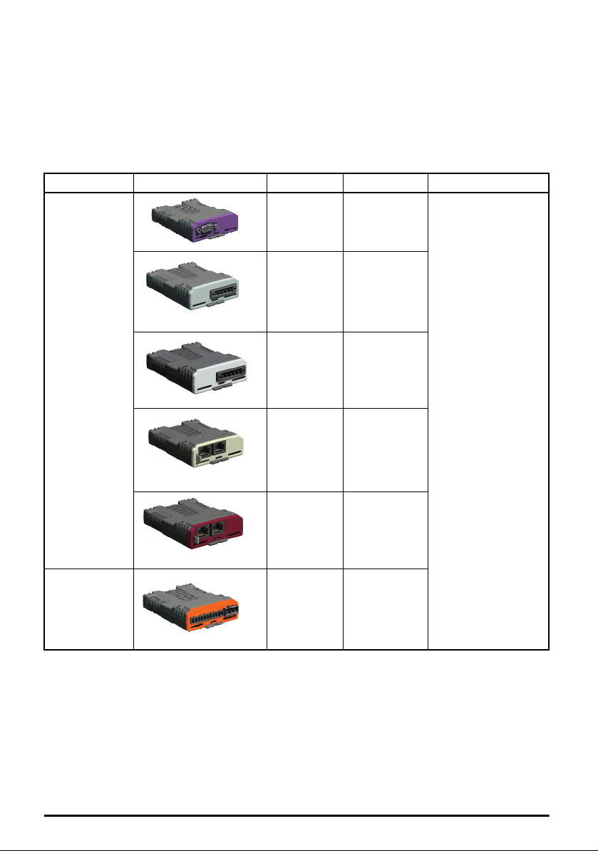
3Options
Table 3-1 System Integration (SI) option module identification
Type Option module Color Name Further details
Purple SI-PROFIBUS
Fieldbus
Automation
(I/O expansion)
Medium
Grey
Light Grey SI-CANopen
Beige SI-Ethernet
Brown Red SI-EtherCAT
Orange SI-I/O
SI-DeviceNet
See relevant option
module User Guide
Unidrive M200/201 Control Quick Start Guide 7
Issue Number: 2
Page 8
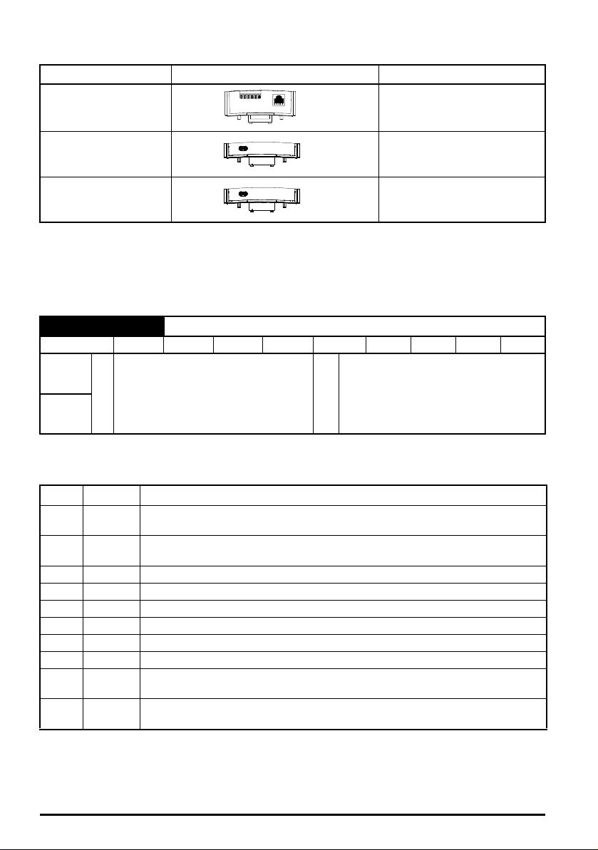
Table 3-2 Adaptor Interface (AI) option module identification
Type Option module Name
Communications AI-485 Adaptor
Backup AI-Backup Adaptor
Backup AI-SMART Adaptor
4 Control connections
For information on the default control connections, refer to the back cover of this guide. The
functionality of the control connections change depending on the setting of Pr 00.005.
4.1 Control terminal configurations and wiring
00.005 Drive Configuration
RW Txt PT US
OL
RFC-A
* With Unidrive M201, the default is Pad (5). The setting of Pr 00.005 automatically sets the drive
configuration.
Value Text Description
0AV
1AI
2AV.Pr
3 AI.Pr
4Preset
5Pad
6 Pad.Ref
7E.Pot
8 torque
9Pid
Defaults are loaded before drive configuration changes are made.
Action will only occur if the drive is inactive, not in UU state and no User Actions are running.
Otherwise, the parameter will return to its pre altered value on exit from edit mode. All parameters
are saved if this parameter changes.
AV (0), AI (1), AV.Pr (2), AI.Pr (3),
Preset (4), Pad (5), Pad.Ref (6),
Ú
E.Pot (7), torque (8), Pid (9)
Analog input 1 (voltage) Analog input 2 (voltage) selected by terminal
(Local/Remote)
Analog input 1 (current) or Analog input 2 (voltage) selected by terminal
(Local/Remote)
Analog input 1 (voltage) or 3 presets selected by terminal
Analog input 1 (current) or 3 presets selected by terminal
Four presets selected by terminal
Keypad reference
Keypad reference with terminal control
Electronic Potentiometer
Torque mode, Analog input 1 (current frequency reference) or Analog input 2
(voltage torque reference) selected by terminal
PID mode, Analog input 1 (current feedback source) and Analog input 2
(voltage reference source)
Ö
AV (0)*
8 Unidrive M200/201 Control Quick Start Guide
Issue Number: 2
Page 9
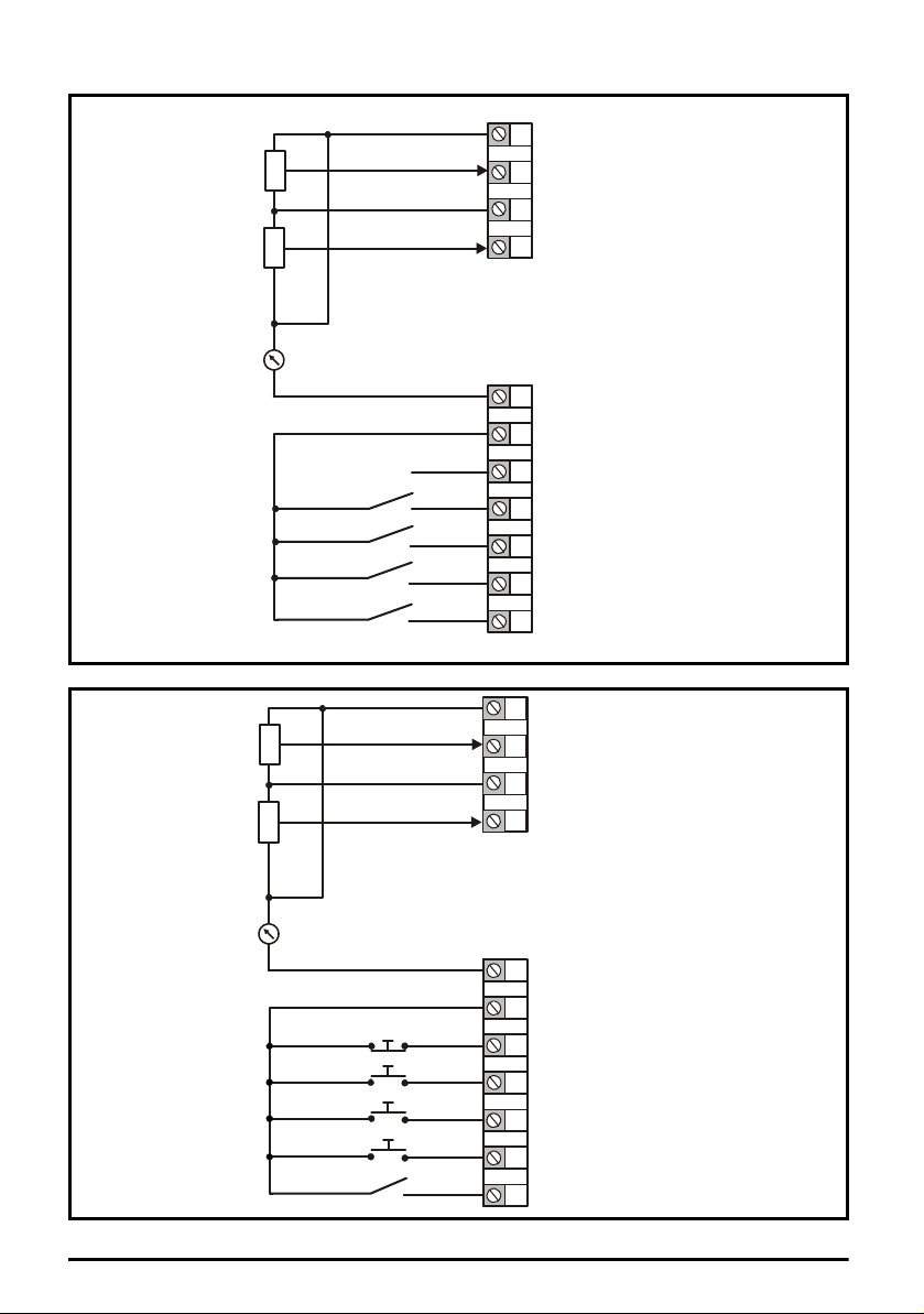
Figure 4-1 Pr 00.005 = AV (50 Hz)
1
2
4
0V
Voltage speed reference
Voltage speed reference
input (AI 2)
input (AI 1)
5
+ 10 V output
7
9
10
Digital output
(zero frequency)
Drive enable
11
12
13
14
Run reverse
Run forward
Analog output 1
(motor frequency)
Analog input 1/
input 2 select
+ 24 V output
10k
10k
1
2
4
0V
Voltage speed reference
Voltage speed reference
input (AI 2)
input (AI 1)
5
+ 10 V output
7
9
10
Digital output
(zero frequency)
Not stop
11
12
13
14
Jog forward
Run
Analog output 1
(motor frequency)
Analog input 1/
input 2 select
+ 24 V output
10k
10k
Figure 4-2 Pr 00.005 = AV (60 Hz)
Unidrive M200/201 Control Quick Start Guide 9
Issue Number: 2
Page 10
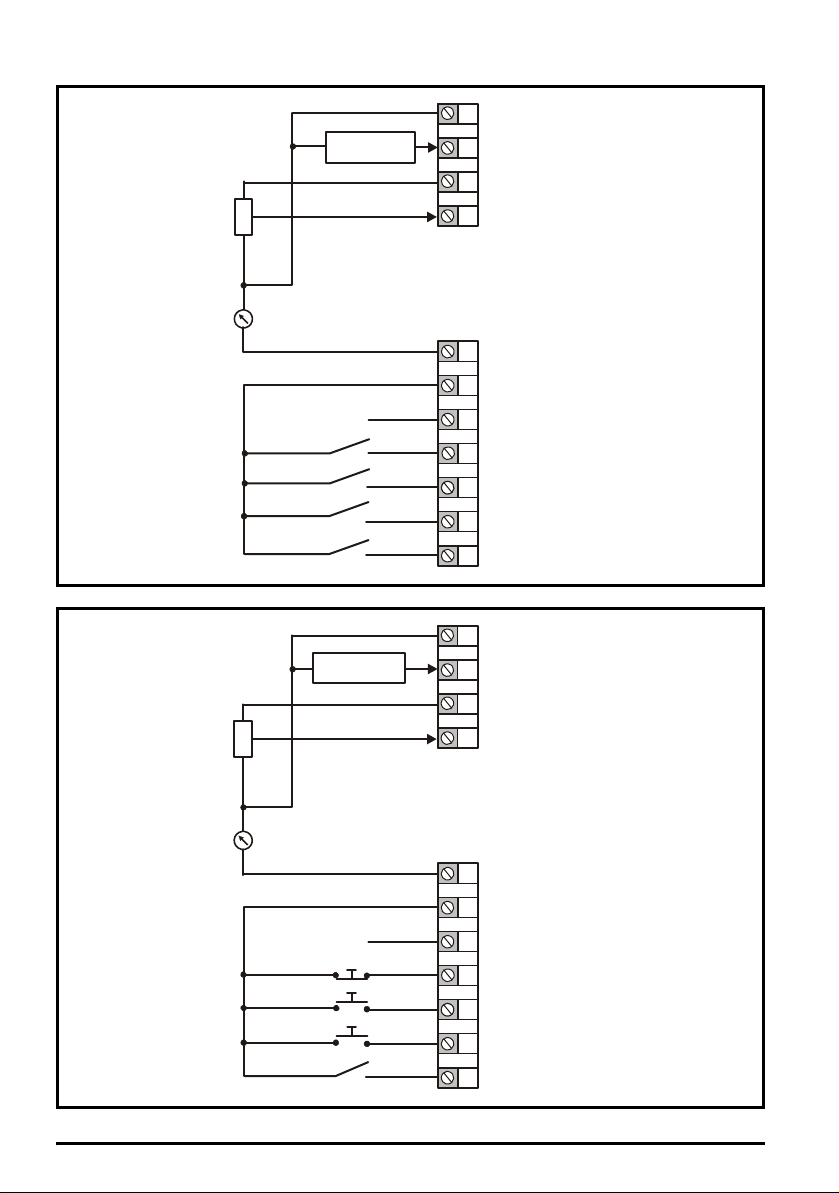
Figure 4-3 Pr 00.005 = AI (50 Hz)
1
2
4
0V
Current speed reference
Current speed
reference input
Voltage speed reference
input (AI 2)
input (AI 1)
5
+ 10 V output
7
9
10
Digital output
(zero frequency)
Drive enable
11
12
13
14
Run reverse
Run forward
Analog output 1
(motor frequency)
Analog input 1/
input 2 select
+ 24 V output
10k
1
2
4
0V
Current speed
reference input
Current speed reference
input (AI 1)
Voltage speed reference
input (AI 2)
5
+ 10 V output
7
9
10
Digital output
(zero frequency)
Not stop
11
12
13
14
Jog forward
Run
Analog output 1
(motor frequency)
Analog input 1/
input 2 select
+ 24 V output
10k
Figure 4-4 Pr 00.005 = AI (60 Hz)
10 Unidrive M200/201 Control Quick Start Guide
Issue Number: 2
Page 11
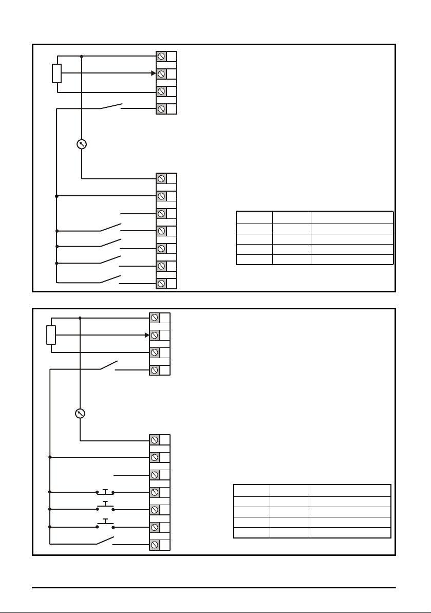
Figure 4-5 Pr 00.005 = AV.Pr (50 Hz)
1
2
4
0V
Voltage speed reference
Reference select
input (AI 1)
5
+ 10 V output
7
9
10
Digital output
(zero frequency)
Drive enable
11
12
13
14
Run reverse
Run forward
Analog output 1
(motor frequency)
Reference select
+ 24 V output
10k
Terminal 5 Terminal 14 Reference selected
0 0 Analog reference 1*
0 1 Preset speed 2*
1 0 Preset speed 3*
1 1 Preset speed 4*
1
2
4
0V
Voltage speed reference
input (AI 1)
Reference select
5
+ 10 V output
7
9
10
Digital output
(zero frequency)
Not stop
11
12
13
14
Jog forward
Run
Analog output 1
(motor frequency)
Reference select
+ 24 V output
10k
Terminal 5 Terminal 14 Reference selected
0 0 Analog reference 1*
0 1 Preset speed 2*
1 0 Preset speed 3*
1 1 Preset speed 4*
Figure 4-6 Pr 00.005 = AV.Pr (60 Hz)
* Refer to the Drive User Guide.
Unidrive M200/201 Control Quick Start Guide 11
Issue Number: 2
Page 12
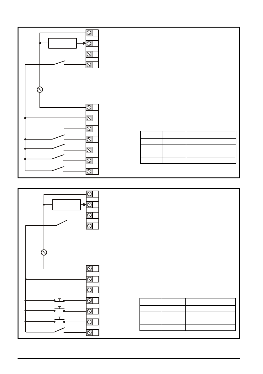
Figure 4-7 Pr 00.005 = AI.Pr (50 Hz)
1
2
4
0V
Current speed
reference input
Current speed
reference input (AI 1)
Reference select
Reference select
5
+ 10 V output
7
9
10
Digital output
(zero frequency)
Drive enable
11
12
13
14
Run reverse
Run forward
Analog output 1
(motor frequency)
+ 24 V output
Terminal 5 Terminal 14 Reference selected
0 0 Analog reference 1*
0 1 Preset speed 2*
1 0 Preset speed 3*
1 1 Preset speed 4*
1
2
4
0V
Current speed reference
input (AI 1)
Reference select
5
+ 10 V output
7
9
10
Digital output
(zero frequency)
Not stop
11
12
13
14
Jog forward
Run
Analog output 1
(motor frequency)
Reference select
+ 24 V output
Current speed
reference input
Terminal 5 Terminal 14 Reference selected
0 0 Analog reference 1*
0 1 Preset speed 2*
1 0 Preset speed 3*
1 1 Preset speed 4*
Figure 4-8 Pr 00.005 = AI.Pr (60 Hz)
* Refer to the Drive User Guide.
12 Unidrive M200/201 Control Quick Start Guide
Issue Number: 2
Page 13
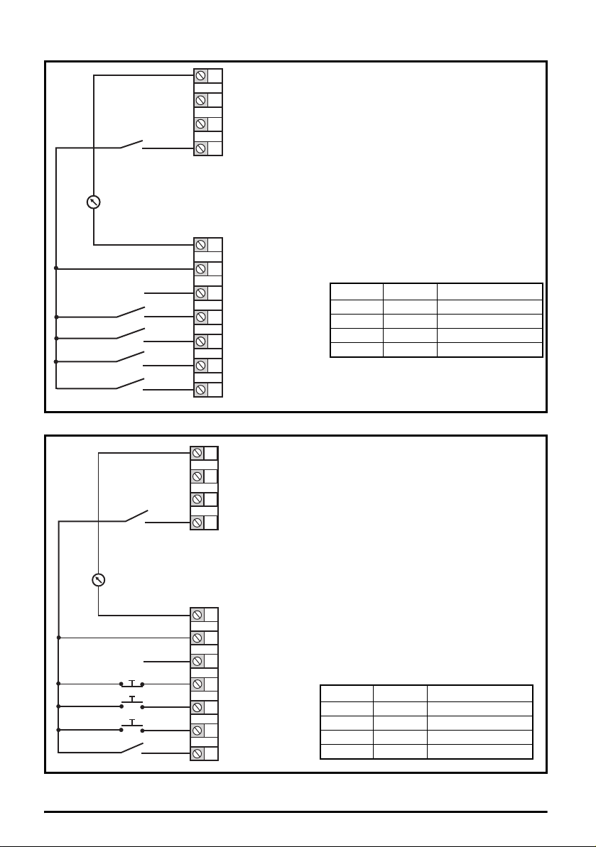
Figure 4-9 Pr 00.005 = Preset (50 Hz)
Terminal 5 Terminal 14 Reference selected
0 0 Preset speed 1*
0 1 Preset speed 2*
1 0 Preset speed 3*
1 1 Preset speed 4*
1
2
4
0V
Voltage speed reference
Reference select
Reference select
input (AI 1)
5
+ 10 V output
7
9
10
Digital output
(zero frequency)
Drive enable
11
12
13
14
Run reverse
Run forward
Analog output 1
(motor frequency)
+ 24 V output
Terminal 5 Terminal 14 Reference selected
0 0 Preset speed 1*
0 1 Preset speed 2*
1 0 Preset speed 3*
1 1 Preset speed 4*
1
2
4
0V
Voltage speed reference
input (AI 1)
Reference select
5
+ 10 V output
7
9
10
Digital output
(zero frequency)
Not stop
11
12
13
14
Jog forward
Run
Analog output 1
(motor frequency)
Reference select
+ 24 V output
Figure 4-10 Pr 00.005 = Preset (60 Hz)
* Refer to the Drive User Guide.
Unidrive M200/201 Control Quick Start Guide 13
Issue Number: 2
Page 14
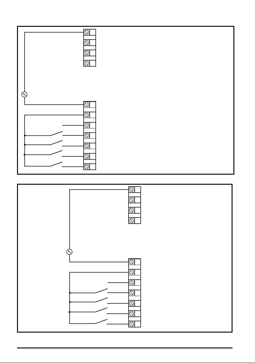
Figure 4-11 Pr 00.005 = Pad (50 Hz & 60 Hz)
When Pr 00.005 is set to Pad, to run in
reverse:
Set Pr 00.017 to On
The keypad reference can now be set to a
negative frequency to run the motor in the
reverse direction
.
1
2
4
0V
Voltage speed reference
Voltage speed reference
input (AI 2)
input (AI 1)
5
+ 10 V output
7
9
10
Digital output
(zero frequency)
Drive enable
11
12
13
14
Run reverse
Run forward
Analog output 1
(motor frequency)
Analog input 1/
input 2 select
+ 24 V output
1
2
4
0V
Voltage speed reference
Voltage speed reference
input (AI 2)
input (AI 1)
5
+ 10 V output
7
9
10
Digital output
(zero frequency)
Drive enable
11
12
13
14
Run reverse
Run forward
Analog output 1
(motor frequency)
Analog input 1/
input 2 select
+ 24 V output
Figure 4-12 Pr 00.005 = Pad.Ref (50 Hz & 60 Hz)
14 Unidrive M200/201 Control Quick Start Guide
Issue Number: 2
Page 15
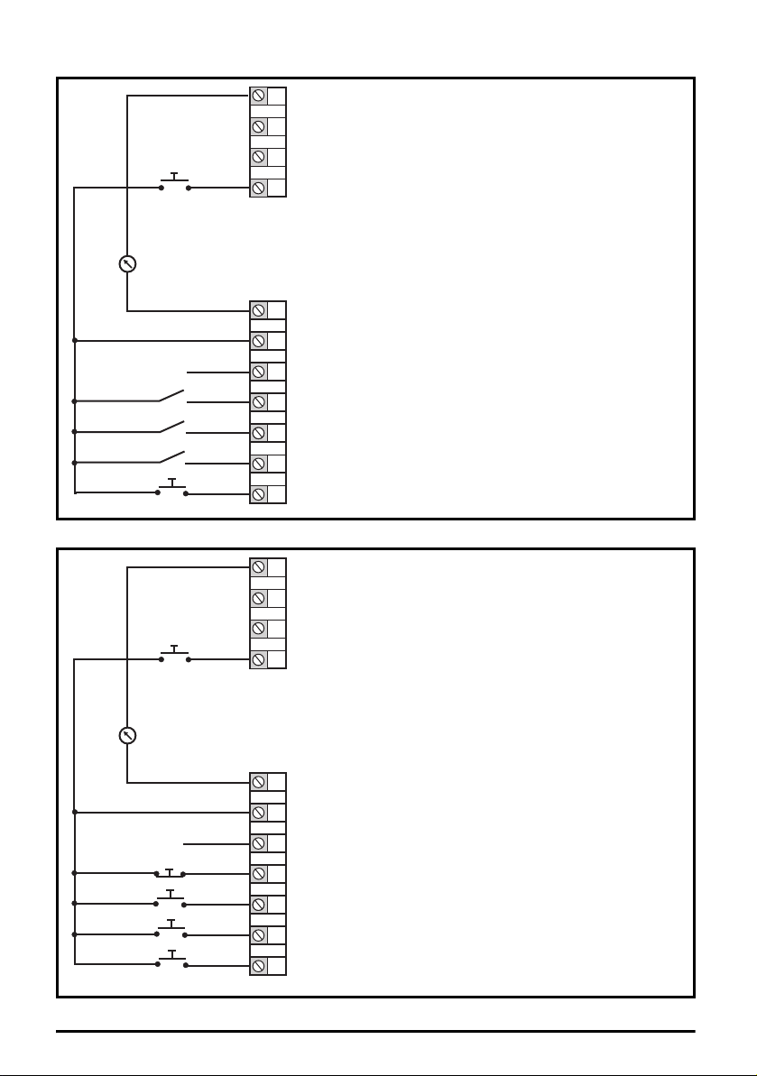
Figure 4-13 Pr 00.005 = E.Pot (50 Hz)
When Pr 00.005 is set to E.Pot, the following
parameters may need to be adjusted:
• Motorized pot up/down rate (s/100 %)
• Motorized pot bipolar select (0 = unipolar, 1 =
bipolar)
• Motorized pot mode: 0 = zero at power-up, 1 = last
value at power-up, 2 = zero at power-up and only
change when the drive is running,
3 = last value at power-up and only change when
drive is running, 4 = zero at power-up and drive
disabled, only change when the drive is running.
1
2
4
0V
Voltage speed reference
input (AI 1)
DOWN
5
+ 10 V output
7
9
10
Digital output
(zero frequency)
Drive enable
11
12
13
14
Run reverse
Run forward
Analog output 1
(motor frequency)
UP
+ 24 V output
When Pr 00.005 is set to E.Pot, the following
parameters may need to be adjusted:
• Motorized pot up/down rate (s/100 %)
• Motorized pot bipolar select
(0 = unipolar, 1 = bipolar)
• Motorized pot mode: 0 = zero at power-up, 1 = last
value at power-up, 2 = zero at power-up and only
change when the drive is running,
3 = last value at power-up and only chan ge when
drive is running, 4 = zero at power-up and drive
disabled, only change when the drive is running.
1
2
4
0V
Voltage speed reference
input (AI 1)
DOWN
5
+ 10 V output
7
9
10
Digital output
(zero frequency)
Not stop
11
12
13
14
Jog forward
Run
Analog output 1
(motor frequency)
UP
+ 24 V output
Figure 4-14 Pr 00.005 = E.Pot (60 Hz)
Unidrive M200/201 Control Quick Start Guide 15
Issue Number: 2
Page 16

Figure 4-15 Pr 00.005 = torque (50 Hz)
1
2
4
0V
Current speed
reference input
Current speed reference
input (AI 1)
Torque reference
input (AI 2)
5
+ 10 V output
7
9
10
Digital output
(zero frequency)
Drive enable
11
12
13
14
Run reverse
Run forward
Analog output 1
(motor frequency)
Torque mode
select
+ 24 V output
10k
When torque mode is selected and
the drive is connected to an
unloaded motor, the motor speed
may increase rapidly to the
maximum speed (Pr 00.002 +10 %)
WARNI NG
1
2
4
0V
Current speed
reference input
Current speed reference
input (AI 1)
Torque reference
input (AI 2)
5
+ 10 V output
7
9
10
Digital output
(zero frequency)
Not stop
11
12
13
14
Jog forward
Run
Analog output 1
(motor frequency)
Torque mode
select
+ 24 V output
10k
When torque mode is selected and
the drive is connected to an
unloaded motor, the motor speed
may increase rapidly to the
maximum speed (Pr 00.002 +10 %)
WARNIN G
Figure 4-16 Pr 00.005 = torque (60 Hz)
16 Unidrive M200/201 Control Quick Start Guide
Issue Number: 2
Page 17

Figure 4-17 Pr 00.005 = Pid (50 Hz)
1
2
4
0V
4 - 20 mA PID
feedback input
PID feedback
input (AI 1)
PID reference
input (AI 2)
5
+ 10 V output
7
9
10
Digital output
(zero frequency)
Drive enable
11
12
13
14
Run reverse
Run forward
Analog output 1
(motor frequency)
PID enable
+ 24 V output
0-10 V PID
Reference input
When Pr 00.005 is set to Pid, the following
parameters may need to be adjusted:
• PID proportional gain*
• PID integral gain*
• PID feedback invert*
• PID output upper limit (%)*
• PID output lower limit (%)*
1
2
4
0V
0-10 V PID
Reference input
4 - 20 mA PID
feedback input
PID feedback
input (AI 1)
PID reference
input (AI 2)
5
+ 10 V output
7
9
10
Digital output
(zero frequency)
Not stop
11
12
13
14
Jog forward
Run
Analog output 1
(motor frequency)
PID enable
+ 24 V output
When Pr 00.005 is set to Pid, the following
parameters may need to be adjusted:
• PID proportional gain*
• PID integral gain*
• PID feedback invert*
• PID output upper limit (%)*
• PID output lower limit (%)*
Figure 4-18 Pr 00.005 = Pid (60 Hz)
* Refer to the Drive User Guide.
Unidrive M200/201 Control Quick Start Guide 17
Issue Number: 2
Page 18

5 Keypad and display
1
2
3
4
5
6
VAHz rpm %
1
V A Hz rpm %
7
The keypad and display provide information to the user regarding the operating status of the drive
and trip codes, and provide the means for changing parameters, stopping and starting the drive, and
the ability to perform a drive reset.
Figure 5-1 Unidrive M200 keypad detail Figure 5-2 Unidrive M201 keypad detail
(1) The Enter button is used to enter parameter view or edit mode, or to accept a parameter edit.
(2 / 5) The Navigation keys can be used to select individual parameters or to edit parameter values.
(3) The Stop / Reset key is used to stop and reset the drive in keypad mode. It can also be used to
reset the drive in terminal mode.
(4) The Start key is used to start the drive in keypad mode.
(6) The Escape key is used to exit from the parameter edit / view mode.
(7) The Speed ref pot is used to control the speed reference in keypad mode (only on Unidrive
M201).
Table 5-1 Status indications
String Description
The drive is inhibited and cannot be run. The Drive Enable signal
inh
is not applied to the drive enable terminal or is set to 0. The other
conditions that can prevent the drive from enabling are shown as
bits in Enable Conditions.
rdy
The drive is ready to run. The drive enable is active, but the drive
inverter is not active because the final drive run is not active
StoP The drive is stopped / holding zero speed. Enabled
S.Loss Supply loss condition has been detected Enabled
dc inj The drive is applying dc injection braking Enabled
Er
UV
18 Unidrive M200/201 Control Quick Start Guide
The drive has tripped and no longer controlling the motor. The trip
code appears on the display.
The drive is in the under voltage state either in low voltage or high
voltage mode.
Issue Number: 2
Drive output
stage
Disabled
Disabled
Disabled
Disabled
Page 19

5.1 Saving parameters
When changing a parameter in Menu 0, the new value is saved when pressing the Enter button
to return to parameter view mode from parameter edit mode.
If parameters have been changed in the advanced menus, then the change will not be saved
automatically. A save function must be carried out.
Procedure
1. Select ‘Save'* in Pr mm.000 (alternatively enter a value of 1001* in Pr mm.000)
2. Either:
• Press the red reset button
• Carry out a drive reset through serial communications by setting Pr 10.038 to 100
* If the drive is in the under voltage state (i.e. when the AI-Backup adaptor terminals are being
supplied from a +24 Vdc supply) a value of 1001 must be entered into Pr mm.000 to perform a save
function.
5.2 Restoring parameter defaults
Restoring parameter defaults by this method saves the default values in the drives memory. User
security status (00.010) and User security code (00.025) are not affected by this procedure).
Procedure
1. Ensure the drive is not enabled, i.e. terminal 11 is open or is OFF (0)
2. Select 'Def.50’ or 'Def.60' in Pr mm.000. (alternatively, enter 1233 (50 Hz settings) or 1244 (60
Hz settings) in Pr mm.000).
3. Either:
• Press the red reset button
• Carry out a drive reset through serial communications by setting Pr 10.038 to 100
Unidrive M200/201 Control Quick Start Guide 19
Issue Number: 2
Page 20

6 Basic parameters (Menu 0)
Menu 0 is used to bring together various commonly used parameters for basic easy set up of the
drive. All the parameters in Menu 0 appear in other menus in the drive (denoted by {…}). Menus 22
can be used to configure the parameters in Menu 0.
6.1 Menu 0: Basic parameters
(Ú) Default (Ö)
Parameter
Minimum Reference
00.001
Clamp
Maximum Reference
00.002
Clamp
00.003 Acceleration Rate 1 ±VM_ACCEL_RATE s/100 Hz 5.0 s/100 Hz RW Num US
00.004 Deceleration Rate 1 ±VM_ACCEL_RATE s/100 Hz 10.0 s/100 Hz RW Num US
00.005 Drive Configuration
00.006 Motor Rated Current 0.00 to VM_RATED_CURRENT A
00.007 Motor Rated Speed 0.0 to 80000.0 rpm
00.008 Motor Rated Voltage 0 to VM_AC_VOLTAGE_SET V
Motor Rated Power
00.009
Factor
00.010 User Security Status
00.015 Jog Reference 0.00 to 300.00 Hz 1.50 Hz RW Num US
00.016 Analog Input 1 Mode
Bipolar Reference
00.017
Enable
00.018 Preset Reference 1 ±VM_SPEED_FREQ_REF Hz 0.00 Hz RW Num US
00.025 User Security Code 0 to 9999 0 RW Num ND NC PT US
Power-up Keypad
00.027
Control Mode
Reference
00.028 Ramp Mode Select
00.029 Ramp Enable Off (0) or On (1) On (1) RW Bit US
00.030 Parameter Cloning
00.031 Stop Mode
Dynamic V to F
00.032
Select / Flux
Optimization Select
±VM_NEGATIVE_REF_CLAMP1 Hz 0.00 Hz RW Num US
4-20.H (-2), 20-4.H (-1), 0-20 (0), 20-
Range
OL RFC-A OL RFC-A
±VM_POSITIVE_REF_CLAMP Hz
AV (0), AI (1), AV.Pr (2), AI.Pr (3),
Preset (4), Pad (5), Pad.Ref (6),
E.Pot (7), torque (8), Pid (9)
0.00 to 1.00 0.85 RW Num RA US
LEVEL.0 (0), ALL (1), r.only.0 (2),
r.only.A (3), Status (4), no.acc(5)
4-20.S (-6), 20-4.S (-5),
4-20.L (-4), 20-4.L (-3),
0 (1), 4-20.tr (2), 20-4.tr (3),
4-20 (4), 20-4 (5), Volt (6)
Off (0) or On (1) Off (0) RW Bit US
Reset (0), Last (1), Preset (2) Reset (0) RW Txt US
Fast (0), Std (1), Std.bst (2),
Fst.bst (3)
None (0), rEAd (1), Prog (2),
Auto (3), boot (4)
CoASt (0), rP (1), rP.dc I (2),
dc I (3), td.dc I (4), dis (5),
No.rP (6)
0 to 1 0 RW Num US
50 Hz default: 50.00 Hz
60 Hz default: 60.00 Hz
AV (0)* RW Txt PT US
Maximum Heavy Duty
Rating A
50 Hz default:
1500.0 rpm
60 Hz default:
1800.0 rpm
400 V drive 50 Hz: 400 V
400 V drive 60 Hz: 460 V
50 Hz default:
1450.0 rpm
60 Hz default:
1750.0 rpm
110 V drive: 230 V
200 V drive: 230 V
575 V drive: 575 V
690 V drive: 690 V
LEVEL.0 (0) RW Num ND NC PT
Volt (6) RW Txt US
Std ( 1) RW Txt US
None (0) RW Txt NC US
rp (1) RW Txt US
RW N um US
RW N um RA US
RW N um US
RW N um RA US
Typ e
20 Unidrive M200/201 Control Quick Start Guide
Issue Number: 2
Page 21

(Ú) Default (Ö)
Parameter
Catch A Spinning
00.033
Motor
00.034 Digital Input 5 Mode
Digital Output 1
00.035
Control
Analog Output 1
00.036
Control
Maximum Switching
00.037
Frequency
00.038 Autotune 0 to 2 0 to 3 0 RW Num NC US
Motor Rated
00.039
Frequency
Number of Motor
00.040
Poles**
Ur.S (0), Ur (1), Fd
00.041 Control Mode
Low Frequency
00.042
Voltage Boost
00.043 Serial Baud Rate
00.044 Serial Address 1 to 247 1 RW Num US
Reset Serial
00.045
Communications
Brake Controller
00.046
Upper Current
Threshold
Brake Controller
00.047
Lower Current
Threshold
Brake Controller
00.048
Brake Release
Frequency
Brake Controller
00.049
Brake Apply
Frequency
Brake Controller
00.050
Brake Delay
Brake Controller
00.051
Post-brake Release
Delay
Brake Controller
00.053
Initial Direction
Brake Controller
00.054
Brake Apply Through
Zero Threshold
Brake Controller
00.055
Enable
Frequency Controller
00.065
Proportional Gain
Kp1
Frequency Controller
00.066
Integral Gain Ki1
Range
OL RFC-A OL RFC-A
dis (0), Enable (1), Fr.Only (2),
Rv.Only (3)
Input (0), th.Sct (1), th (2),
th.Notr (3), Fr (4)
0 to 21 0 RW Num US
0 to 14 0 RW Txt US
0.667 (0), 1 (1), 2
(2), 3 (3), 4 (4), 6
(5), 8 (6), 12 (7),
16 (8) kHz
0.00 to VM_SPEED_FREQ_REF_
UNIPOLAR Hz
Auto (0) to 32 (16) Auto 0 RW Num US
(2), Ur.Auto (3),
Ur.I (4), SrE (5),
Fd.tap (6)
300 (0), 600 (1), 1200 (2),
2400 (3), 4800 (4), 9600 (5),
19200 (6), 38400 (7), 57600 (8),
76800 (9), 115200 (10)
Off (0) or On (1) Off (0) RW ND NC US
0.00 to 20.00 Hz 1.00 Hz RW Num US
0.00 to 20.00 Hz 2.00 Hz RW Num US
Ref (0), For (1), Rev (2) Ref (0) RW Txt US
0.00 to 25.00 Hz 0.00 Hz RW Num US
dis (0), Relay (1), dig IO (2),
2 (2), 3 (3),
4 (4), 6 (5),
8 (6), 12 (7),
16 (8) kHz
0.0 to 25.0 % 3.0 % RW Num US
0 to 200 % 50 % RW Num US
0 to 200 % 10 % RW Num US
0.0 to 25.0 s 1.0 s RW Num US
0.0 to 25.0 s 1.0 s RW Num US
User (3)
0.000 to
200.000 s/rad
0.00 to
655.35 s2/rad
dis (0) RW Txt US
Input (0) RW Txt US
3 (3) kHz RW Txt US
50Hz: 50.00 Hz
60Hz: 60.00 Hz
Ur.I (4) RW Txt US
19200 (6) RW Txt US
dis (0) RW Txt US
0.100 s/rad RW Num US
0.10 s2/rad
RW Num US
RW Num US
Typ e
Unidrive M200/201 Control Quick Start Guide 21
Issue Number: 2
Page 22

(Ú) Default (Ö)
Parameter
Sensorless Mode
00.067
Filter
00.069 Spin Start Boost 0.0 to 10.0 1.0 RW Num US
Action on Trip
00.076
Detection
Maximum Heavy
00.077
Duty Current Rating
00.078 Software Version 0 to 999999 RO Num ND NC PT
00.079 User Drive Mode OPEn.LP (1), RFC-A (2) OPEn.LP (1) RFC-A (2) RW Txt ND NC PT US
Range
OL RFC-A OL RFC-A
4 (0), 5 (1), 6
(2), 8 (3), 12 (4),
20 (5) ms
0 to 31 0 RW Num ND NC PT US
0.00 to 9999.99 A RO Num ND NC PT
4 (0) ms RW Txt US
Typ e
* With Unidrive M201, the default is Pad (5).
** If this parameter is read via serial communications, it will show pole pairs.
RW
ND
Read /
Write
No
default
value
RO
NC
Read
only
Not
copied
Num
PT
Number
parameter
Protected
parameter
Bit
RA
Bit
parameter
Rating
dependent
Txt Text string Bin
US User save PS
Binary
parameter
Power-down
save
FI Filtered
DE Destination
22 Unidrive M200/201 Control Quick Start Guide
Issue Number: 2
Page 23

Unidrive M200/201 Control Quick Start Guide 23
Issue Number: 2
Page 24

Figure 6-1 Menu 0 logic diagram
2
5
Analog reference
Keypad reference
00.XXX
00.XXX
Key
Read-write
(RW)
parameter
Read-only
(RO)
parameter
Input
terminals
Output
terminals
X
X
X
X
The parameters are all shown in their default settings
00.018
Preset
Reference 1
Preset frequency
reference
14
0
5
00.017
Bipolar
Analog input 1
Analog input
1 mode
Analog input 1/
input 2 select
Analog input 2
Reference
Enable
AV
Pr
Pad
Pad.Ref
E. Pot
tor
Pid
678
9
01.015
00.016
Pr
set
01.050
>
1
01.050
00.005
Drive
Configuration
AI
AV.Pr
AI.Pr
1
2
3
4
24 Unidrive M200/201 Control Quick Start Guide
Issue Number: 2
Page 25

Frequency
Controller
Integral
Gain Ki 1
Frequency
Controller
Proportional
Gain Kp 1
Motor
Rpm
00.033
00.065
00.066
Frequency
Controller
Differential
Feedback
Gain Kd 1
RFC-A Frequency -loop
PID
gains
7
10
AT ZERO FREQUENCY
Power
Factor
Rated
Voltage
Rated Speed
Rated
Current
00.006 ~ 00.009
Motor
parameters
Power stage
Control mode
Dynamic
V/f
Select
Low Frequency
Voltage Boost
OL>
Motor-voltage
control
Estimated
Motor
Speed
_+_
+
UVW
Resistor
optional
Drive
RUN
REVERSE
RUN
FORWARD
Minimum
Reference
Reference
Clamp
00.001
00.002
12 13
Ramps
Acceleration
Rate 1
Deceleration
Rate 1
Ramp Mode
Select
00.003
00.004
00.028
RFC-A mode only
00.029
Maximum
Clamp
Ramp
Enable
Analog output Digital outp ut
00.037
05.001
Maximum Switching
Frequency
Output Frequency
04.011
Torque Mode
Selector
RFC-A
Torque
Producing
Current
Current
Magnitude
Magnetising
Current
+BR_
RFC-A>
OL,
FREQUENCY
RFC-A>
04.002
04.001
00.041
00.042
05.004
05.004
03.012
00.032
L3L2L1
Unidrive M200/201 Control Quick Start Guide 25
Issue Number: 2
Page 26

6.2 Unidrive M200/201 parameter descriptions
Key:
Read /
RW
Write
No
ND
default
value
00.001 {01.007} Minimum Reference Clamp
RW Num US
OL
RFC-A
Set Pr 00.001 at the required minimum output frequency of the drive for both directions of rotation.
The drive speed reference is scaled between Pr 00.001 and Pr 00.002. Pr 00.001 is a nominal value;
slip compensation may cause the actual frequency to be higher. When the drive is jogging, Pr 00.001
has no effect.
00.002 {01.006} Maximum Reference Clamp
RW Num US
OL
RFC-A
Set Pr 00.002 at the required maximum output frequency for both directions of rotation. The drive
speed reference is scaled between Pr 00.001 and Pr 00.002. Pr 00.002 is a nominal value; slip
compensation may cause the actual frequency to be higher. The drive has additional over-speed
protection.
Read
RO
only
Not
NC
copied
±VM_NEGATIVE_REF_CLAMP1 Hz
Ú
±VM_POSITIVE_REF_CLAMP Hz
Ú
Num
PT
Number
parameter
Protected
parameter
Bit
RA
Bit
parameter
Rating
dependent
Txt Text string Bin
US User save PS
Ö
Ö
Binary
parameter
Power-down
save
FI Filtered
DE Destination
0.00 Hz
50.0 Hz default: 50.00 Hz
60.0 Hz default: 60.00 Hz
00.003 {02.011} Acceleration Rate 1
RW Num US
OL
RFC-A
±VM_ACCEL_RATE s/100 Hz
Ú
Ö
5.0 s/100 Hz
Set Pr 00.003 at the required rate of acceleration. Note that larger values produce lower
acceleration. The rate applies in both directions of rotation.
26 Unidrive M200/201 Control Quick Start Guide
Issue Number: 2
Page 27

00.004 {02.021} Deceleration Rate 1
NOTE
NOTE
RW Num US
OL
RFC-A
Set Pr 00.004 at the required rate of deceleration. Note that larger values produce lower
deceleration. The rate applies in both directions of rotation.
00.005 {11.034} Drive Configuration
RW Txt PT US
OL
* With Unidrive M201, the default is Pad (5).
Use Pr 00.005 to select the required frequency/speed reference as follows:
Value Text Description
0AV
1AI
2AV.Pr
3 AI.Pr
4Preset
5Pad
6 Pad.Ref
7E.Pot
8 torque
9Pid
±VM_ACCEL_RATE s/100 Hz
Ú
AV (0), AI (1), AV.Pr (2), AI.Pr (3),
Preset (4), Pad (5), Pad.Ref (6),
Ú
E.Pot (7), torque (8), Pid (9)
Analog input 1 (voltage) Analog input 2 (voltage) selected by terminal
(Local/Remote)
Analog input 1 (current) or Analog input 2 (voltage) selected by terminal
(Local/Remote)
Analog input 1 (voltage) or 3 presets selected by terminal
Analog input 1 (current) or 3 presets selected by terminal
Four presets selected by terminal
Keypad reference
Keypad reference with terminal control
Electronic Potentiometer
Torque mode, Analog input 1 (current frequency reference) or Analog input 2
(voltage torque reference) selected by terminal
PID mode, Analog input 1 (current feedback source) and Analog input 2
(voltage reference source)
Ö
Ö
10.0 s/100 Hz
AV ( 0 ) *
A change to Pr 00.005 is set by pressing the MODE key on exit from parameter edit mode.
The drive must be disabled, stopped or tripped for a change to take place. If Pr 00.005 is
changed while the drive is running, when the MODE key is pressed on exit from parameter
edit mode, Pr 00.005 will change back to its previous value.
When the setting of Pr 00.005 is changed, the appropriate drive configuration parameters
are set back to their default values.
Unidrive M200/201 Control Quick Start Guide 27
Issue Number: 2
Page 28

00.006 {05.007} Motor Rated Current
RW Num RA US
OL
RFC-A
The rated current parameter must be set to the maximum continuous current of the motor (taken
from the name plate). The motor rated current is used in the following:
• Current limits
• Motor thermal overload protection
• Vector mode voltage control
• Slip compensation (see Enable Slip Compensation)
• Dynamic V/F control
00.007 {05.008} Motor Rated Speed
RW Num US
OL
RFC-A
Set to the rated speed of the motor (taken from the motor name plate). The motor rated speed is
used to calculate the correct slip speed for the motor.
00.008 {05.009} Motor Rated Voltage
RW Num RA US
OL
RFC-A
0.00 to VM_RATED_CURRENT A
Ú
Ú
Ú
0.0 to 80000.0 rpm
0 to VM_AC_VOLTAGE_SET V
Ö
Ö
Ö
Maximum Heavy
Duty Rating A
50 Hz default: 1500.0 rpm
60 Hz default: 1800.0 rpm
50 Hz default: 1450.0 rpm
60 Hz default: 1750.0rpm
110 V drive: 230 V
200 V drive: 230 V
400 V drive 50 Hz: 400 V
400 V drive 60 Hz: 460 V
575 V drive: 575 V
690 V drive: 690 V
The Rated Voltage (00.008) and the Rated Frequency (00.039) are used to define the voltage to
frequency characteristic applied to the motor. The Rated Frequency (00.039) is also used in
conjunction with the Motor Rated Speed (00.007) to calculate the rated slip for slip compensation.
00.009 {05.010} Motor Rated Power Factor
RW Num RA US
OL
RFC-A
Enter the motor rated power factor cos
The drive can measure the motor rated power factor by performing a rotating autotune (see Autotune
(Pr 00.038).
Ú
0.00 to 1.00
Ö
ϕ (taken from the motor name plate).
0.85
28 Unidrive M200/201 Control Quick Start Guide
Issue Number: 2
Page 29

00.010 {11.044} User Security Status
RW Num ND NC PT US
OL
RFC-A
LEVEL.0 (0), ALL (1), r.only.0 (2),
Ú
r.only.A (3), Status (4), no.Acc (5)
Ö
LEVEL.0 (0)
This parameter controls access via the drive keypad as follows:
Value Text Function
0 Menu 0 (LEVEL.0)
1 All Menus (ALL) All writable parameters are visible and available to be edited.
Read-only Menu 0
2
(r.only.0)
3 Read-only (r.only.A) All parameters are read-only however all menus and parameters are visible.
4 Status Only (Status)
5 No Access (no.Acc)
All writable parameters are available to be edited but only parameters in
Menu 0 are visible.
All parameters are read-only. Access is limited to Menu 0 parameters only.
The keypad remains in status mode and no parameters can be viewed or
edited.
The keypad remains in status mode and no parameters can be viewed or
edited. Drive parameters cannot be accessed via a comms/fieldbus interface
in the drive or any option module.
00.015 {01.005} Jog Reference
RW Num US
OL
RFC-A
Ú
0.00 to 300.00 Hz
Ö
1.50 Hz
Defines the reference when jog is enabled.
Unidrive M200/201 Control Quick Start Guide 29
Issue Number: 2
Page 30

00.016 {07.007} Analog Input 1 Mode
NOTE
NOTE
RW Txt US
4-20.S (-6), 20-4.S (-5), 4-20.L (-4),
OL
Defines the mode of analog input 1.
The table below gives all the possible analog input modes.
Value Text Function
-6 4-20.S Stop on loss
-5 20-4.S Stop on loss
-4 4-20.L 4-20 mA switching to equivalent of 4 mA input current on loss
-3 20-4.L 20-4 mA switching to equivalent of 20 mA input current on loss
-2 4-20.H 4-20 mA hold at level before loss on loss
-1 20-4.H 20-4 mA hold at level before loss on loss
0 0-20 0-20 mA
1 20-0 20-0 mA
2 4-20.tr 4-20 mA trip on loss
3 20-4.tr 20-4 mA trip on loss
4 4-20 4-20 mA no action on loss
5 20-4 20-4 mA no action on loss
6 Volt Voltage
20-4.L (-3), 4-20.H (-2), 20-4.H (-1),
Ú
0-20 (0), 20-0 (1), 4-20.tr (2),
20-4.tr (3), 4-20 (4), 20-4 (5), Volt (6)
In 4-20 mA and 20-4 mA modes loss of input is detected if the current falls below 3 mA.
Ö
Vol t (6 )
If both analog inputs (A1 and A2) are to be set-up as voltage inputs, and if the
potentiometers are supplied from the drive's +10 V rail (terminal T3), they must have a
resistance >4 kΩ each.
00.017 {01.010} Bipolar Reference Enable
RW Bit US
OL
RFC-A
Pr 00.017 determines whether the reference is uni-polar or bi-polar.
See Minimum Reference Clamp (00.001). Allows negative speed reference in keypad mode.
Ú
Off (0) or On (1)
Ö
Off (0)
30 Unidrive M200/201 Control Quick Start Guide
Issue Number: 2
Page 31

00.018 {01.021} Preset Reference 1
RW Num US
OL
RFC-A
If the preset reference has been selected (see Pr 00.005), the speed at which the motor runs is
determined by these parameters.
See Drive Configuration (00.005).
00.025 {11.030} User Security Code
RW Num ND NC PT US
OL
RFC-A
If any number other than 0 is programmed into this parameter, user security can be applied so that
no parameters except Pr 00.010 can be adjusted with the keypad. When this parameter is read via a
keypad it appears as zero. Refer to the Drive User Guide for further information.
00.027 {01.051} Power-up Keypad Control Mode Reference
RW Txt ND NC PT US
OL
RFC-A
±VM_SPEED_FREQ_REF Hz
Ú
Ú
Ú
Reset (0), Last (1), Preset (2)
0-9999
Ö
Ö
Ö
0.00 Hz
0
Reset (0)
Defines which value of keypad control mode reference is displayed at power-up.
Value Text Description
0 Reset Keypad reference is zero
1 Last Keypad reference is the last used value
2 Preset Keypad reference is copied from Preset Reference 1 (00.018)
00.028 {02.004} Ramp Mode Select
RW Txt US
OL
RFC-A
Defines the mode used by the ramp system.
Unidrive M200/201 Control Quick Start Guide 31
Issue Number: 2
Ú
0: Fast ramp
1: Standard ramp
2: Standard ramp with motor voltage boost
3: Fast ramp with motor voltage boost
Fast (0), Std (1), Std.bst (2),
Fst.bst (3)
Ö
Std (1)
Page 32

Fast ramp is linear deceleration at programmed rate, normally used when a braking resistor is
installed.
Standard ramp is controlled deceleration to prevent DC bus over-voltage trips, normally used when
there is no braking resistor installed.
If a high motor voltage mode is selected, deceleration rates can be faster for a given inertia but motor
temperatures will be higher.
00.029 {02.002} Ramp Enable
RW Bit US
OL
RFC-A Off (0) or On (1) On (1)
Setting Pr 00.029 to 0 allows the user to disable the ramps. This is generally used when the drive is
required to closely follow a speed reference which already contains acceleration and deceleration
ramps.
OL
RFC-A
* Only a value of 3 or 4 in this parameter is saved.
If Pr 00.030 is equal to 1 or 2, this value is not transferred to the EEPROM or the drive. If Pr 00.030 is
set to a 3 or 4 the value is transferred.
Parameter string Parameter value Comment
For further information, please refer to Chapter 9 NV Media Card Operation on page 49.
Ú Ö
00.030 {11.042} Parameter Cloning
RW Txt NC US*
None (0), Read (1), Program (2),
Ú
None 0 Inactive
Read 1 Read parameter set from the NV Media Card
Program 2 Programming a parameter set to the NV Media Card
Auto 3 Auto save
Boot 4 Boot mode
Auto (3), Boot (4)
Ö
None (0)
32 Unidrive M200/201 Control Quick Start Guide
Issue Number: 2
Page 33

00.031 {06.001} Stop Mode
RW Txt US
OL
Ú
RFC-A
Defines how the motor is controlled when the run signal is removed from the drive.
Value Text Description
0 Coast Coast stop
1 rp Ramp stop
2 rP.dcI Ramp stop + 1 second dc injection
3 dc I Injection braking stop with detection of zero speed
4 td.dcI Timed injection braking stop
5 Dis Disable
6 No.rP No ramp (RFC-A mode only)
See the Drive User Guide for further information.
00.032 {05.013} Dynamic V To F Select / Flux Optimisation Select
RW Num US
OL
RFC-A
Set to 1 to enable Dynamic V to F mode.
Ú
0: Fixed linear voltage to frequency ratio (constant torque - standard load)
1: Voltage to frequency ratio dependant on load current. This gives a higher motor efficiency.
CoASt (0), rP (1), rP.dc I (2),
dc I (3), td.dc I (4), dis (5)
CoASt (0), rP (1), rP.dc I (2),
dc I (3), td.dc I (4), dis (5), No.rP (6)
0 to 1
Ö
Ö
rP (1)
0
00.033 {06.009} Catch a Spinning Motor
RW Txt US
OL
RFC-A
If the drive is to be configured in fixed boost mode (Pr 00.041 = Fd or SrE) with catch a spinning
motor software enabled, an autotune (see Pr 00.038 on page 36) must be carried out to measure the
motor's stator resistance beforehand. If a stator resistance is not measured, the drive may trip on 0 V
or OI.AC while trying to catch a spinning motor.
Pr 00.033 Text Function
0 Dis Disabled
1 Enable Detect all frequencies
2 Fr.Only Detect positive frequencies only
3 Rv.Only Detect negative frequencies only
Unidrive M200/201 Control Quick Start Guide 33
Issue Number: 2
dis (0), Enable (1), Fr.Only (2),
Ú
Rv.Only (3)
Ö
dis (0)
Page 34

00.034 {08.005} Digital Input 5 Mode
RW Txt US
OL
RFC-A
This parameter selects the function of Digital Input 5.
Value Text Function
0 Input (0) Digital input
1th.Sct (1)
2th (2)
3 th.Notr (3) Temperature measurement input with no trips
4 Fr (4) Frequency input
00.035 {08.091} DO1 Control (terminal 10)
RW Num US
OL
RFC-A
Defines the behaviour of digital output 1.
Value Description
0
1 Drive running signal (RUN)
2 Frequency arrived signal (FAR)
3 Frequency level detection signal (FDT1)
4 Frequency level detection signal (FDT2)
5 Overload detection signal (OL)
6 Power off state (LU)
7 External fault stop (EXT)
8 Frequency upper limit (FHL)
9 Frequency lower limit (FLL)
10 Drive running at zero frequency
14 Drive (RDY)
15 Drive OK
18 Brake release
19 Torque limiting (Valid while the torque is limited by torque limiting value 1/2)
20 Forward or reverse
21 Motor 1 or 2
Input (0), th.Sct (1), th (2), th.Notr
Ú
Ú
User defined by Digital IO1 Source/Destination A, Digital IO2 Source/Destination A,
Relay 1 Output Source A, or Relay 2 Output Source A.
(3), Fr (4)
Temperature measurement input with short circuit detection
(Resistance <50 Ω )
Temperature measurement input without short circuit detection but
with th trip
0-21
Ö
Ö
Input (0)
0
34 Unidrive M200/201 Control Quick Start Guide
Issue Number: 2
Page 35

00.036 {07.055} Analog Output 1 Control
RW Txt US
OL
RFC-A
Defines the functionality of Analog Output 1.
Value Description
OL
RFC-A
Defines the maximum switching frequency that can be used by the drive.
See the Drive User Guide for drive derating data.
Ú
0 User defined by Analog Output 1 Source A
1 Frequency output
2 Frequency reference
3 Motor speed
4 Current Magnitude
6 Torque output
7 Torque current output
8 Voltage output
9 DC bus voltage (0~800 V)
10 Analog Input 1
11 Analog Input 2
12 Power output (0~2 x Pe)
13 Torque limitation
14 Torque reference (0~300 %)
00.037 {05.018} Maximum Switching Frequency
RW Txt US
0.667 (0), 1 (1), 2 (2), 3 (3), 4 (4),
Ú
Pr 00.037 Text Description
0 0.667 667 Hz switching frequency
1 1 1 kHz switching frequency
2 2 2 kHz switching frequency
3 3 3 kHz switching frequency
4 4 4 kHz switching frequency
5 6 6 kHz switching frequency
6 8 8 kHz switching frequency
7 12 12 kHz switching frequency
8 16 16 kHz switching frequency
6 (5), 8 (6), 12 (7), 16 (8) kHz
2 (2), 3 (3), 4 (4), 6 (5), 8 (6), 12 (7),
0 to 14
16 (8) kHz
Ö
Ö
3 (3) kHz
0
Unidrive M200/201 Control Quick Start Guide 35
Issue Number: 2
Page 36

00.038 {05.012} Autotune
WARNING
RW Num NC US
OL
RFC-A 0 to 3
Defines the auto-tune test to be performed.
There are two autotune tests available in open loop mode, a stationary and a rotating test. A rotating
autotune should be used whenever possible so the measured value of power factor of the motor is
used by the drive.
Open Loop and RFC-A:
1. A stationary autotune can be used when the motor is loaded and it is not possible to remove the
2. A rotating autotune should only be used if the motor is unloaded. A rotating autotune first
RFC-A only:
3. This test measures the mechanical characteristic of the motor and load by rotating the motor.
Following the completion of an autotune test the drive will go into the inhibit state. The drive must be
placed into a controlled disable condition before the drive can be made to run at the required
reference. The drive can be put in to a controlled disable condition by setting the Drive Enable to Off
(0) or disabling the drive via the Control Word and Control Word Enable
Ú
load from the motor shaft. To perform a Stationary autotune, set Pr 00.038 to 1,
performs a stationary autotune, as above, then a rotating test is performed in which the motor is
accelerated with currently selected ramps up to a frequency of Rated Frequency (00.039) x 2/3,
and the frequency is maintained at that level for 4 seconds. To perform a Rotating autotune, set
Pr 00.038 to 2.
This test should only be used provided all the basic control parameters have been set-up
correctly. The test measures the motor and load inertia, which can be used in automatic set-up of
the frequency controller gains and in producing a torque feed-forward term. It also measures the
load compensation parameters to cancel resonance effects.
A rotating autotune will cause the motor to accelerate up to 2/3 base speed in the
direction selected regardless of the reference provided. Once complete the motor will
coast to a stop. The enable signal must be removed before the drive can be made to run
at the required reference.The drive can be stopped at any time by removing the run
signal or removing the drive enable.
0 to 2
Ö
0
00.039 {05.006} Motor Rated Frequency
RW Num US
OL
RFC-A
Enter the value from the rating plate of the motor. Defines the voltage to frequency ratio applied to
the motor.
0.00 to VM_SPEED_FREQ_REF_
Ú
UNIPOLAR Hz
Ö
50 Hz: 50.00 Hz
60 Hz: 60.00 Hz
36 Unidrive M200/201 Control Quick Start Guide
Issue Number: 2
Page 37

00.040 {05.011} Number Of Motor Poles
NOTE
RW Num US
OL
RFC-A
Set to the number of poles of the motor. The auto mode calculates the number of motor poles from
the settings of Pr 00.007 and Pr 00.039.
OL
Ú
00.041 {05.014} Control Mode
RW Txt US
Ú
RFC-A
Defines the drive output mode, which can either be a voltage mode or a current mode.
Value Text Description
0 Ur.S Stator resistance and voltage offset measured at each start
1 Ur No measurements
2 Fd Fixed boost mode.
3 Ur.Auto Stator resistance and voltage offset measured at first drive enable
4 Ur.I Stator resistance and voltage offset measured at each power-up
5 SrE Square law characteristic
6 Fd.tap (6) Fixed boost with taper
Auto (0) to 32 (16)
Ur.S (0), Ur (1), Fd (2), Ur.Auto (3),
Ur.I (4), SrE (5), Fd.tap (6)
Ö
Ö
Auto (0)
Ur.I (4)
The drive default setting is Ur I mode which means that the drive will carry out an autotune
every time the drive is powered-up and enabled. If the load is not going to be stationary
when the drive is powered-up and enabled, then one of the other modes should be
selected. Not selecting another mode could result in poor motor performance or OI.AC,
It.AC or 0 V trips.
00.042 {05.015} Low Frequency Voltage Boost
RW Num US
OL
RFC-A
Determines the boost level when Pr 00.041 is set to Fd, SrE or Fd.tap modes.
Unidrive M200/201 Control Quick Start Guide 37
Issue Number: 2
Ú
0.0 to 25.0 %
Ö
3 %
Page 38

00.043 {11.025} Serial Baud Rate
NOTE
RW Txt US
OL
RFC-A
Defines the serial baud rate of the drive
Changing the parameters does not immediately change the serial communications settings. See
Reset Serial Communications (00.045) for more details.
OL
RFC-A
Used to define the unique address for the drive for the serial interface. The drive is always a slave
address 0 is used to globally address all slaves, and so this address should not be set in this
parameter.
Changing the parameters does not immediately change the serial communications settings. See
Reset Serial Communications (00.045) for more details.
OL
RFC-A
Ú
00.044 {11.023} Serial Address
RW Num US
Ú
00.045 {11.020} Reset Serial Communications
RW Bit ND NC US
Ú
300 (0), 600 (1), 1200 (2),
2400 (3), 4800 (4), 9600 (5),
19200 (6), 38400 (7),
57600 (8), 76800 (9),
115200 (10)
1 to 247
Off (0) or On (1)
Ö
Ö
Ö
19200 (6)
1
Off (0)
Set to On (1) to update communications set-up.
The display will briefly display On and return to Off on reset.
00.046 {12.042} Brake Controller Upper Current Threshold
RW Num US
OL
RFC-A
Defines the upper current threshold for the brake. See Brake Controller Brake Release in Drive User
Guide.
Ú
0 to 200 %
Ö
50 %
38 Unidrive M200/201 Control Quick Start Guide
Issue Number: 2
Page 39

00.047 {12.043} Brake Controller Lower Current Threshold
RW Num US
OL
RFC-A
Defines the lower current limit for the brake. See Brake Controller Brake Release in Drive User
Guide.
OL
RFC-A
Defines the Brake Release Frequency. See Brake Controller Brake Release in Drive User Guide.
OL
RFC-A
Defines the Brake Apply Frequency. See Brake Controller Brake Release in Drive User Guide.
Ú
00.048 {12.044} Brake Controller Brake Release Frequency
RW Num US
Ú
00.049 {12.045} Brake Controller Brake Apply Frequency
RW Num US
Ú
0 to 200 %
0.00 to 20.00 Hz
0.00 to 20.00 Hz
Ö
Ö
Ö
10 %
1.00 Hz
2.00 Hz
00.050 {12.046} Brake Controller Brake Delay
RW Num US
OL
RFC-A
Defines the pre-brake release delay. See Brake Controller Brake Release in Drive User Guide.
OL
RFC-A
Defines the post-brake release delay.
Unidrive M200/201 Control Quick Start Guide 39
Issue Number: 2
Ú
00.051 {12.047} Brake Controller Post-brake Release Delay
RW Num US
Ú
0.0 to 25.0 s
0.0 to 25.0 s
Ö
Ö
1.0 s
1.0 s
Page 40

00.053 {12.047} Brake Controller Initial Direction
RW Txt US
OL
RFC-A
Defines the initial direction of the brake.
See Brake Controller Brake Release in Drive User Guide.
OL
RFC-A
Defines if the brake is applied through zero threshold. See Brake Controller Brake Release in Drive
User Guide.
OL
RFC-A
Ú
00.054 {12.051} Brake Controller Brake Apply Through Zero Threshold
RW Num US
Ú
00.055 {12.041} Brake Controller Enable
RW Txt US
Ú
Ref (0), For (1), Rev (2)
Value Text
0reF
1For
2Rev
0.00 to 25.00 Hz
dis (0), Relay (1), dig IO (2), User (3)
Ö
Ö
Ö
Ref (0)
0.00 Hz
dis (0)
Value Text
0Dis
1 Relay
2 dig IO
3 USEr
If Brake Controller Enable (00.055) = 0, the brake controller is disabled.
If Brake Controller Enable (00.055) = 1, the brake controller is enabled with I/O set up to control the
brake via the relay output. Drive ok is re-routed to digital I/O.
If Brake Controller Enable (00.055) = 2, the brake controller is enabled with I/O set up to control the
brake via digital I/O. Drive ok is routed to the relay output.
If Brake Controller Enable (00.055) = 3, the brake controller is enabled, but no parameters are set up
to select the brake output.
40 Unidrive M200/201 Control Quick Start Guide
Issue Number: 2
Page 41

00.065 {03.010} Frequency Controller Proportional Gain Kp1
RW Num US
OL
RFC-A 0.000 to 200.000 s/rad 0.100 s/rad
Defines the proportional gain for frequency controller 1.
RFC modes only.
The controller includes a feed forward proportional gain (Kp), a feed forward integral gain (Ki), and a
differential feedback gain (Kd).
Proportional gain (Kp)
If Kp is non-zero and Ki is zero the controller will only have a proportional term, and there must be a
frequency error to produce a torque reference. Therefore as the motor load increases there will be a
difference between the reference and actual frequencies.
Integral gain (Ki)
The integral gain is provided to prevent frequency regulation. The error is accumulated over a period
of time and used to produce the necessary torque reference without any frequency error. Increasing
the integral gain reduces the time taken for the frequency to reach the correct level and increases the
stiffness of the system, i.e. it reduces the positional displacement produced by applying a load torque
to the motor.
Differential gain (Kd)
The differential gain is provided in the feedback of the frequency controller to give additional
damping.
OL
RFC-A
Ú Ö
00.066 {03.011} Frequency Controller Integral Gain Ki1
RW Num US
Ú Ö
0.00 to 655.35 s
2
/rad 0.10 s2/rad
Defines the integral gain for frequency controller 1. See Frequency Controller Proportional Gain Kp1
(00.065).
00.067 {03.079} Sensorless Mode Filter
RW Txt US
OL
Ú Ö
RFC-A
Defines the time constant for the filter applied to the output of the frequency estimator system.
Unidrive M200/201 Control Quick Start Guide 41
Issue Number: 2
4 (0), 5 (1), 6 (2), 8 (3), 12 (4),
20 (5) ms
4 (0) ms
Page 42

00.069 {05.040} Spin Start Boost
RW Num US
OL
RFC-A
Spin Start Boost (00.069) is used by the algorithm that detects the frequency of a spinning motor
when the drive is enabled and Catch A Spinning Motor (00.033) ≥ 1. For smaller motors the default
value of 1.0 is suitable, but for larger motors Spin Start Boost (00.069) may need to be increased.
If Spin Start Boost (00.069) is too small the drive will detect zero speed whatever the frequency of the
motor, and if Spin Start Boost (00.069) is too large the motor may accelerate away from standstill
when the drive is enabled.
OL
RFC-A
OL
RFC-A
Ú
00.076 {10.037} Action On Trip Detection
RW Num ND NC PT US
Ú
Bit 0: Stop on defined non-important trips
Bit 1: Disable braking resistor overload detection
Bit 2: Disable phase loss stop
Bit 3: Disable braking resistor temperature monitoring
Bit 4: Disable parameter freeze on trip. Refer to Drive User Guide.
00.077 {11.032} Maximum Heavy Duty Rating
RO Num ND NC PT
Ú
0.0 to 10.0
0 - 31
0.00 to 9999.99 A
Ö
Ö
Ö
1.0
0
Displays the maximum heavy duty current rating of the drive.
00.078 {11.029} Software Version
RO Num ND NC PT
OL
RFC-A
Displays the software version in the drive.
OL
RFC-A RFC-A (2)
Defines the mode of the drive.
Ú
00.079 {11.031} User Drive Mode
RW Txt ND NC PT US
Ú
0 to 999999
OPEn.LP (1), RFC-A (2)
Ö
OPEn.LP (1)
Ö
42 Unidrive M200/201 Control Quick Start Guide
Issue Number: 2
Page 43

0.02
t
100Hz
0.03
t
0.04
Mot X XXXXXXXXX
No XXXXXXXXXX kg
IP55 I.cl F C 40 s S1
°
VHzmin-1kW cosφA
230
400
50 1445 2.20 0.80 8.50
4.90
CN = 14.5Nm
240
415
50 1445 2.20 0.7 6 8.50
4.90
CN = 14.4Nm
CTP- VEN 1PHASE 1=0,46A P=110W R.F 32MN
I.E.C 34 1(87)
cos
∅
σ
L
S
R
S
7 Running the motor
This section takes a new user through all the essential steps to running a motor for the first time.
Table 7-1 Open Loop and RFC-A
Action Detail
Ensure:
• The drive enable signal is not given, terminal 11 is open
Before power up
Power up the drive
Enter minimum and
maximum speeds
Enter accel and
decel rates
Enter motor
nameplate details
Ready to autotune
Autotune
Autotune complete
Tuning of frequency
controller gains
(RFC-A mode only)
Save parameters
Save parameters
Ready to run
Run The drive is now ready to run the motor.
Increasing and
decreasing speed
Stopping
Unidrive M200/201 Control Quick Start Guide 43
Issue Number: 2
• The run signal is not given, terminal 12/13 is open
• The motor is connected to the drive
• The motor connection is correct for the drive Δ or Y
• The correct supply voltage is connected to the drive
The default setting is Open Loop vector mode. For RFC-A mode set
Pr 00.079 to RFC-A, then press the stop/reset button to save
the parameters.
Ensure: The drive displays: Inhibit
Enter:
• Minimum speed Pr 00.001 (Hz)
• Maximum speed Pr 00.002 (Hz)
Enter:
• Acceleration rate Pr 00.003 (s/100 Hz)
• Deceleration rate Pr 00.004 (s/100 Hz)
Enter:
• Motor rated current in Pr 00.006 (A)
• Motor rated speed in Pr 00.007 (rpm)
• Motor rated voltage in Pr 00.008 (V)
• Motor rated power factor in Pr 00.009
• If the motor is not a standard 50/60 Hz motor, set Pr 00.039
accordingly
The drive is able to perform either a stationary or a rotating autotune.
The motor must be at a standstill before an autotune is enabled.
To perform an autotune:
•Set Pr 00.038 = 1 for a stationary autotune or set Pr 00.038 = 2
for a rotating autotune
• Close the drive enable signal (apply +24 V to terminal 11). The
drive will display ’Rdy’.
• Close the run signal (apply +24 V to terminal 12 or 13). The lower
display will flash ’Auto Tune’ while the drive is performing the
autotune.
• Wait for the drive to display ‘Inhibit’ and for the motor to come to a
standstill.
• Remove the drive enable and run signal from the drive.
When the autotune has been completed, Pr
Depending on the application, the frequency controller gains (Pr
and Pr
00.066
) may need to be adjusted.
00.038
will be set to 0
00.065
Select ‘SAVE’ in Pr mm.000 (alternatively enter a value of 1001) and
press the Stop / Reset button to save parameters.
Turning the speed potentiometer will increase and decrease the speed
of the motor.
To stop the motor under ramp control, open either the run forward or
run reverse terminal. If the enable terminal is opened while the motor
is running, the motor will coast to a stop.
Page 44

8 Diagnostics
WARNING
Users must not attempt to repair a drive if it is faulty, nor carry out fault diagnosis other
than through the use of the diagnostic features described in this chapter.
If a drive is faulty, it must be returned to the supplier of the drive for repair.
Table 8-1 Trip indications
Trip
code
C.Acc NV Media Card Write fail Unable to access the NV Media Card.
The Menu 0 parameter
C.bt
modification cannot be saved to
the NV Media Card
NV Media Card cannot be
C.by
accessed as it is being accessed
by an option module
C.cPr
C.d.E
C.dAt NV Media Card data not found
C.Err
C.FuL NV Media Card full There is not enough space left on the card.
C.OPt
C.rdo
C.rtg
C.tyP
cL.A1 Analog input 1 current loss
CL.bt Trip initiated from the Control Word
Cur.c Current calibration range Current calibration range error.
Cur.O Current feedback offset error Current offset is too large to be trimmed.
dEr.E Derivative file error Contact the supplier of the drive.
NV Media Card file/data is different
to the one in the drive
NV Media Card data location
already contains data
NV Media Card data structure
error
NV Media Card trip; option
modules installed are different
between source drive and
destination drive
NV Media Card data blocks are not
C.Pr
compatible with the drive derivative
NV Media Card has the Read Only
bit set
NV Media Card Trip; The voltage
and / or current rating of the source
and destination drives are different
NV Media Card trip; Option module
C.SI
file transfer has failed
NV Media Card parameter set not
compatible with current drive mode
Drive parameters are being
d.Ch
changed
dEr.I Derivative product image error Contact the supplier of the drive
Condition Description
The necessary boot file has not been created on the NV media
card fitted to the drive to take the new parameter value. This
occurs when Parameter Cloning (00.030) is changed to auto or
boot mode, but the drive is not subsequently reset.
An attempt has been made to access a file on NV Media Card,
but the NV Media Card is already being accessed by an option
module. No data is transferred.
A C.cPr trip is initiated if the parameters on the NV Media Card
are different to the drive.
Attempt has been made to store data on a NV Media Card in a
data block which already contains data.
Attempt has been made to access non-existent file or block on
the NV Media Card.
Attempt has been made to access the NV Media Card but an
error has been detected in the data structure on the card.
Resetting the trip will cause the drive to erase and create the
correct folder structure.
The parameter data or default difference data is being
transferred from the NV Media Card to the drive, but the option
module category is different between the source and destination
drives.
If Drive Derivative is different between the source and target
drives. Refer to Drive User Guide.
Attempt has been made to modify a read-only NV Media Card or
a read-only data block.
The current and / or voltage ratings are different between source
and destination drives.
The C.Sl trip is initiated, if the transfer of an option module file to
or from a module failed because the option module does not
respond correctly.
The drive mode in the data block on the NV Media Card is
different from the current drive mode.
Current loss was detected in current mode on Analog input 1
(Terminal 2).
Initiated by setting bit 12 on the control word when the control
word is enabled. Refer to Drive User Guide
A user action or a file system write is active that is changing the
drive parameters and the drive has been commanded to enable.
44 Unidrive M200/201 Control Quick Start Guide
Issue Number: 2
Page 45

Trip
Sub-trip Reason
1 External Trip = 1
code
Two or more parameters are
dESt
writing to the same destination
parameter
dr.CF Drive configuration Contact the supplier of the drive.
Default parameters have been
EEF
loaded
Et An External trip is initiated
FAN .F Fan fail Indicates the fan or fan circuitry has failed
Fi.Ch File changed A file has been changed, power cycle to clear the trip
FI.In Firmware Incompatibility The user firmware is incompatible with the power firmware.
HFxx trip Hardware faults Internal drive hardware fault (see Drive User Guide).
Output current overload timed out
It.Ac
It.br
no.PS No power board No communication between the power and control boards.
O.Ld1 Digital output overload
O.SPd
Oh.br Braking IGBT over-temperature Braking IGBT over-temperature. Detected by thermal model
Oh.dc DC bus over temperature
Oht.C Control stage over-temperature Control stage over-temperature detected.
Oht.I
Oht.P Power stage over temperature
Oht.r Rectifier over temperature
OI.A1 Analog input 1 over-current Current input on analog input 1 exceeds 24 mA.
OI.AC
2
(I
Braking resistor overload timed out
2
(I
Motor frequency has exceeded the
over frequency threshold
Inverter over temperature based
on thermal model
Instantaneous output over current
detected
Condition Description
The dESt trip indicates that destination output parameters of two
or more logic functions (Menus 7 and 8) within the drive are
writing to the same parameter.
The EEF trip indicates that default parameters have been
loaded. The exact cause/reason of the trip can be identified from
the sub-trip number (see Drive User Guide).
The cause of the trip can be identified from the sub trip number
displayed after the trip string.
Refer to Drive User Guide.
The It.Ac trip indicates a motor thermal overload based on the
output current and motor thermal time constant. The drive will
trip on It.Ac when the accumulator gets to 100 %.
This can occur when:
t)
t)
• There is excessive mechanical load
• Ensure the load is not jammed / sticking
• Check the load on the motor has not changed
• Ensure the motor rated current is not zero
Braking resistor overload has timed out. This can be caused by
excessive braking resistor energy.
The total current drawn from 24 V user supply or from the digital
output has exceeded the limit.
Excessive motor speed (typically caused by mechanical load
driving the motor).
DC bus component over temperature based on a software
thermal model.
IGBT junction over-temperature has been detected based on a
software thermal model.
This trip indicates that a power stage over-temperature has
been detected.
The Oht.r trip indicates that a rectifier over-temperature has
been detected.
The instantaneous drive output current has exceeded.The set
limit.
Possible solutions:
• Increase acceleration/deceleration rate
• If seen during autotune reduce the voltage boost
• Check for short circuit on the output cabling
• Check integrity of the motor insulation using an insulation
tester
• Is the motor cable length within limits for the frame size
• Reduce the values in the current loop gain parameters
Unidrive M200/201 Control Quick Start Guide 45
Issue Number: 2
Page 46

Trip
code
OI.br
OI.SC Output phase short-circuit Over-current detected on drive output when enabled.
OPt.d
Out.P Output phase loss detected Phase loss has been detected at the drive output.
P. dA t
Pb.bt Power board is in bootloader mode Power board is in bootloader mode
Pb.Er
Pb.HF Power board HF
PH.Lo Supply phase loss
r.ALL RAM allocation error
r.b.ht Hot rectifier/brake Over-temperature detected on input rectifier or braking IGBT.
SL.dF
SL.Er
SL.HF Option module 1 hardware fault Option slot 1 on the drive has indicated a hardware fault.
SL.nF
SL.tO
Braking IGBT over current
detected: short circuit protection
for the braking IGBT activated
Option module does not
acknowledge during drive mode
changeover
DC bus voltage has exceeded the
OV
peak level or maximum continuous
level for 15 seconds
Power system configuration data
error
Communication has been lost /
errors detected between power
control
Pd.S Power down save error
PSU Internal power supply fault
Measured resistance has
rS
exceeded the parameter range
Control word watchdog has timed
SCL
out
Option module in option slot 1 has
changed
Option module in option slot 1 has
detected a fault
Option module in option slot 1 has
been removed
Option module watchdog function
service error
Condition Description
Over current has been detected in braking IGBT or braking
IGBT protection has been activated.
Possible cause:
• Check brake resistor wiring
• Check braking resistor value is greater than or equal to the
minimum resistance value
• Check braking resistor insulation
Option module did not acknowledge notifying the drive that
communications with the drive has been stopped during the
drive mode changeover within the allocated time.
The OV trip indicates that the DC bus voltage has exceeded the
maximum limit.
Possible solutions:
• Increase Deceleration Rate 1 (Pr 00.004)
• Decrease the braking resistor value (staying above the
minimum value)
• Check nominal AC supply level
• Check for supply disturbances which could cause the DC
bus to rise
• Check motor insulation using a insulation tester
Contact the supplier of the drive.
Communications loss between power and control.
Power processor hardware fault - contact the supplier of the
drive
Error has been detected in the power down save parameters
saved in non-volatile memory.
The drive has detected an input phase loss or large supply
imbalance.
One or more internal power supply rails are outside limits or
overloaded.
Option module derivative image has requested more parameter
RAM than is allowed.
The measured stator resistance during an autotune test has
exceeded the maximum possible value of Stator Resistance.
Refer to the Drive User Guide.
The control word has been enabled and has timed out
Option slot 1 on the drive is a different type to that installed
when parameters were last saved on the drive.
Option module in option slot 1 on the drive has detected an
error.
The option module in option slot 1 on the drive has been
removed since the last power up.
The option module installed in Slot 1 has started the option
watchdog function and then failed to service the watchdog
correctly.
46 Unidrive M200/201 Control Quick Start Guide
Issue Number: 2
Page 47
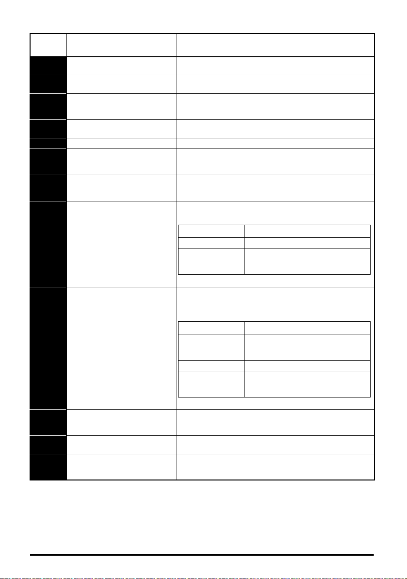
Trip
Sub-trip Reason
1 Reserved
2
The motor did not reach the required
speed during rotating auto-tune or
mechanical load measurement.
Sub-trip Reason
1
Measured inertia has exceeded the
parameter range during a mechanical
load measurement.
2 Reserved
3
The commutation signals changed in
the wrong direction during a rotating
autotune.
code
So.St
St.HF
tH.Fb Internal thermistor has failed Internal thermistor has failed.
tun.S
tunE.1 Autotune 1
Soft start relay failed to close, soft
start monitor failed
Hardware trip has occurred during
last power down
th Motor thermistor over-temperature
th.br Brake resistor over temperature
thS Motor thermistor short circuit
Autotune test stopped before
completion
Condition Description
Soft start relay in the drive failed to close or the soft start
monitoring circuit has failed.
Hardware trip (HF01 –HF19) has occurred and the drive has
been power cycled. Enter 1299 to xx.000 to clear trip
The motor thermistor connected to terminal 14 (digital input 5)
on the control connections has indicated a motor over
temperature.
The th.br trip is initiated if the hardware based braking resistor
thermal monitoring is connected and the resistor overheats.
The motor thermistor connected to terminal 14 (digital input 5)
on the control connections, is short circuit or low impedance
(<50 Ω).
The drive was prevented from completing an autotune test,
because either the drive enable or the drive run signals were
removed.
The drive has tripped during a rotating autotune. The cause of
the trip can be identified from the sub-trip number.
Refer to the Drive User Guide.
RFC-A mode only.
The drive has tripped during a rotating auto-tune or mechanical
load measurement. The cause of the trip can be identified from
the associated sub-trip number.
tunE.3 Autotune 3
Refer to the Drive User Guide.
U.OI User OI ac
U.S User Save error / not completed
US.24
Unidrive M200/201 Control Quick Start Guide 47
Issue Number: 2
User 24 V supply is not present on
the adaptor interface terminals
(1,2)
The U.OI trip is initiated if the output current of the drive exceeds
the trip level set by User Over Current Trip Level. Refer to the
Drive User Guide.
The U.S trip indicates that an error has been detected in the
user save parameters saved in non-volatile memory.
A US.24 trip is initiated if the User Supply Select is set to 1 and
no user 24 V supply is present on the user 24 V input on the AIBackup adaptor. Refer to the Drive User Guide.
Page 48

8.1 Alarm indications
In any mode, an alarm is an indication given on the display by alternating the alarm string with the
drive status string display. If an action is not taken to eliminate any alarm except "tuning and LS" the
drive may eventually trip. Alarms are not displayed when a parameter is being edited.
Table 8-2 Alarm indications
Alarm string Description
Brake resistor overload. Braking Resistor Thermal Accumulator in the drive has
br.res
OV.Ld
d.OV.Ld
tuning The autotune procedure has been initialized and an autotune in progress.
LS
Lo.AC Low voltage mode. See Low AC Alarm in Drive User Guide.
I.AC.Lt Current limit active. See Current Limit Active in Drive User Guide.
reached 75.0 % of the value at which the drive will trip.Refer to the Drive User
Guide
Motor Protection Accumulator in the drive has reached 75.0 % of the value at
which the drive will trip and the load on the drive is >100 %, reduce motor current
(load). Refer to the Drive User Guide
Drive over temperature. Percentage Of Drive Thermal Trip Level in the drive is
greater than 90 %. Refer to the Drive User Guide
Limit switch active. Indicates that a limit switch is active and that is causing the
motor to be stopped.
48 Unidrive M200/201 Control Quick Start Guide
Issue Number: 2
Page 49

9 NV Media Card Operation
1
2
3
Pr = rEAd +00.030
Drive reads all
parameters from
the NV Media Card
Pr = Prog +00.030
Programs all drive
parameters to the
NV Media Card
NOTE
Overwrites any
data already in
data block 1
Pr = Auto +00.030
Drive automatically
writes to the
when a parameter
save is performed
Media Card
Pr = boot +00.030
Drive boots from the
NV Media Card on
power up and
automatically writes
to the
when a parameter
save is performed
Media Card
121
2
1
2
1
2
1
2
Figure 9-1 Installing the AI-Backup adaptor (SD Card)
1. Identify the two plastic fingers on the underside of the AI-Backup adaptor (1) - then insert the two
fingers into the corresponding slots in the spring-loaded sliding cover on the top of the drive.
2. Hold the adaptor firmly and push the spring loaded protective cover towards the back of the drive
to expose the connector block (2) below.
Press the adaptor downwards (3) until the adaptor connector locates into the drive connection below.
Figure 9-2 Basic NV Media Card operation
The whole card may be protected from writing or erasing by setting the read-only flag, refer to the
Drive User Guide for further information. The card should not be removed during data transfer, as the
drive will produce a trip. If this occurs then either the transfer should be reattempted or in the case of
a card to drive transfer, default parameters should be loaded.
Unidrive M200/201 Control Quick Start Guide 49
Issue Number: 2
Page 50

Drive enable
9
10
11
12
Zero frequency
Run forward
13
Run reverse
14
Digital I/O
Analog input 1/
Analog input 2 select
U
BR
+
_
V
W
DC bus/Brake
Motor
L1
L2
L3
3ph
AC power
supply
AC supply
Digital Input 2
24 V user
Digital I/O1
Digital input 3
Digital input 4
Digital input 5
41
42
Drive ok
Relay 1
1
2
0V
Analog I/O
Analog input 1+
7
Analog output 1
4
10 V user
5
Analog input 2
Frequency
reference 1
Frequency
reference 2
Frequency output
Stop
Start
/
Reset
Thermal
protection
device
Braking resistor
Main contactor
power supply
Optional
0478-0282-02
 Loading...