

Page 1

Installation Guide
Universal Variable Speed Drive
for induction and servo motors
0.37kW to 22kW
(0.5HP to 30HP)
Part Number: 0460–0037
Issue Number: 1
Unidrive
LV
Unidrive VTC
Unidrive LFT
model sizes 1 to 3
LV
LV
Page 2

General information
The manufacturer accepts no liability for any
consequences resulting from inappropriate ,
negligent or incorrect installation or adjustment of
the optional operating parameters of the equipment
or from mismatching the variable speed drive
(Drive) with the motor.
The contents of this User Guide are believed to be
correct at the time of printing. In the interests of a
commitment to a policy of continuous development
and improvement, the manufacturer reserves the
right to change the specification of the product or
its performance, or the contents of the User Guide,
without notice.
All rights reserved. No parts of this User Guide may
be reproduced or transmitted in any form or by any
means, electrical or mechanical including
photocopying, recording or by any informationstorage or retrieval system, without permission in
writing from the publisher.
Important...
Drive software version
This product is supplied with the latest version of
user-interface and machine-control software. If this
product is to be used with other Control Techniques
variable speed drives in an existing system, there
may be some differences between their software
and the software in this product. These differences
will cause a difference in functions. This may also
apply to variable speed drives returned from a
Control Techniques Service Centre.
If there is any doubt, contact a Control Techniques
Drive Centre.
Copyright © September 1999 Control Techniques Drives Ltd
Author: RFD
Issue Code: uliu1
Issue Date: September 1999
S/W Version: 03.XX.XX
Page 3

Contents
Chapter
1 Safety Information 1-1
1.1 Warnings, Cautions and Notes 1-1
1.2 Electrical safety – general warning 1-1
1.3 System design 1-1
1.4 Environmental limits 1-1
1.5 Compliance with regulations 1-1
1.6 Safety of personnel 1-1
1.7 Risk analysis 1-2
1.8 Motor 1-2
1.9 Adjusting parameters 1-2
2 Installing the Drive 2-1
2.1 Environmental requirements 2-1
2.2 EMC considerations 2-2
2.3 Planning the installation 2-3
2.4 Calculating the enclosure size 2-14
Appendix
A Motor Connections A-1
A.1 Cable length A-1
A.2 Multiple motors A-1
B UL Listing Information B-1
C Data C-1
C.1 Drive C-1
C.2 Optional RFI filters C-6
2.5 Installing the Drive and RFI filter 2-16
2.6 Power connections 2.27
2.7 Wiring recommendations 2-30
2.8 Variations in the EMC wiring
recommendations 2-36
2.9 Signal connections 2-37
Unidrive LV model sizes 1 to 3 Installation Guide
Issue code: uliu1
i
Page 4
Declaration of Conformity
Control Techniques plc
The Gro
Newtown
Powys
UK
SY16 3BE
UNI1201 UNI1202 UNI1203 UNI1204 UNI1205
UNI2201 UNI2202 UNI2203
UNI3201 UNI3202 UNI3203 UNI3204
The AC variable speed drive products listed above,
including the VTC and LFT variants, have been
designed and manufactured in accordance with the
following European harmonised, national and
international standards:
EN60249 Base materials for printed circuits
IEC326-1 Printed boards: general information for the
IEC326-5 Printed boards: specification for single- and
IEC326-6 Printed boards: specification for multilayer
IEC664-1 Insulation co-ordination for equipment
EN60529 Degrees of protection provided by
UL94 Flammability rating of plastic materials
UL508C Standard for power conversion equipment
EN50081-11Generic emission standard for the
EN50081-2 Generic emission standard for the industrial
EN50082-2 Generic immunity standard for the
EN61800-3 Adjustable speed electrical power drive
1
Conducted emission. See the relevant EMC Data
Sheet.
specification writer
double-sided printed boards with
plated-through holes
printed boards
within low-voltage systems: principles,
requirements and tests
enclosures (IP code)
residential, commercial and light industrial
environment
environment
industrial environment
systems – Part 3: EMC product standard
including specific test methods
These products comply with the Low Voltage
Directive 73/23/EEC, the Electromagnetic
Compatibility (EMC) Directive 89/336/EEC and the
CE Marking Directive 93/68/EEC.
W. Drury
Executive Vice President, Technology
Newtown
Date: 20th September 1999
These electronic Drive products are
intended to be used with appropriate
motors, controllers, electrical
protection components and other
equipment to form complete end
products or systems. Compliance with
safety and EMC regulations depends
upon installing and configuring Drives
correctly, including using the specified
input filters. The Drives must be
installed only by professional
assemblers who are familiar with
requirements for safety and EMC. The
assembler is responsible for ensuring
that the end product or system
complies with all the relevant laws in
the country where it is to be used.
Refer to the Installation Guide. A
Unidrive EMC Data Sheet is also available
giving detailed EMC information.
ii
Unidrive LV model sizes 1 to 3 Installation Guide
Issue code: uliu1
Page 5

1 Safety Information
1.1
Warnings, Cautions
and Notes
A Warning contains information which is essential
for avoiding a safety hazard.
A Caution contains information which is necessary
for avoiding a risk of damage to the product or
other equipment.
A Note contains information which helps to ensure
correct operation of the product.
1.2 Electrical safety –
general warning
1.4 Environmental limits
Instructions in this Installation Guide regarding
transport, storage, installation and use of Drives
must be complied with, including the specified
environmental limits. Drives must not be subjected
to excessive physical force.
1.5 Compliance with
regulations
The installer is responsible for complying with all
relevant regulations, such as national wiring
regulations, accident prevention regulations and
electromagnetic compatibility (EMC) regulations.
Particular attention must be given to the
cross-sectional areas of conductors, the selection of
fuses or other protection, and protective earth
(ground) connections.
This Installation Guide contains instructions for
achieving compliance with specific EMC standards.
The voltages used in the Drive can cause severe
electric shock and/or burns, and could be lethal.
Extreme care is necessary at all times when working
with or adjacent to the Drive.
Specific warnings are given at the relevant places in
this Installation Guide and the accompanying User
Guide.
The installation must comply with all relevant safety
legislation in the country of use.
1.3 System design
The Drive is intended as a component for
professional incorporation into complete equipment
or systems. If installed incorrectly the Drive may
present a safety hazard. The Drive uses high
voltages and currents, carries a high level of stored
electrical energy, and is used to control mechanical
equipment which can cause injury.
Close attention is required to the electrical
installation and the system-design to avoid hazards
either in normal operation or in the event of
equipment malfunction. System-design,
installation, commissioning and maintenance must
be carried out by personnel who have the necessary
training and experience. They must read this safety
information and this Installation Guide carefully.
To ensure mechanical safety, additional safety
devices such as electro-mechanical interlocks may
be required. The Drive must not be used in a safetycritical application without additional high-integrity
protection against hazards arising from a
malfunction.
Unidrive LV model sizes 1 to 3 Installation Guide
Issue code: uliu1
Within the European Union, all machinery in which
this product is used must comply with the following
directives:
98/37/EC: Safety of Machinery
89/336/EEC: Electromagnetic Compatibility.
1.6 Safety of personnel
The STOP function of the Drive does not remove
dangerous voltages from the output of the Drive or
from any external option unit.
The Stop and Start controls or electrical inputs of
the Drive must not be relied upon to ensure safety
of personnel. If a safety hazard could exist from
unexpected starting of the Drive, an interlock that
electrically isolates the Drive from the
must be installed to prevent the motor being
inadvertently started.
Careful consideration must be given to the
functions of the Drive which might result in a
hazard, either through their intended functions
(eg. Auto-start) or through incorrect operation due
to a fault or trip (eg. stop/start, forward/reverse,
maximum speed).
Under certain conditions, the Drive can suddenly
discontinue control of the motor. If the load on the
motor could cause the motor speed to be increased
(eg. hoists and cranes), a separate method of
braking and stopping the motor must be used (eg. a
mechanical brake).
Safety Information 1-1
AC supply
Page 6

Before connecting the AC supply to the Drive, it is
important that you understand the operating
controls and their operation. If in doubt, do not
adjust the Drive. Damage may occur, or lives put at
risk. Carefully follow the instructions in this
Installation Guide.
Standard squirrel-cage induction motors are
designed for single-speed operation. If it is
intended to use the capability of the Drive to run a
motor at speeds above its designed maximum, it is
strongly recommended that the manufacturer is
consulted first.
Before making adjustments to the Drive, ensure all
personnel in the area are warned. Make notes of all
adjustments that are made.
1.7 Risk analysis
In any application where a malfunction of the Drive
could lead to damage, loss or injury, a risk analysis
must be carried out, and where necessary, further
measures taken to reduce the risk. This would
normally be an appropriate form of independent
safety back-up system using simple electromechanical components.
1.8 Motor
Ensure the motor is installed in accordance with the
manufacturer’s recommendations. Ensure the
motor shaft is not exposed.
Low speeds may cause the motor to over-heat
because the cooling fan becomes less effective.
The motor should then be fitted with a protection
thermistor. If necessary, a separate cooling fan
should be used.
If a Drive is to be used to control a number of
motors, special measures need to be taken to ensure
protection of the motors; refer to Motor protection
in Appendix A Motor Information.
1.9 Adjusting parameters
Some parameters have a profound effect on the
operation of the Drive. They must not be altered
without careful consideration of the impact on the
controlled system. Measures must be taken to
prevent unwanted changes due to error or
tampering.
1-2 Safety Information
Unidrive LV model sizes 1 to 3 Installation Guide
Issue code: uliu1
Page 7
2 Installing the Drive
Adhere to the instructions
Warning
Warning
Note
Unless otherwise stated, instructions and
information in this Installation Guide relate
to all versions of the Unidrive.
2.1 Environmental
Warning
The mechanical and electrical
installation instructions must be
adhered to. Any questions or
doubt should be referred to the
supplier of the equipment. It is
the responsibility of the owner
or user to ensure that the
installation of the Drive and any
external option unit, and the way
in which they are operated and
maintained, comply with the
requirements of the Health and
Safety at Work Act in the United
Kingdom or applicable
legislation and regulations and
codes of practice in the country
in which the equipment is used.
Competence of the installer
The Drive must be installed only
by professional assemblers who
are familiar with the
requirements for safety and EMC.
The assembler is responsible for
ensuring that the end-product or
system complies with all the
relevant laws in the country
where it is to be used.
requirements
Installation in an enclosure
The Drive must be protected
against water, condensation and
electrically conductive
contamination. When the gland
plate and appropriate glands are
fitted, the Drive can attain
ingress protection to NEMA 1 and
IP40 (in accordance with
IEC529). UL listing is valid when
the Drive is installed in a type 1
enclosure as defined in UL 50.
Authorized access
Warning
The enclosure should prevent
access by anyone except for
authorized, trained service
personnel.
Fire enclosure
Warning
The Drive case is not classified
as a fire enclosure. When this
protection is required, the
Drive should be installed in a
fire enclosure.
Hazardous areas
Warning
Warning
1. Refer to Appendix C Data for details of the
environmental requirements.
2. If condensation is likely to occur when the Drive
is not in use, an anti-condensation heater must
be installed. This heater must be switched off
when the Drive is in use; automatic switching is
recommended.
3. If the Drive is to be mounted directly above any
heat-generating equipment (such as another
Drive), the maximum temperature of the air
immediately below the Drive should be taken as
the ambient temperature for the Drive.
4. If the Drive is to be mounted beneath other
equipment, such as another Drive, the Drive
should not cause the ambient temperature
requirements of the equipment to be exceeded.
5. When compliance with EMC emission standards
is required, the enclosure must be made of
metal but does not require special EMC
features.
UL-listing requirements are given in Appendix B.
The Drive must not be located
in a classified hazardous area
unless the Drive is installed in
an approved enclosure and the
installation is certified.
Before a Drive is used in the
fully sinusoidal Regeneration
mode, the Drive and the
accompanying motoring
Drive(s) must be modified.
Contact the supplier of the
Drive for details.
Unidrive LV model sizes 1 to 3 Installation Guide
Issue code: uliu1
Installing the Drive 2-1
Page 8
2.2 EMC considerations
Depending on the requirements of the installation,
one of the following levels of electromagnetic
compatibility (EMC) should be adopted:
Routine EMC precautions
These precautions are recommended when
strict compliance with emission standards is not
required. The risk of disturbing adjacent
electronic equipment is minimized by adopting
these precautions.
Compliance with EMC emission
standards
These precautions are recommended when
strict compliance with emission standards is
required. In addition, it is recommended that
these precautions are taken when the Drive is
installed in a residential area, or adjacent to
sensitive electronic equipment such as radio
receivers or similar.
Compliance with EN61800-3
(standard for Power Drive Systems)
Meeting the requirements of this standard
depends on the environment that the Drive is
intended to operate in, as follows:
Operation in the first environment
Observe the guidelines given in Compliance with
EMC emission standards. An RFI filter will always
be required. Some model sizes may require
additional filtering techniques to be applied.
Operation in the second environment
An RFI filter may not be required. Follow the
guidelines given in Routine EMC precautions or
Compliance with EMC emission standards
depending on the requirements of the end user.
The second environment
typically includes an industrial
low-voltage power supply
Caution
Instructions are given later in this chapter for these
levels of EMC. Refer to Appendix C Data for further
information on compliance with EMC standards and
definitions of environments.
Detailed instructions and EMC information are given
in the Unidrive LV EMC Data Sheet which is available
from the Drive Centres and distributors listed at the
end of this Installation Guide.
Compliance data is given in Appendix C Data.
network which does not supply
buildings used for domestic
purposes. Operating the Drive
in this environment without an
RFI filter may cause
interference to nearby
electronic equipment whose
sensitivity has not been
appreciated. The user must
take remedial measures if this
situation arises. If the
consequences of unexpected
disturbances are severe, it is
recommended that the
emission limits of EN50081-2 be
adhered to.
Note
The installer of the Drive is responsible for
ensuring compliance with the EMC
regulations that apply where the Drive is to
be used.
The Drive will comply with the standards
for emission, such as EN50081–2, only when
the instructions given in Planning the
installation and Wiring recommendations later
in this chapter are followed closely.
2-2 Installing the Drive
Unidrive LV model sizes 1 to 3 Installation Guide
Issue code: uliu1
Page 9

2.3 Planning the installation
Model
UNI 1201
UNI 1202
UNI 1203
UNI 1204
UNI 1205
UNI 2201
UNI 2202
UNI 2203
UNI 3201
UNI 3202
UNI 3203
UNI 3204
Table 2–1 Fuse ratings for all versions of
the Unidrive LV
Instructions in numbered steps
The instructions in this section are contained in
numbered steps. In some of these steps you will
need to make a note of a value for future reference
and, to help with identification, the number of the
step.
AC supply protection
The
AC supply to the Drive must
be fitted with suitable
Warning
protection against overload
and short-circuits. Table 2–1
shows recommended fuse
ratings. Failure to observe this
recommendation will cause a
risk of fire.
TEP 1 Include a fuse of the specified rating in
S
each phase of the
AC supply. The use of the
following types of fuse is recommended:
• Europe: Type gG HRC industrial fuses to
IEC 269 (BS88)
• USA: RK1 600V
AC
An MCB or MCCB having the correct thermal
and magnetic trip ratings may be used in place
of fuses, on condition the fault-current clearing
capacity is sufficient for the installation.
Power cables
Wiring must be in accordance
with local regulations and
Warning
Cable type and size
codes of practice. The table
below shows typical cable sizes
for power input and output
wiring. In the event of a
conflict, local regulations
prevail.
Fuse rating
6 A
10 A
10 A
16 A
16 A
16 A
20 A
35 A
40 A
60 A
70 A
80 A
Note
UL listing is dependent on the use of the
correct type of UL-listed fuse, and applies
when the symmetrical short-circuit current
does not exceed 5kA. Refer to Appendix B
UL Listing Information.
STEP 2 For the following power connections...
•
AC supply to RFI filter (when used)
•
AC supply (or RFI filter) to Drive
• Drive to motor
• Drive to braking resistor
... use 105°C (221°F) pvc-insulated cable of
suitable voltage rating and having copper
conductors, as shown in Table 2–2.
Unidrive LV model sizes 1 to 3 Installation Guide
Issue code: uliu1
Installing the Drive 2-3
Page 10
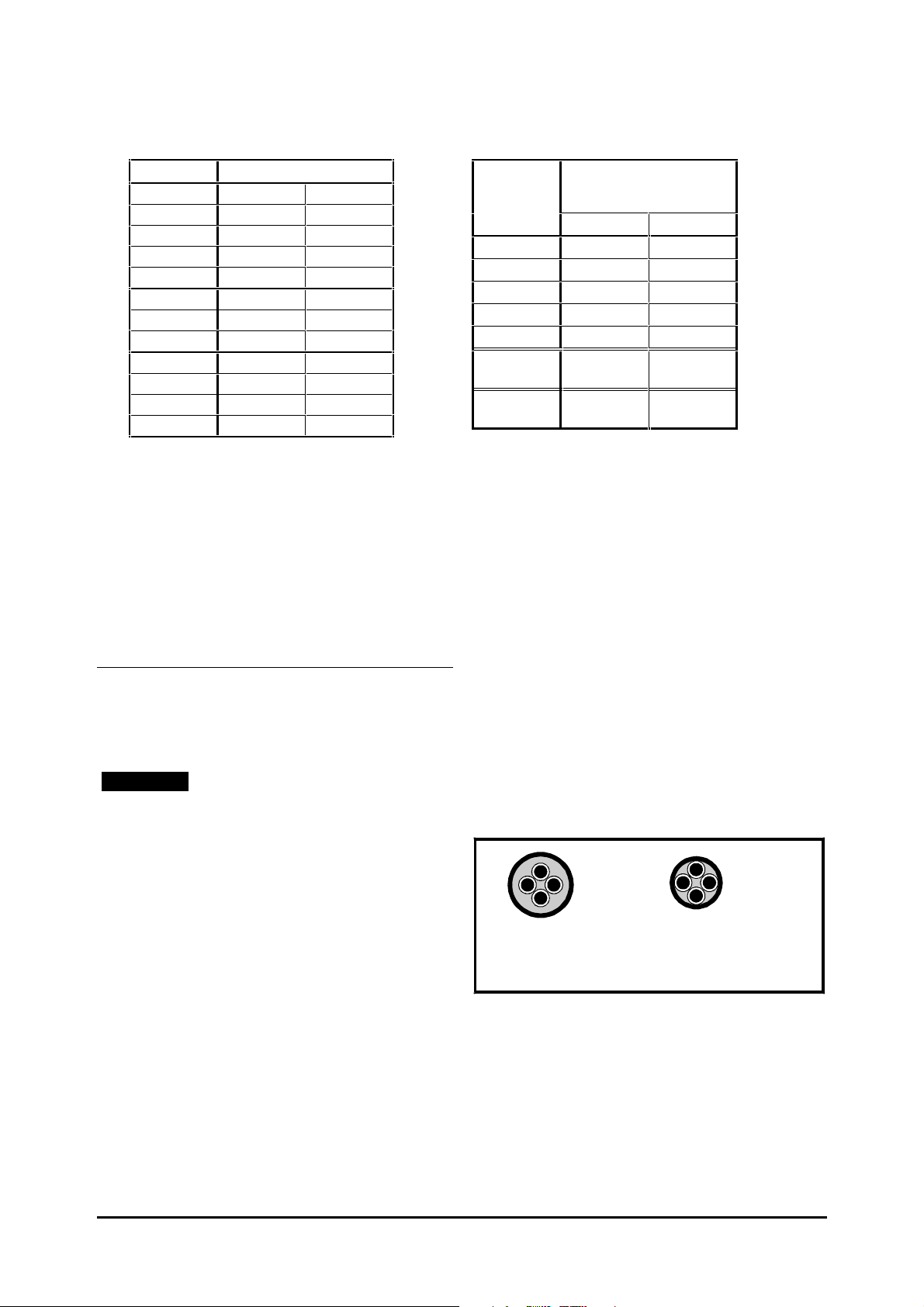
Table 2–2 Cable sizes
ft
210
330
430
660
990
990
660
Table 2–3 Maximum cable lengths
Model Cable size
UNI 1201 1.5 mm
UNI 1202 2.5 mm
UNI 1203 2.5 mm
UNI 1204 2.5 mm
UNI 1205 2.5 mm
UNI 2201 2.5 mm
UNI 2202 4 mm
UNI 2203 4 mm
UNI 3201 6 mm
UNI 3202 10 mm
UNI 3203 16 mm
UNI 3204 25 mm
2
16 AWG
2
14 AWG
2
14 AWG
2
14 AWG
2
14 AWG
2
2
2
2
2
2
2
14 AWG
10 AWG
10 AWG
8 AWG
6 AWG
4 AWG
4 AWG
When EMC emission requirements are to be
met, shielded cable or steel wire armoured
cable may be required for the following:
AC supply to enclosure
•
• Drive to motor
• Drive to braking resistor when part of the
cable is outside the enclosure
For further details, see Wiring guidelines later in this
chapter.
Motor cable
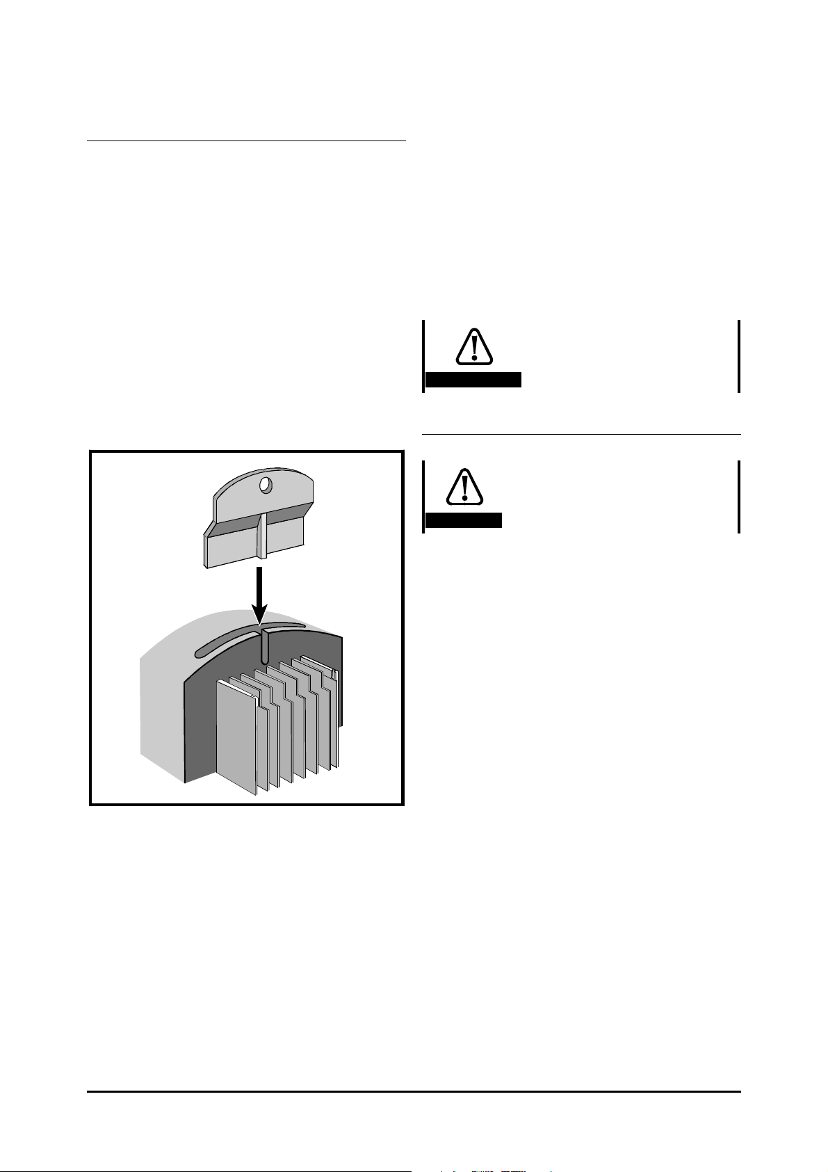
STEP 3 Since capacitance in the motor cable
causes loading on the output of the Drive,
ensure the cable length does not exceed the
values given in Table 2–3.
Note
Maximum length of the encoder cable
Model Maximum cable length *
UNI 1201 65
UNI 1202 100
UNI 1203 130
UNI 1204 200
UNI 1205 300
UNI 2201 ~
UNI 2203
UNI 3201 ~
UNI 3204
* Cable lengths in excess of the specified values may be
used only when special techniques are adopted; refer to
the supplier of the Drive.
(
PWM switching
frequency at 3kHz)
m
300
200
The maximum cable length is reduced from that
shown in the table under the following
conditions:
PWM switching frequency exceeding
•
3kHz in model size 3 The maximum
cable length is reduced in proportion to the
increase in
9kHz, the maximum length is
PWM switching frequency, eg. at
1
/3 of that
shown.
• High-capacitance cables Most cables
have an insulating jacket between the cores
and the armour or shield; these cables have a
low capacitance and are recommended.
Cables that do not have an insulating jacket
tend to have high capacitance; if a cable of
this type is used, the maximum cable length
is half that quoted in the table. (Figure 2–1
shows how to identify the two types.)
When a Unidrive LV or Unidrive LFT LV is to
be used in a closed-loop system and with
long motor cables, the corresponding
length of the encoder cable may cause an
excessive supply-voltage drop between the
Drive and encoder. In this case, do not use
the Drive to supply the encoder; install a
separate
DC supply close to the encoder.
2-4 Installing the Drive
Normal capacitance
Shield or armour
separated from the cores
High capacitance
Shield or armour close
to the cores
Figure 2–1 Cable construction influencing
the capacitance
Multiple motors
Special requirements apply when the Drive is to
control more than one motor. Refer to
Appendix A Motor Connections.
Unidrive LV model sizes 1 to 3 Installation Guide
Issue code: uliu1
Page 11
Isolator switch in the motor cable
An isolator switch may be connected in the
motor cable for safety purposes. Refer to the
following Warning and Note.
The isolator switch must not be
operated when the Drive is
AC-rated switch
Warning
enabled. (If an
is used and the Drive is
producing a low output
frequency when the switch is
opened, severe arcing can occur
which will prevent the switch
from breaking the circuit.)
A suitable interlock
arrangement can be used, such
as an isolator switch fitted
with additional contacts that
open before the main contacts.
These additional contacts
should be used to disable the
Drive.
Note
If the isolator switch is closed when the
Drive is enabled, the Drive may trip.
When EMC compliance is required, refer to Variations
in the EMC wiring recommendations later in this
chapter.
The Drive has two forms of thermal protection for
the power output stage (IGBT bridge), as follows:
1. A thermistor mounted on the heatsink monitors
the heatsink temperature. If this exceeds 95°C
(203°F), the thermistor will cause the Drive to
trip. The display will indicate Oh2.
2. Intelligent thermal modelling estimates (by
calculation) the junction temperature of the
IGBTs. There are two temperature thresholds
which cause the following to occur:
• If the first threshold is reached, the
PWM
switching frequency is halved in order to
reduce dissipation in the IGBTs. (When the
frequency is halved, the value of parameter
PWM switching frequency remains at the
0.41
value set by the user; if the frequency is 3kHz
or 4.5kHz, no halving occurs). Then at one
second intervals, the Drive will attempt to
restore the original
PWM switching
frequency. This will be successful if the
estimated temperature has reduced
sufficiently.
• If the estimated temperature has continued
to rise and reaches a second threshold, the
Drive will trip. The display will indicate Oh1.
TEP 4 Note that the Drive can deliver an
S
overload current, as shown in Table 2–4.
Table 2–4 Overload current
Output current,
PWM switching frequency,
Ambient temperature
Thermal protection
Note
The Drive can supply the rated current up
to an ambient temperature of 40
(depending on the
PWM switching frequency
used).
The Drive can be operated in an ambient
temperature up to 50
o
C (122oF) at de-rated
output current. In this case, ensure the
value of parameter 0.46 Motor rated current
does not exceed the value given in
Table 2-5.
o
C (104°°F)
Unidrive LV
Open-loop
Up to 150% of the rated current for 60 seconds
Closed-loop Vector
Up to 175% of the rated current for 60 seconds
Closed-loop Servo
Up to 175% of the rated current for 4 seconds
Unidrive VTC LV
For a variable-torque load
Up to 120% of the rated current for 60 seconds
Unidrive LFT LV operating on
standard S4/S5 duty cycle
Open-loop
Up to 150% of the rated current
Closed-loop Vector
Up to 175% of the rated current
Closed-loop Servo
Up to 175% of the rated current
Unidrive LV model sizes 1 to 3 Installation Guide
Issue code: uliu1
Installing the Drive 2-5
Page 12
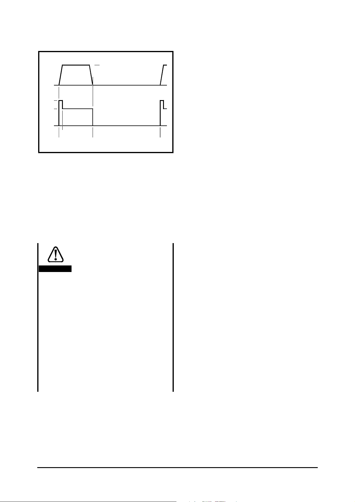
150%
100%
Frequency / speed
0
Current
0
2
0
50Hz
1500
RPM
20 60
Figure 2–2 Standard S4/S5 duty cycle
(Unidrive LFT LV)
Unidrive LV and Unidrive VTC LV Refer
to Table 2–5 to find the maximum continuous
output current that can be obtained for the
required ambient temperature and
PWM switching frequency. The maximum
ambient temperature can be 40°C or 50°C
(104°F or 122°F). Note that the nominal power
rating of the Drive may not be achieved above
40°C.
Unidrive LFT LV Refer to Table 2–6 to find
the maximum continuous output current that
can be obtained for the ambient temperature
for a standard S4/S5 duty-cycle or for
continuous operation. Refer to a Drive Centre
or distributor for information on other duty
ratios.
Make a note of this step number and the
following:
• Unidrive LV and Unidrive VTC LV
Chosen maximum ambient temperature.
• Unidrive LV and Unidrive VTC LV
Chosen
PWM switching frequency for
each Drive.
• All Unidrive LV versions From Table 2–
7, the maximum power dissipation (heat)
figure (PP
) at the chosen PWM switching
DISSDISS
frequency for each Drive (this figure is the
total power dissipation at the maximum
continuous output current available at the
chosen
PWM switching frequency, and
includes power dissipated in option modules
when fitted). Power dissipation in the
Unidrive LFT is the same as that for the
standard Unidrive when operating at 9kHz
PWM switching frequency.
Caution
Operation in a maximum
ambient temperature of 50°°C
(122°°F)
Unless the precaution described
here is taken, the Drive will
limit the maximum continuous
output current only to the
value for 40°°C, and not to the
value stated in Table 2–5 for
50°°C.
Make a note of the value for
50°°C; you will need to refer to
it when you reach Configuring
the Drive for the motor in
Chapter 2 of the User Guide.
At that point, ensure that the
value to be entered in
parameter 0.46 Motor – rated
current does not exceed the
noted value.
• Unidrive LV and Unidrive VTC LV If
the maximum ambient temperature will be
50°C (122°F), note the value of the
maximum permissible output current
obtained from Table 2–5. This will be the
maximum value that parameter 0.46 Motor
– rated current should be set at.
2-6 Installing the Drive
Unidrive LV model sizes 1 to 3 Installation Guide
Issue code: uliu1
Page 13

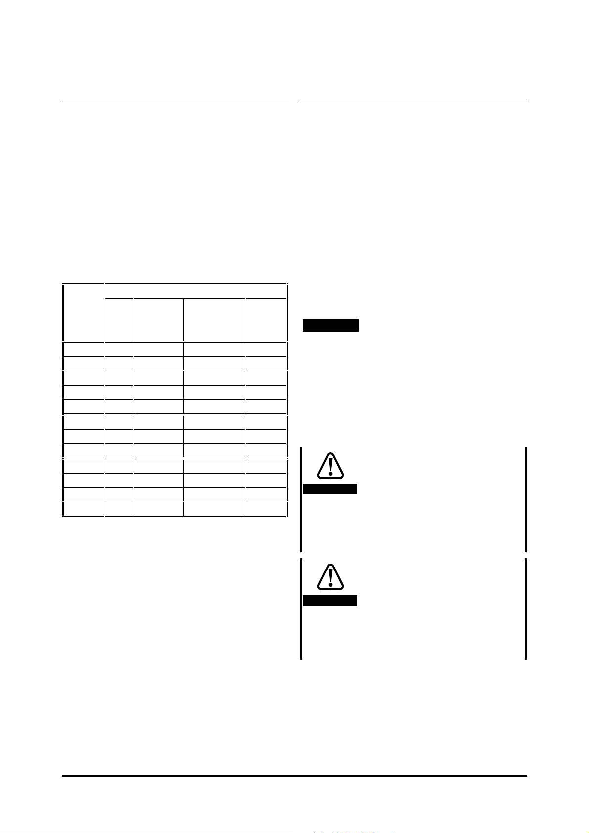
Table 2–5 Maximum permissible continuous output current for Unidrive LV and Unidrive VTC LV
40°°C (104°F)
ambient
Model kW HP 3kHz 4.5kHz 6kHz 9kHz 12kHz
UNI 1201 0.37 kW 0.5 2.1 A 2.1 A 2.1 A 2.1 A 2.1 A
UNI 1202 0.55 kW 0.75 2.8 A 2.8 A 2.8 A 2.8 A 2.8 A
UNI 1203 0.75 kW 1.0 3.8 A 3.8 A 3.8 A 3.8 A 3.8 A
UNI 1204 1.1 kW 1.5 5.6 A 5.6 A 5.6 A 5.6 A 4.5 A
UNI 1205 2.2 kW 3.0 9.5 A 9.5 A 8.5 A 7.0 A 5.5 A
UNI 2201 3.0 kW 4.0 12.0 A 12.0 A 12.0 A 12.0 A 11.7 A
UNI 2202 4.0 kW 5.0 16.0 A 16.0 A 16.0 A 14.2 A 11.7 A
UNI 2203 5.5 kW 10.0 25.0 A 21.7 A 18.2 A 14.2 A 11.7 A
UNI 3201 7.5 kW 15.0 34.0 A 34.0 A 34.0 A 28.0 A 23.0 A
UNI 3202 11 kW 20.0 46.0 A 46.0 A 40.0 A 32.0 A 26.6 A
UNI 3203 15 kW 25.0 60.0 A 47.0 A 40.0 A 32.0 A 26.7 A
UNI 3204 22 kW 30.0 74.0 A 56.0 A 46.0 A 35.0 A 28.0 A
50°°C (122°F)
ambient
Model kW HP 3kHz 4.5kHz 6kHz 9kHz 12kHz
UNI 1201 0.37 kW 0.5 2.1 A 2.1 A 2.1 A 2.1 A 2.1 A
UNI 1202 0.55 kW 0.75 2.8 A 2.8 A 2.8 A 2.8 A 2.8 A
UNI 1203 0.75 kW 1.0 3.8 A 3.8 A 3.8 A 3.8 A 3.3 A
UNI 1204 1.1 kW 1.5 5.6 A 5.6 A 5.1 A 4.0 A 3.3 A
UNI 1205 2.2 kW 3.0 6.9 A 5.9 A 5.1 A 4.0 A 3.3 A
UNI 2201 3.0 kW 4.0 12.0 A 12.0 A 12.0 A 11.6 A 9.7 A
UNI 2202 4.0 kW 5.0 16.0 A 16.0 A 14.7 A 11.6 A 9.7 A
UNI 2203 5.5 kW 10.0 20.0 A 17.3 A 14.7 A 11.6 A 9.7 A
UNI 3201 7.5 kW 15.0 34.0 A 34.0 A 28.0 A 21.0 A 17.9 A
UNI 3202 11 kW 20.0 44.0 A 36.0 A 31.0 A 24.0 A 20.6 A
UNI 3203 15 kW 25.0 44.0 A 36.0 A 31.0 A 24.0 A 20.9 A
UNI 3204 22 kW 30.0 50.0 A 41.0 A 34.0 A 26.0 A 23.0 A
Nominal
rating
Nominal
rating
Maximum permissible
continuous output current
Maximum permissible
continuous output current
Unidrive LV model sizes 1 to 3 Installation Guide
Issue code: uliu1
Installing the Drive 2-7
Page 14

Table 2–6 Maximum permissible output current for Unidrive LFT LV
Continuous
operation at 40°C
2.1 A
2.8 A
3.8 A
4.0 A
4.3 A
12.0 A
14.2 A
14.2 A
28.0 A
32.0 A
33.0 A
35.0 A
Model
UNI 1201
UNI 1202
UNI 1203
UNI 1204
UNI 1205
UNI 2201
UNI 2202
UNI 2203
UNI 3201
UNI 3202
UNI 3203
UNI 3204
(at 9kHz
PWM switching frequency)
Model Nominal
rating
kW HP Standard duty cycle
at 40°°C
UNI 1201 LFT 0.37 kW 0.5 2.1 A
UNI 1202 LFT 0.55 kW 0.75 2.8 A
UNI 1203 LFT 0.75 kW 1.0 3.8 A
UNI 1204 LFT 1.1 kW 1.5 5.6 A
UNI 1205 LFT 2.2 kW 3.0 9.5 A
UNI 2201 LFT 3.0 kW 4.0 12.0 A
UNI 2202 LFT 4.0 kW 5.0 16.0 A
UNI 2203 LFT 5.5 kW 10.0 25.0 A
UNI 3201 LFT 7.5 kW 15.0 34.0 A
UNI 3202 LFT 11 kW 20.0 46.0 A
UNI 3203 LFT 15 kW 25.0 60.0 A
UNI 3204 LFT 22 kW 30.0 74.0 A
Maximum permissible output current
Continuous
operation at 50°°C
2.1 A
2.8 A
3.3 A
3.3 A
3.3 A
11.0 A
11.0 A
11.0 A
21.0 A
24.0 A
24.0 A
26.0 A
Table 2–7 Maximum total power dissipation (Unidrive LV, Unidrive VTC LV and Unidrive LFT LV)
Nominal
rating
kW HP 3kHz 4.5kHz 6kHz 9kHz 12kHz
0.37kW 0.5 80 W 80 W 90 W 90 W 90 W
0.55kW 0.75 90 W 90 W 100 W 100 W 110 W
0.75kW 1.0 100 W 110 W 110 W 120 W 130 W
1.1kW 1.5 130 W 130 W 140 W 150 W 150 W
2.2kW 3.0 180 W 190 W 190 W 190 W 170 W
3.0kW 4.0 210 W 230 W 250 W 280 W 310 W
4.0kW 5.0 270 W 290 W 310 W 320 W 310 W
5.5kW 10.0 400 W 380 W 360 W 330 W 310 W
7.5kW 15.0 570 W 620 W 670 W 660 W 630 W
11kW 20.0 730 W 800 W 770 W 730 W 700 W
15kW 25.0 950 W 830 W 790 W 740 W 710 W
22kW 30.0 1090 W 990 W 920 W 850 W 800 W
Maximum total power dissipation
The default PWM switching frequency is a follows...
2-8 Installing the Drive
Unidrive LV and Unidrive VTC LV: 3kHz
Unidrive LFT LV: 9kHz
Unidrive LV model sizes 1 to 3 Installation Guide
Issue code: uliu1
Page 15
Using an RFI filter
Using a braking resistor
STEP 5 For compliance with the emission
standards such as EN 50081-1 or EN 50081-2, use
the recommended RFI filter as shown in
Table 2–8. Use one RFI filter for each Drive.
(Standards that are met are specified in
Appendix C Data)
Make a note of this step number and the
following for each filter to be used:
• Size code or part number
• Maximum power dissipation figure
• IP rating
Table 2–8 RFI filter data
Model RFI filter
IP
rating
UNI 1201
UNI 1202
UNI 1203
UNI 1204
UNI 1205
UNI 2201
UNI 2202
UNI 2203
UNI 3201
UNI 3202
UNI 3203
UNI 3204
Size Part
number
A
4200–0010 25 IP20
A
4200–0010 25 IP20
A
4200–0010 25 IP20
A
4200–0010 25 IP20
A
4200–0010 25 IP20
B
4200–0027 40 IP20
B
4200–0027 40 IP20
B
4200–0027 40 IP20
C
4200–1051 60 IP00
C
4200–1051 60 IP00
D
4200–1071 100 IP00
D
4200–1071 100 IP00
Maximum
power
dissipation
(W)
Model size 1
When the motor cable is to exceed 50m (165 feet),
use RFI filter size B (4200–0027).
Braking occurs when the Drive is decelerating the
motor, or is preventing the motor from gaining
speed due to mechanical influences. During braking,
energy is returned to the Drive by the motor.
When the motor is being braked by the Drive, the
maximum regenerated power that the Drive can
absorb is equal to the power dissipation (losses) of
the Drive.
When the regenerated power is likely to exceed
these losses, a braking resistor must be connected.
By default, the Drive brakes the motor under
PI control which extends the deceleration time as
necessary in order to keep the
DC bus at a constant
voltage. The method of braking can be changed; if
required, refer to Appendix D Menu 0 Parameters in
the User Guide.
Note
When a braking resistor is used, the Drive
should be operated in FASt ramp mode. If
this is not done, instability may arise. See
Braking resistor in Chapter 2 of the User
Guide.
Housing the resistor, and routing the
connecting cable
High temperatures
Braking resistors can reach
Warning
high temperatures. Locate
braking resistors so that
damage cannot result.
Use cable having insulation
capable of withstanding high
temperatures.
Overload protection
Unidrive LV model sizes 1 to 3 Installation Guide
Issue code: uliu1
Warning
It is essential that an overload
protection device is
incorporated in the braking
resistor circuit; this is
described in Protection circuit
for an optional braking resistor in
TEP 8.
S
Installing the Drive 2-9
Page 16
STEP 6 When a braking resistor is to be mounted
outside the enclosure, ensure that it is mounted
in a ventilated metal housing that will perform
the following functions:
• Prevent inadvertent contact with the
resistor
• Allow adequate ventilation for the resistor
When compliance with EMC emission standards
is required, external connection requires the
cable to be armoured or shielded, since it is not
fully contained in a metal enclosure.
Internal connection does not require the cable
to be armoured or shielded.
Minimum resistances and power ratings
Table 2–9 Minimum resistance values and
peak power rating for the
braking resistor at 40°°C (104°°F)
Model Minimum
resistance
UNI 1201 ~ UNI 1205 20Ω 15kW
UNI 2201 20Ω 15kW
UNI 2202, UNI 2203 15Ω 20kW
UNI 3201 ~ UNI 3204 5Ω 60kW
The minimum resistance allows the braking resistor
to dissipate up to approximately 300% of the power
rating of the Drive for up to 60 seconds.
For high-inertia loads or under continuous braking,
the continuous power dissipated in the braking
resistor may be as high as the power rating of the
Drive. The total energy dissipated in the braking
resistor is dependent on the amount of energy to be
extracted from the load.
The instantaneous power rating refers to the
short-term maximum power dissipated during the on
intervals of the pulse width modulated braking
control cycle. The braking resistor must be able to
withstand this dissipation for short intervals
(milliseconds). Higher resistance values require
proportionately lower instantaneous power ratings.
In most applications, braking occurs only
occasionally. This allows the continuous power
rating of the braking resistor to be much lower than
the power rating of the Drive. It is essential,
though, that the instantaneous power rating and
energy rating of the braking resistor are sufficient
for the most extreme braking duty that is likely to
be encountered.
Instantaneous
power rating
Optimization of the braking resistor requires a
careful consideration of the braking duty. This is
described more fully in Optimizing an optional braking
resistor in the Unidrive Advanced User Guide.
TEP 7 Select a value of resistance for the braking
S
resistor that is not less than the specified
minimum resistance. Larger resistance values
may give a cost saving, as well as a safety
benefit in the event of a fault in the braking
system. Braking capability will then be
reduced, which may cause the Drive to trip
during braking. If this occurs, refer to
Deceleration rate in Chapter 2 of the User Guide.
TEP 8 Estimate the average power that will be
S
dissipated in the resistor. A method of
estimating this power is described in Optimizing
an optional braking resistor in the Unidrive
Advanced User Guide. Make a note of this step
number and the average power to be dissipated
in the resistor.
Thermal protection circuit for the
braking resistor
The thermal protection circuit must disconnect the
AC supply from the Drive if the resistor becomes
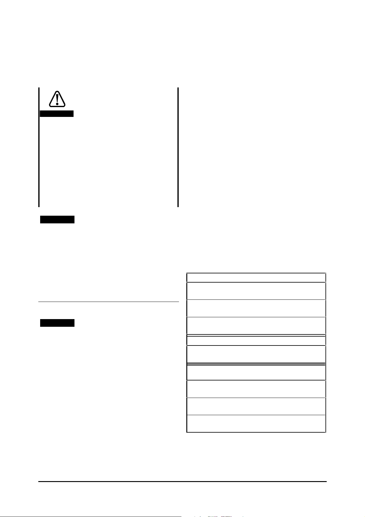
overloaded. Figure 2–3 shows a typical circuit
arrangement.
Optional
RFI filter
Stop
Start /
Reset
Thermal
protection
device
Braking resistor
Figure 2–3 Typical protection circuit for a
braking resistor
Drive
2-10 Installing the Drive
Unidrive LV model sizes 1 to 3 Installation Guide
Issue code: uliu1
Page 17

Enclosure layout
STEP 9 Use one of the following enclosure
layouts, depending on the requirements of the
installation:
Routine EMC precautions Refer to
Figure 2–4 which shows the recommended
layout for two Drives, and the signal and power
cables.
Compliance with EMC emission
standards Refer to Figure 2–5 which shows
the recommended layout for two Drives, two
RFI filters, and the signal and power cables.
TEP 10 Decide whether the enclosure is to be
S
sealed or ventilated, as follows:
A sealed enclosure can give a high ingress-
protection rating, but with reduced heat
removal capabilities. If possible, locate heatgenerating equipment (other than braking
resistors) in the lower part of the enclosure to
encourage internal convection. If necessary, a
taller enclosure, and/or air-circulation fans
inside the enclosure, can be used. For
calculating the minimum size of sealed
enclosure that will adequately cool the Drive(s),
refer later in this chapter to Calculating the size
of a sealed enclosure.
If a high ingress-protection rating is not
required, a ventilated enclosure can be used
with a fan to supply forced air cooling; this can
give a lower ambient temperature than a sealed
enclosure. For calculating the minimum
required volume of cooling air, refer later in this
chapter to Calculating the air-flow in a ventilated
enclosure.
TEP 11 For compliance with EMC emission
S
standards, ensure the enclosure is fitted with an
unpainted metal back-plate for mounting the
Drive and RFI filter. For example, a zinc plated
steel back-plate is suitable (see Figure 2–5).
TEP 12 Ensure the Drive is installed vertically for
S
best flow of cooling air through the Drive and
heatsink.
TEP 13 Ensure the clearances around the Drive are
S
as follows:
Above and below: ≥100mm (4 in)
1
Both sides: ≥5mm (
/4 in)
Note
When surface mounting a model size 3,
allow a clearance of 150mm (6in) above the
Drive; this is required for dismounting. A
minimum clearance of 100mm (4in) is
required for ventilation.
For overall dimensions and weights of the Drive
and RFI filter, see Appendix C Data.
TEP 14 When compliance with EMC emission
S
standards is required, the RFI filter must be
installed at the specified position for each Drive
(see Figure 2–5).
TEP 15 When a braking resistor is to be used, it
S
can be installed outside or inside the enclosure.
When installed inside, it must be mounted in
the upper part of the enclosure to prevent it
heating the other equipment by convection.
Unidrive LV model sizes 1 to 3 Installation Guide
Issue code: uliu1
Installing the Drive 2-11
Page 18

Optional braking resistors as required for the Drives
External: Mount on top surface of enclosure.
Internal: Mount in top part of enclosure.
Drives
Ensure minimum
clearances are
respected.
System controller
Locate as required.
Signal cables
Plan for all signal
cables to be routed at
least 300mm (12in)
distant from any
power cable.
Power cables
AC supply isolator,
contactor, and
fuses or MCBs
Locate as required.
≥100mm
(4in)
≥5mm
(¼in)
Overload protection
device
≥100mm
(4in)
Location
of optional
terminal
block
Alternative
location of
fuses or
MCBs
Locate as
required.
≥5mm
(¼in)
Back-plate
Enclosure
Figure 2–4 Recommended layout for routine EMC precautions (wiring recommendations
are given in Figure 2–21)
2-12 Installing the Drive
Unidrive LV model sizes 1 to 3 Installation Guide
Issue code: uliu1
Page 19

Optional braking resistors as required for the Drives
External: Mount on top surface of enclosure.
Internal: Mount in top part of enclosure.
Overload protection
device
Alternative location
of fuses or MCBs
Drives and
RFI filters
Ensure minimum
clearances are
respected.
Locate as required.
≥5mm
(¼in)
≥100mm
(4in)
≥5mm
(¼in)
System controller
Locate as required.
Signal cables
Plan for all signal
cables to be routed at
least 300mm (12in)
distant from any power
cable.
RFI filters
nstall a separate RFI
I
filter for each Drive.
Power cables
AC supply isolator,
contactor, and
fuses or MCBs
Locate as required.
Alternative location of
fuses or MCBs
Locate as required.
≥5mm
(¼in)
150mm
(6in)
Location
of optional
terminal
block
Enclosure
Figure 2–5 Recommended layout for compliance with EMC emission standards
(wiring recommendations are given in Figures 2–22 and 2–23)
Back-plate
Unidrive LV model sizes 1 to 3 Installation Guide
Issue code: uliu1
Installing the Drive 2-13
Page 20

2.4 Calculating the
enclosure size
STEP 1 Add the dissipation figures from step 4 of
Planning the installation for each Drive that is to
be installed in the enclosure. Make a note of
this step number and the total value.
TEP 2 If an RFI filter is to be used with each
S
Drive, add the dissipation figures from step 5 of
Planning the installation for each RFI filter that is
to be installed in the enclosure. Make a note of
this step number and the total value.
TEP 3 If the braking resistor is to be mounted
S
inside the enclosure, add the average power
figures from step 8 of Planning the installation for
each braking resistor that is to be installed in
the enclosure. Make a note of this step number
and the total value.
TEP 4 Make a note of this step number and the
S
total heat dissipation (in Watts) of any other
equipment to be installed in the enclosure.
TEP 5 Add the heat dissipation figures obtained
S
(as appropriate) from steps 1, 2, 3 and 4 above.
This gives a figure in Watts for the total heat
that will be dissipated inside the enclosure.
Make a note of this figure and the step number.
Calculating the size of a
sealed enclosure
P Power in Watts dissipated by all heat
sources in the enclosure
k Heat transmission coefficient of the
enclosure material in W/m
2
/°C
Example
To calculate the size of an enclosure for the
following:
• Two UNI 1205 models
• Each Drive to operate at 4.5kHz
switching frequency
• RFI filter for each Drive
• Braking resistors are to be mounted outside
the enclosure
• Maximum ambient temperature inside the
enclosure: 40°C
• Maximum ambient temperature outside the
enclosure: 30°C
Dissipation of each Drive: 190W (from step 4 in
Planning the installation)
Dissipation of each RFI filter: 25W (max) (from
step 5 in Planning the installation)
Total dissipation: 2 x (190 + 25) = 430W
The enclosure is to be made from painted 2mm
3
/32in) sheet steel having a heat transmission
(
coefficient of 5.5W/m
2
/°C. Only the top, front, and
two sides of the enclosure are to be free to
dissipate heat.
PWM
The enclosure transfers internally generated heat
into the surrounding air by natural convection (or
external forced air flow); the greater the surface
area of the enclosure walls, the better is the
dissipation capability. Only the surfaces of the
enclosure that are unobstructed (not in contact
with a wall or floor) can dissipate heat.
Calculate the minimum required unobstructed
surface area A
A=
e
for the enclosure from:
e
P
k(T - T )
int ext
Where:
A
e
Unobstructed surface area in m
2
(1m2 = 10.8 ft2)
T
ext
Maximum expected ambient
temperature in °C outside the enclosure
T
int
Maximum permissible ambient
temperature in °C inside the enclosure
Figure 2–6 Enclosure having front, sides and
top panels free to dissipate heat
2-14 Installing the Drive
Unidrive LV model sizes 1 to 3 Installation Guide
Issue code: uliu1
Page 21

Insert the following values:
T
40°C
int
T
30°C
ext
k 5.5
P 430W
The minimum required heat conducting area is then:
A=
e
430
5.5(40 - 30)
22
= 7.8m (85ft )
(1m = 3.3 ft)
Estimate two of the enclosure dimensions — the
height (H) and depth (D), for instance. Calculate
the width (W) from:
A - 2HD
e
W=
H+D
Inserting H = 2m and D = 0.6m, obtain the minimum
width:
××××
7.8 - (2 )
W=
20621.
2+0.6
m (6ft 10in)
==
.
If the enclosure is too large for the space available,
it can be made smaller only by attending to one or
all of the following:
• Using a lower
PWM switching frequency to
reduce the dissipation in the Drives (return
to step 4 in Planning the installation)
• Reducing the ambient temperature outside
the enclosure, and/or applying forced-air
cooling to the outside of the enclosure
• Reducing the number of Drives in
the enclosure
• Removing other heat-generating equipment
Calculating the air-flow in a
ventilated enclosure
Where:
V Air-flow in m
T
ext
Maximum ambient temperature in °C
3
per hour
outside the enclosure
T
int
Maximum ambient temperature in °C
inside the enclosure
P Power in Watts dissipated by all heat
sources in the enclosure
p
k Ratio of
0
P
I
Where:
P
is the air pressure at sea level
0
P
is the air pressure at the
I
installation
Typically use a factor of 1.2 to 1.3, to
allow also for pressure-drops in dirty
air-filters.
Example
To calculate the size of an enclosure for the
following:
• Three UNI 3201 models
• Each Drive to operate at 6kHz
frequency
• RFI filter for each Drive
• Braking resistors are to be mounted outside
the enclosure
• Maximum ambient temperature inside the
enclosure: 40°C
• Maximum ambient temperature outside the
enclosure: 30°C
Dissipation of each Drive: 670W (from step 4 in
Planning the installation)
Dissipation of each RFI filter: 60W (max) (from
step 5 in Planning the installation)
Total dissipation: 3 x (670 + 60) = 2190W
PWM switching
The dimensions of the enclosure are required only
for accommodating the equipment. The equipment
is cooled by the forced air flow.
Calculate the minimum required volume of
ventilating air from:
3kP
V=
T-T
ext
int
Unidrive LV model sizes 1 to 3 Installation Guide
Issue code: uliu1
Insert the following values:
40°C
T
int
T
30°C
ext
k 1.3
P 2190W
Then:
32190
××××
V=
.
40-30
==13854
(1m3/hr = 0.59ft3/min)
Installing the Drive 2-15
33
m / hr (504 ft
/min)
Page 22

2.5 Installing the Drive
and RFI filter
Lifting the Drive
Warning
The weight of model size 3 is
22kg (49 lbs). Use appropriate
safeguards when lifting this
model.
Removing the terminal covers
The Drive is fitted with one or two terminal covers
depending on the model size. When model sizes 1
and 3 are through-panel mounted, the terminal
cover(s) must first be removed in order for access
to be gained to the lower mounting holes.
Figure 2–8 View from the underside showing
how a terminal cover is removed
from the Drive
Remove terminal covers, as follows:
1. Working on either side of the terminal cover,
push the inner edge of the cover firmly outward
until it becomes unclipped.
2. Swing the side of the cover outward and
upward until the remaining clips become
released.
3. Remove the gland plate (you may need to
replace it later).
Figure 2–7 Removing the terminal covers
The terminal cover(s) of all models must be
removed for access to the electrical connectors.
2-16 Installing the Drive
Unidrive LV model sizes 1 to 3 Installation Guide
Issue code: uliu1
Page 23

Mounting brackets supplied
with the Drive
Table 2–10 General views of the
mounting brackets
Model
size
1
2
3
Through-panel Surface
Upper and lower
Upper and lower
Surface-mounting the Drive
1. Use the two surface-mounting brackets. These
are manufactured from metal. Ensure the
brackets make direct electrical contact with the
back-plate; for example, tap M6 (
threaded holes in the back-plate in the positions
shown in Figure 2–10 to accept the mounting
screws. (For model size 1, you may use the
central or, preferably, the two outer screw
holes in the mounting bracket.)
2. Insert the surface mounting brackets into the
slots in the top and bottom of the Drive
heatsink, as shown in Figure 2–9.
1
/4 in)
Upper
Lower
Rear view of the brackets. The brackets are not shown to
scale.
Fixing hole size: M6 (1/4 in)
Figure 2–9 General representation showing
the fitting of a surface mounting
bracket in a heatsink
3. Retain the mounting brackets to the back-plate
using electrically conducting screws.
Note
When surface mounting a model size 3,
allow a clearance of 150mm (6in) above the
Drive; this is required for dismounting. A
minimum clearance of 100mm (4in) is
required for ventilation.
Unidrive LV model sizes 1 to 3 Installation Guide
Issue code: uliu1
Installing the Drive 2-17
Page 24

Model
size 1
Model
size 2
Back-plate
Back-plate
Figure 2–10 Surface mounting of model sizes 1 and 2
2-18 Installing the Drive
Unidrive LV model sizes 1 to 3 Installation Guide
Issue code: uliu1
Page 25

Model
size 3
Figure 2–11 Surface mounting of model size 3
Back -plate
Unidrive LV model sizes 1 to 3 Installation Guide
Issue code: uliu1
Installing the Drive 2-19
Page 26

Model
size 1
Model
size 2
Back-plate
Back-plate
Figure 2–12 Through-panel mounting of model sizes 1 and 2
2-20 Installing the Drive
Unidrive LV model sizes 1 to 3 Installation Guide
Issue code: uliu1
Page 27

Model
size 3
Figure 2–13 Through-panel mounting of model size 3
Back-plate
Unidrive LV model sizes 1 to 3 Installation Guide
Issue code: uliu1
Installing the Drive 2-21
Page 28
Through-panel mounting the Drive
1. Cut an aperture in the back-plate as shown in
Figure 2–12 or 2–13 as appropriate.
2. Use the through-panel mounting bracket. This
is manufactured from metal and is used to
secure the top of the Drive to the back-plate;
the bottom of the Drive is secured to the backplate by screw(s) passed through a hole in the
casing and heatsink.
Ensure the bracket and heatsink make direct
electrical contact with the back-plate; for
example, tap M6 (
back-plate in the positions shown in Figure 2–12
or 2–13 to accept the mounting screws.
3. Insert the through-panel mounting bracket into
the recess in the top of the Drive heatsink, as
shown in Figure 2–14.
1
/4 in) threaded holes in the
4. If a seal is required between the Drive and the
back-plate, attach the foam sealing strip
(supplied with the Drive) around the edges of
the aperture in the back-plate so that the flange
on the heatsink will press against the foam strip.
5. Insert the Drive into the aperture.
6. Secure the bottom of the Drive to the panel
using electrically conducting screw(s).
7. Secure the through-panel mounting bracket to
the panel using electrically conducting screw(s).
When the Drive is throughpanel mounted, a baffle plate
must be fitted at the rear of
Caution
the heatsink.
Fitting a baffle plate
If the Drive has been used, the
heatsink may be hot. Human
contact with the heatsink
Warning
should be restricted.
Figure 2–14 General representation showing
the fitting of a through-panel
mounting bracket in the top
of the Drive
When the Drive is through-panel mounted, the
fitting of a baffle plate causes the heatsink to act as
a chimney; this enhances the air flow along the
heatsink fins to aid cooling (this naturally occurs
when the Drive is surface mounted).
You may make a baffle plate from any suitable
conducting or non-conducting material and attach it
to the heatsink by the method described as follows.
2-22 Installing the Drive
Unidrive LV model sizes 1 to 3 Installation Guide
Issue code: uliu1
Page 29

Figure 2–15 Dimensions for the fabrication
of baffle plates for model
sizes 1 and 2
Attaching a fabricated baffle plate to
the heatsink
Table 2–12 Methods of attaching
the baffle plate
Figure 2–16 Dimensions for the fabrication
of baffle plates for model size 3
Model
size
1
Use the surface mounting brackets.
2
3 Use M6 x 12mm max (or equivalent)
thread-forming screws to screw into the holes
in the heatsink, or tap the holes to a suitable
thread size.
Unidrive LV model sizes 1 to 3 Installation Guide
Issue code: uliu1
Method of attachment
Installing the Drive 2-23
Page 30

This page is intentionally not used
2-24 Installing the Drive
Unidrive LV model sizes 1 to 3 Installation Guide
Issue code: uliu1
Page 31

Mounting the RFI filter
RFI filter size
B
4200–0027
388mm
151/4 in
114.5mm
41/2 in
335mm
133/16 in
37.5mm
11/2 in
6.4mm
1
/4 in
406mm
16 in
10mm
3
/8 in
75mm
215/
16
in
The RFI filters can be surface-mounted only.
Mount the RFI filter at the specified location in
relation to the Drive. In the case of filter sizes C to
D, ensure the
LOAD terminals face the Drive.
Dimension
C 378mm
D 114.5mm
E 335mm
F 25mm
G 6.4mm
H 396mm
J 10mm
W 50mm
A
4200–0010
7
14
/8 in
1
4
/2 in
3
13
/16 in
1 in
1
/4 in
9
15
/16 in
3
/8 in
15
1
/16 in
Figure 2–17 Principal dimensions of RFI filters
sizes A and B, and the locations of
the terminals
Unidrive LV model sizes 1 to 3 Installation Guide
Issue code: uliu1
Installing the Drive 2-25
Page 32

Figure 2–18 Principal dimensions of RFI filters sizes C and D, and the locations of the terminals
2-26 Installing the Drive
Unidrive LV model sizes 1 to 3 Installation Guide
Issue code: uliu1
Page 33

Dimension RFI filter size
C
4200–1051D4200–1071
A 15mm
B 160mm
6
9
/16 in
5
/16 in
C 305mm
12 in
D 15mm
F 12.5mm
G 6.5mm
H 145mm
J 280mm
5
11
9
/16 in
1
/2 in
1
/4 in
11
/16 in
3
/16 in
K 25mm
1 in
L 330mm
13 in
M 35mm
N 60mm
P 45mm
Q 240mm
S 80mm
T 30mm
1
2
1
9
3
1
3
/8 in
3
/8 in
3
/4 in
7
/16 in
1
/8 in
3
/16 in
U 50mm
2 in
V 40mm
W 190mm
X 40mm
1
7
1
9
/16 in
1
/2 in
9
/16 in
15mm
9
160mm
65/16 in
305mm
12 in
15mm
9
12.5mm
1
6.5mm
1
145mm
511/16 in
280mm
113/16 in
25mm
1 in
330mm
13 in
35mm
13/8 in
60mm
23/8 in
45mm
13/4 in
240mm
97/16 in
80mm
31/8 in
30mm
13/16 in
50mm
2 in
40mm
19/16 in
190mm
71/2 in
40mm
19/16 in
Z M5 x 10mm M5 x 10mm
Terminals M8 M8
/16 in
/16 in
/2 in
/4 in
2.6 Power connections
Electric shock risk
Warning
Warning
Warning
Warning
The voltages present in the
following locations can cause
severe electric shock and may
be lethal:
AC supply cables and
connections
Output cables and
connections
Many internal parts of the
Drive, and external option
units
Isolation device
The AC supply must be
disconnected from the Drive
using an approved isolation
device before any cover is
removed from the Drive or
before any servicing work is
performed.
Stored charge
The Drive contains capacitors
that remain charged to a
potentially lethal voltage after
AC supply has been
the
disconnected. If the Drive has
been energized, the
must be isolated at least
ten minutes before work may
continue.
AC
supply by plug and socket
Special attention must be given
if the Drive is installed in
equipment which is connected
to the
socket. The
terminals of the Drive are
connected to the internal
capacitors through rectifier
diodes which do not give
isolation. If the plug terminals
can be touched when the plug
is disconnected from the
socket, a means of
automatically isolating the
plug from the Drive must be
used (eg. a latching relay).
AC supply by a plug and
AC supply
AC supply
Unidrive LV model sizes 1 to 3 Installation Guide
Issue code: uliu1
Installing the Drive 2-27
Page 34

STOP function
Warning
The STOP function does not
remove dangerous voltages
from the Drive or any external
option units.
Ground leakage current –
model size 3
Warning
Ground leakage current is
typically 5mA at 220V 50Hz. A
fixed ground connection must
be made before
applied. In some applications,
safety regulations require a
duplicate ground connection.
Measured by the method
described in IEC950 Annex D.
AC power is
Ground connections
(earthing, equi-potential bonding)
The ground terminal of the Drive must be
connected to the system ground of the
The ground wiring must conform to local
regulations and codes of practice.
AC supply.
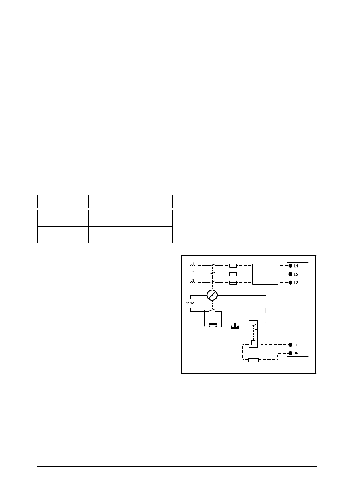
Power and ground terminals
Refer to Wiring recommendations later in this chapter.
The ground loop impedance
must conform to the
Warning
requirements of local safety
regulations.
The Drive must be grounded by
a connection capable of
carrying the prospective fault
current until the protective
device (fuse, etc) disconnects
AC supply.
the
The ground connections must
be inspected and tested at
appropriate intervals.
Figure 2–20 Locations of the power and
ground terminals
Terminal sizes and tightening torques
To avoid a fire hazard and
maintain validity of the UL
listing, adhere to the specified
Warning
tightening torques for the
power and ground terminals.
Refer to the following tables.
2-28 Installing the Drive
Unidrive LV model sizes 1 to 3 Installation Guide
Issue code: uliu1
Page 35

Drive
Power cables
20mm
3
/4 in
20mm
3
/4 in
28mm
11/16 in
Table 2–13 Mechanical data for the
Drive terminals
Model
size
1 Plug-in
2 Plug-in
3 M10 stud 15 N.m
Torque tolerance ±10%
terminals
Size
Type
terminal
block
terminal
block
Power
Torque Size
0.5 N.m
4.4 lb.inM4(Torx/
0.5 N.m
4.4 lb.inM4(Torx/
11 lb.ft
Ground
terminal
Type
slot-head
screw)
slot-head
screw)
M10 stud 15 N.m
RFI filter
Table 2–14 Mechanical data for the
RFI filter terminals
Size Power
A
B
C
D
Torque tolerance ±10%
terminals
Size
Type
Screw
terminals
Screw
terminals
M8 stud 12.6 N.m
M8 stud 12.6 N.m
Torque Size
0.7 N.m
6. lb.in
0.7 N.m
6. lb.in
9 lb.ft
9 lb.ft
Ground
terminal
Type
Screw
terminals
Screw
terminals
M8 stud 12.6 N.m
M8 stud 12.6 N.m
Torque
3 N.m
2.2 lb.ft
3 N.m
2.2 lb.ft
11 lb.ft
Torque
0.7 N.m
6. lb.in
0.7 N.m
6. lb.in
9 lb.ft
9 lb.ft
Using the gland plate and cable glands
When the gland plate(s) are not
fitted, objects less than 60mm
1
/2 in) wide can pass through
Warning
Fit the gland plate and cable glands as required.
Before fitting cable glands, push out sufficient
blanking caps from the gland plate.
Note that the IP rating of the Drive is reduced if any
holes in the gland plate are left open. The rating is
affected as follows:
Gland plate not fitted IP00
Gland plate fitted
Unused holes uncovered
Gland plate and glands fitted
Blanking caps covering unused holes
Table 2–15 Diameters of the holes in
Model
size
1 20mm
2 20mm
3 20mm
(2
the cable entry opening and
possibly make contact with live
parts inside the Drive.
IP10
IP40
the gland plate
Gland plate hole diameter
Control signal
wiring
3
/4 in
3
/4 in
3
/4 in
Unidrive LV model sizes 1 to 3 Installation Guide
Issue code: uliu1
Installing the Drive 2-29
Page 36

2.7 Wiring recommendations
Observe the wiring recommendations given in this
section. Recommendations are given separately for
the following:
Routine EMC precautions
• Recommended when strict compliance with
emission standards is not required.
• Minimized risk of disturbing adjacent
electronic equipment.
Key to symbols
Single power cable
Three-core power cable or
three single power cables
Four-core power cable
(3-phase + ground)
Ground cable
No sensitive circuits permitted
in this zone
Compliance with EMC emission
standards
• Strict compliance with emission standards.
• When the Drive is installed in a residential
area, or adjacent to sensitive electronic
equipment such as radio receivers or similar.
The details of individual installations may vary, but
details which are indicated in the recommendations
to be important for EMC must be adhered to
closely.
For further details when EMC emission requirements
are to be met, refer to the Unidrive LV EMC Data Sheet
for the size of Drive used.
Optional external
braking resistor
AC
supply
L1
L2
L3
Ground
Output 3
Output 2
Output 1
Ground
Host
controller
0V
Isolator
Contactor
Fuses or
MCB
Control cables
to the Drives
Power-ground
bus-bar
Drive
L1 L2 L3 U VW+
_
Back-plate
Enclosure
Figure 2–21 Wiring guidelines for routine EMC precautions (model sizes 1 to 3)
2-30 Installing the Drive
Unidrive LV model sizes 1 to 3 Installation Guide
Issue code: uliu1
Page 37

Routine EMC precautions (model sizes 1 to 3)
General features
1. Single power-ground bus-bar, or low-
impedance ground terminal.
2. Incoming
power ground bus-bar.
3. Connect grounds of any other circuits to the
power ground bus-bar.
4. Site ground, if required.
5. Metal back-plate, safety bonded to the power
ground bus-bar.
6. System isolator, circuit contactors and
fuses/MCB.
7. Alternative position for Drive fuses/MCB.
8. Motor-frame ground connection, if required.
9. Optional braking resistor mounted externally,
protected by a metal grille.
10. Thermal protection device to protect the
braking resistor.
AC supply ground connected to the
Routine EMC precautions
11 Use four-core cable to connect the motor to
the Drive as shown. The ground conductor in
the motor cable must be connected only to the
ground terminals of the Drive and motor; it
must not be connected directly to the powerground bus-bar.
12. If the wiring for sensitive signal circuits is to be
parallel to an unshielded motor cable (or cables
for an unfiltered power supply) for more than
1 metre (3 feet), ensure the separation is at
least 0.3m (12 in).
If the parallel run is to exceed 10 metres (30
feet), increase the separation proportionally.
For example, if the parallel run is to be
40 metres, the spacing must be 0.3 x 40 ÷ 10 =
1.2 metres.
When a motor-thermistor is used, this
constraint does not apply to the cable
connecting the thermistor to the Drive. The
motor-thermistor cable must be shielded (as
shown in Figures 3–4 and 3–5 in the User Guide).
13. Do not place sensitive signal circuits in a zone
extending 0.3m (12 in) all around the Drive.
14. If the control circuit 0V is to be grounded, this
should be done at the system controller (eg.
PLC) and not at the Drive. This is to avoid
injecting noise currents into the 0V circuit.
15. When the braking-resistor wiring is unshielded,
ensure a minimum spacing of 0.3m (12 in) from
signal wiring.
Unidrive LV model sizes 1 to 3 Installation Guide
Issue code: uliu1
Installing the Drive 2-31
Page 38

Key to symbols
AC
supply
L1
L2
L3
Ground
Single power cable
Three-core power cable or
three single power cables
Ground cable
Connection to cable armour or
shield
Maximu m length: 50mm (2 in)
Alternative safety ground
connection
Armoured or shielded cable
(3-phase + ground)
No sensitive circuits permitted
in this zone
Output 3
Output 2
Output 1
0V
Ground
Host
controller
Isolator
Contactor
Fuses or
MCB
Control cables
to the Drives
≤100mm
(4 in)
Optional external
braking resistor
5 − 10mm
13
( /4 − /8 in)
Drive
L1 L2 L3 U VW+
L1 L2 L3
RFI filter
_
Back-plate
Power-ground
bus-bar
Enclosure
Figure 2–22 Wiring guidelines for compliance with EMC emission standards (model sizes 1 and 2)
2-32 Installing the Drive
Unidrive LV model sizes 1 to 3 Installation Guide
Issue code: uliu1
Page 39

Compliance with EMC emission standards (model sizes 1 and 2)
General features
1. Single power ground bus-bar or low-impedance
ground terminal.
2. Incoming
power ground bus-bar.
3. Connect grounds of any other circuits to the
power ground bus-bar.
4. Site ground if required.
5. Metal back-plate, safety bonded to the power
ground bus-bar.
6. System isolator, circuit contactors and
fuses/MCB.
7. Alternative position for Drive fuses.
8. Optional braking resistor mounted externally,
protected and shielded by a metal grille.
9. Thermal overload device to protect the
braking resistor.
10. Alternative safety ground for the motor.
11. Motor-frame ground connection, if required.
AC supply ground connected to the
Special features for EMC
12. Drive heatsink directly grounded to the
back-plate using the metal mounting-brackets.
Ensure that the screws make direct electrical
connection to the back-plate, for example by
using screw threads tapped in the backplate.
13. RFI filter mounted at the side of the Drive.
Ensure a separation of 5 to 10mm (
from the Drive. The RFI filter casing is directly
grounded to the back-plate by the fixing
screws.
14. A shielded (screened) or steel-wire armoured
cable must be used to connect the Drive to the
motor. The shield must be bonded to the
back-plate using an uninsulated metal cableclamp. The clamp must be positioned no
further than 100mm (4 in) from the Drive.
15. Connect the shield of the motor cable to the
ground terminal of the motor frame using a link
that is as short as possible and not exceeding
50mm (2 in) in length. A full 360° termination
of the shield to the terminal housing of the
motor is beneficial.
16. Ensure the
AC supply and ground cables are at
least 100mm (4 in) from the Drive.
1
/4 to 3/8 in)
17. Avoid placing sensitive signal circuits in a zone
extending 0.3m (12 in) all around the Drive.
18. Unshielded wiring to the optional braking
resistor(s) may be used, provided the resistor is
either in the same enclosure as the Drive or the
wiring does not run external to the enclosure.
When the braking-resistor wiring is unshielded,
ensure a minimum spacing of 0.3m (12 in) from
signal wiring and the
AC supply wiring to the
RFI filters.
19. If the control circuit 0V is to be grounded, this
should be done at the host controller (eg. PLC)
and not at the Drive. This is to avoid injecting
noise currents into the 0V circuit.
Unidrive LV model sizes 1 to 3 Installation Guide
Issue code: uliu1
Installing the Drive 2-33
Page 40

Key to symbols
AC
supply
L1
L2
L3
Single power cable
Three-core power cable or
three single power cables
Ground cable
Connection to cable armour or
shield
Maximu m length: 50mm (2 in)
Alternative safety ground
connection
Armoured or shielded cable
(3-phase + ground)
No sensitive circuits permitted
in this zone
Output 3
Output 2
Output 1
0V
Ground
Host
controller
Isolator
Contactor
Fuses or
MCB
Control cables
to the Drives
150mm
(6 in)
Optional external
braking resistor
Drive
L1L2L3
L2´L3´
L1´ E´
LOAD
RFI filter
LINE
L1 L2 L3
E
UVW
_
+
≤150mm
(6 in)
Ground
Power-ground
bus-bar
Back-plate
Enclosure
Figure 2–23 Wiring guidelines for compliance with EMC emission standards (model size 3)
2-34 Installing the Drive
Unidrive LV model sizes 1 to 3 Installation Guide
Issue code: uliu1
Page 41

Compliance with EMC emission standards (model size 3)
General features
1. Single power ground bus-bar or low-impedance
ground terminal.
2. Incoming
AC supply ground connected to the
power ground bus-bar.
3. Connect grounds of any other circuits to the
power ground bus-bar.
4. Site ground if required.
5. Metal back-plate, safety bonded to the power
ground bus-bar.
6. System isolator, circuit contactors and
fuses/MCB.
7. Alternative position for Drive fuses.
8. Optional braking resistor mounted externally,
protected and shielded by a metal grille.
9. Thermal overload device to protect the
braking resistor.
10. Alternative safety ground for the motor.
11. Motor-frame ground connection, if required.
Special features for EMC
12. Drive heatsink directly grounded to the
back-plate using fixing screws. Screw threads
tapped into the back-plate must be used to
ensure that a direct electrical connection is
made. An unpainted back-plate (eg. zincplated steel) is required.
13. RFI filter mounted 150mm (6 in) from the Drive.
The RFI filter casing is directly grounded to the
back-plate by the fixing screws. Minimize the
length of cables between the Drive and
RFI filter.
14. A shielded (screened) or steel-wire armoured
cable must be used to connect the Drive to the
motor. The shield must be bonded to the
back-plate using an uninsulated metal cableclamp. The clamp must be positioned no
further than 150mm (6 in) from the Drive.
15. Connect the shield of the motor cable to the
ground terminal of the motor frame using a link
that is as short as possible and not exceeding
50mm (2 in) in length. A full 360° termination
of the shield to the terminal housing of the
motor is beneficial.
16. Ensure the
AC supply and ground cables are at
least 100mm (4 in) from the motor cable.
17. Avoid placing sensitive signal circuits in a zone
extending 0.3m (12 in) all around the Drive.
18. Unshielded wiring to the optional braking
resistor(s) may be used, provided the resistor is
either in the same enclosure as the Drive or the
wiring does not run external to the enclosure.
When the braking-resistor wiring is unshielded,
ensure a minimum spacing of 0.3m (12 in) from
signal wiring and the
AC supply wiring to the
RFI filters.
19. If the control circuit 0V is to be grounded, this
should be done at the host controller (eg. PLC)
and not at the Drive. This is to avoid injecting
noise currents into the 0V circuit.
Unidrive LV model sizes 1 to 3 Installation Guide
Issue code: uliu1
Installing the Drive 2-35
Page 42

2.8 Variations in the EMC
wiring recommendations
Control wiring
Control wiring which is connected to the Drive and
leaves the enclosure must have one of the following
additional treatments:
• Pass the control cable(s) through a ferrite
ring (part number 3225-1004). More than
one cable can pass through a ferrite ring.
Ensure the length of cable between the
ferrite ring and the Drive is not greater than
125mm (5 in).
• Use one or more cables having a separate
overall shield. Bond this shield(s) to the
back-plate using an uninsulated metal clamp.
Position the clamp not further than 100mm
(4 in) from the Drive. Do not make any
other connections to either end of the
overall shield.
Terminal block in the enclosure
The motor cable shields should be bonded to the
back-plate using uninsulated metal cable-clamps
which should be positioned as close as possible to
the terminal block. Keep the length of power
conductors to a minimum and ensure that all
sensitive equipment and circuits are at least 0.3m
(12 in) away from the terminal block.
From the Drive
Interruptions to the motor cable
The motor cable should ideally be a single piece of
shielded or armoured cable having no interruptions.
In some situations it may be necessary to interrupt
the cable, as in the following examples:
Connecting the motor cable to a terminal block
in the Drive enclosure
Fitting a motor isolator switch for safety when
work is done on the motor
In these cases the following guidelines should be
followed.
Back-plate
Enclosure
To the motor
(Refer to Key to symbols in Figure 2–22)
Figure 2–24 Connecting the motor cable to
a terminal block in the enclosure
2-36 Installing the Drive
Unidrive LV model sizes 1 to 3 Installation Guide
Issue code: uliu1
Page 43

Using a motor isolator-switch
The motor cable shields should be connected by a
very short conductor having a low inductance. The
use of a flat metal coupling-bar is recommended;
conventional wire is not suitable.
The shields should be bonded directly to the
coupling-bar using uninsulated metal cable-clamps.
Keep the length of the exposed power conductors
to a minimum and ensure that all sensitive
equipment and circuits are at least 0.3m (12 in)
away.
The coupling-bar may be grounded to a known
low-impedance ground nearby, for example a large
metallic structure which is connected closely to the
Drive ground.
Isolator
From the
Drive
Coupling bar
(If required)
To the
motor
(Refer to Key to symbols in Figure 2–22)
Figure 2–25 Connecting the motor cable to
an isolator switch
2.9 Signal connections
The signal connections to be made depend on the
method of control to be used. Refer to Chapter 2
Getting Started, Chapter 3 Setting up the Drive and
Appendix C Signal Connections in the User Guide.
Unidrive LV model sizes 1 to 3 Installation Guide
Issue code: uliu1
Installing the Drive 2-37
Page 44

2-38 Installing the Drive
Unidrive LV model sizes 1 to 3 Installation Guide
Issue code: uliu1
Page 45
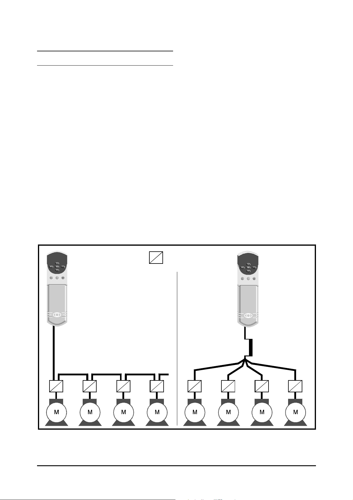
A Motor Connections
A.2 Multiple motors
Open-loop only
A.1 Cable length
It is not recommended that a Drive is operated with
a motor-cable length greater than that specified in
the table in Planning the installation in Chapter 2. If
this is unavoidable, it is recommended that a
sinusoidal filter is used to prevent the
components from entering the motor cable.
Sinusoidal filters are available from specialist filter
suppliers.
PWM switching
If the Drive is to control more than one motor, make
connections as shown in Figure A–1. The maximum
cable lengths given in the table in Chapter 2 Installing
the Drive apply to the total length of cable from the
Drive to the farthest motor.
It is recommended that each motor is connected
through a protection relay since the Drive cannot
protect each motor. For star connection, a
sinusoidal filter or an output inductor must be
connected as shown in Figure A–1, even when the
cable lengths are less than the maximum permissible.
For details, of inductor sizes refer to a Drive Centre
or distributor listed at the end of the User Guide.
Motor protection
relay
Chain connection (preferred) Star connection
Figure A–1 Connecting motors in parallel
Unidrive LV model sizes 1 to 3 Installation Guide
Issue code: uliu1
Inductor
Motor connections A-1
Page 46

A-2 Motor connections
Unidrive LV model sizes 1 to 3 Installation Guide
Issue code: uliu1
Page 47
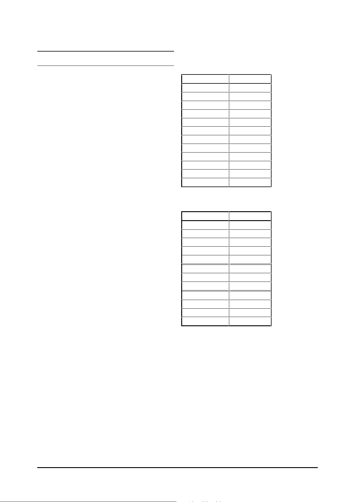
B UL Listing Information
FLC (A)
2.1
2.8
3.8
5.6
9.5
12
16
25
34
46
60
74
FLC (A)
2.1
2.8
3.8
4.0
4.3
12.0
14.2
14.2
28.0
28.0
32.0
35.0
Table B–1 Maximum continuous output
current for standard and VTC
models
The Drive conforms to UL listing requirements only
when the following are observed:
• The Drive is installed in a type 1 enclosure, or
better, as defined by UL50
• UL-listed fuses class RK1 600V
AC supply
the
AC are used in
• Class 1 60/75°C (140/167°F) copper wire only
is used in the installation
• The ambient temperature does not exceed
40°C (104°F) when the Drive is operating
• The terminal tightening torques specified in
the table in Terminal sizes and tightening
torques in Chapter 2 Installing the Drive are
used
2.1 AC supply specification
The Drive is suitable for use in a circuit capable of
delivering not more than 5000
Amperes at 268V
AC RMS maximum.
RMS symmetrical
2.2 Maximum continuous
output current
The Drive models are listed as having the maximum
continuous output currents (FLC) shown in Tables
B–1 and B–2 (see Appendix C Data for details).
Model
UNI 1201
UNI 1202
UNI 1203
UNI 1204
UNI 1205
UNI 2201
UNI 2202
UNI 2203
UNI 3201
UNI 3202
UNI 3203
UNI 3204
Table B–2 Maximum continuous output
current for LFT models
Model
UNI 1201 LFT
UNI 1202 LFT
UNI 1203 LFT
UNI 1204 LFT
UNI 1205 LFT
UNI 2201 LFT
UNI 2202 LFT
UNI 2203 LFT
UNI 3201 LFT
UNI 3202 LFT
UNI 3203 LFT
UNI 3204 LFT
Unidrive LV model sizes 1 to 3 Installation Guide
Issue code: uliu1
UL listing 2-1
Page 48

2-2 UL listing
Unidrive LV model sizes 1 to 3 Installation Guide
Issue code: uliu1
Page 49

C Data
C.1 Drive
Power and current ratings
The input current is affected by the supply voltage
and impedance. Therefore, to aid the selection of
cables and fuses, the values of Maximum
continuous input current stated are for the
worst-case condition.
The values of maximum current for models 1201 to
1205 are stated for a 200V
times the kVA of the Drive, with 2% negative
phase-sequence imbalance and a typical motor load.
The values of maximum current for models 2201 to
2203 and 3301 to 3304 are stated for a 200V
AC supply having a 5kA short-circuit capability and a
2% negative phase-sequence imbalance.
The values of Typical input current are stated
for a balanced 200V
short-circuit capability; these values are given to aid
calculations for power flow and power loss.
AC supply rated at ten
AC supply having a 5kA
Unidrive LV and Unidrive VTC LV
(at 40°°C ambient temperature)
Model Nominal
rating
kW HP 3kHz 4.5kHz 6kHz 9kHz 12kHz
UNI 1201 0.37 kW 0.5 2.1 A 2.1 A 2.1 A 2.1 A 2.1 A 2.4 A 4.0 A
UNI 1202 0.55 kW 0.75 2.8 A 2.8 A 2.8 A 2.8 A 2.8 A 3.5 A 6.0 A
UNI 1203 0.75 kW 1.0 3.8 A 3.8 A 3.8 A 3.8 A 3.8 A 4.6 A 8.0 A
UNI 1204 1.1 kW 1.5 5.6 A 5.6 A 5.6 A 5.6 A 4.5 A 6.5 A 10.0 A
UNI 1205 2.2 kW 3.0 9.5 A 9.5 A 8.5 A 7.0 A 5.5 A 8.6 A 12.5 A
UNI 2201 3.0 kW 4.0 12.0 A 12.0 A 12.0 A 12.0 A 11.7 A 10.8 A 13.9 A
UNI 2202 4.0 kW 5.0 16.0 A 16.0 A 16.0 A 14.2 A 11.7 A 14.3 A 16.9 A
UNI 2203 5.5 kW 10.0 25.0 A 21.7 A 18.2 A 14.2 A 11.7 A 19.8 A 27.0 A
UNI 3201 7.5 kW 15.0 34.0 A 34.0 A 34.0 A 28.0 A 23.0 A 26.0 A 28.0 A
UNI 3202 11 kW 20.0 46.0 A 46.0 A 40.0 A 32.0 A 26.6 A 39.0 A 43.0 A
UNI 3203 15 kW 25.0 60.0 A 47.0 A 40.0 A 32.0 A 26.7 A 53.0 A 56.0 A
UNI 3204 22 kW 30.0 74.0 A 56.0 A 46.0 A 35.0 A 28.0 A 78.0 A 84.0 A
Maximum permissible
continuous output current
Typical
input
current
Maximum
current
cont.
input
Unidrive LV model sizes 1 to 3 Installation Guide
Issue code: uliu1
Data C-1
Page 50

Unidrive LV and Unidrive VTC LV
(at 50°°C ambient temperature)
Model Maximum permissible
3kHz 4.5kHz 6kHz 9kHz 12kHz
UNI 1201 2.1 A 2.1 A 2.1 A 2.1 A 2.1 A
UNI 1202 2.8 A 2.8 A 2.8 A 2.8 A 2.8 A
UNI 1203 3.8 A 3.8 A 3.8 A 3.8 A 3.3 A
UNI 1204 5.6 A 5.6 A 5.1 A 4.0 A 3.3 A
UNI 1205 6.9 A 5.9 A 5.1 A 4.0 A 3.3 A
UNI 2201 12.0 A 12.0 A 12.0 A 11.6 A 9.7 A
UNI 2202 16.0 A 16.0 A 14.7 A 11.6 A 9.7 A
UNI 2203 20.0 A 17.3 A 14.7 A 11.6 A 9.7 A
UNI 3201 34.0 A 34.0 A 28.0 A 21.0 A 17.9 A
UNI 3202 44.0 A 36.0 A 31.0 A 24.0 A 20.6 A
UNI 3203 44.0 A 36.0 A 31.0 A 24.0 A 20.9 A
UNI 3204 50.0 A 41.0 A 34.0 A 20.0 A 23.0 A
continuous output current
Unidrive LFT LV
(at 9kHz
UNI 1201LFT 0.37 kW 0.5 2.1 A 2.1 A 2.1 A 3.1 A
UNI 1202LFT 0.55 kW 0.75 2.8 A 2.8 A 2.8 A 3.2 A
UNI 1203LFT 0.75 kW 1.0 3.8 A 3.8 A 3.3 A 5.5 A
UNI 1204LFT 1.1 kW 1.5 5.6 A 4.0 A 3.3 A 8.4 A
UNI 1205LFT 2.2 kW 3.0 9.5 A 4.3 A 3.3 A 9.5 A
UNI 2201LFT 3.0 kW 4.0 12.0 A 12.0 A 11.0 A 13.7 A
UNI 2202LFT 4.0 kW 5.0 16.0 A 14.2 A 11.0 A 16.3 A
UNI 2203LFT 5.5 kW 10.0 25.0 A 14.2 A 11.0 A 24.3 A
UNI 3201LFT 7.5 kW 15.0 34.0 A 28.0 A 21.0 A 34.0 A
UNI 3202LFT 11 kW 20.0 46.0 A 32.0 A 24.0 A 46.0 A
UNI 3203LFT 15 kW 25.0 60.0 A 33.0 A 24.0 A 59.0 A
UNI 3204LFT 22 kW 30.0 74.0 A 35.0 A 26.0 A 74.0 A
PWM switching frequency)
Model Nominal
rating
kW HP Standard
Maximum permissible output current Nominal AC
duty-cycle
operation
at 40°°C
Continuous
operation
at 40°C
Continuous
operation
at 50°°C
supply current
C-2 Data
Unidrive LV model sizes 1 to 3 Installation Guide
Issue code: uliu1
Page 51

AC supply requirements
Current ratings
Voltage: 200V ~ 240V ±10%
No. of phases: 3
Maximum supply imbalance:
2% negative phase sequence (equivalent to 3%
voltage imbalance between phases)
Frequency range: 48 to 62 Hz
Line reactors
Line reactors reduce the risk of damage to the Drive
that could result from severe phase unbalance or
disturbances on the supply network. As a result of
the following, for example...
• Power factor correction equipment
connected close to the Drive
• Large
• Direct-on-line started motor(s) connected
...excessive peak current may flow in the input
power circuit of the Drive. Such disturbances may
cause nuisance tripping or in extreme cases, failure
of the Drive.
When any of the following model sizes...
UNI1201
UNI1202
UNI1203
UNI1204
UNI1205
...are used on an
conditions described above exists, OR the
is rated at more than ten times the current rating of
the Drive, it is strongly recommended that a line
reactor of 2% reactance is included between the
AC supply and the Drive. Model sizes 1205 and larger
have an internal
require a line reactor except under extreme supply
conditions.
Caution
DC Drives having no or ineffective line
reactors connected to the supply
to the supply. When any of these motors
are started, a dip is produced in excess of
20% of the actual
AC supply where one of the
DC-bus choke; these models do not
RFI filters (for EMC purpose)
do not give adequate
protection against these
conditions.
AC supply voltage
AC supply
Continuous: Not less than the continuous current
rating of the Drive
Repetitive peak: Not less than twice the continuous
current of the Drive.
Motor requirements
Number of phases: 3
Voltage: 200V ~ 240V ±10%
Temperature, humidity
and cooling method
Ambient temperature range:
0°C to 50°C (32°F to 122°F). Output current
de-rating must be applied at ambient temperatures
between 40°C (104°F) and 50°C (122°F) (absolute
maximum).
Minimum temperature at power-up: –10°C (14°F)
Cooling method: Forced convection
Maximum humidity:
95% non-condensing at 40°C (104°F)
Storage temperature range:
–40°C to 50°C (–40°F to 122°F)
Maximum storage time: After each 12 months, the
capacitors will need re-forming; refer to the supplier
of the Drive.
Altitude
Altitude range: 0 to 4000m (13000 ft), subject to
the following conditions:
1000m to 4000m (3300 ft to 13000 ft) above
sea level: De-rate the maximum output current
from the specified figure by 1% per 100m
(330 ft)
Vibration
Tested to ≤0.5g as specified in IEC 68–2–34
For three-phase Drives, three individual reactors, or
a single three-phase reactor should be used. Each
Drive must have its own reactor(s).
Unidrive LV model sizes 1 to 3 Installation Guide
Issue code: uliu1
Data C-3
Page 52

Ingress protection
EN50081-1
radiated
No
No
No
Immunity
Gland plate(s) not fitted: IP00
Gland plate(s) fitted; cable glands not fitted: IP10
Gland plate(s) fitted; cable-glands fitted:
IP40, NEMA 1
Overall dimensions
H Height including surface mounting
brackets
W Width
D Projection forward of panel when
surface mounted
F Projection forward of panel when
through-panel mounted
R Projection rear of panel when
through-panel mounted
Dimension Model size
123
H
W
D
F
R
366mm
3
14
/
95mm
3
3
/4 in
200mm
7
7
/8 in
120mm
1
4
/4 in
80mm
1
3
/8 in
8
366mm
14
190mm
7 1/2 in
200 mm
7 7/8 in
120mm
4 1/4 in
80mm
3 1/8 in
368mm
3
/
8
1
14
/4 in
375mm
14 3/4 in
260mm
10 1/
120mm
4 1/4 in
140mm
5 1/2 in
4
Weights
Compliance with immunity standards does not
depend on installation details. Drives meet
EN50082–2 (generic immunity standard for the
industrial environment) and the following
specifications from the IEC61000–4 group (derived
from IEC801):
Part 2, Electrostatic discharge: Level 3
Part 3, Radio frequency field: Level 3
Part 4 Transient burst:
Level 4 at the control terminals
Level 3 at the power terminals
Part 5, Surge (at the
AC supply terminals)
(as specified by EN50082–2 informative annex):
Level 4 line-to-ground
Level 3 line-to-line
Part 6, Conducted radio frequency: Level 3
Emission
Compliance with emission standards depends on
rigorous adherence to the installation guidelines,
including the use of the specified RFI filter in the
supply circuit. Compliance also depends on the
PWM switching frequency used in the output stage
of the Drive, and the length of the motor cable. For
full details, refer to the Unidrive EMC Data Sheet which
can be obtained from a Drive Centre or distributor
listed at the end of the User Guide.
When installed according to the instructions the
Drive can meet the emission requirements of
CENELEC generic emission standards, as follows:
AC
Model size kg lb
1
2
3
4 8.8
817
22 49
Electromagnetic compatibility (EMC)
This is a summary of the EMC performance of the
Drive. For full details, refer to the Unidrive LV EMC
Data Sheet which can be obtained from a Drive
Centre or distributor listed at the end of the User
Guide.
C-4 Data
Unidrive
size
EN50081-1
conducted
1 Restricted
motor cable
length
2 Restricted
motor cable
length
3No
Unidrive LV model sizes 1 to 3 Installation Guide
EN50081-2
conducted
Yes Yes
Yes Yes
Yes Yes
Issue code: uliu1
EN50081-2
radiated
Page 53

The optional RFI filter specified below must be used:
Drive model Use RFI filter...
Type Part number
UNI 1201
UNI 1202
UNI 1203
UNI 1204
UNI 1205
UNI 2201
UNI 2202
UNI 2203
UNI 3201
UNI 3202
UNI 3203
UNI 3204
A
A
A
A
A
B
B
B
C
C
D
D
4200–0010
4200–0010
4200–0010
4200–0010
4200–0010
4200–0027
4200–0027
4200–0027
4200–1051
4200–1051
4200–1071
4200–1071
Power Drive Systems standard
EN61800–3
The Drive meets the immunity requirements of
EN61800–3 irrespective of the environment in which
it is operating.
The emission requirements of this standard are also
met depending on the environment category, as
shown in the table below.
EN61800–3 defines the following:
• The first environment as one that
includes domestic premises. It also includes
establishments directly connected without
intermediate transformers to a low-voltage
power supply network which supplies
buildings used for domestic purposes.
• The second environment is one that
includes all establishments other than those
directly connected to a low-voltage power
supply network which supplies buildings
used for domestic purposes.
• Restricted distribution is defined as a
mode of sales distribution in which the
manufacturer restricts the supply of
equipment to suppliers, customers or users
who separately or jointly have technical
competence in the EMC requirements of the
application of Drives.
Note
If a Power Drive System is included as part
of equipment covered by a separate EMC
product standard, the EMC standard for the
complete equipment applies.
Power Drive Systems standard EN61800–3
Model size Environment category
First environment Second environment
UNI 1201 ~ UNI 1205
(Rated input current
of Drive <25A)
UNI 2201, UNI 2202
(Rated input current
of Drive <25A)
UNI 2203
(Rated input current
of Drive >25A)
UNI 3201 ~ UNI 3204
(Rated input current
of Drive >25A)
Restricted distribution only: specified RFI filter required No RFI filter required *
Restricted distribution only: specified RFI filter required No RFI filter required *
Specified RFI filter required No RFI filter required *
Specified RFI filter required No RFI filter required *
RFI filter(s) recommended where sensitive electronic systems are operating nearby.
Unidrive LV model sizes 1 to 3 Installation Guide
Issue code: uliu1
Data C-5
Page 54
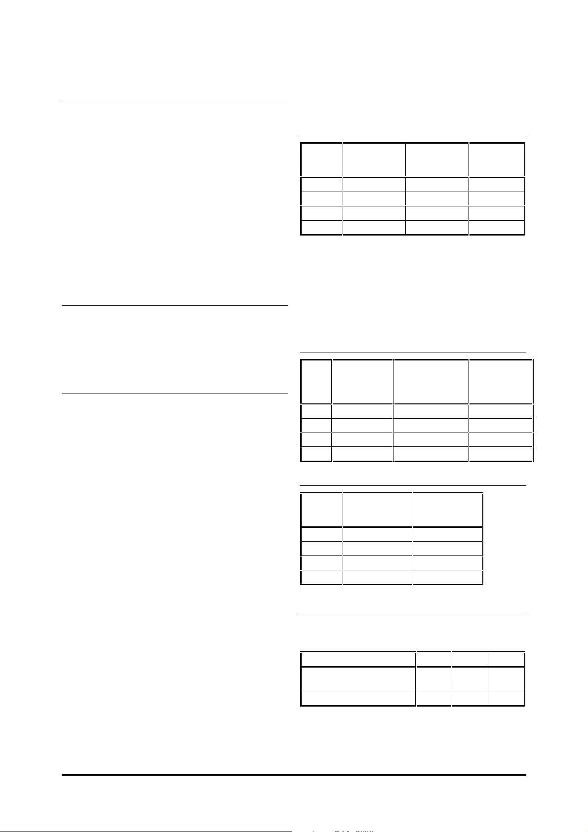
Frequencies and speed
Max.
continuous
current
10 A
27 A
50 A
75 A
Type
Maximum
ambient
temperature at
rated current
A
50 °C (122°F)
B
50 °C (122°F)
C
50 °C (122°F)
D
50 °C (122°F)
Power
dissipation at
rated current
25 W
40 W
60 W
100 W
PWM switching frequency
Unidrive LV and Unidrive VTC LV: 3kHz nominal
(selectable up to 12kHz)
Unidrive LFT LV: 9kHz nominal (selectable from
3kHz to 12kHz)
Maximum output frequency (open-loop): 2000Hz
Maximum speed (closed-loop): 30 000
RPM
Speed regulation:
(open-loop): 1 ~ 2%
(closed-loop): 0.01%
Speed control range:
(open-loop): >50:1
(closed-loop): >1000:1
Starts per hour
C.2 Optional RFI filters
Ratings
Type Part number
A
B
C
D
4200–0010
4200–0027
4200–1051
4200–1071
Maximum current overload:
150% of rated current for 1 minute in a 10 minute
period.
Voltage (phase-to-phase and phase-to-ground):
480V +10%
Ingress
protection
IP20
IP20
IP 00
IP 00
By electronic control: unlimited
By interrupting the
AC supply:
model sizes 1 and 2: ≤20
model sizes 3 and 4: ≤10
Accuracy and resolution
The following data applies to the Drive only; it does
not include the performance of the source of the
control signals.
Open-loop frequency resolution...
Preset frequency reference: 0.1Hz
Precision frequency reference: 0.001Hz
Open-loop frequency accuracy...
Preset frequency reference: 0.03Hz or 0.01% of
the reference, whichever is the larger value
Precision frequency reference: 0.0001Hz or
0.01% of the reference, whichever is the larger
value
Closed-loop speed resolution
Unidrive LV and Unidrive LFT LV only...
Preset speed reference: 1
Precision speed reference: 0.01 RPM
Analog input 1: 0 RPM *
* The speed-loop algorithm ensures that the
steady-state speed can change by infinitely
small amounts in response to changes in the
reference from these inputs.
Closed-loop speed accuracy
Unidrive LV and Unidrive LFT LV only...
Preset or precision speed reference:
0.00016
RPM or 0.01% of the reference,
whichever is the larger value
RPM
AC supply frequency: 48 to 62 Hz
Temperature
Part number
4200–0010
4200–0027
4200–1051
4200–1071
Case
temperature
rise at rated
current
<30°C (86°F)
<40°C (104°F)
<40°C (104°F)
<40°C (104°F)
Power dissipation
Type Part number
A
B
C
D
4200–0010
4200–0027
4200–1051
4200–1071
Ground leakage current
Ground-leakage current when the AC supply is 400V
at 50Hz is as follows:
Condition
Balanced supply phase-tophase and phase-to-ground
One phase disconnected 25mA 35mA 210mA
For other AC supply voltages and frequencies, scale
the values of leakage current proportionally.
AB
3.4mA 4.4mA 33mA
C to D
C-6 Data
Unidrive LV model sizes 1 to 3 Installation Guide
Issue code: uliu1
Page 55

Discharge resistors
A and B: 330KΩ in a star network between phases,
with the star point connected by a 1MΩ resistor to
ground.
C to D: 10MΩ between each phase and ground.
The discharge resistors are fitted internally.
Overall dimensions
Type Part Dimension
number
A
4200–0010 396mm
B
4200–0027 406mm
C
4200–1051 330mm
D
4200–1071 330mm
HWD
15
16 in
13 in
13 in
9
/16 in
50mm
115/16 in
75mm
15
2
/
190mm
1
7
/2 in
190mm
1
7
/2 in
114.5mm
41/2 in
114.5mm
in
16
41/2 in
145mm
511/16 in
145mm
511/16 in
Weights
Type Part number kg lb
A
B
C
D
4200–0010 2 5
4200–0027 2.7 6
4200–1051 7.4 16
4200–1071 8 18
Unidrive LV model sizes 1 to 3 Installation Guide
Issue code: uliu1
Data C-7
Page 56

C-8 Data
Unidrive LV model sizes 1 to 3 Installation Guide
Issue code: uliu1
 Loading...