

Page 1
............
............
............
............
............
............
............
............
............
............
............
............
............
............
............
............
............
............
............
............
............
............
............
............
............
............
............
............
............
............
............
............
Unidrive Servo &
Unimotor
product data
The performance matched AC Servo
solution for all applications
Page 2

2
Page 3

servo drive
Drive Overview 4
Introduction to Macros 7
Drive Technical Specification 12
Connections 16
Drive Installation 19
Electro Magnetic Compatibility (EMC) & Radio 24
Frequency Interference (RFI)
servo motor
Motor Overview 26
Motor Technical Specification 27
Motor Installation 32
Accessories 34
servo drive & motor
combinations
Torque Speed Curves & Tables 42
Servo Sizing Software 48
motion intelligence
Options 50
Typical Applications 54
3
Chapter 1
Chapter 2
Chapter 3
Chapter 4
..........
..........
..........
..........
Page 4
drive overview
Connectivity
UD73 - Profibus DP
UD74 - Interbus S
UD77 - DeviceNet
UD75 - CT Net
UD76 - Modbust +
UD71 - RS232/485
HMI - Operator Interfaces
Feedback
Standard - Encoder
UD53 - Resolver
UD52 - Sin/cos encoder
Unimotor
Brushless AC Servo motors to 70Nm
On request:
- Brushless >70NM-1850Nm
- Asynchronous >70NM-2500Nm
Motor accessories: - cables, fan
cowlings, brakes, planetary geared
motors
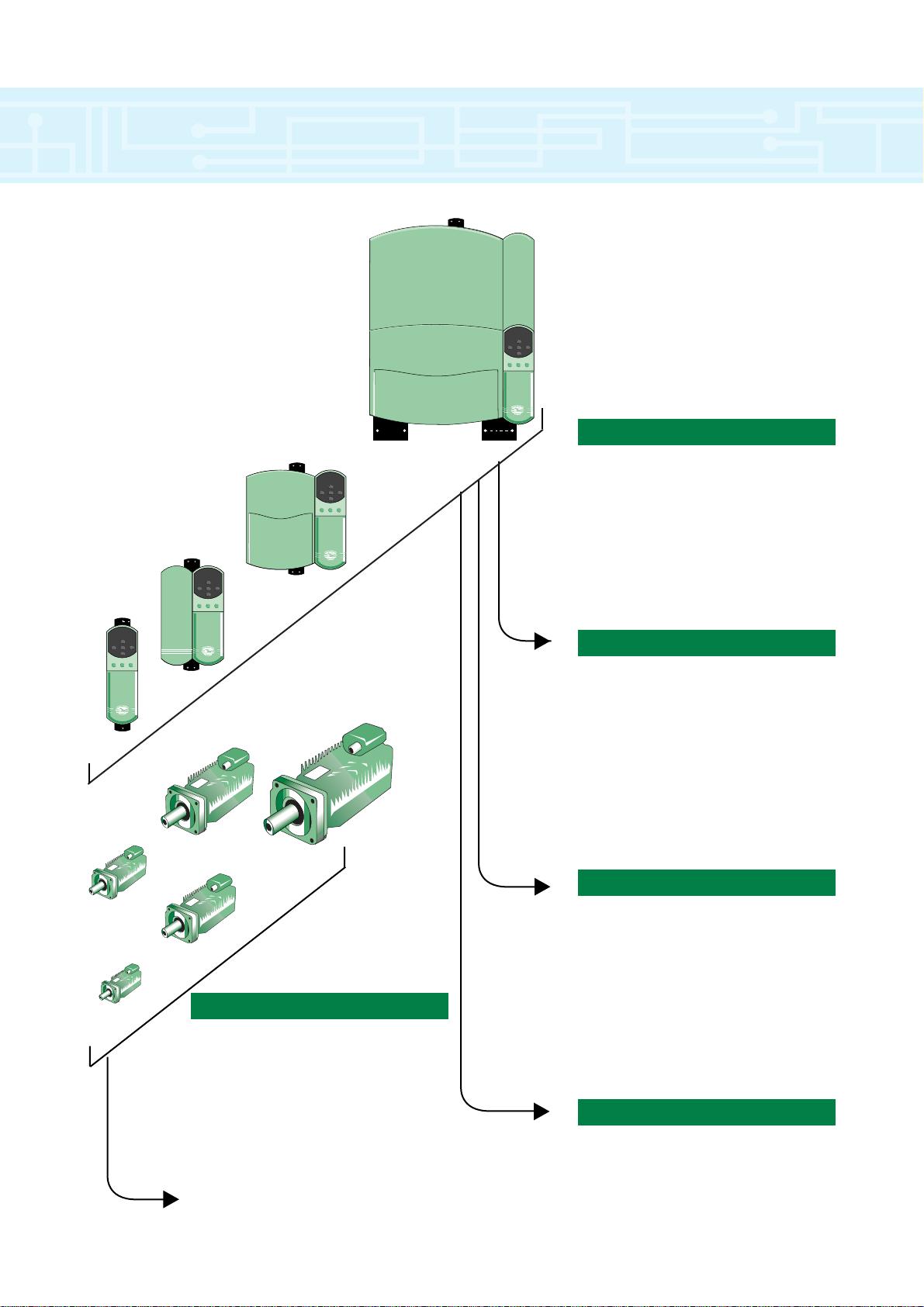
Unidrive Servo
& Unimotor
The complete multi purpose
Servo package with
high flexibility
& functionality
Model size 3
Model size 2
Model size 1
Model size 4
Motion Intelligence
UD70 - Applications module
UD78 - High performance servo
UD50 - Extended I/O
UD51 - 2nd Encoder
Unisoft - Programming software
SYPT - Systems programming tool
CTSS - Servo sizing software tool
Power Range 380-480V
Size 1 - 0.75 to 4kW
Size 2 - 5.5 to 11kW
Size 3 - 15 to 37kW
Size 4 - 45 to 110kW
Size 5 - >110kW
Line regeneration capability
4
75
95
115
142
190
Page 5

Unidrive
The Unidrive is an advanced AC drive for use with
AC brushless permanent magnet servo motors. The
Unidrive’s set up can be easily and quickly changed
from the on-board keypad, a remote keypad, or
through UniSoft, a Windows™based configuration
software tool.
Sizes
There are five physical sizes comprising 26
different models ranging from 1NM to 2500 NM*. The
drive is designed for stand alone as well as
coordinated systems applications. There are hundreds
of configurable functions in 20 logically organised
menus. All functions are factory defaulted to typical
values to facilitate easy set-up.
Parameters
The Unidrive’s most commonly used parameters
are stored in Menu 0. This menu is defaulted with
those parameters which are typically accessed, but
the user may map any of the drive’s other
parameters to this menu for easier access. This
approach means easy access for those parameters
the user selects.
Flexibility
In addition Unidrive has many other of embedded
configurable functions which are easily adapted for
virtually any application. Some of these configurable
functions include items such as assignable I/O,
autotune, encoder feedback, frequency and direction
pulse signal input and output, axis limit control, ratio
control, electronic holding brake, S-ramps, position
control and many others.
Technology
Many of these important product features would not
be possible without the use of advanced technology in
the Unidrive. The drive employs advanced
microprocessor technology which controls all drive
functions including input to the inverter ASIC
(Application Specific Integrated Circuit) which
synthesises an adjustable carrier frequency PWM
(Pulse Width Modulation) output. The ASIC output
controls the IGBT (Insulated Gate Bipolar Transistor)
inverter section. All printed circuit boards are
manufactured using surface mount technology.
Regeneration
The Regeneration mode is used for four-quadrant
operation. A Drive can be operated in Regeneration mode
only when it is connected to other Drive(s) operating in
one of the other (motoring) modes.
Regeneration mode allows the following:
●
AC supply to be fed from the Regeneration Drive to
the Drive(s) that are controlling the motor
● Regenerated power to be returned to the AC supply
by the Regeneration Drive instead of being dissipated
in braking resistors
Regeneration Module Control Mode
▼
drive overview
* For ratings above 65NM please consult your local Drive/Application centre
5
Regenerating
Unidrive
AC Supply
Filter
and
Start
Circuit
+
DC Bus
—
Motoring
Unidrive
AC
Motor
Page 6

Key Features
General Features
●
Coast & Ramp to Stop modes
●
8 Preset speeds & Ramps
●
3 Skip frequencies
●
S Ramp
●
Motorised potentiometer
●
Internal braking transistor as standard
●
Encoder input as standard
●
Programmable security code
●
Bright two line LED display
Advanced Features
●
Position control
●
Digital lock
●
Mains dip ride through
●
Frequency slaving
●
Catch a spinning motor
●
Programmable logic functions
●
Orientation
Performance Features
●
336µs speed loop sample time
●
176µs current loop sample time
●
16 bit speed loop
●
12 bit current loop
●
Dynamic injection/braking
●
Fast current loop with PI control
Flexibility Features
●
Speed reference selector
●
Full I/O programmability
●
Unisoft
●
Well structured menu system
●
Encoder I/P
●
Programmable logic functions
●
Configurable menu zero
●
Programmable thresholds
●
Resolver feedback
●
Sin/cos feedback
●
High speed communications
●
Applications module
●
High performance module
Ease of Use Features
●
Macros
●
Bright two line LED display
●
Cloning module
●
Unisoft
Maintenance Features
●
Clock
●
Full internal protection & diagnostics
●
Last ten trips stored
●
Programmable security code
●
Common control board
●
Pluggable terminals
drive overview
6
Page 7

introduction to macros
7
Introduction
The Unidrive’s more than 700 parameters are
organised so that similar parameters are grouped within
the same menu. For example, Menu 1 holds the
parameters associated with the selection of a speed
reference. Menu 2 holds parameters associated with
the selection of acceleration and deceleration rates etc.
Menu zero
This menu holds parameters that are quick access
duplicates of the most used advanced parameters.
Categories:
0.0 Configuration
0.01 – 0.02 Speed limits
0.03 – 0.06 Ramps
Speed reference selection
Current limit
0.07- 0.09 PID gains (closed loop)
0.10 – 0.13 Monitoring
0.14 – 0.17 Jog reference
Ramp mode selector
Stop and torque mode selectors
0.18 – 0.19 S-ramp
0.20 – 0.23 Skip bands
0.24 – 0.26 Analogue input modes
0.27 – 0.34 Miscellaneous
0.35 Keypad reference monitoring
0.36 – 0.38 Serial communications
Parameter displayed at power up
0.39 – 0.41 Spinning motor
Autotune
PWM switching frequency
0.42 – 0.47 Motor parameters
0.48 Operating mode selection
0.49 – 0.50 Status information
Menu 1 Frequency / speed reference selection
Frequency / speed limits
Skip frequencies / speeds
Menu 2 Acceleration and deceleration ramps
Ramp selection, enable selected
Braking mode selection
S-ramp
Menu 3 Speed indications
Speed loop PID gain
Speed sensing thresholds
Frequency slaving
Hard speed reference
Encoder set up
Menu 4 Current monitoring
Current limiting in speed control
Current loop gains
Torque control
Motor protection
Menu 5 Motor monitoring
Motor ratings
Autotune
PWM switching frequency
Menu 6 Drive sequencer
Auto-start
AC supply loss
Jog time
Limit switches
Injection braking
Synchronise to a spinning motor
Keypad enable
Run-time log
Electricity cost
Menu 7 Analogue I/O
Temperatures
Menu 8 Digital I/O
Menu 9 Programmable logic
Motorised potentiometer
Binary-sum logic
Menu 10 Status and diagnostic information
Process generated trips
UD78 power supply indicator
Menu 11 Menu 0 assignments
Scale factors
Initial parameters displayed
Serial communications
Drive information
Menu 12 Programmable comparators
Menu 13 Position control
Menu 14 PID controller
Menu 15 Regeneration
Menu 16 Small Option Module
Menu 17 Large Option Module
Menu 18 User parameters LOM
Menu 19 User LOM
Menu 20 UD70 only
Menu Overview
Page 8
8
introduction to macros
Unidrive operation can be simplified by using preconfigured application macros. These macros are held in
the internal memory of the drive and are user selectable.
Macro summary
Macro 1 – Easy Mode
Easy mode defines the most commonly used
features with only 10 parameters. These parameters
are numbered 0.01 to 0.10
Macro Function
0 Default mode
1 Easy mode
2 Motorised potentiometer
3 Preset speeds
4 Torque control
5 PID macro
6 Axis Limit control
7 Hoist control/brake release
8 Digital Lock
0.01 1.07 Minimum Speed
0.02 1.06 Maximum Speed
0.03 2.11 Acceleration time
0.04 2.21 Deceleration time
0.05 1.14 Reference select
0.06 4.07 Current limit
0.07 3.10 Proportional gain
0.08 3.11 Integral gain
0.09 3.12 Derivation gain
0.10 3.02 Speed feedback
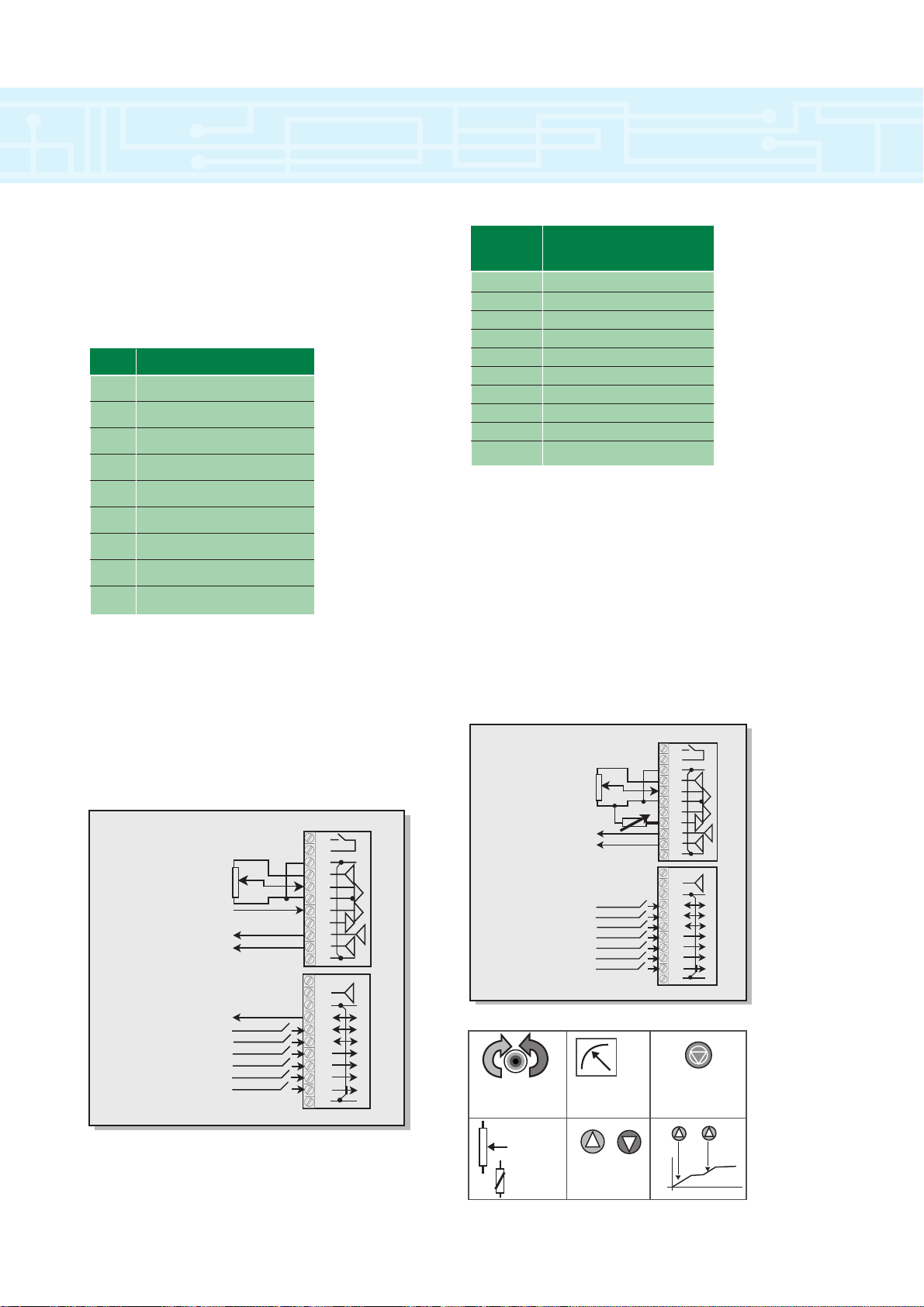
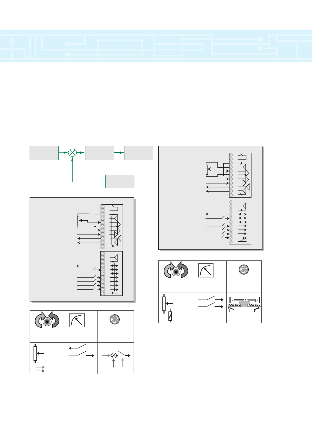
Macro 2 – Motorised Potentiometer
With this function it is possible to emulate a
motorised potentiometer within the Unidrive by simply
supplying two logic input signals to increase or
decrease the “potentiometer”. The output of the
“potentiometer” may be routed to control any of the
drive’s non-bit parameters such as speed, torque or
current limit. The function may be configured to reset
upon power cycling or to memorise its value.
Menu 0
Parameter
Param. Description
When a Macro is not enabled, the drive operates in a default
configuration (EURO USA)
Drive Connections
Analog Ch 1
0-10v DC
Analog Ch 2
4-20mA Input
Speed Output
Load Output
At Speed Output
Drive Reset Input
Jog Input
Run Forward Input
Run Reverse Input
Analog 1/2 Select Input
External Trip Input
1
2
3
4
5
6
7
8
9
10
11
21
22
23
24
25
26
27
28
29
30
31
Drive Connections
Analog Ch 1
0-10v DC
Thermistor
Speed Output
Load Output
Motorised Pot Up Input
Drive Reset Input
Motorised Pot Down Up
Run Forward Input
Run Reverse Input
An/Mot Pot Select Input
External Trip Input
Run Forward
& Reverse
Speed
& Current
x 2
1
2
3
4
5
6
7
8
9
10
11
21
22
23
24
25
26
27
28
29
30
31
External
Reset Input
x 1
0-10V DC
Thermistor
Motorised pot
Increase &
Decrease
Page 9
introduction to macros
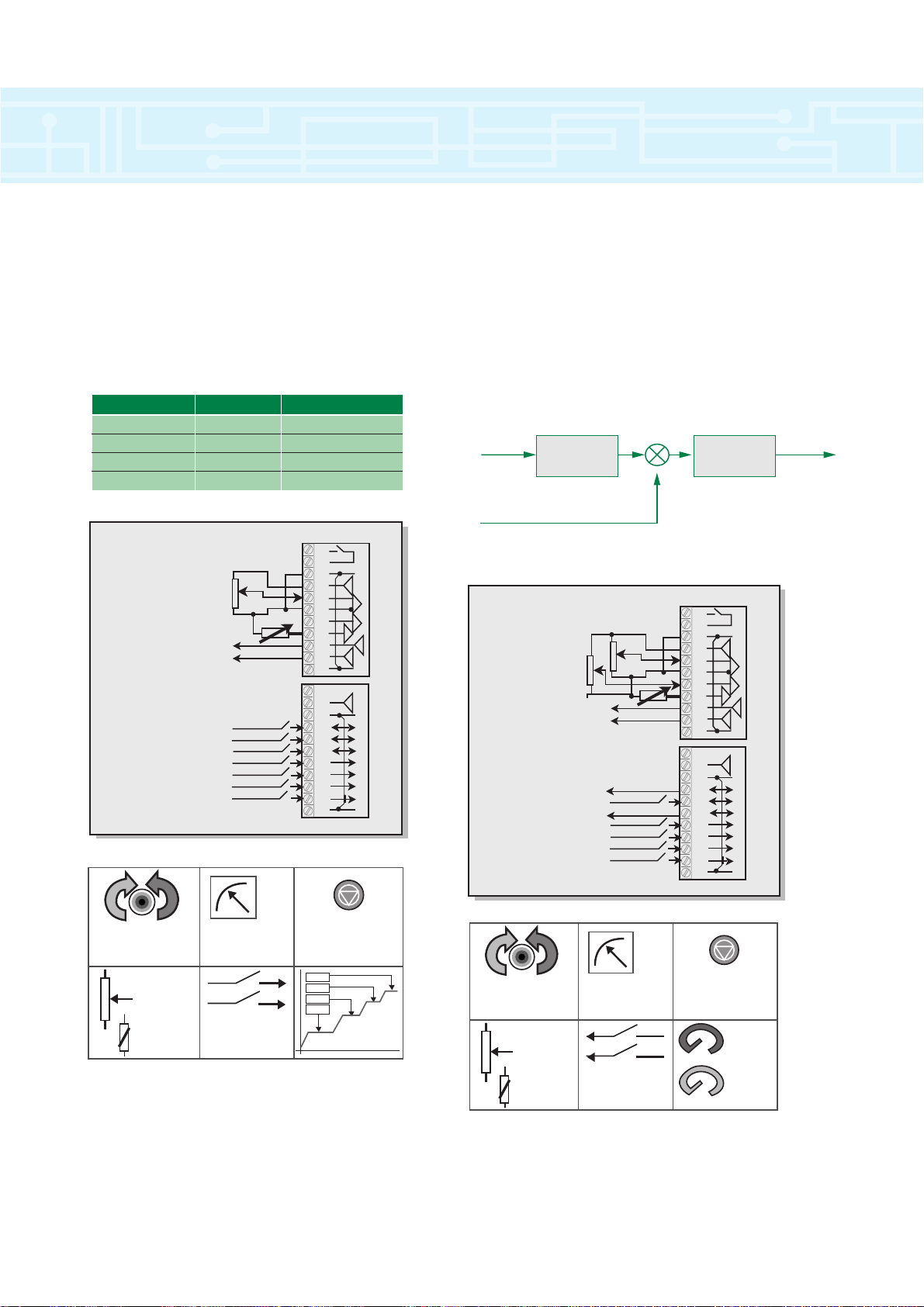
Terminal 24 Terminal 26 Speed
Open Open As set in Pr 0.25
Open Closed As set in Pr 0.26
Closed Open As set in Pr 0.27
Closed Closed As set in Pr 0.28
Macro 3 – Preset Speeds
By using this macro up to four preset frequencies /
speeds can be used. Preset values must be
programmed into individual parameters. Frequency /
speed selection is done by activating terminal 29 and
putting a binary combination on terminals 24 and 26.
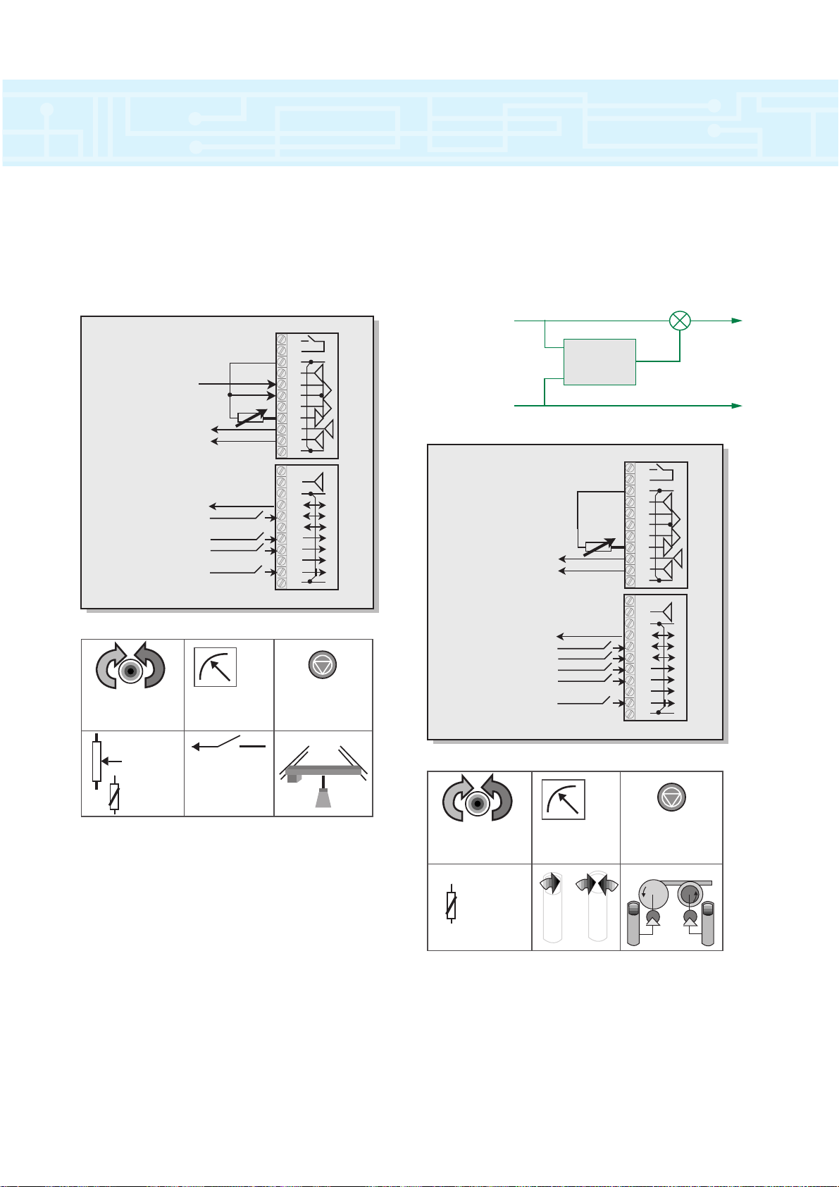
Macro 4 – Torque control
When this macro is selected a drive can be operated
in Speed or Torque control by using terminal 29.
If in Speed control mode, speed is maintained
independent of load within the limits of the drive. In
Torque control mode the drive will attempt to reach the
speed set point but only with the torque available as
defined by the torque reference signal.
Torque/Current
PI (Current)
Current Feedback (torque component)
Torque Ref. Post Ramp
Ref
9
Drive Connections
Analog Ch 1
0-10v DC
Thermistor
Speed Output
Load Output
Preset Select 1 Input
Drive Reset Input
Preset Select 2 Input
Run Forward Input
Run Reverse Input
An/Preset Select Input
External Trip Input
1
2
3
4
5
6
7
8
9
10
11
21
22
23
24
25
26
27
28
29
30
31
Drive Connections
Torque Ref.
Speed Ref.
Thermistor
Speed Output
Load Output
Drive Speed Output
Drive Reset Input
Min. Speed Output
Run Forward Input
Run Reverse Input
Speed/Torque Select Input
External Trip Input
1
2
3
4
5
6
7
8
9
10
11
21
22
23
24
25
26
27
28
29
30
31
x 2
Run Forward
& Reverse
Speed
& Current
x 1
0-10V DC
Thermistor
2 Inputs
for 4
Preset Speeds
External
Reset Input
P1 and 1
P1 and 2
P1 and 3
P1 and 4
Run Forward
& Reverse
0-10V DC
Thermistor
x 1
x 2
Speed
& Current
2 Outputs
for A1 Speed
& At Min.Speed
External
Reset Input
0%
100%
0%
100%
RPM
(Speed)
Amps
(Torque)
Page 10
10
introduction to macros
Macro 6 – Axis Limit control
Using this macro enables two digital inputs to be
re-programmed so providing limit switch lockout for
axis position control systems. The drive would normally
be run from a +/- 10v reference and controlled forward
/ backwards from this. If a limit switch level is reached
the drive will be forced to stop independent of the
speed setting.
Macro 5 – PID control
This macro configures the drive to control a motor
with reference to PID control signal. In PID control, the
error resulting from differences between the PID
feedback and PID reference is passed through a limiter,
a scaling stage and finally the error is added to the
frequency / speed signal.
Setpoint
Source
PID
Output
Source
Feedback
Source
Drive Connections
Torque Ref.
Main Ref.
PID Reference
PID Feedback
Speed Output
Load Output
Drive At Speed Output
Drive Reset Input
Run Forward Input
Run Reverse Input
PID Enable Input
External Trip Input
x 2
1
2
3
4
5
6
7
8
9
10
11
21
22
23
24
25
26
27
28
29
30
31
Drive Connections
Torque Ref.
Main Ref.
PID Reference
PID Feedback
Speed Output
Load Output
Drive At Speed Output
Drive Reset Input
Run Forward Input
Run Reverse Input
PID Enable Input
External Trip Input
Run Forward
& Reverse
x 1
0-10V DC
Thermistor
Speed
& Current
2 Inputs
for Forward &
Reverse limits
x 2
1
2
3
4
5
6
7
8
9
10
11
21
22
23
24
25
26
27
28
29
30
31
External
Reset Input
Run Forward
& Reverse
0-10V DC
PID Ref
PID F/bk
x 1
Speed
& Current
Input for
PID Enable &
At Speed O/P
PID Ref
External
Reset Input
P
I
D
PID F/bk
PID
Enable
Page 11
introduction to macros
Macro 8 – Digital Lock
The digital lock macro enables a drive to be
operated so that it will lock two motor shafts together
pulse for pulse.
Macro 7 – Brake control
This macro essentially allows the control of an
external brake. The brake is released when the drive is
running and there is current in the motor.
11
Drive Connections
Speed Input
from PLC
Thermistor
Speed Output
Load Output
Brake Release Output
Drive Reset Input
Run Forward Input
Run Reverse Input
External Trip Input
Run Forward
& Reverse
Speed
& Current
x 2
1
2
3
4
5
6
7
8
9
10
11
21
22
23
24
25
26
27
28
29
30
31
External
Reset Input
Reference Counts
Accumultor
Feedback Counts
Drive Connections
Thermistor
Speed Output
Load Output
Drive At Speed Output
Drive Reset Input
Relative Jog Input
Run Forward Input
Run Reverse Input
Enable Input
+/- Error
1
2
3
4
5
6
7
8
9
10
11
21
22
23
24
25
26
27
28
29
30
31
Feed Forward
Feedback
x 1
0-10V DC
Thermistor
Brake Release
Output
Run Forward
& Reverse
Thermistor
only
Speed
& Current
Relative Jog
Input
x 2
External
Reset Input
Take Up
M
Capatan
M
Page 12

12
AC supply requirements
380V to 480V ±10%, 3-phase, 48 to 62 Hz
Maximum supply imbalance: 2% negative phase sequence
(equivalent to 3% voltage imbalance between phases)
Line reactors
When one of the following model sizes...
UNI 1401, UNI 1402, UNI 1403, UNI 1404
....is used on an AC supply of 175kVA or larger, it is
recommended that a line reactor of 2% reactance is
included between the AC supply and the Drive. Model
sizes 1405 and larger have an internal dc-bus choke.
A line reactor reduces the risk of damage to the Drive
resulting from severe disturbances on the supply network.
Temperature, humidity and cooling method
Ambient temperature range:
–10°C to 50°C (14°F to 122°F). Output current de-rating
may apply at high ambient temperatures.
Cooling method: Natural convection
Maximum humidity: 95% non-condensing at 40°C (104°F)
Storage temperature range: –40°C to 50°C (–40°F to 122°F)
Maximum storage time: 12 months
Altitude
Altitude range: 0 to 4000m (13000 ft), subject to the
following conditions:
1000m to 4000m (330 feet to 13000 ft) above sea level:
de-rate the maximum output current from the specified
figure by 1% per 100m (330 ft)
Vibration
Maximum vibration:²0.5g as specified in IEC 68–2–61; 1982
Ingress protection
Gland plate(s) not fitted: IP00
Gland plate(s) fitted; cable glands not fitted: IP10
Cable-glands fitted; glands fitted: IP40, NEMA 1
Accuracy and Resolution
The following data applies to the Drive only; it does not
include the performance of the source of the control signals.
Output-frequency accuracy:² ±0.1%
Output-frequency resolution: ² ± 0.01
RPM
Starts per hour
By electronic control: unlimited
By interrupting the AC supply:
model sizes 1 and 2: ² 20, model sizes 3 and 4: ² 10
Nominal Maximum permissible continuous output current Nominal
rating AC
supply
current
@380V @460V 3kHz ✝ 4.5kHz 6kHz 9kHz 12kHz
UNI 1401 0.75 kW 1.0 HP 2.1 A 2.1 A 2.1 A 2.1 A 2.1 A 3.1 A
UNI 1402 1.1 kW 1.5 HP 2.8 A 2.8 A 2.8 A 2.8 A 2.8 A 3.2 A
UNI 1403 1.5 kW 2.0 HP 3.8 A 3.8 A 3.8 A 3.8 A 3.8 A 5.5 A
UNI 1404 2.2 kW 3.0 HP 5.6 A 5.6 A 5.6 A 5.6 A 4.5 A 8.4 A
UNI 1405 4.0 kW 5.0 HP 9.5 A 9.5 A 8.5 A 7.0 A 5.5 A 9.5 A
UNI 2401 5.5 kW 7.5 HP 12.0 A 12.0 A 12.0 A 12.0 A 11.7 A 13.7 A
UNI 2402 7.5 kW 10.0 HP 16.0 A 16.0 A 16.0 A 14.2 A 11.7 A 16.3 A
UNI 2403 11.0 kW 15.0 HP 25.0 A 21.7 A 18.2 A 14.2 A 11.7 A 24.3 A
UNI 3401 15.0 kW 25.0 HP 34.0 A 34.0 A 34.0 A 28.0 A 23.0 A 34.0 A
UNI 3402 18.5 kW 30.0 HP 40.0 A 40.0 A 37.0 A 28.0 A 23.0 A 39.0 A
UNI 3403 22.0 kW 30.0 HP 46.0 A 46.0 A 40.0 A 32.0 A 26.6 A 46.0 A
UNI 3404 30.0 kW 40.0 HP 60.0 A 47.0 A 40.0 A 32.0 A 26.7 A 59.0 A
UNI 3405 37.0 kW 50.0 HP 70.0 A 56.0 A 46.0 A 35.0 A 28.0 A 74.0 A
UNI 4401 45.0 kW 75.0 HP 96.0 A 96.0 A 88.0 A 70.0 A 96.0 A
UNI 4402 55.0 kW 100.0 HP 124.0 A 104.0 A 88.0 A 70.0 A 120.0 A
UNI 4403 75.0 kW 125.0 HP 156.0 A 124.0 A 105.0 A 80.0 A 151.0 A
UNI 4404 90.0 kW 150.0 HP 180.0 A 175.0 A 145.0 A 110.0 A 173.0 A
UNI 4405 110.0 kW 150.0 HP 202.0 A 175.0 A 145.0A 110.0 A 190.0 A
UNI 5401 160.0 kW 200.0 HP 300.0 A 240.0 A
Power and Current ratings
40°C (104°F)
ambient
Model
drive technical specifications
✝ Peak current: up to 175% of the rated current for 4 seconds
✝ Factory setting
Page 13

13
drive technical specifications
Frequencies and
speed
PWM switching
frequency:
3kHz nominal (selectable
up to 12kHz)
Maximum speed
30 000 RPM
Speed regulation: 0.01%
Model Nominal Maximum total power dissipation
rating
@380V @460V 3kHz 4.5kHz 6kHz 9kHz 12kHz
UNI 1401 0.75kW 1.0HP 80 W 80 W 90 W 90 W 90 W
UNI 1402 1.1kW 1.5HP 90 W 90 W 100 W 100 W 110 W
UNI 1403 1.5kW 2.0HP 100 W 110 W 110 W 120 W 130 W
UNI 1404 2.2kW 3.0HP 130 W 130 W 140 W 150 W 150 W
UNI 1405 4.0kW 5.0HP 180 W 190 W 190 W 190 W 170 W
UNI 2401 5.5kW 7.5HP 210 W 230 W 250 W 280 W 310 W
UNI 2402 7.5kW 10HP 270 W 290 W 310 W 320 W 310 W
UNI 2403 11.0kW 15HP 400 W 380 W 360 W 330 W 310 W
UNI 3401 15.0kW 25HP 570 W 620 W 670 W 660 W 630 W
UNI 3402 18.5kW 30HP 660 W 720 W 730 W 660 W 630 W
UNI 3403 22.0kW 30HP 730 W 800 W 770 W 730 W 700 W
UNI 3404 30.0kW 40HP 950 W 830 W 790 W 740 W 710 W
UNI 3405 37.0kW 50HP 1090 W 990 W 920 W 850 W 800 W
UNI 4401 45kW 75HP 1460 W 1610 W 1630 W 1530 W
UNI 4402 55kW 100HP 1910 W 1780 W 1670 W 1560 W
UNI 4403 75kW 125HP 2370 W 2130 W 2030 W 1860 W
UNI 4404 90kW 150HP 2640 W 2890 W 2700 W 2470 W
UNI 4405 110kW 150HP 2970 W 2910 W 2720 W 2490 W
UNI 5401 160kW 200HP 5000 W
Dissipation
50°C (122°F) Maximum permissible
ambient continuous output current
Model 3kHz 4.5kHz 6kHz 9kHz 12kHz
UNI 1401 2.1 A 2.1 A 2.1 A 2.1 A 2.1 A
UNI 1402 2.8 A 2.8 A 2.8 A 2.8 A 2.8 A
UNI 1403 3.8 A 3.8 A 3.8 A 3.8 A 3.3 A
UNI 1404 5.6 A 5.6 A 5.1 A 4.0 A 3.3 A
UNI 1405 6.9 A 5.9 A 5.1 A 4.0 A 3.3 A
UNI 2401 12.0 A 12.0 A 12.0 A 11.6 A 9.7 A
UNI 2402 16.0 A 16.0 A 14.7 A 11.6 A 9.7 A
UNI 2403 20.0 A 17.3 A 14.7 A 11.6 A 9.7 A
UNI 3401 34.0 A 34.0 A 28.0 A 21.0 A 17.9 A
UNI 3402 40.0 A 34.0 A 28.0 A 21.0 A 17.9 A
UNI 3403 44.0 A 36.0 A 31.0 A 24.0 A 20.6 A
UNI 3404 44.0 A 36.0 A 31.0 A 24.0 A 20.9 A
UNI 3405 50.0 A 41.0 A 34.0 A 26.0 A 23.0 A
UNI 4401 95.0 A 85.0 A 75.0 A 60.0 A
UNI 4402 105.0 A 85.0 A 75.0 A 60.0 A
UNI 4403 135.0 A 105.0 A 85.0 A 65.0 A
UNI 4404 180.0 A 150.0 A 125.0 A 95.0 A
UNI 4405 190.0 A 150.0 A 125.0 A 95.0 A
Page 14

14
Dynamic Braking
Resistor Connections
The external braking resistor should be connected
to the Unidrive terminals labelled (+) and (-) on the
terminal strip on Unidrive size 1 & 2 or the stud
connections on Unidrive size 3 & 4. The resistor must
be thermally protected in the unlikely event that the
braking transistor fails. This thermal device must either
disconnect the input AC power to the Inverter or
disconnect the resistor from the circuit. Please contact
the a Drive Centre for additional application information.
Custom Resistor Values
The resistor ohmic value is based on the torque
required to stop the motor (and connected load) in the
time dictated by the application. The first equation to
be solved is the torque required knowing the required
stop time.
T = J x N
(Ft - Lb) or
T = 2¹ J x N
(Nm)
t
d x 307 td x 60
Where:
J= Total Inertia (Lb-Ft
2
or Kgm2)
N = Motor Max. Speed (RPM)
t
d = Decel Time (Sec.)
T = Torque (Ft-Lb or Nm)
The torque required must be equal or less than 1.5
x motor/drive capability.
HP
(brake) = T x N
or
P(kW) = T x N
5250 30
The ohmic value of the resistor can now be
calculated using the following formula:
R = (V
b)
2
or
R = (Vb)
2
HP(brake) x 746 P(kW)
Where:
V
b = Bus voltage level when braking
= 750 VDC
Minimum Values
The calculated minimum ohmic value is limited by
the braking transistor supplied in the Unidrive being
used. The following is a list of the minimum values.
Average Power Dissipation
The average power dissipated in the resistor for
intermittent operation is then simply the number of
watts dissipated per stop times the duty cycle (D).
Where:
D = t
d
td + toff
In order to use this formula for average power
dissipation, the brake resistor must be off long enough
for the temperature of the resistor to return to ambient
temperature between braking cycles. Also, the
maximum on time (or decel time) should not exceed
the peak capabilities of the power resistor. Typically, a
power resistor has the capability of dissipating 10
times rated wattage for 5 to 10 seconds.
Peak Power Rating
The peak power handling ability of the resistor
must meet or exceed the following:
PPK = (Vb)2/R
Unidrive Size 1 40 Ohms
Unidrive Size 2 40 Ohms
Unidrive Size 3 10 Ohms
Unidrive Size 4 5 Ohms
MODEL MINIMUM VALUE
drive technical specifications
Page 15

Protection
DC Bus Undervoltage Trip 350 VDC
DC Bus Overvoltage Trip 830 VDC
MOV Voltage Transient Protection 160 Joules, 1400 Volts Clamping
(Line to Line & Line to Ground)
Drive Overload Trip Current overload value is exceeded.
Programmable to allow up to 175% of Drive Current for one minute.
Instantaneous Overcurrent Trip 215% of Drive rated current
Phase Loss Trip DC bus ripple threshold exceeded
Overtemperature Trip Drive heatsink temperature exceeds 95°C
Short Circuit Trip Protects against output phase fault
Ground Fault Trip Protects against output phase to ground fault
Motor Thermal Trip Electronically protects the motor from overheating due to
Loading conditions
15
drive technical specifications
Page 16

Status Relay 1 Normally open contacts
1 Dry contact output pole 1/2 5A, 240 VAC resistive
Drive OK (default)
2 Status Relay 1
Dry contact output pole 2/2
3 Circuit Common
0 VDC Analogue reference
4 +10 VDC ± 1% Voltage tolerance
User supply for external analogue signal device 10 mA output current (current limit protected)
5 Analogue Input 1 (non-inverting input) Bipolar ±10 VDC
Programmable Differential Analogue Input 100k½ input impedance
Analogue Speed Reference 1 (default) 12-bit plus sign resolution, ² 2mS sampling period OL
6 Analogue Input 1 (inverting input) <45 Oµs C.L.
Programmable Differential Analogue Input
7 Analogue Input 2 Programmable: ±10 VDC (default), 4-20mA,
Programmable Single-ended Analogue Input 20-4mA, 0-20mA inputs,
Analogue Speed Reference 2 (default) 100k½ input impedance
10-bit plus sign resolution
² 2mS sampling period
8 Motor Thermistor Input
Programmable Single-ended Analogue Input
9 Analogue Output 1 Programmable: ±10 VDC @ 10mA (max) (default)
Programmable Single-ended Analogue Output 4-20mA, or 0-20mA
Output Frequency (open loop default) 1k½ minimum load resistance
Speed Feedback (closed loop default) 10-bit plus sign resolution, 8mS update period
Short circuit protected
10 Analogue Output 2
Programmable Single-ended Analogue Output
Torque Output (default)
11 Circuit Common
0 VDC Analogue reference
21 OV Common
22 +24 VDC Voltage Tolerance: ±10%
User Supply Nominal Output: 200 mA
Overload Output: 240 mA with current foldback
protection
23 Circuit Common
0 VDC Digital reference
24 Programmable Logic I/O F1 Output Mode:
Output: At speed (open loop) User-defined: Negative or positive logic
At zero speed (closed loop) Negative logic (default)
Push-pull output, 0 - +24 VDC
100mA max output, 120mA overload current
Input Mode:
User-defined: Positive logic (V > +15 VDC)
or negative logic (V < +5 VDC) (default)
Voltage range: 0 - +24 VDC
3.2 mA max load at +24 VDC
25 Programmable Logic I/O F2
Input: Drive reset (default)
26 Programmable Logic I/O F3
Input: Jog (default)
27 Programmable Logic Input F4 User-defined: Positive logic (V > +15 VDC)
Latched Run Forward (default) or negative logic (V < +5 VDC) (default)
Voltage range:
0 - +24VDC, 3.2 mA max load @ +24 VDC
28 Programmable Logic Input F5
Latched Run Reverse (default)
29 Programmable Logic Input F6
Local (default)/Remote
30 Logic Input: Drive Enable (closed loop)
External Trip (open loop)
31 Circuit Common
0 VDC digital reference
Control Inputs and Outputs
TERMINAL I/O TYPE & FUNCTION RATING
NOTE: There are no terminals numbered 12, 13...., 20 on the Unidrive
connections
16
Page 17
connections
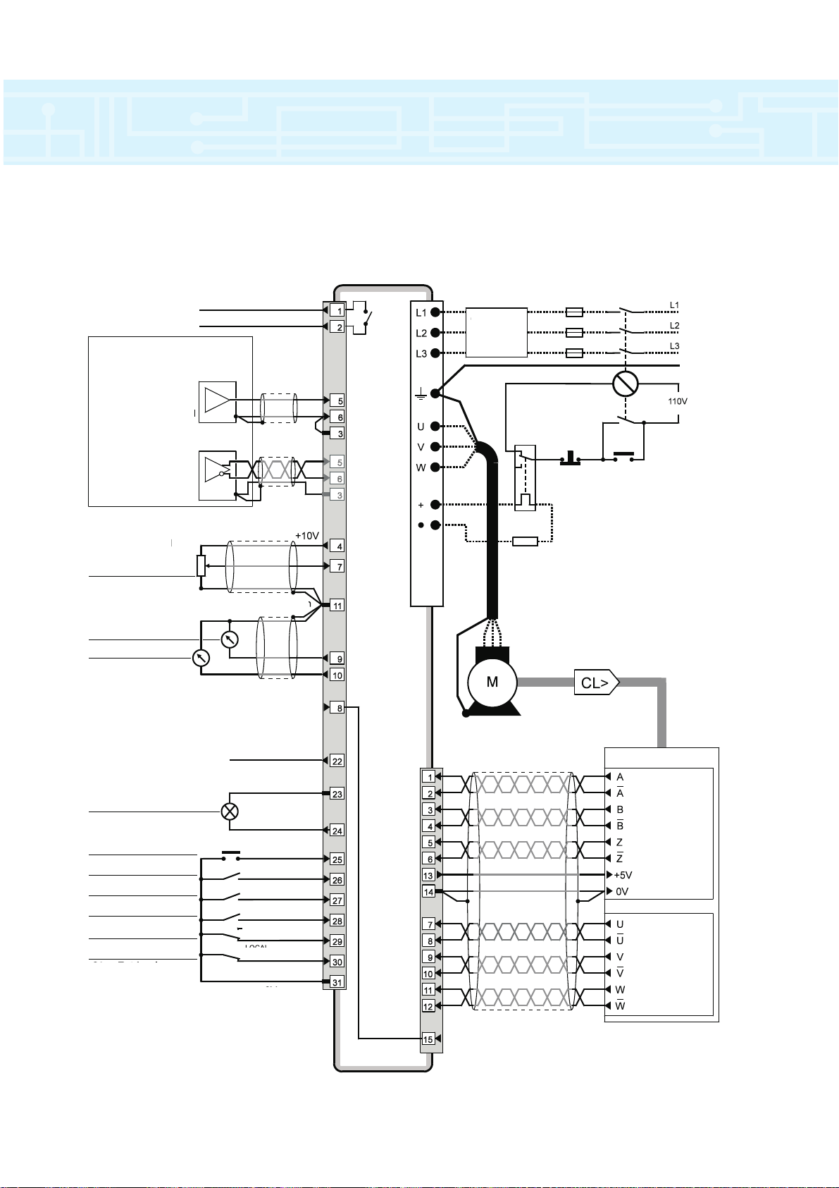
17
Typical power and default signal connections for speed
control in terminal mode
Status relay
Drive normal
Connections for
single-ended input
signal
Connections for
differential input
signal
Signal
connector
Power
terminals
Analog frequency/speed
reference 1 (remote)
Analog
frequency/speed
reference 2 (local)
SPEED
TORQUE
Analog input 3
Motor thermistor
RESET
JOG SELECT
RUN FORWARD
RUN REVERSE
LOCAL/REMOTE
DRIVE ENABLE
REMOTE
OV common
OV common
OV common
OV common
OV common
Optional
RFI filter
Thermal
protection
device
Stop
Braking resistor
Encoder
Incremental
signal
connections for
all encoders
communication
signal
connectiona for
servo-encoders
Encoder
connector
15-way
D-type
Start/
Reset
+24V
LOCAL
Page 18
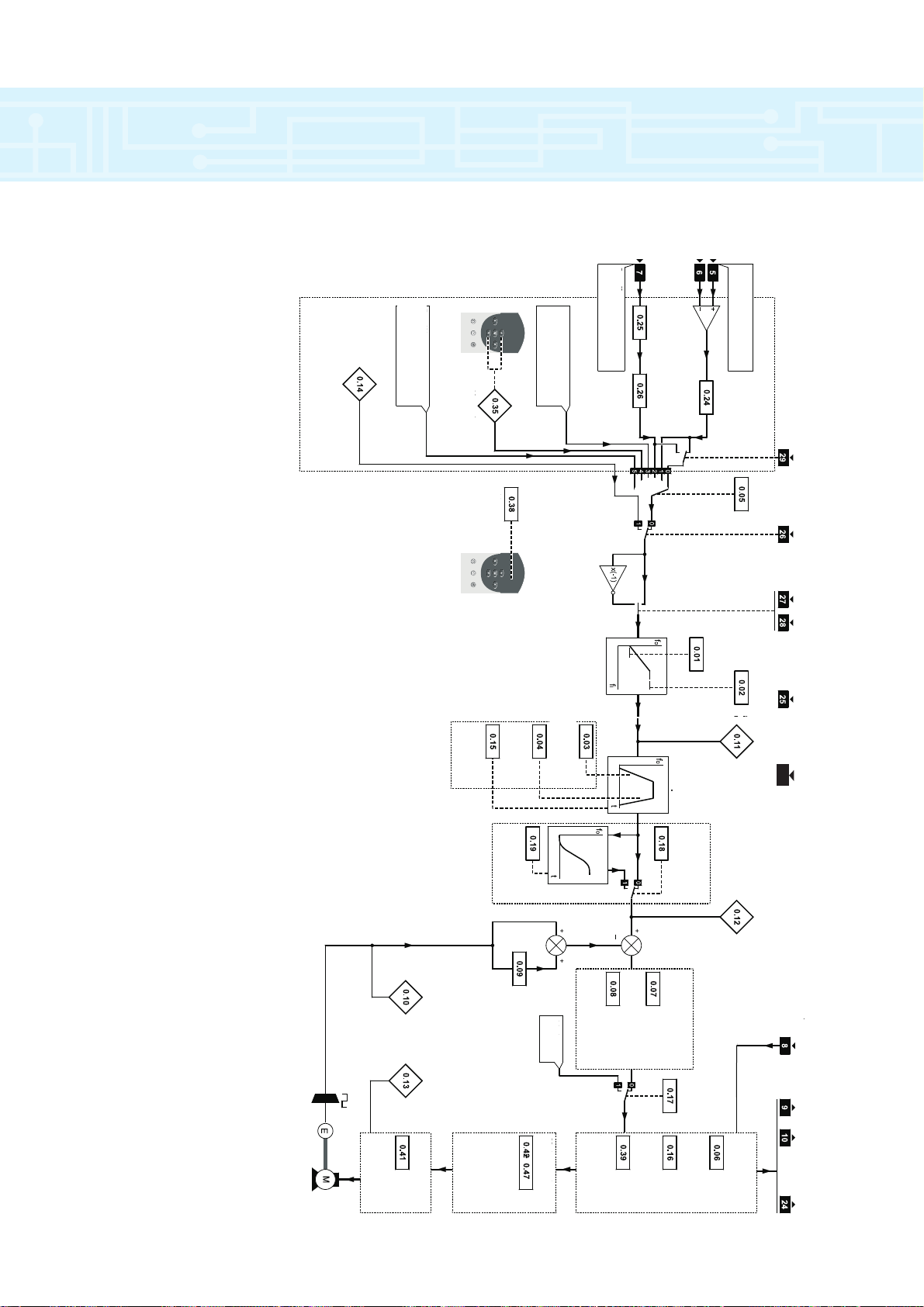
connections
AT ZERO
SPEED
Reference
selector
Menu 0 logic diagram
Speed-loop PID gains
Power stage
Motor control
Jog
reference
Keypad
reference
Reference
selector
Precision reference (not
used with Menu 0)
Preset references
(not used with Menu 0)
Speed reference 1
(remote)
Analog input 1
mode selector
All parameters are shown at their default setting
Minimum
speed
Maximum
speed
initial
parameter
displayed
Speed-loop
proportional
gain
Speed-loop
integral gain
Speed-loop
derivative
gain
Current
limit
Stop mode
selector
Torque
mode
selector
Synchronize to
a spinning
motor
No. of poles
Rated voltage
Rated speed
Rated current
Rated
frequency
PWM switching
frequency
Menu4
S-ramp
S-ramp
enable
Speed reference 2
(local)
Analog input 2
destination
select
Analog input 2
mode select
Acceleration
rate
Deceleration
rate
Ramp mode
selector
S-ramp
da/dt limit
Post-ramp
speed
reference
Motor parameters
THERMISTOR SPEED
TORQUE
Reference selection
Ramps
LOCAL/
REMOTE
JOG
SELECT
RUN
FORWARD
RUN
REVERSE
RESET
DRIVE
ENABLE
Motor
active-current
Motor
speed
Pre-ramp
speed
reference
30
18
Page 19

drive installation
➀ Consult Drive Centre for Filter details.
Panel Wiring Guidelines for Routine EMC Precautions
Panel Wiring Guidelines for Compliance with EMC Emission Standards
19
Optional braking resistors as required for the Drives
External: Mount on top surface of enclosure.
Internal: Mount in top part of enclosure.
Drives
Ensure minimum
clearances are
respected.
System controller
Locate as required.
Signal cables
Plan for all signal
cables to be routed at
least 300mm (12in)
distant from any
power cable.
Power cables
AC supply isolator,
contactor, and
fuses or MCBs
Locate as required.
³100mm
(4in)
³5mm
(…in)
Location of overload
protection device
³100mm
(4in)
Location
of optional
terminal
block
Alternative
location of
fuses or
MCBs
Locate as
required.
³5mm
(…in)
Back-plate
Enclosure
Optional braking resistors as required for the Drives
External: Mount on top surface of enclosure.
Internal: Mount in top part of enclosure.
Location of overload
protection device
Alternative location
of fuses or MCBs
Drives and
RFI filters
Ensure minimum
clearances are
respected.
System controller
Locate as required.
Signal cables
Plan for all signal
cables to be routed at
least 300mm (12in)
distant from any power
cable.
RFI filters
Install a separate RFI
filter for each Drive.
Power cables
AC supply isolator,
contactor, and
fuses or MCBs
Locate as required.
Locate as required.
³5mm
(…in)
³100mm
(4in)
³5mm
Alternative location of
fuses or MCBs
Locate as required.
(…in)
150mm
(6in)
Back-plate
Location
of optional
terminal
block
Enclosure
³5mm
(…in)
Page 20

Model size 1
Model size 2
Model size 3
Model size 4
Panel
Panel
LFA
H
C
G
LFA
C
G
E
E
Panel
LF
A
C
G
E
E
H
C
E1
E1
Panel
E3
E2
L
FA
G
E2
E3
A 345 345 345 716
[13.56] [13.56] [13.56] [28.19]
C 47.5 95 187.5 250
[1.88] [3.75] [7.38] [9.81]
E 16.5 16.5
[.63] [.63]
E1 17
[.63]
E2 65
[2.56]
E3 143.5
[5.63]
F 368 368 368 743
[14.25] [14.25] [14.25] [29.25]
G 95 190 375 500
[3.75] [7.50] [14.75] [19.69]
H 200 200 260 260
[7.88] [7.88] [10.25] [10.25]
L 335 335 335 700
[13.19] [13.19] [13.19] [27.56]
Mounting 6.5 [.16]clearance or
hole diam.
1
/
4
UNF M6 thread
Model Size 1 2 3 4
Dimension
➀
Surface Mounting
➀ Dimensions in mm and [inches].
drive installation
20
Page 21

drive installation
21
A 345 345 345 717.5
[13.56] [13.56] [13.56] [28.25]
B 295 295 287 650
[11.63] [11.63] [11.31] [25.56]
C 86.5 182 358 482
[3.38] [7.19] [14.13] [19]
D1313
(0.5) (0.5)
D1 16 17
[.63] [ .63]
D2 7 7.5
[.25] [.31]
D3 3.5
[.13]
E 16.5
[.13]
E1 131.5 192
[5.19] [7.56]
E2 69 130
[2.69] [5.13]
E3 16.5 65
[.63] [2.56]
F 364 364 364 743
[14.31] [14.31] [14.31] [29.25]
G 95 190 375 500
[3.75] [7.50] [14.75] [19.69]
H 200 200 260 260
[7.88] [7.88] [10.25] [10.25]
J 120 120 120 120
➁
[7.88] [7.88] [10.25] [10.25]
K 80 80 140 140
➂
[3.13] [3.13] [5.50] [5.50]
L
335 335 335 700
[13.19] [13.19] [13.19] [27.56]
Mounting 6.5 [.16]clearance or
hole diam. M6
1
/
4
UNF thread
Model Size 1 2 3 4
Dimension
➀
Through-panel Mounting
Model size 2
Model size 3
Model size 4
Panel
Panel
LFA
H
G
LF A
G
Panel
LF
A
G
E2
E2
H
E3
E3
Panel
E2
L
FA
G
E1
E2
Aperture
B
D
C
J
K
E
E
Aperture
B
D
C
E1
C
Aperture
B
D1
D2
J
K
E3
E3
D3
Aperture
B
D1
D2
C
Model size 1
F
A
D
D
Half size in proportion
Model size 5
K
J
H
G
➀ Dimensions in mm and [inches].
➁ Plus thickness of gasket.
➂ Minus thickness of gasket
Model Size 5
Dimension
➀
A 1319
[51
15
/16
]
D 35.5
[1
7
/16
]
F 1248
[49
1
/8
]
G 315
[12
3
/8
]
H 484
[19]
J 340
[13
1
/16
]
K 144
[5
11
/16
]
Page 22

drive installation
22
Model size kg lb
1 4 8.8
2817
32249
4 70 154
5 102 224
Weights
*Power Module only
*
Motor cable
Since capacitance in the motor cable causes loading
on the output of the Drive, ensure the cable length
does not exceed the values given in Table 2-3.
The maximum cable length is reduced from that
shown in the table under the following conditions:
● PWM switching frequency exceeding 3kHz in
model sizes 3 and 4
The maximum cable length is reduced in
proportion to the increase in PWM switching
frequency, eg. at 9kHz, the maximum length is
1/
3
of that shown.
● High capacitance cables
Most cables have an insulating jacket between
the cores and the armour or shield; these cables
have a low capacitance and are recommended.
Cables that do not have an insulating jacket
tend to have high capacitance; if a cable of this
type is used, the maximum cable length is half
that quoted in the table. (figure 2-1 shows
shows how to identify the two types.)
UNI1401 65 210 50 160
UNI1402 100 330 75 250
UNI1403 130 430 100 330
UNI1404 200 660 150 490
UNI1405 300 990 250 820
UNI2401- 300 990 300 990
UNI2403
UNI3401- 200 660 120 410
UNI3405
UNI4401- 200 660 120 410
UNI4405
mftmft
Model
Nominal AC
supply
voltage
400V
480V
Maximum cable length*
(PWM switching frequency at 3kHz)
* Cable lengths in excess of the specified values may be used only when
special techniques are adopted; refer to the supplier of the Drive.
Normal capacitance
Shield or armour
separated from the cores
High capacitance
Shield or armour
close to the cores
UNI1401 1.5 16 1.5 16 6
UNI1402 2.5 14 2.5 14 10
UNI1403 2.5 14 2.5 14 10
UNI1404 2.5 14 2.5 14 10
UNI1405 2.5 14 2.5 14 16
UNI2401 2.5 14 2.5 14 16
UNI2402 4.0 10 4.0 10 35
UNI2403 4.0 10 4.0 10 20
UNI3401 6 8 6 8 40
UNI3402 10 6 10 6 50
UNI3403 10 6 10 6 60
UNI3404 16 4 16 4 70
UNI3405 25 4 25 4 80
UNI4401 35 2 35 2 100
UNI4402 35 2 35 2 125
UNI4403 50 2/0 50 2/0 160
UNI4404 70 2/0 70 2/0 200
UNI4405 95 3/0 95 3/0 250
UNI5401 95 3/0 95 3/0 450
FUSES and CABLES
CATALOGUE
AC Supply Motor Fuse ➀
NUMBER
Cables Cables Rating
mm2 AWG mm2 AWG Amps
➀ Use Fuse class RK1 or similar HRC fuse.
➀
Cable & Fuse Recommendations
Page 23

Enclosure Guidelines
Heat Dissipation in a Sealed Enclosure
If possible, locate heat-generating equipment in the
lower part of the enclosure to encourage internal
convection. Otherwise, use a taller enclosure or install
stirrer fans.
The enclosure must be of adequate size to maintain
sufficient cooling of the drive when it is installed inside a
sealed enclosure. Heat generated by all the equipment
in the enclosure must be taken into account. To
calculate the minimum acceptable size of an enclosure,
use the following procedure:
Calculate the minimum required surface area Ae
for the enclosure from:
P
Ae=
k(Ti - Tamb)
Where:
Tamb Maximum ambient temperature in °C
external to the enclosure.
Ae Unobstructed heat-conducting are in
mm2.
k Heat transmission coefficient of the
enclosure material.
Ti Maximum permissible operating
temperature in °C.
P Power in watts dissipated by all heat
sources in the enclosure.
Example:
To calculate the size of an enclosure for model
UNI 1403 (1.5kW, 2HP).
The following conditions are assumed:
The Drive is surface-mounted inside the
enclosure.
Only the top, front, and two sides of the
enclosure are free to dissipate heat.
The enclosure is made from painted 2mm
(.079in) sheet steel.
Maximum external air temperature: 30°C (86°F).
Insert the following values:
Ti = 40°C
Tamb = 30°C
k = 5.5 (typical for painted 2mm (.079in)
sheet steel)
P = 100 at 3kHz (see pages 18 &19)
Note:
It is essential to include any other heat sources in
the value of P.
The minimum required heat conducting area is
then:
100
Ae=
5.5(40 - 30)
= 1.81m
2
Estimate two of the enclosure dimensions — the
height (H) and depth (D), for instance. Calculate the
width (W) from:
Ae - 2HD
W =
H + D
Inserting H = D = 0.5m, obtain the minimum
width:
1.81 - (2 x 0.5 x 0.5)
W =
0.5 + 0.5
= 0.81m
Heat Dissipation in a Ventilated Enclosure
If a high ingress protection rating is not required,
the enclosure may be smaller. A ventilating fan can be
used to exchange air between the inside and outside
of the enclosure.
To calculate the volume of ventilating air, use the
following equation:
3.1P
V =
Ti - Tamb
Where V = Air-flow in m3per hour.
Example:
P = 100
Ti = 40°C
Tamb = 30°C
Then:
3.1 x 73
V =
40 - 30
= 31m3/ hr
drive installation
23
Page 24

Electromagnetic compatibility (EMC)
conducted emission
This is a summary of the EMC performance of the
Drive. For full details, refer to the Unidrive EMC Data
Sheet which can be obtained from a Drive Centre or
distributor listed on the back cover.
Immunity
Compliance with immunity standards does not
depend on installation details. The Drive meets
EN50082–2 (generic immunity standard for the
industrial environment) and the following specifications
from the IEC1000–4 group (derived from IEC801):
Part 2, Electrostatic discharge: Level 3
Part 3, Radio frequency field: Level 3
Part 4, Transient burst: Level 4 at the control
terminals
Part 4 Transient burst:
Level 4 at the control terminals
Level 3 at the power terminals
Part 5, Surge (at the AC supply terminals):
Level 4 line-to-ground
Level 3 line-to-line (as specified by
EN50082–2 informative annex)
Part 6, Conducted radio frequency:
Level 3
Emission
Compliance with emission standards depends on
rigorous adherence to the installation guidelines,
including the use of the specified RFI filter in the AC
supply circuit. Compliance also depends on the PWM
switching frequency used in the output stage of the
Drive, and the length of the motor cable. For full
details, refer to the Unidrive EMC Data Sheet which
can be obtained from a Drive Centre or distributor
listed at the end of this Product Data Guide.
electro magnetic compatibility (EMC)
& radio frequency interference (RFI)
24
Page 25

electro magnetic compatibility (EMC)
& radio frequency interference (RFI)
25
Main Ratings
* Above 40°C (104°F), the current rating is
reduced by 1.6A/
°C (0.88A/°F)
AC Supply Ratings
Voltage (phase-to-phase and phase-to-ground):
480V +10%
AC supply frequency: 48 to 62 Hz
Ground Leakage Current
The ground-leakage current, phase-to-phase and
phase-to-ground, when the AC supply is 400V at
50Hz is as follows:
For other AC supply voltages and currents, scale
the value of leakage current proportionally.
Discharge Resistors
A and B: 330 KΩ internally between phases, with
the star point connected by a 1M resistor to ground.
C to G: 10 MΩ internally between each phase
and ground.
Maximum Current Overload
150% of rated current for 60 seconds.
Overall Dimensions
Balanced 5.6mA 7.4mA 55mA
One phase disconnected 41mA 57.9mA 350mA
CONDITION A B C toG
A25
B 2.7 6
C 7.4 16
D818
E 12.3 27
F1635
G3577
FILTER TYPE kg lb
Filter type Dimension
HWD
A 396mm 50mm 113mm
15
9
/16 in 1 15/16 in 4 7/16 in
B 396mm 75mm 113mm
15
9
/16 in 2 15/16 in 4 7/16 in
C 330mm 190 mm 145mm
13 in 7
1
/2 in 5 11/16 in
D 330mm 190mm 145mm
13 in 7
1
/2 in 5 11/16 in
E 440mm 200mm 145mm
17
5
/16 in 7 7/8 in 5 11/16 in
F 490mm 200mm 145mm
19
1
/4 in 7 7/8 in 5 11/16 in
G 380mm 495mm 250mm
14
5
/16 in 19 1/2 in 9 13/16 in
Weights
RFI Filter Ratings
A 4200-0010 10A 25W IP20 50°C (122°F) <30°C (86°F)
B 4200-0027 27A 40W IP20 50°C (122°F) <40°C (104°F)
C 4200-1051 50A 60W IP00 50°C (122°F) <40°C (104°F)
D 4200-1071 75A 100W IP00 50°C (122°F) <40°C (104°F)
E 4200-1111 110A 120W IP00 50°C (122°F) <40°C (104°F)
F 4200-1171 170A 150W IP00 40°C (104°F) <55°C (131°F)
G 4200-1302 300A 300W IP00 50°C (122°F) <40°C (104°F)
Type Part number
Max.
continuous
current
Power
dissipation at
rated current
Ingress
protection
Max. ambient
temperature at
rated current
Case
temperature rise
at rated current
Page 26

26
Introducing Unimotor
Unimotor is a new range of brushless AC servo
motors from Control Techniques. They are three phase,
6 or 8 pole, permanent magnet motors exhibiting a
sinusoidal back EMF characteristic. The motors supply
high torque with either low or high rotor inertia and
minimal cogging torque.
The unique ‘finned’ motor housing is a highstrength aluminium alloy casting, that improves heat
dissipation by conduction, radiation and convection.
The single-piece integral construction permits accurate
bearing to housing alignment and maintains air gap
concentricity. This arrangement optimises torque
output and reduces cogging torque. The compact
design gives increased torsional stiffness. Laminations
and coils are optimised both for high efficiency and to
provide low harmonic distortion in the airgap flux.
Combined with the high energy magnets, and a choice
of rotor inertia, these features provide superb dynamic
performance to suit all requirements.
The integral housing and front flange design
increases thermal dissipation and improves sealing
(IP65 standard, when mounted and connected).
Standard Features
• Unique 'finned' design - high thermal dissipation
• Encoder for high precision feedback integral
commutation
• PTC thermistors for thermal monitoring and overload
protection
• Low inertia is standard for fast acceleration
• IEC mounting flange
• Plain shaft is standard (non keyed)
• IP65 standard (when connected) - sealed against
water spray and dust
• Low cogging torque & THD
(Total Harmonic Distortion)
• Rotor assembly balanced to ISO 1940 grade 6
• High standard of mechanical design and precision
manufacture - for improved performance and quality
• W inding insulation is to Class H
• Bearing system designed for prolonged motor life
• Modular construction
• UL approval under application
• CE marked
Optional Features
• Absolute encoder - 4096 multi-turns
• Resolver feedback for high temperature applications
• Sine/Cosine encoder for high resolution consult factory for availability
• High inertia option
• NEMA mounting flange
• Output key to shaft
• ‘Tropicalised’ motor option, - electrical components
are sealed against humid conditions
• Optional dimensional accuracy to DIN 42955 Class R
• Gearbox options
• Stainless steel shaft option
• Brake
• Fan Cowlings
motor overview
Page 27

27
B95
Specification
Physical
Insulation Class Class H, BS EN 60034-1.
Dimensional Accuracy IEC 72-1, Class N (normal
class), Class R (precision
class) is optional.
Degree of Balance Rotor balanced to ISO 1940
(BS 6861) G 6.3 (half key
convention to ISO 8821).
Temperature Monitoring PTC thermistor, 170˚C
switch temperature.
Bearing System Preloaded ball bearings.
Electrical Connections Connector or terminal box
for power and brake;
connector for feedback
devices and thermistor.
Flange Mounting IEC 72-1 as standard/
NEMA MG-7 optional.
Output Shaft Plain shaft as standard.
Output key is optional
(to IEC 72-1).
Environmental
Ingress Protection Motor fitted with mating
connector and cable:
IP65.
Speed up to 3000RPM:
IP65.
Speed above 3000RPM:
IP54.
Operating Temperature Specified performance at
40˚C ambient.
Storage Temperature -20˚C to 70˚C.
Insulation Class H (180˚C)
Temperature Rise 125˚C over ambient of
40˚C Max.
100˚C over ambient of
40˚C Typical.
Relative Humidity 90% Non condensing
Use the information given in the illustration below to
create an order code for a Unimotor. The details in the blue
band are an example of an order reference.
Ordering Information
Frame
Size:
75
95
115
142
190
Rated Speed (Standard):
30 - 3000 rpm
20 - 2000 rpm
40 - 4000 rpm ***
Stator Length:
A, B, C, D, E
Brake:
0 - Non fitted
1 - Brake fitted 24V dc
Connection Type:
C - Connection
H - Hybrid
T - Terminal*
Output Shaft Key:
B - Standard without Key
A - With Key
Inertia:
A - Standard
B - High
Feedback Device:
C - Incremental Encoder
D - CT Coder + SL Electronics**
G - Sin/Cos Encoder SCM60 (multi-turn)
H - Sin/Cos Encoder SCS60 (single turn)
A - Resolver 55RSS116
Flange Mounting
A - IEC, B - NEMA
Motor Type:
UM - Unimotor
SL - Speed Loop
Control
* Available with resolver
feedback only.
** Available for SL Motors
only.
*** Other speeds are available
on special request
UM
ORDER REFERENCE EXAMPLE
B300 C B C A
motor technical specification
Page 28

28
∆T 100˚C, 40˚ Ambient with
Encoder Feedback
75
95
Motor Frame Size
ABCDAB CDE
1.2 2.1 2.8 3.6 2.3 3.9 5.5 6.9 8.4
3.5 6.2 8.4 10.8 6.8 11.7 16.4 20.7 25.1
1.2 1.6 2.1 2.5 3.5 4.5 5.6 6.7 7.8
0.6 1.0 1.5 1.9 1.4 2.5 3.6 4.7 5.8
3.0 3.7 4.4 5.1 5.0 6.1 7.2 8.3 9.5
1315 1431 1500 1587 1422 1618 1800 1997 2178
0.02 0.03 0.04 0.05 0.03 0.06 0.08 0.10 0.13
All Versions (rpm)
Continuous Stall (Nm)
Peak (Nm)
High (kgcm2)
Standard (kgcm2)
Weight(kg)
Thermal Time Constant (sec)
Maximum Cogging (Nm)
Rated Speed: 2000(rpm)
Rated Torque (Nm)
Continuous Stall Current (Arms)
Rated Power (kW)
R (ph-ph) (Ohms)
L (ph-ph) (mH)
Rated Speed: 3000(rpm)
Rated Torque (Nm)
Continuous Stall Current (Arms)
Rated Power (kW)
R (ph-ph) (Ohms)
L (ph-ph) (mH)
Rated Speed: 4000(rpm)
Rated Torque (Nm)
Continuous Stall Current (Arms)
Rated Power (kW)
R (ph-ph) (Ohms)
L (ph-ph) (mH)
1.1 1.9 2.6 3.4 2.1 3.7 5.1 6.5 7.8
0.49 0.86 1.16 1.50 0.95 1.63 2.28 2.88 3.49
0.23 0.40 0.55 0.71 0.44 0.77 1.06 1.37 1.64
172.55 56.14 28.80 19.88 52.00 16.50 8.79 5.81 4.25
243.1 106.4 67.9 49.3 138.9 64.9 41.2 29.6 23.2
Kt (Nm/A
rms
): 2.4 Ke (V
rms
/krpm): 147.0
Kt (Nm/A
rms
): 1.6
Ke (V
rms
/krpm): 98.0
1.1 1.9 2.5 3.3 2.1 3.6 5.0 6.3 7.6
0.73 1.29 1.74 2.25 1.42 2.45 3.41 4.32 5.23
0.34 0.60 0.80 1.03 0.66 1.13 1.56 1.99 2.40
73.44 23.42 13.88 8.67 24.92 7.51 4.12 2.75 1.92
109.2 47.7 31.5 22.8 63.5 28.5 18.3 13.2 10.3
Kt (Nm/A
rms
): 1.2 Ke (V
rms
/krpm): 73.5
1.0 1.8 2.2 2.7 1.8 2.8 3.7 4.5 5.3
0.98 1.73 2.33 3.00 1.88 3.23 4.50 5.70 6.90
0.42 0.76 0.91 1.14 0.77 1.16 1.54 1.89 2.24
43.66 14.17 7.70 4.60 13.80 4.40 2.40 1.70 1.20
61.7 27.2 18.1 12.7 35.9 16.1 10.1 7.6 5.8
Note: 1kgcm
2
= 1x10
-4
kgm
2
Note 2: All performance data is subject to a tolerance of ±10%
servo motor technical specification
Page 29

29
115 142
190
ABCDEABCD
4.1 6.7 9.5 12.0 14.1 6.3 10.8 15.3 19.8
12.2 20.0 28.4 35.9 42.4 18.9 32.4 45.9 59.4
9.7 12.0 14.3 16.6 18.8 21.6 28.0 34.3 40.7
3.2 5.5 7.8 10.0 12.3 7.8 14.1 20.5 26.8
6.5 8.2 9.9 11.6 13.2 10.9 13.2 15.5 17.8
1436 1614 1792 1980 2158 2093 2316 2548 2700
0.06 0.10 0.14 0.18 0.21 0.09 0.16 0.23 0.30
EABCD
23.4 21.8 41.1 58.7 73.2
70.2 66.4 123.3 176.1 219.6
47.0 93.5 140.5 187.5 234.5
33.1 50.0 97.0 144.0 191.0
26.0 26.0 33.0 40.0 48.0
3003 3220 3645 3960 4500
0.35 0.30 0.54 0.72 0.99
21.3 20.0 36.9 50.4 54.7
9.75 9.10 17.20 24.50 30.50
4.47 4.19 7.73 10.56 11.46
0.98 1.90 0.67 0.39 0.24
10.7 18.8 8.60 5.90 4.10
18.0 19.2 33.0 35.0 36.8
14.63 13.60 25.70 36.70 45.80
5.65 6.03 10.37 10.99 11.56
0.44 0.89 0.32 0.20 0.13
4.8 9.24 4.28 3.29 2.48
12.2
19.50
5.09
0.24
2.7
3.7 6.0 8.6 10.8 12.8 5.9 10.3 14.6 18.4
1.69 2.78 3.94 4.99 5.89 2.63 4.50 6.38 8.25
0.77 1.26 1.79 2.26 2.68 1.23 2.15 3.05 3.85
27.80 8.55 4.55 2.96 2.17 13.40 4.00 2.10 1.35
94.6 40.5 25.7 18.6 14.7 58.0 29.8 18.7 13.6
3.3 5.5 7.7 9.7 11.4 5.4 9.0 12.2 15.8
2.53 4.16 5.91 7.48 8.83 3.94 6.75 9.56 12.38
1.05 1.72 2.43 3.05 3.59 1.70 2.83 3.82 4.95
12.55 3.86 2.02 1.34 1.10 6.00 1.82 0.94 0.59
43.1 18.6 11.4 8.6 7.4 31.0 13.3 8.3 6.1
2.8 4.4 6.0 7.0 7.7 3.6 7.0 8.9 10.7
3.38 5.55 7.88 9.98 11.78 5.25 9.00 12.75 16.50
1.17 1.85 2.53 2.94 3.24 1.51 2.94 3.73 4.49
6.91 2.14 1.16 0.73 0.57 3.35 1.00 0.53 0.35
23.5 10.2 6.6 4.7 3.9 17.6 7.5 4.7 3.6
servo motor technical specification
Page 30

30
Motor Frame Size
All versions (rpm)
Continuous Stall Torque (Nm)
Peak Torque (Nm)
High Inertia (kgcm2)
Standard Inertia (kgcm2)
Weight (kg)
Thermal Time Constant (sec)
Maximum Cogging (Nm)
Rated Speed: 2000(rpm)
Rated Torque (Nm)
Continuous Stall Current (Arms)
Rated Power (kW)
R (ph-ph) (Ohms)
L (ph-ph) (mH)
Rated Speed 3000 (rpm)
Rated Torque (Nm)
Continuous Stall Current (Arms)
Rated Power (kW)
R (ph-ph) (Ohms)
L (ph-ph) (mH)
Rated Speed 4000 (rpm)
Rated Torque (Nm)
Continuous Stall Current (Arms)
Rated Power (kW)
R (ph-ph) (Ohms)
L (ph-ph) (mH)
ABCD ABCDE
1.3 2.3 3.1 4.0 2.6 4.4 6.1 7.8 9.4
3.9 6.9 9.3 12.0 7.8 13.2 18.3 23.4 28.2
1.2 1.6 2.1 2.5 3.5 4.5 5.6 6.7 7.8
0.6 1.0 1.5 1.9 1.4 2.5 3.6 4.7 5.8
3.0 3.7 4.4 5.1 5.0 6.1 7.2 8.3 9.5
1315 1431 1500 1587 1422 1618 1800 1997 2178
0.02 0.03 0.04 0.05 0.03 0.06 0.08 0.10 0.13
1.2 2.1 2.9 3.7 2.3 4.1 5.6 7.2 8.7
0.54 0.96 1.29 1.67 1.08 1.83 2.54 3.25 3.92
0.25 0.44 0.61 0.77 0.48 0.86 1.17 1.51 1.82
172.55 56.14 28.80 19.88 52.00 16.50 8.79 5.81 4.25
243.1 106.4 67.9 49.3 138.9 64.9 41.2 29.6 23.2
1.2 2.1 2.8 3.6 2.3 4.0 5.5 7.0 8.5
0.81 1.44 1.94 2.50 1.63 2.75 3.81 4.88 5.88
0.38 0.66 0.88 1.13 0.72 1.26 1.73 2.20 2.67
73.44 23.42 13.88 8.67 24.92 7.51 4.12 2.75 1.92
109.20 47.70 31.50 22.80 63.50 28.50 18.30 13.20 10.30
1.1 2.0 2.4 3.0 2.0 3.1 4.1 5.0 5.9
1.08 1.92 2.58 3.33 2.17 3.67 5.08 6.50 7.83
0.46 0.84 1.01 1.26 0.84 1.30 1.72 2.09 2.47
43.66 14.17 7.70 4.60 13.80 4.40 2.40 1.70 1.20
61.70 27.20 18.10 12.70 35.90 16.10 10.10 7.60 5.80
75 95
Kt (Nm/A
rms
): 2.4 Ke (V
rms
/krpm): 147.0
Kt (Nm/A
rms
): 1.6 Ke (V
rms
/krpm): 98.0
Kt (Nm/A
rms
): 1.2 Ke (V
rms
/krpm): 73.5
∆T 125˚C, 40˚ Ambient with
Resolver Feedback only
Note: 1kgcm2 = 1x10
-4
kgm
2
Shaded areas indicate preferred types.
Note 2: All performance data is subject to a tolerance of ±10%
servo motor technical specification
Page 31

31
AB CD E AB C D
4.6 7.6 10.8 13.7 16.2 7.3 12.5 17.7 22.9
13.8 22.8 32.4 41.1 48.6 21.9 37.5 53.1 68.7
9.7 12.0 14.3 16.6 18.8 21.6 28.0 34.3 40.7
3.2 5.5 7.8 10.0 12.3 7.8 14.1 20.5 26.8
6.5 8.2 9.9 11.6 13.2 10.9 13.2 15.5 17.8
1436 1614 1792 1980 2158 2093 2316 2548 2700
0.06 0.10 0.14 0.18 0.21 0.09 0.16 0.23 0.30
4.3 7.0 9.9 12.5 14.8 6.8 12.0 17.0 21.4
1.92 3.17 4.50 5.71 6.75 3.04 5.21 7.38 9.54
0.90 1.47 2.07 2.62 3.10 1.42 2.51 3.56 4.48
27.80 8.55 4.55 2.96 2.17 13.40 4.00 2.10 1.35
94.6 40.5 25.7 18.6 14.7 58.0 29.8 18.7 13.6
3.8 6.3 8.9 11.2 13.2 6.3 10.5 14.2 18.4
2.88 4.75 6.75 8.56 10.13 4.56 7.81 11.06 14.31
1.19 1.98 2.80 3.52 4.15 1.98 3.30 4.46 5.78
12.55 3.86 2.02 1.34 1.10 6.00 1.82 0.94 0.59
43.10 18.60 11.40 8.60 7.40 31.00 13.30 8.30 6.10
3.2 5.1 7.0 8.1 8.9 4.2 8.2 10.4 12.5
3.83 6.33 9.00 11.42 13.50 6.08 10.42 14.75 19.08
1.34 2.14 2.93 3.39 3.73 1.76 3.43 4.36 5.24
6.91 2.14 1.16 0.73 0.57 3.35 1.00 0.53 0.35
23.50 10.20 6.60 4.70 3.90 17.60 7.50 4.70 3.60
EABCD
27.0 23.2 43.2 62.8 78.0
81.0 69.6 129.6 188.4 234.0
47.0 93.5 141 187.5 234.5
33.1 50.0 97.0 144.0 191.0
20.5 26.0 33.0 40.0 48.0
3003 3220 3645 3960 4500
0.35 0.34 0.60 0.80 1.10
24.9 20.8 38.1 53.0 60.0
11.25 9.67 18.00 26.20 32.50
5.21 4.36 7.98 11.10 12.56
0.98 1.90 0.67 0.39 0.24
10.7 18.80 8.60 5.90 4.10
21.0 20.1 36.2 38.3 4.2
16.88 14.5 27.0 39.3 48.8
6.60 6.31 11.37 12.03 12.63
0.44 0.89 0.32 0.20 0.13
4.80 9.24 4.28 3.29 2.48
14.2
22.50
5.95
0.24
2.70
115 142 190
servo motor technical specification
Page 32

32
Outline Drawings - Frame Sizes 75 - 142
Dimensions - Frame Sizes 75 - 142
FRAME SIZE 75 95 115 142
Dimension / Length suffix
A Length Overall (Unbraked) 211 241 271 301 222 252 282 312 342 242 272 302 332 362 225 255 285 315 345
A Length Overall (Braked) 241 271 301 331 252 282 312 342 372 272 302 332 362 392 285 315 345 375 405
B Body Length (Unbraked) 146 176 206 236 157 187 217 247 277 177 207 237 267 297 160 190 220 250 280
B Body Length (Braked) 176 206 236 266 187 217 247 277 307 207 237 267 297 327 220 250 280 310 340
C Flange Square 75.0 95.0 115.0 142.0
D Flange Thickness 7.0 9.0 11.0 12.3
E Register Diameter 60.0 (J6) 80.0 (J6) 95.0 (J6) 130.0 (J6)
F Register Length 2.4 2.9 2.9 3.4
G Power to Connect C/L 61.0 62.5 66.0 80.0
G
1
Front Flange to power C/L
(Unbraked)
116 146 176 203 125 155 185 215 245 141 171 201 231 261 111 141 171 201 231
G
1
Front Flange to power C/L
(Braked)
146 176 206 236 155 185 215 245 275 171 201 231 261 291 171 201 231 261 291
H Fixing Holes Diameter 5.8 (H14) 7.0 (H14) 10.0 (H14) 12.0 (H14)
J Fixing Hole p.c.d. 75.0 100.0 115.0 165.0
K Overall Height 126.0 146.0 166.0 193.0
L Signal Connector Height (UM) 107.0 117.0 127.0 140.0
M Signal Connector Height (SL) 88.0 98.0 108.0 121.0
N Shaft Length (front) 23.0 30.0 30.0 30.0 30.0 40.0 40.0 40.0 40.0 40.0 40.0 40.0 50.0 50.0 50.0 50.0 50.0 50.0 50.0
P Shaft Diameter (front) 11.0 14.0 14.0 14.0 14.0 19.0 19.0 19.0 19.0 19.0 19.0 19.0 24.0 24.0 24.0 24.0 24.0 24.0 24.0
Shaft Key Dimensions (option A)
R Key Length 14.0 22.0 22.0 22.0 22.0 32.0 32.0 32.0 32.0 32.0 32.0 32.0 40.0 40.0 40.0 40.0 40.0 40.0 40.0
S Key Height 12.4 15.9 15.9 15.9 15.9 21.4 21.4 21.4 21.4 21.4 21.4 21.4 26.9 26.9 26.9 26.9 26.9 26.9 26.9
T Key to Shaft End 3.5 3.0 3.0 3.0 3.0 3.0 3.0 3.0 3.0 3.0 3.0 3.0 4.0 4.0 4.0 4.0 4.0 4.0 4.0
V Key W idth 4.0 5.0 5.0 5.0 5.0 6.0 6.0 6.0 6.0 6.0 6.0 6.0 8.0 8.0 8.0 8.0 8.0 8.0 8.0
UNIMOTOR UM
TR
S
N
V
ABCDAB CD EABCDEA B CDE
Shaft Key Detail
(Option A)
(MAX)
(MAX)
(MAX)
(REF)
(REF)
(REF)
motor installation
C
B
A
SIGNAL
CONNECTOR
N
F
POWER CONNECTOR
D
DANGER CAUTION
This machine runs hot
C
UNIMOTOR UM
High Voltage
DO NOT USE
COVER FOR LIFTING
P
4 HOLES DIA. 'H'
EQUI-SPACED ON A
G
'J' P.C.D.
E
P
M
L
75.0
K
Page 33

33
Outline Drawings - Frame Size 190
Dimensions - Frame Size 190
UNIMOTO
TR
S
N
V
Shaft Key Detail
(Option A)
FRAME SIZE 190
Dimension / Length suffix A B C D
A Length Overall (Unbraked) 273 327 381 435
A Length Overall (Braked) 327 381 435 489
B Body Length (Unbraked) 210 264 318 372
B Body Length (Braked) 264 318 372 425
C Flange Square 190.0
D Flange Thickness 14.5
E Register Diameter 180.0 (J6)
F Register Length 4.0
G Terminal Box to Power Connect C/L 173.0
G
1
Terminal Box to Front Flange (Unbraked) 69 123 177 231
G
1
Terminal Box to Front Flange (Braked) 123 177 231 285
H Fixing Holes Diameter 14.5 (H14)
J Fixing Hole p.c.d. 215.0
K Overall Height 256.0
L Signal Connector Height 161.1
N Shaft Length (front) 58.0
P Shaft Diameter (front) 32.0
Shaft Output Key Dimensions (option A)
R Shaft Key Length 49.0
S Shaft Key Height 35.0
T Shaft Key to Shaft End 3.1
V Shaft Key W idth 10.0
G1 (REF)
G (REF)
N
R
T
K
L
C (REF)
DIRECTION
OF ROTATION
FOR UVW=
CLOCKWISE
4 HOLES
DIA ‘H’
EQUI-SPACED
ON ‘J’ P.C.D.
C
S
A (MAX)
B (MAX)
E
D
75.0
P
V
1 HOLE
DRILL 34.0
DEEP &
TAP M12 x
1.75 - 6H
x 28 DEEP
F
motor installation
Page 34

34
Accessories
Control Techniques offers a number of products, which add
power, flexibility and value to the Unimotor range:
For further information on planetary gearmotors and fan
cowlings please contact your local Drive Centre
Cable Assemblies and
Connectors
Control Techniques’ cable assemblies
simplify motor connection and reduce
installation time. Made to order in lengths
up to 100 metres, they have a PUR sheath
for high resistance to oil, grease and
solvents and have an excellent dynamic
performance. CSA and UL approved.
Planetary Gearmotors
Gearmotors deliver greater torque
output whilst maintaining high standards
of precision and reliability. They may be
mounted in any orientation and are
available with single or double stage
gearbox options.
Fan Cowlings
Fan cowlings force cool air through
the fins on the Unimotor housing to
increase torque output by up to 70%.
Available to fit all motor frame sizes, the
units may be retrofitted and maximise
power density in tight spaces.
accessories
Accessories also available from your local
Control Techniques Drive Centre
Page 35

35
Cable Assemblies
Characteristics - Power and Signal Cables
Cables are an important part of a servo system
installation. Not only must the noise immunity and
integrity of the cabling and connectors be correct, but
SAFETY and EMC regulations must be complied with
to ensure successful, reliable and fail-safe operation.
One of the most frequent problems experienced by
motion systems engineers is incorrect wiring
connections of the motor to the drive.
Control Techniques’ ready-made cables mean
system installers can avoid the intricate, time
consuming assembly normally associated with
connecting servo systems. Installation and set-up
time are greatly reduced - there is no fiddling with wire
connections and crimp tools, and no fault finding. The
cables are made to order in lengths from 3m to 100m
and are available for all standard Unimotor options.
Features
• UL and CSA approved
• Power and signal cables available
• No need for crimp and insertion / removal tools
• Production build gives quality and price benefits
• Compatible with Unimotor and Unidrive
• Optimum noise immunity
• Oil resistant PVC signal cable for industrial
environments and some dynamic applications
• PUR power cable for oil resistance and long life
dynamic applications
• Brake wires are separately shielded within power cable
• Thermistor wire pair is separately shielded in signal cable
• Encoder power pair each 1mm
2
conductors in
signal cable for low volt drop
• Braided screen for greater flexibility and wear
• Power cables with or without brake
• Shielded brake supply wires
• Cable assembly type identification label
Applications
• For general applications choose PVC type. This has
good all round performance.
• Use PUR for high dynamic applications where cable
is frequently in motion.
• Use PUR for machine tools where the cable is
sprayed with coolant fluid.
• 2.5 mm
2
conductors are applicable to all motors in
the range to 142 frame size.
• 4.0mm
2
conductors are applicable to 190 frame sizes.
accessories
Page 36

36
Cable Description (2.5mm2) PUR (2.5mm2) PUR
Shielded Power, Shielded Power,
without Brake with Brake
Cable Type PSBA-- PBBA-Power Conductors 4 x 2.5mm
2
4 x 2.5mm
2
Brake Supply Wires
-
1 x (2x1) mm
2
Conductor Type Copper stranded to DIN VDE 0295
Class 6, IEC 228 Class 6, CEI 20-29
Class 6; 147 x 0.15mm;13 AWG
Insulation Material PET - complies: VDE 0250 part 1 tab 4
Core Identification Black, printed white: U, VV, WWW, GY
Brake Signal Pair
Brake Conductors - Copper stranded 19 x 0.25mm
Brake Insulation - PET - complies: VDE 0250 part 1 tab 4
Brake Pair Shield - Tinned copper spiralled covering ³90%
Brake Core Identification - Black and white
Taping - Soft tape
Shield Tinned copper braid Tinned copper braid
covering ³85% covering ³85%
Shield Diameter 10.5mm 10.5mm
Outer Jacket Polyurethane complies: Polyurethane complies:
VDE 025-818 black VDE 025-818 black
Outer Jacket Diameter 12.8 mm± 4% 12.8 mm ± 4%
Voltage (power) 600 V / 1000 V 600 V / 1000 V
Voltage (brake pair) - 250 V
Dielectric Strength 3000 V 3000 V
(power)
Dielectric Strength - 1000V
(brake pair)
Insulation Resistance >10 MOhm/km >10 MOhm/km
(power)
Capacitance 110 pf/m 110 pf/m
(phase - phase)
Capacitance 190 pf/m 190 pf/m
(phase - screen)
Bending Radius (min) 10 x diameter, dynamic
laying (150 mm)
Speed (max) 180 m/min 180 m/min
Acceleration (max) 7 m/s
2
7 m/s
2
Bending Life (min) 5 million cycles 5 million cycles
Operating Temperature -10˚C to + 80˚C -10˚C to + 80˚C
Storage Temperature -30˚C to + 80˚C -30˚C to + 80˚C
Pulling Strength 20 N/mm
2
20 N/mm
2
(max, dynamic)
Pulling Strength 50 N/mm
2
50 N/mm
2
(max, fixed)
Weight 160 kg/km 160 kg/km
Specification - Shielded Power Cable Options 2.5mm
2
accessories
PUR Power Cables
Page 37

37
Cable Description (4.0 mm2) PUR (4.0 mm2) PUR
Shielded Power, without Brake Shielded Power, with Brake
Cable Type PSBB-- PBBB-Power Conductors 4 x 4.0mm
2
4 x 4.0mm
2
Brake Supply Wires - 1 x (2x1) mm
2
Conductor Type Copper stranded to DIN VDE
0295 Class 6, IEC 228 Class 6, CEI
20-29 Class 6; 245 x 0.15mm; 11 AWG
Insulation Material PET - complies: VDE 0250 part 1 tab 4
NFC & CEI
Core Identification Black, printed white: U, VV, WWW, G/Y
Brake Signal Pair
Brake Conductors - Copper stranded 19 x 0.25mm
Brake Insulation - PET
Brake Pair Shield - Tinned copper spiralled covering ³ 90%
Brake Core Identification - Black and white
Taping - Soft tape
Shield Tinned copper braid covering ³85% Tinned copper braid covering ³85%
Shield Diameter 11.3 mm
Outer Jacket Polyurethane complies: VDE 025 - 818, black
Outer Jacket Diameter 14.4 mm± 4%
Voltage (power) 600 V / 1000 V
Voltage (brake pair) - 250 V
Dielectric Strength 3000 V 3000 V
(power)
Dielectric Strength - 1000 V
(brake pair)
Insulation Resistance >10 MOhm/km >10 MOhm/km
(power)
Capacitance 120 pf/m 120 pf/m
(phase - phase)
Capacitance 200 pf/m
(phase - screen)
Bending Radius (min) 10 x diameter, dynamic laying (150 mm)
Speed (max) 180 m/min 180 m/min
Acceleration (max) 7 m/s
2
7 m/s
2
Bending Life (min) 5 million cycles 5 million cycles
Operating Temperature -10˚C to + 80˚C -10˚C to + 80˚C
Storage Temperature -30˚C to + 80˚C -30˚C to + 80˚C
Pulling Strength
20 N/mm
2
20 N/mm
2
(max, dynamic)
Pulling Strength
50 N/mm
2
50 N/mm
2
(max, fixed)
Weight 230 kg/km 230 kg/km
Specification - Shielded Power Cable Options 4.0 mm
2
accessories
Page 38

38
Outline Drawing - Power Cable With Brake
Drive End
Termination
(Motor End)
(Motor End)
Drive End
Termination
Pin Conductor Function
1 ‘1’ Phase U
2 ‘2’ Phase V
3 Y/G Earth
4 ‘3’ Phase W
5- 6- CONNECTOR BODY Scree n
Pin Conductor Function
1 ‘1’ Phase U
2 ‘2’ Phase V
3 Y/G Earth
4 ‘3’ Phase W
5 ‘5’ Brake
6 ‘6’ Brake
CONNECTOR BODY Screen
Power Cable Connections - with Brake
Power Cable Connections - without Brake
PB B B B 095
Cable Type:
PS - Power (Standard)
PB - Power (With brake)
Conductor Size:
A - 4x 2.5mm2 conductor
(75A - 190A)
B - 4x 4.0mm2 conductor
(190B - 190D)
Insulator:
B - PUR
Cable Length (metres):
Min - 003 (3 metres)
Max - 100 (100 metres)
Connector Types:
A - Ferrule ends at Drive, Inter-
connectron at Motor (not 190)
B - Ferrule ends at Drive,
unfinished cut end at Motor
C - Ferrule ends at Drive and
Motor for hybrid or terminal box
X - Cable only
Ordering Information - Power Cables
Use the information on the following chart to create an
order code. The top line is an example of an order code.
accessories
Outline Drawing - Power Cable Without Brake
115.0 ±10
Brake
Earth
Power U
Power V
Power W
Screen
130.0 ±10
Drive End
Termination
Identity Label
Cable length: min.= 3.0 metres / max.= 100 metres
Tolerance: -0.0 / +50mm
115.0 ±10
Earth
Power U
Power V
Power W
Screen
130.0 ±10
Drive End
Termination
Identity Label
Cable length: min.= 3.0 metres / max.= 100 metres
Tolerance: -0.0 / +50mm
Connector
Assembly
Connector
Assembly
5
4
(3)
Connector
Face
5
4
(3)
Connector
Face
1
6
2
1
6
2
Page 39

39
accessories
Specification - Shielded Signal Cable
Incremental, PVC or PUR
Cable Description PVC/PUR Shielded Signal - Incremental
Cable Type SIAA-Encoder Supply
Conductors 1 x (2 x 1.0mm
2
)
Conductor Type Tinned copper stranded to DIN VDE 0295
Class 5, IEC 228 Class 5
Insulation Material Polypropylene 1.75 mm dia. ± 0.1mm
Core Identification Red, Blue
Screened Thermistor
Wires
Thermistor Wires Tinned Copper stranded, 1 x (2 x 0.34 mm
2
)
Thermistor Insulation Polypropylene 1.25 mm dia. ± 0.1mm
Thermistor Screen Aluminium foil covering ³ 100%
Encoder Signal Wires
Signal Wires Tinned copper stranded, 6 x (2 x 0.34mm
2
)
Insulation Material Polypropylene 1.25 mm dia. ± 0.1mm
Core Identification To DIN 47100 (pairs numbered 2 - 7)
Shield Tinned copper braid covering ³85%
Shield Diameter 8.5mm (nominal)
Outer Jacket black
Outer Jacket Diameter 10.9 ±4%
Voltage 30 V RMS
Dielectric Strength 1500 V
Insulation Resistance ³5000 MOhm/km
Capacitance
(phase - phase)
Supply Conductors 80 pf/m
Thermistor Wires 100 pf/m
Signal Wires 70 pf/m
Capacitance
(phase - screen)
Supply Conductors 150 pf/m
Thermistor Wires 180 pf/m
Signal Wires 125 pf/m
Bending Radius (min) 10 x diameter
Speed (max) 120m/min
Acceleration (max) 4 m/s
2
Bending Life 5 million cycles
Operating Temperature -10˚C to +80˚C
Storage Temperature -30˚C to +80˚C
Pulling Strength 20 N/mm
2
(max. dynamic)
Pulling Strength 35 N/mm
2
(max. fixed)
Weight 200 kg/km
Signal Cable
Page 40

Outline Drawing - Signal Incremental Cable
‘D’ Type Connector 17 pin Interconnectron Connector
Pin Colour Function Pin Colour Function
1 Grey/Pink Band Channel A 1 White Thermistor
2 Red/Blue Band Channel A Inverse 2 Brown Thermistor Rtn
3 Red (0.34mm
2
) Channel B 3 - Not Used
4 Blue (0.34mm
2
) Channel B Inverse 4 Green S1
5 White/Green Band Index 5 Yellow S1 Inverse
6 Brown/Green Band Index Inverse 6 Grey S2
7 Green S1 7 Pink S2 Inverse
8 Yellow S1 Inverse 8 Black S3
9 Grey S2 9 Purple S3 Inverse
10 Pink S2 Inverse 10 Grey/Pink Band Channel A
11 Black S3 11 White/Green Band Index
12 Purple S3 Inverse 12 Brown/Green Band Index Inverse
13 Red (1.0mm
2
) +5 Volts dc 13 Red/Blue Band Channel A Inverse
14 Blue (1.0mm
2
) 0 Volts 14 Red (0.34mm2) Channel B
15 - Not Used 15 Blue (0.34mm
2
) Channel B Inverse
- White Thermistor 16 Red (1.0mm
2
) +5 Volts dc
- Brown Thermistor Rtn 17 Blue (1.0mm
2
) 0 Volts
BODY Thermistor screen & overall screen BODY To overall screen
Thermistor Wire
Connections
5
5
5
5
5
5
5
5
5
5
5
4
3
2
1
10
1112
13
1415
9
8
7
6
Viewed from
rear
accessories
40
Ordering Information - Signal Cables
Use the information given on the following chart to
create an order code for signal cables. The top line is
a typical example.
Connector Type:
A - 15 Pin D type at Drive, 17 pin at Motor
B - Unfinished cut end at Drive, 17 pin at
Motor
C - Ferrule ends at Drive (for Small Options
Module), 12 pin at Motor for Resolver
X - Cable only
Special Options
A - Standard
A - 90˚ elbow
Insulator:
A - PVC
B - PUR
SI B A A 095
Cable Type:
SI - Signal for Incremental Encoder
SR - Signal for Resolver Feedback
Cable Length (metres):
Min - 003 (3 metres)
Max - 100 (100 metres)
Drive End Termination
15 Pin D Type Connector
165.0 ±10
Identity Label
Connector
Assembly
Interconnection
Viewed from
Rear
1
11
10
12
16
13
9
17
15
14
8
7
6
Cable length: min.= 3.0 metres / max.= 100 metres
Tolerance: -0.0 / +50mm
2
3
4
5
Page 41

accessories
41
Control Techniques offers a range of connector
accessories to suit the power and signal connection
requirements of Unimotor UM and SL. Connector
assembly kits, which include the power, signal connectors
and their crimp sockets may be ordered, alternatively,
individual connector assemblies may be ordered.
Power and Signal Connector Packs
Description Pack Content Use For Order Ref.
17 Way Plug Pack 1 x 17 way signal plug Power & signal connection IM/0012/KI
17 x crimp sockets to UM Motors with
1 x 6 way power plug incremental encoder
6 x crimp sockets feedback
5 Way Plug Pack 1 x 5 way solder plug Power & signal connection IM/0024/KI
1 x 6 way power plug to SL Motors with CT Coder
6 x crimp sockets and SL electronics
12 Way Plug Pack 1 x 12 way signal plug Power & signal connection IM/0011/KI
12 x crimp sockets to UM Motors with
1 x 6 way power plug resolver feedback
6 x crimp sockets
Individual Connector Packs
Description Pack Content Use For Order Ref.
6 Way Power 1 x 6 way power plug Power Connection to IM/0021/KI
Plug 6 x crimp sockets UM & SL Motors
17 Way Signal 1 x 17 way signal plug Signal connection to IM/0022/KI
Plug 17 x crimp sockets UM Motors with
incremental encoder
feedback
12 Way Signal 1 x 12 way signal plug Signal connection to IM/0023/KI
Plug 12 x crimp sockets UM Motors with
resolver feedback
5 Way Signal 1 x 5 way solder plug SL Motors with 7580029
Plug CT Coder and SL
electronics
UNIMOTOR Brushless Servo Motors
Connector Accessories
Page 42

42
75UMA300 Unimotor
1.0
0.5
0
Torque (Nm)
380 V
480 V
Intermittent Torque
Continuous Torque
0
1000
2000 3000
4000 5000
Speed (rpm)
1.5
2.0
2.5
UNI1401
3.0
4.0
4.5
3.5
75UMB300 Unimotor
2
1
0
Torque (Nm)
380 V
480 V
Intermittent Torque
UNI 1401
Continuous Torque
0
1000
2000 3000
4000 5000
Speed (rpm)
3
4
5
UNI 1402
6
7
8
75UMC300 Unimotor
4
3
2
1
0
Torque (Nm)
380 V
480 V
UNI1402
UNI1403
Intermittent Torque
Continuous Torque
0
1000
2000 3000
4000 5000
Speed (rpm)
5
6
7
8
9
10
75UMD300 Unimotor
4
3
2
1
0
Torque (Nm)
380 V
480 V
UNI1403
UNI1404
Intermittent Torque
Continuous Torque
0
1000
2000 3000
4000 5000
Speed (rpm)
5
6
7
8
9
10
11
12
95UMA300 Unimotor
2
1
0
Torque (Nm)
380 V
480 V
Intermittent Torque
UNI 1402
Continuous Torque
0
1000
2000 3000
4000 5000
Speed (rpm)
3
4
5
UNI 1401
6
7
8
95UMB300 Unimotor
4
3
2
1
0
Torque (Nm)
380 V
480 V
Intermittent Torque
UNI1403
UNI1404
Continuous Torque
0
1000
2000 3000
4000 5000
Speed (rpm)
5
6
7
8
9
10
11
12
13
torque speed curves & tables
Page 43

43
95UMC300 Unimotor
5
0
Torque (Nm)
380 V
480 V
p
Intermittent Torque
UNI1405
Continuous Torque
0
1000
2000 3000
4000 5000
Speed (rpm)
15
UNI1404
10
20
95UME300 Unimotor
5
0
Torque (Nm)
380 V
480 V
Intermittent Torque
UNI 1405
Continuous Torque
0
1000
2000 3000
4000 5000
Speed (rpm)
10
15
UNI 1404
20
25
30
115UMA300 Unimotor
0
Torque (Nm)
380 V
480 V
Intermittent Torque
UNI 1404
Continuous Torque
0
1000
2000 3000
4000 5000
Speed (rpm)
5
10
UNI 1403
15
115UMB300 Unimotor
20
15
10
5
0
Torque (Nm)
380 V
480 V
Intermittent Torque
Continuous Torque
0
1000
2000 3000
4000 5000
Speed (rpm)
UNI 1404
UNI 1405
25
95UMD300 Unimotor
20
15
10
5
0
Torque (Nm)
380 V
480 V
Intermittent Torque
Continuous Torque
0
1000
2000 3000
4000 5000
Speed (rpm)
UNI 1404
UNI 1405
25
115UMC300 Unimotor
5
0
Torque (Nm)
380 V
480 V
Intermittent Torque
UNI 2401
Continuous Torque
0
1000
2000 3000
4000 5000
Speed (rpm)
10
15
UNI 1405
20
25
30
torque speed curves & tables
Page 44
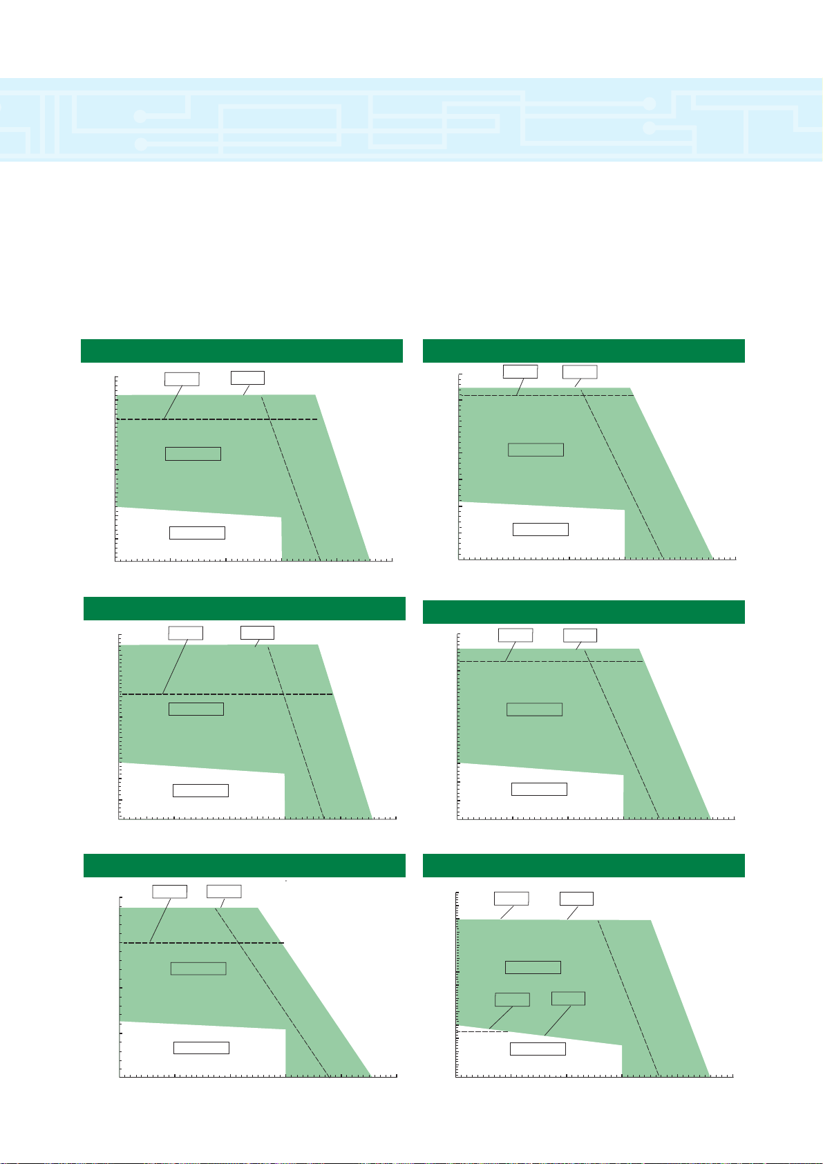
142UMB300 Unimotor
20
15
10
5
0
Torque (Nm)
380 V
480 V
UNI2401
UNI2402
Intermittent Torque
Continuous Torque
0
1000
2000 3000
4000 5000
Speed (rpm)
25
30
35
142UMC300 Unimotor
20
15
10
5
0
Torque (Nm)
380 V
480 V
UNI2402
UNI2403
Intermittent Torque
Continuous Torque
0
1000
2000 3000
4000 5000
Speed (rpm)
25
30
35
40
45
50
142UMD300 Unimotor
20
15
10
5
0
Torque (Nm)
380 V
480 V
Intermittent Torque
UNI2403
UNI3401
Continuous Torque
0
1000
2000 3000
4000 5000
Speed (rpm)
25
30
35
40
45
50
UNI2403
UNI3401
55
60
65
70
115UMD300 Unimotor
10
5
0
Torque (Nm)
380 V
480 V
Intermittent Torque
UNI2402
Continuous Torque
0
1000
2000 3000
4000 5000
Speed (rpm)
15
20
25
UNI2401
30
35
40
115UME300 Unimotor
10
5
0
Torque (Nm)
380 V
480 V
Intermittent Torque
UNI2402
Continuous Torque
0
1000
2000 3000
4000 5000
Speed (rpm)
15
20
35
UNI2401
30
35
40
45
142UMA300 Unimotor
20
15
10
5
0
Torque (Nm)
Intermittent Torque
380 V
480 V
UNI1404
UNI1405
p
Continuous Torque
0
1000
2000 3000
4000 5000
Speed (rpm)
torque speed curves & tables
44
Page 45

142UME300 Unimotor
20
10
0
Torque (Nm)
380 V
480 V
Intermittent Torque
UNI2403
UNI3401
Continuous Torque
0
1000
2000 3000
4000 5000
Speed (rpm)
30
40
50
UNI2403
UNI3401
60
70
80
190UMA300 Unimotor
40
30
20
10
0
Torque (Nm)
380 V
480 V
Intermittent Torque
UNI2403
UNI3401
Continuous Torque
0
1000
2000 3000
4000 5000
Speed (rpm)
50
60
70
UNI2403
UNI3401
190UMB300 Unimotor
0
Torque (Nm)
380 V
480 V
Intermittent Torque
UNI 3403
Continuous Torque
0
1000
2000 3000
4000 5000
Speed (rpm)
50
100
UNI 3402
150
190UMC300 Unimotor
200
150
100
50
0
Torque (Nm)
Intermittent Torque
380 V
480 V
UNI 3405
UNI 4401
Continuous Torque
0
1000
2000 3000
4000 5000
Speed (rpm)
UNI 3405
UNI 4401
190UMD300 Unimotor
200
150
100
50
0
Torque (Nm)
380 V
480 V
Intermittent Torque
Continuous Torque
0
1000
2000 3000
4000 5000
Speed (rpm)
UNI 3405
UNI 4401
UNI 3405
UNI 4401
250
torque speed curves & tables
45
Page 46

46
UNIMOTOR/UNIDRIVE COMBINATION (12 kHz SWITCHING FREQUENCY ONLY)
75UMA300 75UMB300 75UMC300 75UMD300
1.2 2.1 2.8 3.6
3000 3000 3000 3000
1.6 1.6 1.6 1.6
0.8 1.4 1.9 2.5
0.6 1.0 1.5 1.9
UNI1401 N/A UNI1401 UNI1402 UNI1402 UNI1403 UNI1403 UNI1404
0.8 N/A 1.4 1.4 1.9 1.9 2.5 2.5
300 N/A 264 300 258 300 268 300
1.2 N/A 2.1 2.1 2.8 2.8 3.6 3.6
3.5 N/A 5.5 6.2 7.3 8.4 10.0 10.8
Unimotor Model
Cont.Stall Torque (Nm)
Rated Speed (rpm)
Torque Constant (Nm/A
rms
)
Cont. Stall Current (A
rms
)
Rotor inertia (Kgcm
2
)
Unidrive Model (12kHz)
Cont. Current Preset (#0.46)A
Peak Current Preset (#0.06)%
Motor-Drive Combination (Nm)
Stall Torque (Nm)
Peak Torque (Nm)
UNIMOTOR/UNIDRIVE COMBINATION (12 kHz SWITCHING FREQUENCY ONLY)
95UMA300 95UMB300 95UMC300 95UMD300 95UME300
2.3 3.9 5.5 6.9 8.4
3000 3000 3000 3000 3000
1.6 1.6 1.6 1.6 1.6
1.55 2.6 3.67 4.6 5.6
1.4 2.5 3.6 4.7 5.8
UNI1401 UNI1402 UNI1403 UNI1404 UNI1404 UNI1405 UNI1404 UNI1405 UNI1404 UNI1405
1.55 1.55 2.6 2.6 3.67 3.67 4.6 4.6 5.6 5.6
239 300 258 300 270 300 215 300 177 300
2.3 2.3 3.9 3.9 5.5 5.5 6.9 6.9 5.6 5.6
5.55 6.8 10.0 11.7 14.8 16.5 14.8 20.7 14.8 25.1
Unimotor Model
Cont.Stall Torque (Nm)
Rated Speed (rpm)
Torque Constant (Nm/A
rms
)
Cont. Stall Current (A
rms
)
Rotor inertia (Kgcm
2
)
Unidrive Model (12kHz)
Cont. Current Preset (#0.46)A
Peak Current Preset (#0.06)%
Motor-Drive Combination (Nm)
Stall Torque (Nm)
Peak Torque (Nm)
UNIMOTOR Brushless Servo Motors
The time for which the stated overloads can be acheived will vary with the drive/motor combination used. Please consult technical
manual for further details.
UNIMOTOR/UNIDRIVE COMBINATION (12 kHz SWITCHING FREQUENCY ONLY)
115UMA300 115UMB300 115UMC300 115UMD300 115UME300
4.1 6.7 9.5 12.0 14.1
3000 3000 3000 3000 3000
1.6 1.6 1.6 1.6 1.6
2.74 4.47 6.34 8.0 9.4
3.2 5.5 7.8 10.0 12.3
UNI1403 UNI1404 UNI1404 UNI1405 UNI1405 UNI2401 UNI2401 UNI2402 UNI2401 UNI2402
2.74 2.74 4.47 4.47 6.34 6.34 8.0 8.0 9.4 9.4
245 300 221 300 265 300 265 300 226 300
4.1 4.1 6.7 6.7 9.5 9.5 12.0 12.0 14.1 14.1
10.0 12.3 14.8 20.1 25.2 28.5 31.8 36.0 31.8 42.3
Unimotor Model
Cont.Stall Torque (Nm)
Rated Speed (rpm)
Torque Constant (Nm/A
rms
)
Cont. Stall Current (A
rms
)
Rotor inertia (Kgcm
2
)
Unidrive Model (12kHz)
Cont. Current Preset (#0.46)A
Peak Current Preset (#0.06)%
Motor-Drive Combination (Nm)
Stall Torque (Nm)
Peak Torque (Nm)
torque speed curves & tables
Page 47

47
UNIMOTOR/UNIDRIVE COMBINATION (12 kHz SWITCHING FREQUENCY ONLY)
142UMA300 142UMB300 142UMC300 142UMD300 142UME300
6.3 10.8 15.3 19.8 23.4
3000 3000 3000 3000 3000
1.6 1.6 1.6 1.6 1.6
4.2 7.2 10.2 13.2 15.6
7.8 14.1 20.5 26.8 33.1
UNI1404 UNI1405 UNI2401 UNI2402 UNI2402 UNI2403 UNI2403 UNI3401 UNI2403 UNI3401
4.2 4.2 7.2 7.2 10.2 10.2 11.7 13.2 11.7 15.6
236 300 295 300 277 300 338 300 377 300
6.3 6.3 10.8 10.8 15.3 15.3 17.5 19.8 17.5 23.4
14.8 18.9 31.8 32.4 42.3 45.9 59.4 59.4 66.1 70.2
Unimotor Model
Cont.Stall Torque (Nm)
Rated Speed (rpm)
Torque Constant (Nm/A
rms
)
Cont. Stall Current (A
rms
)
Rotor inertia (Kgcm
2
)
Unidrive Model (12kHz)
Cont. Current Preset (#0.46)A
Peak Current Preset (#0.06)%
Motor-Drive Combination (Nm)
Stall Torque (Nm)
Peak Torque (Nm)
UNIMOTOR/UNIDRIVE COMBINATION (9 kHz SWITCHING FREQUENCY ONLY)
190UMA300 190UMB300 190UMC300 190UMD300
21.8 41.1 58.7 73.2
3000 3000 3000 3000
1.6 1.6 1.6 1.6
14.5 27.4 39.1 48.8
44.8 81.6 118.4 155.1
UNI2403 UNI3401 UNI3402 UNI3403 UNI3405 UNI4401 UNI3405 UNI4401
14.2 14.5 27.4 27.4 35 39.1 35 48.8
306 300 255 300 335 300 349 300
21.3 21.8 41.1 41.1 52.5 58.7 52.5 73.2
63.9 63.9 120.0 123.3 176.1 176.1 183 219.6
Unimotor Model
Cont.Stall Torque (Nm)
Rated Speed (rpm)
Torque Constant (Nm/A
rms
)
Cont. Stall Current (A
rms
)
Rotor inertia (Kgcm
2
)
Unidrive Model (12kHz)
Cont. Current Preset (#0.46)A
Peak Current Preset (#0.06)%
Motor-Drive Combination (Nm)
Stall Torque (Nm)
Peak Torque (Nm)
torque speed curves & tables
Page 48

servo sizing software
48
CTSS (CT Sizing Software) is a new servo-sizing
package developed to aid System Design Engineers in
identifying the essential input parameters to correctly
size a servo application. From a system definition and
motion requirement, CTSS performs all calculations
required to produce torque and distance profiles and
gives motor choice optimised on the basis of cost,
length or diameter. The software will specify the
appropriate Unimotor, Unidrive and braking resistor
power, and will generate a parameter list for download
into Unidrive via UniSoft.
A Windows based program, CTSS allows the engineer
to create his application in the Workbench window.
Components are dragged and dropped from the
Toolbox onto the Workbench and are be linked
together using a graphical interface. Component
names and properties can be specified and then saved
as standard or especially components as required.
The Toolbox contains tabbed pages of application
components. Nine main components are provided in
the ‘Standard’ Toolbox page: Gearbox, Lead Screw,
Belt & Pulley, Rack & Pinion, Conveyor, Cylinder Drive
Feed Roll, Coupling and Miscellaneous Inertia. CTSS
allows the user to create any number of Toolbox pages
so that he can group together similar components or
frequently used combinations.
The components can be dragged from the toolbox into
Workbench as required. Each has its own properties
sheet, which describes the component, its
characteristics and illustrates typical applications. The
Component Library provides the option of storage and
retrieval of customised components.
The Results Window displays the motor performance
profile and suggests the best motor for the application,
according to parameters set. Results of the motion
profile may be changed dynamically simply by
dragging and dropping a data point on either the
velocity or distance traces.
Alternatively, the user may simply
modify input parameters directly
of the components in the
application. This window
conforms to a data-centric model
and always displays data relevant
to the userís operations.
CTSS has a Conversion
Tool to assist in changing
between units during data
entry in the Component
Property Pages.
Additionally, the Inertia Tool is
used extensively when specifying
component inertia values. It can
calculate inertia for various forms
ranging from lead to wood.
A major advantage of CTSS is that it allows engineers
to save system designs as files (with a CTS extension).
The user may create a Template design file that is used
as the basis of future designs. The Design Wizard
automates the task of creating a simple application by
performing component placement and connection
based upon selection in the Wizard pages. The
software also allows the creation and storage of notes
about an application in the Design File.
CTSS contains details of the full range of Unimotors
and Unidrives and can be configured in different
languages. To install you will required either Win95 with
12Mb RAM or NT4 with 16Mb RAM.
Page 49

servo sizing software
49
Page 50
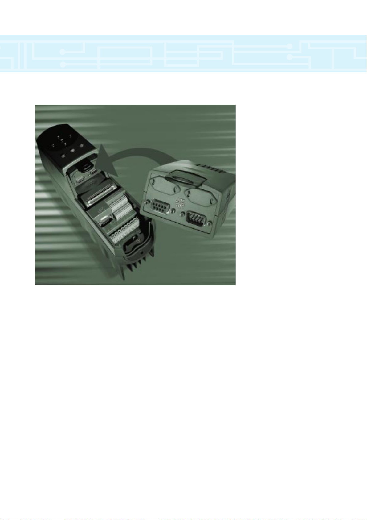
50
● Easy to use, plug in, drives
application module
● Low cost facility to develop
application specific programs
● Advanced microprocessor
technology providing the flexibility to
develop complex applications
● Windows™ based Drive
Programming Language ‘toolkit’
● Bi-directional communications with
full access to drive parameters
● Real-time calculations for complex
time critical applications
● Embedded position controller
● Modbus included as standard
options
UD70 Applications Module
Page 51

51
UD70 Applications Module
Features
Task-based architecture allows easy implementation
of real-time control operations and fixed timebase
calculations. SPEED and ENCODER tasks are
synchronised to the drive’s internal control loops.
Seven separate programmable tasks, listed from highest
to lowest priority:
INITIAL Runs once, immediately after UD70 is reset.
EVENT Triggered by digital input or the
counter/timer unit.
SPEED Synchronised to internal drive speed loop,
runs every 1.38ms or 1.84ms.
ENCODER Synchronised to internal drive encoder loop,
runs every 5.52 or 7.36 ms.
CLOCK Runs every fixed timebase period, selectable
from 5ms to 100ms.
BACKGROUND
Runs when no other tasks are scheduled.
ERROR Runs when an error occurs, allowing a
controlled stop if the error is non-fatal.
● RS485 port - fully configurable. Supports the
following modes:
ANSI protocol as a slave or a master controller,
in 2-wire or 4-wire mode, at data rates from
300 bits/sec to 38400 bits/sec.
MODBUS protocol (ASCII and RTU modes) as a
slave only, at data rates from 300 bits/sec to
19200 bits/sec.
Remote I/O Box high speed protocol. (38400 bits/sec)
● Single character read/write access to the RS485 port
buffers. This allows other protocols to be
implemented using a DPL program.
● External I/O Box can be connected to the RS485
port. Special high speed I/O Box protocol (38400
bits/sec) can be used to read inputs and update
outputs, synchronous with the ENCODER or CLOCK
tasks. For multiple I/O Box connections, ANSI mode
is supported at reduced data rates of 4800 bits/sec
or 9600 bits/sec.
● RS232 port for programming and debugging
programs using the DPL Toolkit. Connection only
requires a simple one-to-one ribbon cable to connect
from a 9-pin PC serial port to the RS232 port.
● High speed read/write access (345 µs or 460 µs) to
speed and torque reference within the drive.
● Internal single axis position controller included, which
can be synchronised to the SPEED or ENCODER
tasks. Absolute positions are stored as 32 bit signed
integers. Full marker pulse and freeze pulse support
is also implemented. Position control, speed control,
digital lock and cam profiling are all supported.
● A 16 bit Counter/Timer unit can be clocked internally
(500kHz or 4MHz) or externally (1MHz max.) This
provides methods for measuring short time intervals,
counting external events, or generating regular fast
interrupts using the EVENT task.
● Two high speed TTL digital inputs and one digital
output. An input can be used to trigger the EVENT
task and perform certain functions when external
events occur.
● 400 internal signed 32 bit registers available for use
with DPL program, of which 200 are non-volatile.
Menu 20 on the Unidrive (50 signed 16 bit
parameters) is also non-volatile.
Specifications
● Intel 960 32 bit RISC processor
● 96K of user program FLASH memory
● 8K of user RAM
● 16MHz clock
● RS232 programming port
● RS485 networking por
● Ambient Temperature: -5ºC to +40ºC
● Storage Temperature: -40ºC to +50ºC
● Weight: 134g
● Maximum Altitude: 4000m
● Humidity: +5% to 95% at 40ºC,
non-condensing
options
Page 52

$VERSION V1.0
$DRIVE UNIDRIVE
$define PITCH% #18.11
$define CIRCUMFERENCE% #18.12
$define CUT_DIST% #18.13
$define MOTOR_ENC_COUNTS% 16384
$define LINE_ENC_COUNTS% #18.14
$define LINE_CIRCUMFERENCE% #18.15
$define GEAR_RATIO% #18.16
$define RE_CALC% #18.31
INITIAL{
; Generate Mod_Sin Array (scaled)
;assign memory space for cam table arrays
DIM sin_array[100]
DIM line%[101]
DIM knife%[101]
;reset program variables
tmr1%=0
sum1=0
sum2=0
index%=0
ang=3.141592654/50
;Create an array with 100 points describing a modified sin
wave
DO
s=sin(ang*index%)
sum1=sum1+s
sin_array[index%]=s1
sum2=sum2+s1
index%=index%+1
LOOP WHILE index%<100
index%=0
;scale the mod_sin array so the total distance moved under
the curve is 1.
Do
sin_array[index%]=sin_array[index%]/s2
index%=index%+1
LOOP WHILE index%<100
;initialise the cam table
result%=CAMINIT(line%,knife%,101,0,0)
;control registers
_Q32%=0
;Reset Control Registers
_Q20%=0
;unidrive set-up parameters
#01.10=1
;Enable Bipolar speed ref.
#01.14=3
;Select Preset Speed reference.
#01.15=1
;Select Preset Speed #1.
#2.02=0
;Disable Speed Ramps
;position loop set-up parameters
_Q20%.1=1
;Enable Q4 as the PID loop reference
_Q20%.6=1
;Enable automatic writing of #91.02
#91.01=3
;Enable the use of #91.2 fast write to Preset
Speed #1.
#91.05=1500
;Set the maximum resolution speed in rpm of
#91.02
}
BACKGROUND{
top:
;calculate adjustments required for the rotary knife to cut in
the required place
line_scale%=LINE_ENC_COUNTS%/LINE_CIRCUMFERENCE
%
knife_scale%=MOTOR_ENC_COUNTS%*GEAR_RATIO%/CIR
CUMFERENCE%
catch_up_length%=(CIRCUMFERENCE%-PITCH%CUT_DIST%)*knife_scale%
pitch_increment_line%=(PITCH%CUT_DIST%)*line_scale%/100
pitch_increment_knife%=(PITCH%CUT_DIST%)*knife_scale%/100
;calculate the Cam table points to describe the required
motion
IF RE_CALC%=1 THEN
index%=0
Do
line%[index%]=pitch_increment_line%
knife%[index%]=INT(sin_array[index%]*catch_up_length%) +
pitch_increment_knife%
index%=index%+1
LOOP WHILE index%<100
line%[100]=CUT_DIST%
knife%[100]=CUT_DIST%
RE_CALC%=0
ENDIF
;Set the speed of the virtual axis for test purposes
v_master%=#18.20
goto top: // main background loop
}
SPEED{
;Increment the c/ required for the virtual master speed.
_Q1%=_Q1%+v_master%
}
options
Rotary Knife
(Example of DPL Code)
52
Page 53

Drive Communications
UD71 Serial Communications Module
● RS232 communications for easy commissioning and
drive programming
● RS485 communications for industrial process control
Distributed Applications
● UD70 Modbus Module (19.2 Kbps)
● UD73 Profibus DP Module (1.5 Mbps)
● UD74 Interbus S Module (0.5 Mbps)
● UD76 Modbus+ Module (1 Mbps)
● UD77 DeviceNet (0.5 Mbps)
● UD75 CTNet Module (5 Mbps)
● Peer to peer communications
● Distributed control
● Simplifies high performance
industrial applications
Easy Applications
UD78 High Performance Servo Module
● >16 bit analogue input for precise position control
● Accurate tracking of small input signal changes with
<150µV deadband
● 24V back-up tracks encoder position when
mains loss is experienced
● RS485 communications
Feedback Device
UD50 Extended I/O
● Low cost external control
● 2 N/0 relays
● 3 Digital inputs
● 3 Digital I/0
● 2 Analogue inputs
● 1 Analogue output
UD51 Second Encoder
● Master/Slave capability for multiple drive control
(Digital Lock)
● Quadrature or frequency and direction reference
● Freeze input
● Simulated encoder output
UD52 Sin/Cos Encoder
● High precision positioning
● 500,000 ppr
● Single or multi-turn
● Absolute position tracked
● Freeze input
UD53 Resolver Feedback
● Easy expansion of drive for use in rugged and
demanding environments
● Simulated encoder output
Drive Set Up
UD55 Cloning Module
● Easy set-up of multiple drives
● Simplifies the transfer of parameters between Drives
● Stores 8 full parameter sets
options
53
Page 54

Pick and Place Gantry Control
Objective: Utilise standard products with easy
programming for point-to-point position control
Solution: Unidrive with MC204 controller
Operation: MC204 moves all three axes from 3-D position
to 3-D position co-ordinates quickly and
accutately.
Results: Easy system set up with rapid and accurate
positioning.
High Speed Label Printing
Objective: Higher throughout, decreased changeover
time, better accuracy than mechanical system
Solution: Unidrive with UD70 digital lock
Operation:The UD70 performs a complex cam type
profile to insure placing arm and product are
always at the same speed.
UD70 compensates for small product to
product registration shifts by using a product
sensor on the master axis.
Results: Increased accuracy because placement
follows product regardless of conveyor speed.
Constant Web Speed Unwind Control
with Tension Input
Objective: Precise and constant web speed and position
control.
Solution: Unidrive with UD70 winder control.
Operation: UD70 controls the web speed and position
based on encoder signal input. As the
diameter of the take up roll increases, the
Unidrive slows the speed of the Unimotor.
Results: Precise speed regulation and the exact amount
of material is wound onto the take up roll.
typical applications
MC Series
Unidrives
Unimotor
Unimotor
Unimotor
scale
flow
6
7
5
4
3
21
9
10
Encoder
Unidrive UD70
Digital look
Unidrive UD70
Digital look
Follower
Axis
Master
Axis
Flow
Unidrive
with UD70
CTIU
Operator Interface
Unimotor
Encoder
54
Page 55

Constant Controller Maintains Constant Gap
Objective: Provide desired “Tail to Head” spacing.
Regardless of product length.
Solution: Unidrive with UD70 applications module.
Operation: Photocells trigger the PCM-19 to monitor
encoder input for product position, length and
height. The UD70 preforms all the
calculations required to deliver the product
to the merge conveyor at the user defined
parameters.
Results: Easy configuration and control of product
tail to head or head to head spacing onto a
merge conveyor.
Auger Filler for Dry Material
Objective: Eliminate problems with clutch-brakes.
Solution: Unidrive and UD70 count position control.
Operation:Unidrive indexes exact revolutions for specific
volume. Operator only needs to enter user
units into CTIU operator interface.
Results: Increased accuracy eliminates overfilling to
meet minimum weight requirements.
Waste is eliminated.
XYZ Axes Application
Objective: Increase accuracy and performance of multi-
axis systems.
Solution: MC204 and Unidrive
Operation:Unidrive read analog signals from multi-axis
controller to determine position and speed.
Results: Fast and accurate positioning of all axis.
typical applications
Unidrive
with UD70
Product
Measuring
Photoeye
Separation
Conveyor
Measuring
Conveyor
Feed Control
Conveyor
Merge Conveyer
Sync Encoder
Unimotor
Unimotor
Unimotor
CTIU
Operator interface
Unimotor
Unimotor
Unimotor
Unidrive
MC Series
Z
Z
X
X
Y
Y
55
Page 56

Flying Cut Off - Inline
Objective: Provide an easy method for an operator to
enter product cut lengths
Solution: Unidrive with UD70 motion profiler and CTIU
operator interface.
Operation:When the correct product length passes, the
cut bar is accelerated to match the speed of
the product. When speed is matched, an
output is activated sending the cutter head
down. The operator is able to set the length
using the CTIU operator interface.
Results: Easy data entry with fast and accurate cut cycles.
Rotary Cut Off
Objective: Cut material to user specified length and
maintain cut on the registration marks.
Solution: Unidrive with UD70 natural profiler.
Operation: the UD70 monitors the encoder position and
product registration sensor to insure that the
product is cut in the correct position. The
UD70 has the capability to learn the exact new
length of the product even if the operator
enters a length close to the correct length. Any
changes to the drive parameters can be made
on the fly.
Results: Synchronised system provides fast and
accurate cut lengths exactly placed on
registration marks.
Positioning with a Unidrive
Objective: Increase accuracy and performance and
minimize cost.
Solution: Unidrive with UD70 positioner
Operation:Proximity switches are placed at the desired
drill position. The Unidrive is configured to stop
at an exact and consistant deceleration rate.
Results: Fast and accurate positioning of workpiece
with system cost minimized.
Output 21on
Output 22on
Output s off
Index 1
2,000 inches
Index 3
2,000 inches
Index 4
return to 0 position
Velocity
(+)
Index 2
10,000 inches
(-)
Wait for 40 more
inches to pass
Motion Program
CTIU
Operator Interface
SCS-X
Encoder
Unidrive
with UD70
Unimotor
Motion
Motion
typical applications
56
Unidrive
with
UD70
Registration
Sensor
Unimotor
Encoder
Rotary
Knife
Flow
Leadscrew Pitch: 2 TPI
Repaetability: +/-0003
inches
Speed: 1750 IPM
SELECTED
PROGRAMMED
SPEED
STOP CONTACT
OPENS
ACCEL & DECEL
RAMPS
STOP CONTACT
CLOSES
PROGRAMMED MOTOR
STOP POSITION
Load and Upload
Area
Workpiece
Drill
Tap
Unidrive
Unimotor
eg Profibus,
Devicenet
Page 57

driving the world...
© Control Techniques 1999. The information contained in this brochure is for guidance only and does not form part of any contract. The accuracy cannot be guaranteed as Control Techniques have an
ongoing process of development and reserve the right to change the specification of their products without notice.
0175-0306 03/99
•
Drive & Application Centres
•
Distributors
AUSTRALIA
Melbourne Application Centre
A.C.N. 003 815 281
Tel: 61 973 8177
Fax: 61 9729 3200
After Hours: 61 2 9963 5271
Sydney Drive Centre
A.C.N. 003 815 281
Tel: 61 2 9838 7222
Fax: 61 2 9838 7764
After Hours: 61 2 9963 5271
AUSTRIA
Linz Drive Centre
Tel: 43 7229 789480
Fax: 43 7229 7894810
After Hours: 43 7215 3502
BELGIUM
Brussels Drive Centre
Tel: 32 2725 2721
Fax: 32 2725 4940
CANADA
Toronto Drive Centre
Tel: 1 905 475 4699
Fax: 1 905 475 4694
CHINA
Shanghai Drive Centre
Tel: 86 21 64085747
Fax: 86 21 64083282
CZECH REPUBLIC
Brno Drive Centre
Tel: 420 541 192111
Fax: 420 541 192115
After Hours: 420 603 841983
DENMARK
Århus Application Centre
Tel: 45 8625 5755
Fax: 45 8625 1755
After Hours: 45 4369 6100
Copenhagen Drive Centre
Tel: 45 4369 6100
Fax: 45 4369 6101
After Hours: 45 4369 5100
FINLAND
Helsinki Drive Centre
Tel: 358 985 2661
Fax: 358 985 26823
After Hours: 358 500 423271
FRANCE
Leroy Somer
Angouleme Drive Centre
Tel: 33 5 4564 5454
Fax: 33 5 4564 5400
GERMANY
Bonn Drive Centre
Tel: 49 2242 8770
Fax: 49 2242 877277
After Hours: 49 1714 964777
Chemnitz Drive Centre
Tel: 49 3722 52030
Fax: 49 3722 520330
After Hours: 49 1714 964777
Darmstadt Drive Centre
Tel: 49 6251 17700
Fax: 49 6251 177098
After Hours: 49 1714 964777
Stuttgart Drive Centre
Tel: 49 7156 95560
Fax: 49 7156 955698
After Hours: 49 1714 964777
HOLLAND
Rotterdam Drive Centre
Tel: 31 1844 20555
Fax: 31 1844 20721
After Hours: 31 1844 20555
HONG KONG
Hong Kong Application Centre
Tel: 852 2979 5271
Fax: 852 2979 5220
HUNGARY
Budapest Drive Centre
Tel: 361 431 1160
Fax: 361 260 5483
INDIA
Bombay Application Centre
Tel: 91 20 751201/751202/750930
Fax: 91 20 750105
After Hours: 91 44 4984868
Calcutta Application Centre
Tel: 91 33 357 5302/357 5306
Fax: 91 33 357 3435
After Hours: 91 44496 1083
Madras Drive Centre
Tel: 91 44
4961123/4961130/4961083
Fax: 91 44 4961602
New Delhi Application Centre
Tel: 91 11 576 4782
Fax: 91 11 576 4782
After Hours: 91 44 4984868
INDONESIA
Jakarta Drive Centre
Tel: 62 21 4525146
Fax: 62 21 4525142
After Hours: 62 81 687 0443
Surabaya Application Centre
Tel: 62 31 5682775/5623565
Fax: 62 31 5622402
After Hours: 62 81 687 0443
IRELAND
Dublin Drive Centre
Tel: 353 45 433044
Fax: 353 45 433622
ITALY
Milan Drive Centre
Tel: 39 02575 751
Fax: 39 02575 12858
After Hours: 39 02575 751
Vicenza Drive Centre
Tel: 39 0444 396200
Fax: 39 0444 341317
KOREA
Seoul Application Centre
Tel: 82 2 3445 6183/6184/6185
Fax: 82 2 3445 6181
After Hours: 82 23 445 6183
/82 11 732 9676
MALAYSIA
Kuala Lumpur Drive Centre
Tel: 60 3734 9776
Fax: 60 3733 9592
After Hours: 60 12 333 8355
NORWAY
Oslo Application Centre
Tel: 47 32 235100
Fax: 47 32 235101
After Hours: 47 92 22 3292
REPUBLIC OF SOUTH AFRICA
Johannesburg Drive Centre
Tel: 27 11 462 1740
Fax: 27 11 462 1941
After Hours: 27 11 462 1740
RUSSIA
Moscow Application Centre
Tel: 7 095 232-9472
Fax: 7 095 956-4862
After Hours: 91 44496 1083
SINGAPORE
Singapore Drive Centre
Tel: 65 271 6377
Fax: 65 272 1302
SPAIN
Barcelona Drive Centre
Tel: 34 93 680 1661
Fax: 34 93 680 0903
/34 93 680 0763
/34 93 680 2823
After Hours: 34 610 554540
Bilbao Application Centre
Tel: 34 94 620 3646
Fax: 34 94 681 1406
Valencia Drive Centre
Tel: 34 96 154 2900
Fax: 34 96 153 2906
SWEDEN
Stockholm Application Centre
Tel: 46 8 554 24100
Fax: 46 8 554 24120
SWITZERLAND
Lausanne Application Centre
Tel: 41 21 634 0408
Fax: 41 21 635 8596
After Hours: 41 79 357 8683
Zurich Drive Centre
Tel: 41 56 201 4242
Fax: 41 56 201 4243
After Hours: 41 79 357 8683
TAIWAN
Taipei Application Centre
Tel: 886 22325 9555
Fax: 886 22705 9131
THAILAND
Bangkok Drive Centre
Tel: 66 2580 7644
Fax: 66 2591 4559
A/Hours Sales: 66 1443 4095-7
A/Hours Service: 66 1443 4098
TURKEY
Istanbul Drive Centre
Tel: 90 216 4182420
Fax: 90 216 4182423
After Hours: 90 216 418 2420
UNITED KINGDOM
Telford Drive Centre
Tel: 44 1952 213700
Fax: 44 1952 213701
After Hours: 44 1952 213700
Leeds Drive Centre
Tel: 44 113 2423400
Fax: 44 113 2423892
After Hours: 44 113 2423400
Luton Drive Centre
Tel: 44 1582 567700
Fax: 44 1582 567703
After Hours: 44 1582 567700
Warrington Application Centre
Tel: 44 1925 413537
Fax: 44 1925 242808
After Hours: 44 113 242 3400
USA
Charlotte Application Centre
Tel: 1 704 393 3366
Fax: 1 704 393 0900
After Hours: 1716 692 2442
Chicago Drive Centre
Tel: 1 630 893 5249
Fax: 1 630 893 4156
Cleveland Drive Centre
Tel: 1 440 717 0123
Fax: 1 440 717 0133
Minneapolis Application Centre
Tel: 612 474 1116
Fax: 612 474 8711
Dallas Application Centre
Tel: 1 972 783 1831
Fax: 1 972 783 9978
After Hours: 1800 759 0664
Providence Drive Centre
Tel: 1 401 333 3331
Fax: 1 401 333 6330
After Hours: 1401 333 0080
VIETNAM
Ho Chi Minh Application Centre
Tel: 84 8 842 5157
/84 8 849 1980
Fax: 84 8 8425157
Control Techniques
Drive & Application Centres
............
............
............
 Loading...