

Page 1

User Guide
UD78UD78
Servo
large option module
for Unidrive
Part Number: 0460 - 0086
Issue Number: 2
Page 2

General Information
The manufacturer accepts no liability for any consequences resulting from
inappropriate, negligent or incorrect installation or adjustment of the
operating parameters of the equipment or from mismatching the Drive
with the motor.
This option module is intended for use only with Control Techniques
Unidrive products. Any other use invalidates the warranty and may cause a
safety hazard.
The contents of this Guide are believed to be correct at the time of
printing. In the interests of a commitment to a policy of continuous
development and improvement, the manufacturer reserves the right to
change the specification of the product or its performance, or the
contents of this Guide, without notice.
All rights reserved. No part of this Guide may be reproduced or
transmitted in any form or by any means, electrical or mechanical including
photocopying, recording or by any information storage or retrieval system,
without permission in writing from the publisher.
Use within the European Union, etc
The following information applies where the end use of the Drive is within
the European Union, the European Economic Area, or other regions which
have implemented Directives of the European Council or equivalent
measures.
The Drive, together with its associated option modules, complies with the
Low Voltage Directive 73/23/EEC.
The installer is responsible for ensuring that the equipment into which the
Drive is incorporated complies with all relevant Directives.
The complete equipment must comply with the EMC Directive 89/336/EEC.
If the Drive is incorporated into a machine, the manufacturer is responsible
for ensuring that the machine complies with the Machinery Directive
89/392/EEC. In particular, the electrical equipment should generally
comply with European Harmonised standard EN60204-1.
Copyright © January 2002 Control Techniques Drives Ltd
Issue Code: 78nu2
Page 3

Contents
Chapter
1 Introduction 1
1.1 Main features of the UD78 1
2 Safety Information 3
3 Installing the UD78 6
4 Making Connections 8
4.1 Locations of the connectors 8
4.2 SK1
4.3 SK2
4.4 PL1
Precision analog input
Functions of the terminals............................................................................................9
Specification.......................................................................................................................10
Back-up DC supply input
Functions of the terminals............................................................................................11
Specification.........................................................................................................................11
Operation.............................................................................................................................12
Serial communications
Functions of the terminals...........................................................................................13
Specification........................................................................................................................13
Serial communications modes.................................................................................14
Ground connection........................................................................................................16
Routing the serial communications cable...........................................................17
Terminating the cable....................................................................................................17
Operation..............................................................................................................................17
connector 9
connector 11
connector 13
5 Related Parameters 18
5.1 Introduction 18
5.2
5.3
5.4
UD78 User Guide
Issue code: 78nu2
Precision analog input
Back-up DC supply
parameter 22
Serial communications
parameters 19
parameters 21
Page 4

Appendix
A Serial Comms. ANSI Message Formats A-1
A.1 Fundamentals of data transmission A-1
A.2 Reading a parameter value A-4
A.3 Re-reading a parameter value A-5
A.4 Writing a parameter value A-5
A.5 Re-writing a parameter value A-6
A.6 Calculating the block checksum (BCC) A-6
B Setting up the Drive using UniSoft B-1
UD78 User Guide
Issue code: 78nu2
Page 5

1 Introduction
1.1 Main features of the UD78
Note
The UD78 can be used only with Drives equipped with
version 3 (or later) software. (Parameter 0.50 indicates
the software version.)
Main
functions
Back-up
DC
supply
The UD78 large option module is an interface module for installation in a
Unidrive and has the following functions:
• Precision analog input
• EIA RS485, 4-wire or 2-wire, serial communications interface (fully
opto-isolated)
• Back-up +24V
Drive (and the UD78) operating when the AC supply to the Drive is
disconnected.
DC supply input for keeping the control circuits of the
Serial communications
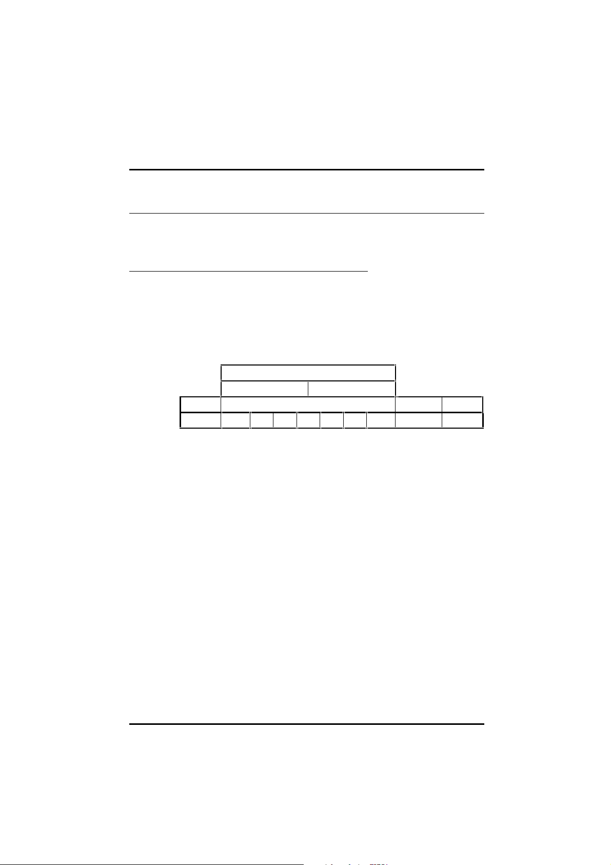
Figure 1 The functions of the UD78 connectors
UD78 User Guide
Issue code: 78nu2
Precision analog input
1
Page 6

Precision
analog input
Serial
comms.
interface
Installation
The precision analog input replaces terminals 5 and 6 Analog input 1 in the
Drive. Terminals 5 and 6 can then not be used for any purpo se. The
parameters associated with Analog input 1 now relate to the pr ecision
input.
The serial communications interface allows the following:
• The Drive to be controlled and monitored remotely by a
system controller
• The Drive to control or monitor another Drive
The UD78 must be fitted in the large option module bay of the Unidrive.
Precision analog input and serial communications connections are made by
9-way D-type connectors. The external Back-up
made by a pluggable 5-way screw-terminal block.
DC supply connections are
UD78 User Guide
2
Issue code: 78nu2
Page 7

2 Safety Information
2.1
Warnings, Cautions and Notes
A Warning contains information which is essential for avoiding a safety
hazard.
A Caution contains information which is necessary for avoiding a risk of
damage to the product or other equipment.
A Note contains information which helps to ensure correct operation of the
product.
2.2 Electrical safety – general warning
The voltages used in the Drive can cause severe electric sho ck and/or burns,
and could be lethal. Extreme care is necessary at all times when working
with or adjacent to the Drive.
Specific warnings are given at the relevant places in this User Guide.
The installation must comply with all relevant safety legislation in the
country of use.
The Drive contains capacitors that remain charged to a poten tially lethal
voltage after the
energized, the AC supply must be isolated at least ten minutes before work
may continue.
AC supply has been disconnected. If the Drive has been
2.3 System design
The Drive is intended as a component for professional incorporation into
complete equipment or systems. If installed in correctly the Dr ive may
present a safety hazard. The Drive uses high voltages and currents, carries
a high level of stored electrical energy, and is used to control m echanical
equipment which can cause injury.
Close attention is required to the electrical installation and the systemdesign to avoid hazards either in normal operation or in the event of
equipment malfunction. System-design, installation, commissioning and
maintenance must be carried out by personnel who have the necessary
training and experience. They must read this safety information and this
User Guide carefully.
To ensure mechanical safety, ad ditional safety devic es such as
electro-mechanical interlocks m ay be required. The Dr ive must not be u sed
in a safety-critical application without additional high-integrity protection
against hazards arising from a malfunction.
UD78 User Guide
Issue code: 78nu2
3
Page 8

2.4 Environmental limits
Instructions in the Unidrive Installation Guide regarding transport, storage,
installation and use of Drives must be complied with, including the specified
environmental limits. Drives must no t be subjected to exc essive physical
force.
2.5 Compliance with regulations
The installer is responsible for complying with all relevant regulations, such
as national wiring regulations, accident prevention regulations and
electromagnetic compatibility (EMC) regulations. Particular attention must
be given to the cross-sectional areas of conductors, the selection of fuses or
other protection, and protective earth (ground) connections.
The Unidrive Installation Guide contains instructions for achieving compliance
with specific EMC standards.
Within the European Union, all machinery in which this product is used must
comply with the following directives:
89/392/EEC: Safety of Machinery
89/336/EEC: Electromagnetic Compatibility
2.6 Safety of personnel
The STOP function of the Drive does not remove dangerous voltages from
the output of the Drive or from any external option unit.
The Stop and Start controls or electrical inputs of the Drive should not be
relied upon to ensure safety of personnel. If a safety hazard could exist
from unexpected starting of the Drive, an interlo ck that electric ally isolates
the Drive from the
inadvertently started.
Careful consideration must be given to the functions of the Drive which
might result in a hazard, either through their intended functions (eg.
Auto-start) or through incorrect operation due to a fault or trip (eg.
stop/start, forward/reverse, maximum speed).
Under certain conditions, the Drive can suddenly discontinue control of the
motor. If the load on the motor cou ld cause the moto r speed to be
increased (eg. hoists and cranes), a separate method of braking and
stopping the motor should be used (eg. a mechanical brake).
Before connecting the
understand the operating controls and their operation. If in doubt, do not
adjust the Drive. Damage may occur, or lives put at risk. Carefully follow
the instructions in this User Guide.
Before making adjustments to the Drive, ensure all personnel in the area are
warned. Make notes of all adjustments that are made.
AC supply should be installed to prevent the motor being
AC supply to the Drive, it is important that you
UD78 User Guide
4
Issue code: 78nu2
Page 9

2.7 Risk analysis
In any application where a malfunction of the Drive could lead to damage,
loss of life or injury, a risk analysis must be carried out, and where necessary,
further measures taken to reduce the risk. This would normally be an
appropriate form of independent safety back-up system using simple
electro-mechanical components.
2.8 Signal connections
The control circuits are isolated from the po wer circuits in the Drive by basic
insulation only, as specified in IEC664–1. The installer must ensure that the
external control circuits are insulated from human contact by at least one
layer of insulation rated for use at the AC supply voltage.
If the control circuits are to be connected to other circuits classified as
Safety Extra Low Voltage (SELV) (eg. to a personal computer), an additional
isolating barrier must be included in order to maintain the SELV
classification.
2.9 Adjusting parameters
Some parameters have a profound effect on the operation of the Drive.
They must not be altered without careful consideration of the impact on
the controlled system. Measures must be taken to prevent un wanted
changes due to error or tampering.
UD78 User Guide
Issue code: 78nu2
5
Page 10

3 Installing the UD78
Before using the following procedure, refer to the
Warnings at the beginning of Chapter 2 Installing the Drive in
Warning
the Unidrive Installation Guide.
1 Before installing the UD78 in the Unidrive, ensure the AC supply has
been disconnected from the Drive for at least 10 minutes.
2 Check that the exterior of the UD78 is not damaged, and that the
multi-way connector is free from dirt and debris. Do not install a
damaged or dirty UD78 in the Drive.
3 Remove the terminal cover from the Drive (for removal instructions,
see Installing the Drive and RFI filter in Chapter 2 of the Unidrive
Installation Guide).
4 Push the UD78 into the cavity immediately behind the keypad and
display until the UD78 locks in place.
5 Re-fit the terminal cover to the Drive.
6 Connect the AC supply to the Drive.
7 Set parameter .00 at 149 to unlock security.
8 Check that parameter 7.31 is set at 1 to indicate that the module is
fitted.
9 If the check in step 8 fails, perform the following:
• Remove the
• Wait at least 10 minutes.
• Remove the terminal cover.
• Check that the UD78 is fully inserted.
• Replace the terminal cover.
• Re-apply the
• Check again that parameter 7.31 is set at
AC supply from the Drive.
AC supply.
1.
UD78 User Guide
6
Issue code: 78nu2
Page 11
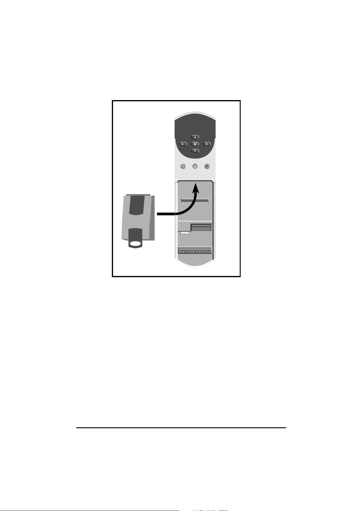
Figure 2 Installing the UD78 in the Unidrive
Do not remove the UD78 from the Drive when either the
DC back-up supply is applied to the Drive. If the UD78 is removed when the
Drive is powered-up, the Drive will trip; the display will indicate ANI.diS.
If the UD78 is deliberately removed, it may be necessary to re-adjust the
parameters related to analog input 1, since they will now relate to termin als
5 and 6.
UD78 User Guide
Issue code: 78nu2
AC supply or a
7
Page 12
4 Making Connections
The control circuits are isolated from the power circuits in
the Drive by basic insulation only, as specified in IEC664–1.
The installer must ensure that the external control circuits
Warning
4.1 Locations of the connectors
are insulated from human contact by at least one layer of
insulation rated for use at the
If the control circuits are to be connected to other circuits
classified as Safety Extra Low Voltage (SELV) (eg. to a
personal computer), an additional isolating barrier must be
included in order to maintain the SELV classification.
AC supply voltage.
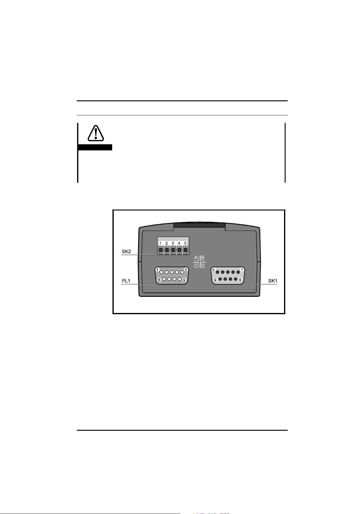
Figure 3 Locations of the connectors on the UD78
8
UD78 User Guide
Issue code: 78nu2
Page 13
4.2 SK1
Precision analog input connector
−Vout
+Vout
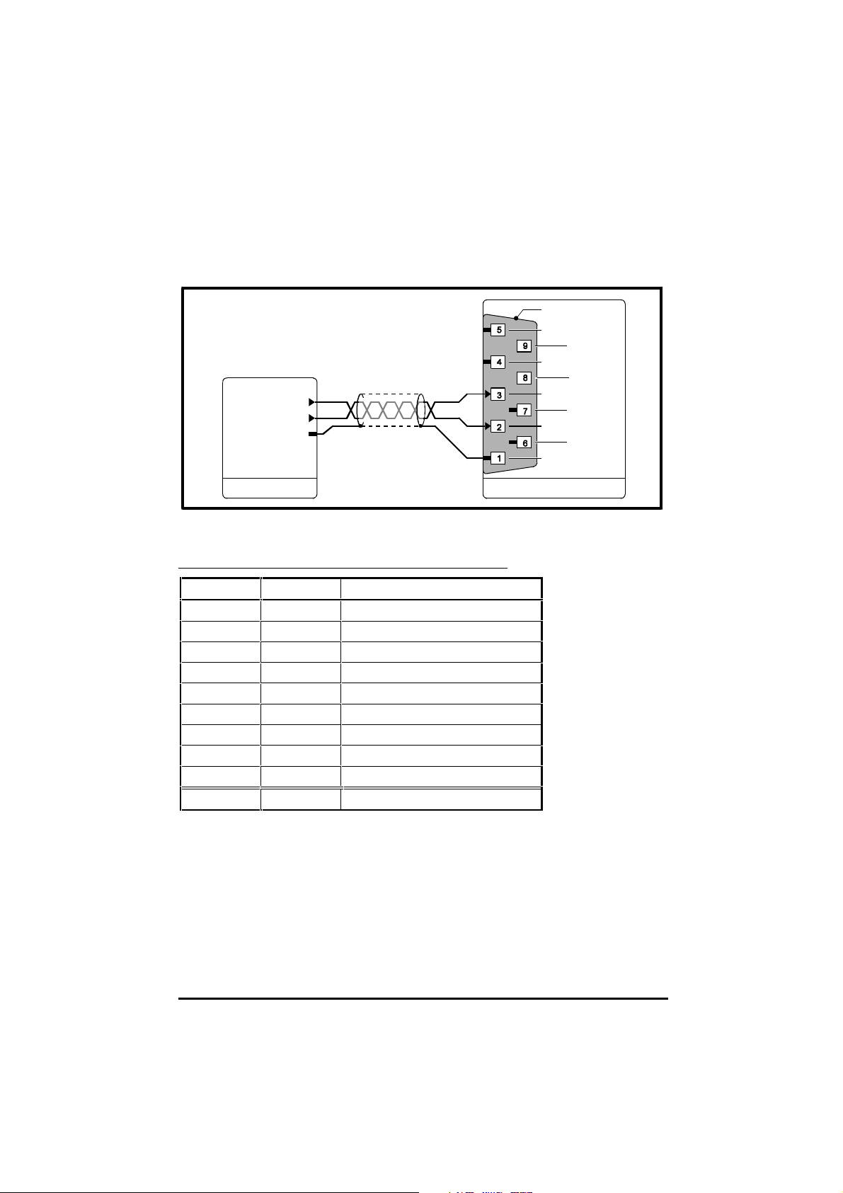
SK1 [UD78]System controller
Figure 4 Connections to the precision analog input
Functions of the terminals
Terminal Name Function
10VD0V
2 +Vin Reference input +
3 –Vin Reference input –
40VD0V
5 NC Not connected
60VD0V
70VD0V
80VD0V
9 NC Not connected
Shell 0VD 0V
0VD
NC
NC
0VD
0VD
−Vin
0VD
+Vin
0VD
0VD
UD78 User Guide
Issue code: 78nu2
9
Page 14

Specification
Input type Differential
Mode Bipolar voltage
Full-scale differential input voltage ±9.8V ±1% (see parameter 7.25)
Absolute maximum differential input voltage ±30V
Absolute maximum input voltage ±50V relative to 0VD
Common mode rejection ratio 95dB
Input resistance 20kΩ
Full-scale asymmetry ±0.1% maximum
Offset error <150µV
Dead-band at zero input <150µV
Zero-crossing error <150µV
Linearity error ±0.1% of full scale
Input-filter time-constant 10µs
Resolution Open-loop: 12-bit plus sign
Closed-loop: ∞ (pulses are accumulated)
Sample period (See below)
Operating mode Destination parameter
for the analog input
Closed-loop 1.36 Analog reference 1 3, 6, 12 345µs
1.37 Analog reference 2 4, 5, 9 460µs
3.19 Hard speed reference
4.08 Torque reference
Open-loop 1.36 Analog reference 1 3, 6, 12 1.38ms
1.37 Analog reference 2 4, 5, 9 1.84ms
4.08 Torque reference
All other parameters 3, 6, 12 5.5ms
PWM switching
frequency (kHz)
4, 5, 9 7.4ms
Sample period
UD78 User Guide
10
Issue code: 78nu2
Page 15

4.3 SK2
Back-up DC supply input connector
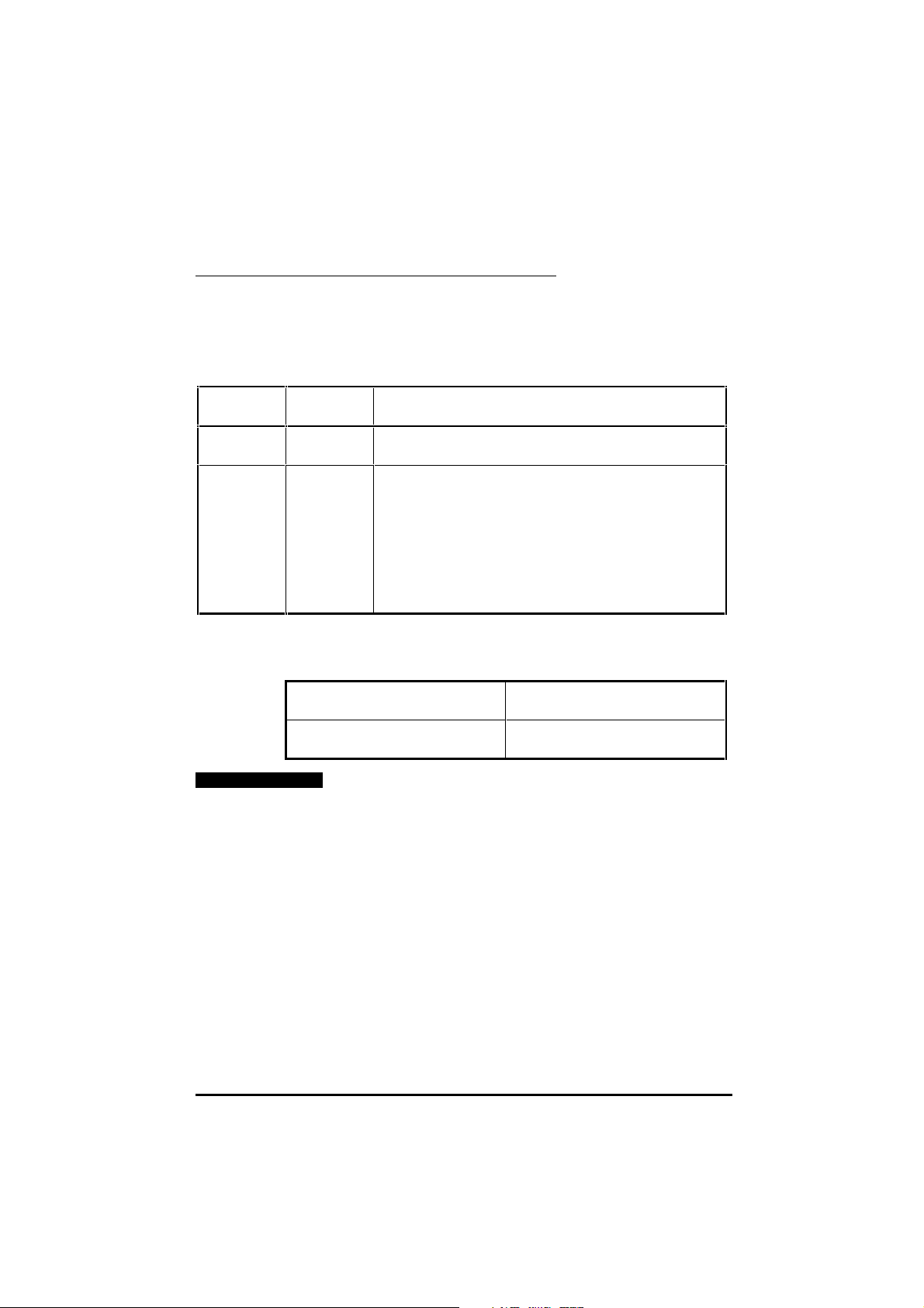
Functions of the terminals
Terminal Name Function
10VD0V
2 +DC +24 Volts supply input
3 NC Not connected
40VD0V
5 +DC +24 Volts supply input
Terminals 2 and 5 are internally connected to allow chain connection for up
to three Drives. When four or more Drives are connected, a star wiring
configuration should be used.
Specification
Required supply voltage (including ripple) 22.8V ~ 26.4V
Maximum ripple at 100Hz 1V RMS
Absolute maximum voltage +50V
Absolute maximum reverse voltage –30V
Continuous current when the AC supply is
disconnected from the Drive
Continuous current when the AC supply is
connected to the Drive
Temperature limits (See below)
<1A
20mA
Drive powered only by the back-up DC supply Up to 30°C
(86°F)
Up to 40°C
(104°F)
Drive powered by the AC supply
UD78 User Guide
Issue code: 78nu2
Up to 40°C
(104°F)
Up to 50°C
(122°F)
The Drive can be powered
indefinitely
The Drive can be powered for
15 minutes maximum
The Drive can be powered
indefinitely
Refer to the Unidrive Installation
Guide
11
Page 16
Operation
For automatic operation of the back-up DC supply, this supply should be
connected continuously.
The following table shows the results of a combination of supply conditions.
AC supply is considered to be removed when it is below
A 400V
approximately 230V RMS.
AC supply Back-up
DC supply
Present Present or
absent
Absent Present If the AC supply is present, then removed, parameters that are saved
Resulting effect
Control circuits and power stages operate
(Drive fully operational, including the precision analog input)
at power-down are saved
Only the control circuits operate
The Drive cannot power a motor
The Drive displays LOPS
The Drive can be programmed either manually or via
serial communications, but parameter values cannot be saved
Model sizes 1 and 2: Heatsink fan operates
Model sizes 3 and 4: Heatsink fans do not operate
Power-up delays
The following delays occur:
AC supply disconnected
DC supply being connected
Back-up
Back-up DC supply already connected
AC supply being connected
5 second delay for Drive display and serial
communications to become active
5 second delay before the Drive can be
enabled
Note
Stator resistance test (open-loop only)
If parameter 5.14 (0.07) is set at Ur_I for the Drive to perform a stator
resistance test at power-up, and the AC supply is disconnected, the Drive
will trip if the Back-up DC supply is connected. The Drive will display trip
code rS, indicating failure to perform the stator resistance test.
To prevent this occurring, set parameter 5.14 ( 0.07) at one of the
following, and refer to Voltage boost in Chapter 4 Menu 0 parameters in the
Unidrive User Guide:
Ur_S, Ur, Fd
12
UD78 User Guide
Issue code: 78nu2
Page 17

4.4 PL1
Serial communications connector
Functions of the terminals
Terminal Name Function
1 0VSC 0V
2 TX\ Transmit output (inverted)
3 RX\ Receive input (inverted)
4TXTERM TX termination-resistor
connection
5RXTERM RX termination-resistor
connection
6 TX Transmit output
7 RX Receive input
8TX\TERM TX\ termination-resistor
connection
9RX\TERM RX\ termination-resistor
connection
Shell 0VSC 0V
Specification
RX (input) 2 unit-loads (EIA RS485)
TX (output) 2 unit-loads (EIA RS485)
2-wire (Transceiver mode) 4 unit-loads (EIA RS485)
Termination resistance 120Ω ±5% (no series capacitor)
In accordance with the EIA RS485 specification, the total load on a line must
not exceed 32 unit-loads. Each transmitter an d receiver of the UD7 8 loads
the line by two unit-loads (in two-wire mode, each UD78 loads the line by
four unit-loads). This allows the following to be operated:
• 15 units in 4-wire mode
• 7 units in 2-wire mode
When line repeaters are used, up to 81 Control Techniques devices can be
operated. In this case the devices must be arranged in up to nine groups of
nine. A particular group or groups can be given commands without
affecting other devices or groups of devices.
UD78 User Guide
Issue code: 78nu2
13
Page 18
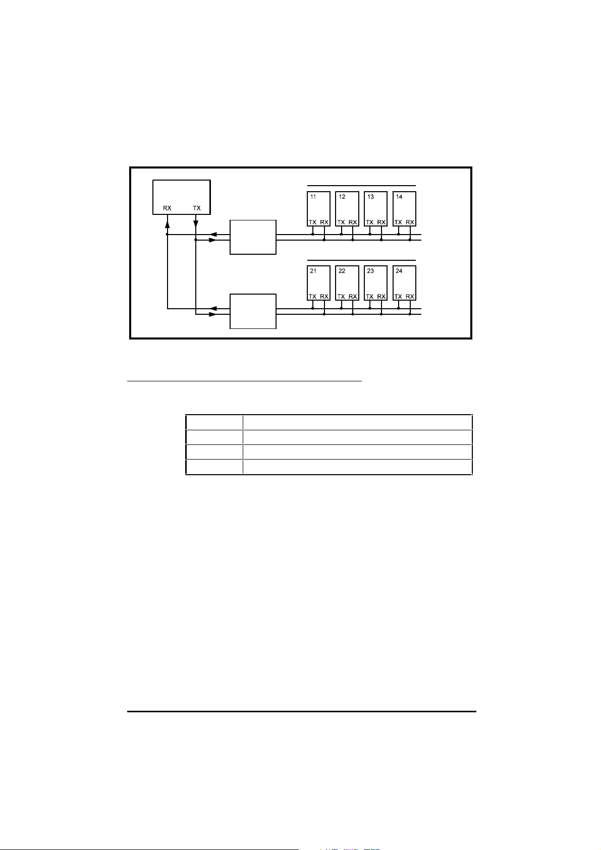
System
controller
Line
repeater
Line
repeater
Group 1
Group 2
Figure 5 RS485 multi-drop link having two groups of four units
Serial communications modes
The serial communications interface can be set up for operation in the
following modes:
2-wire ANSI Half-duplex communications (transceiver mode)
4-wire ANSI Half-duplex communications, independent RX and TX channels
Output The Drive is to control another Drive (CT protocol)
Input The Drive is to be controlled by another Drive (CT protocol)
14
Make connections as shown in Figure 6, 7 or 8 as required. If the Drive is to
be set up using Unisoft on a PC, see Appendix B Setting up the Drive using
Unisoft.
UD78 User Guide
Issue code: 78nu2
Page 19

Four-wire ANSI
TX\
TX
RX\
RX
0VSC
RXTERM
RX\TERM
TXTERM
TX\TERM
RX\
RX
TX\
TX
0VSC
System controller
PL1 [UD78]
Figure 6 4-wire serial communications connections
Ensure parameter 11.24 Serial comms. mode selector is set at
ANSI 4 (1)
(default setting).
Two-wire ANSI
0VSC
RXTERM
RX\
TERM
TXTERM
TX\TERM
RX\
RX
TX\ RX\
TX RX
System controller
PL1 [UD78]
TX\
TX
0VSC
Figure 7 2-wire (transceiver mode) serial communications connections
Set parameter 11.24 Serial comms. mode selector at
ANSI 2 (0).
UD78 User Guide
Issue code: 78nu2
15
Page 20
Output and Input modes
0VSC
TERM
RX
RX\TERM
TXTERM
TX\TERM
RX\
RX
TX\
TX
0VSC
PL1 [UD78]
Parameter 11.24 set at
OUtPUt (2)
PL1 [UD78]
Parameter 11.24 set at
InPUt (3)
0VSC
RX
TXTERM
RX\
TX\
0VSC
Figure 8 Serial communications connections for the Input and
Output modes
Data is transferred at a rate of at least 140Hz. The protocol and range of
baud rates allow communications with the Mentor II and CDE models, as
well as other Unidrive models.
Only the value of a variable parameter can be transmitted and received. Bit
parameters are excluded.
Set parameter 11.24 Serial comms. mode selector as follows:
Output mode:
Input mode:
OutPUt (2)
InPUt (3)
TERM
RX\TERM
TX\TERM
RX
TX
Output mode
The value of a variable parameter selected by parameter 11.27 Serial comms.
source selector is sent (after scaling by 11.28 Serial comms. parameter
scaling) to the serial communications port for transmission.
If the Drive trips, the value
Input mode
The value received by the serial communications port is applied (after
scaling by 11.28 Serial comms. parameter scaling) to an unprotected variable
parameter selected by parameter 11.27 Serial comms. destination selector.
If communications fail, the Drive will trip; the display will indicate
Ground connection
In addition to each end of the cable shield being connected to 0V, it can be
connected by a single path to a ‘clean’ ground.
16
0 is transmitted.
SCL.
UD78 User Guide
Issue code: 78nu2
Page 21
Routing the serial communications cable
A data communications cable should not run parallel to any power cables,
especially ones that connect Drives to motors. If parallel runs are
unavoidable, ensure a minimum spacing of 300mm (12 in) between the
communications cable and the power cable.
Where cables are required to cross, they should be at right-angles to each
other in order to minimize coupling.
The maximum cable length for an EIA
Terminating the cable
It is recommended that UD78 modules, the system controller and other
equipment on a serial communications link are chain connected. The link
must be terminated at the unit that is at the end of the link. If this unit is a
UD78, the RX line can be terminated by linking terminals 5 and 9; the TX line
by linking terminals 4 and 8.
Note
When 2-wire mode (transceiver) is used, link terminals 5
and 9 as shown in Figure 7. Do not link terminals 4 and 8.
Operation
Internal bias resistors ensure that logic 1 is detected when the RX lines are
not driven.
The following parameters apply to the serial commu nications port.
RS485 link is 1200 metres (4000 feet).
Parameter Applies to...
11.23 Serial comms. address ANSI 2 and ANSI 4 modes
11.24 Serial comms. mode selector All serial comms. modes
11.25 Serial comms. baud rate ANSI 2 and ANSI 4 modes
11.26 Serial comms. 2-wire mode delay ANSI 2 mode
11.27 Serial comms. source/destination selector Input and Output modes only
11.28 Serial comms. parameter scaling Input and Output modes only
See Serial communications parameters in Chapter 5 Related parameters and to
Appendix A Serial communications message formats.
UD78 User Guide
Issue code: 78nu2
17
Page 22
5 Related Parameters
5.1 Introduction
The parameters listed in this chapter are used for programming and
monitoring the UD78 when it is fitted in a Drive. Refer to the Unidrive User
Guide for programming instructions.
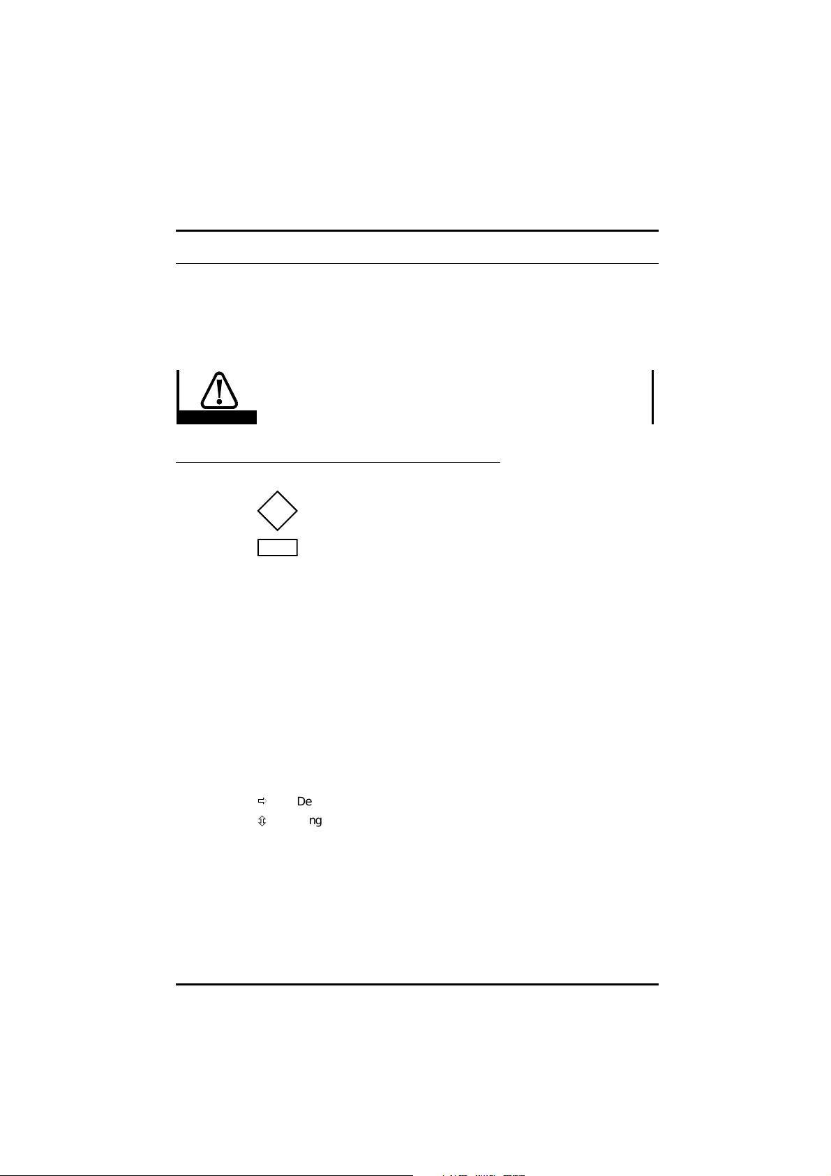
Before attempting to adjust any parameters, refer to the
Warnings and Notes at the beginning of Chapter 3 Setting up
Warning
Key
the Drive in the Unidrive User Guide.
Type of parameter
RO Read-only
RW Read–write
...selector Select from a number of settings
...enable Make or allow a function to operate
...indicator The value can only be read
Limitations of use
R The Drive must be reset for a new value to take effect.
P Protected parameter; the parameter cannot be used as the
destination parameter for a programmable input.
Range
Bi Variable parameter having bipolar value range.
Uni Variable parameter having unipolar value range.
Bit Bit parameter
Symbols
ð
Default value
ô
Range of values
~ Indicates a range of values
(in the case of bit parameters, ~ indicates or).
18
UD78 User Guide
Issue code: 78nu2
Page 23

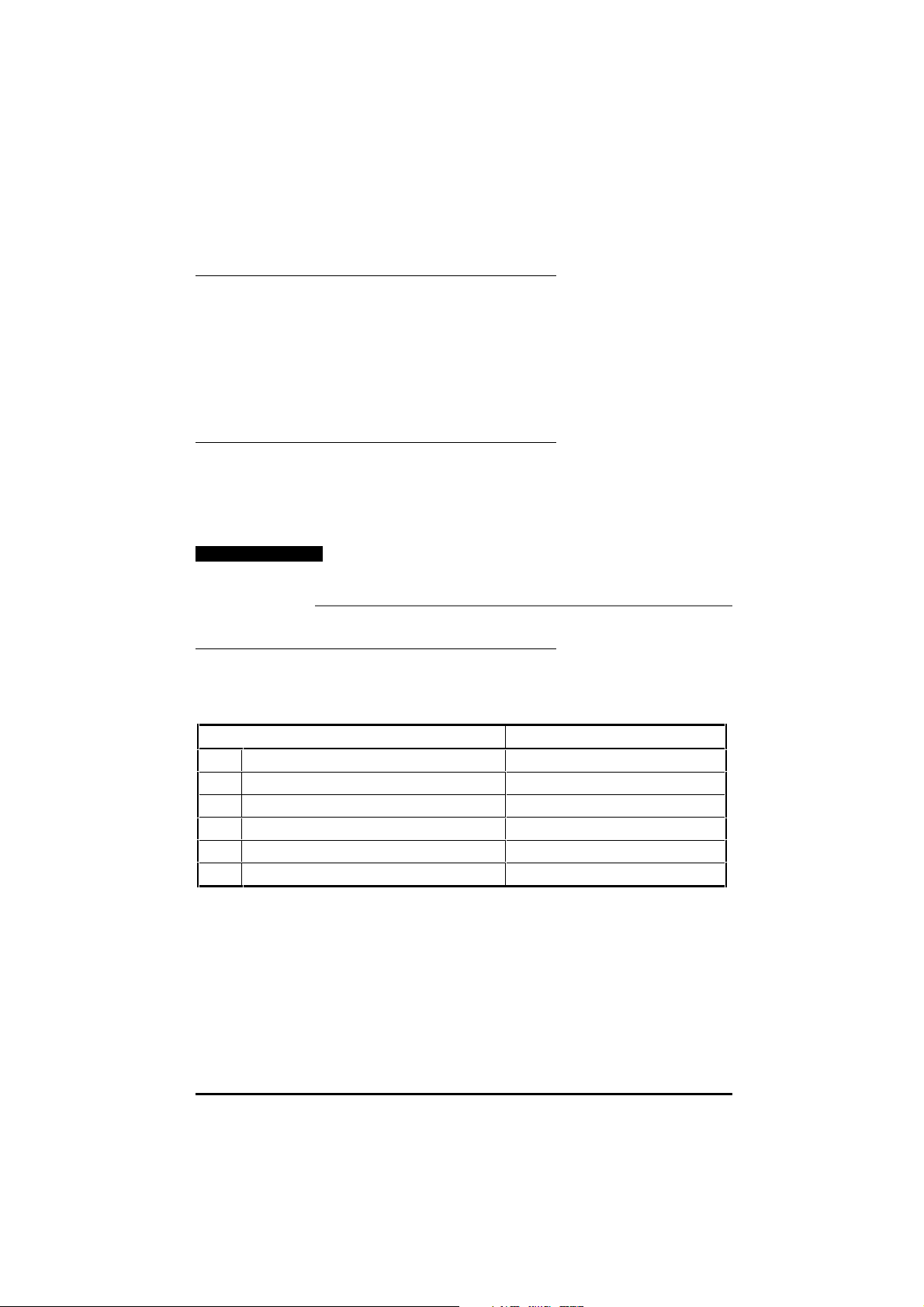
5.2 Precision analog input parameters
Precision analog
input
2
3
SK1
[UD78]
7.26
V/f sample
time
7.25
Calibrate
analog input 1
full scale
V/f
7.06
Analog input 1
mode
7.08
Analog
input 1
scaling
Analog input 1
offset trim
7.07
x(-1)
Analog input 1
7.01
Function-1
destination
selector
7.10
7.09
Any
unprotected
variable
parameter
Analog input 1
invert
??.??
??.??
The parameters are shown at their default settings.
The logic diagram is valid when
their default settings but may not be valid when certain
parameters are adjusted.
Figure 9 Logic diagram for the precision analog input
UD78 User Guide
Issue code: 78nu2
all
parameters are at
19
Page 24

7.01 Analog input 1 indicator
ô
±100
ð
% RO Bi P
7.01 indicates the value of the precision analog input after o ffset trim has
been applied by parameter 7.07 Analog input 1 offset trim. The indicated
value is a percentage of the full-scale amplitude (see parameter 7.25
Calibrate analog input 1 full-scale enable).
7.06 Analog input 1 mode selector
ô
VOLt
ð
VOLt RWTxt P
The setting of 7.06 cannot be changed.
7.07 Analog input 1 offset trim
ô
±10.000
ð
0 % RW Bi P
If an unwanted offset exists in the analog reference signal, adjust 7.07 to
cause 7.01 Analog input 1 indicator to indicate zero.
7.08 Analog input 1 scaling
ô
0 ~ 4.000
Set 7.08 at the required value to alter the scaling of the analog reference.
The scaling takes place after full-scale calibration (see parameter 7.25
Calibrate analog input 1 full-scale enable). 7.01 Analog input 1 indicator is not
affected by the setting of 7.08.
ð
1 RWUni
20
7.09 Analog input 1 invert
ô
0 ~ 1
ð
0 RW Bit
Set 7.09 at 1 to invert the value of the analog input.
7.10 Analog input 1 destination selector
ô
0.00 ~ 20.50 ð 1.36 Menu.
parameter
The default setting of 7.10 assigns terminals 2 and 3 of SK1 to 1.36 Analog
reference 1. If required, use 7.10 to change the function of the precision
analog input by entering the required menu.parame ter number (eg. 4.08 for
torque reference).
RWUni R P
UD78 User Guide
Issue code: 78nu2
Page 25

Only a variable parameter that is not protected can be specified. If any
other type of parameter is specified, the input is not assigned to any
parameter.
To make the new setting take effect, press
7.25 Calibrate analog input 1 full-scale enable
ô
0 ~ 1
ð
0 RW Bit
By default, the input is calibrated so that 9.8V sets 7.01 at 100%. Use the
following procedure to chan ge the full-scale value:
1 Apply the required full-scale value to terminals 2 and 3, as follows:
• If the applied value is greater than 2.5V, it will become the new
full-scale value
• If the applied value is less than 1.5V, the new full-scale value will be
the default value (9.8V)
2 Set 7.25 at 1.
The input scaling automatically c hanges acc ording to the applied valu e
(see step 1). This new value will set 7.01 at 100% and will remain
effective until this procedure is next performed.
The new setting is saved at power-down.
7.26 V/f sample time
Closed-loop only
When 7.10 is set at 1.36 (default), 1.37, or 3.19, if required set 7.26 for the
best compromise between low-speed operation and dynamic response.
Low values give good dynamic response but noisy operation at low speeds.
High values give smooth low-speed operation but a poorer dynamic
response.
7.31 is set at 1 when a UD78 module is fitted in the Drive.
UD78 User Guide
Issue code: 78nu2
ô
CL> 0 ~ 5.0
ð
4 ms RWUni
7.31 UD78 large option module fitted indicator
ô
0 ~ 1
ð
RO Bit P
21
Page 26

5.3 Back-up DC supply parameter
10.41Back-up DC supply active
ô
0 ~ 1
10.41 Indicates...
0 AC supply connected
Control circuits and power stages operate (Drive fully operating)
1 AC supply disconnected, back-up DC supply active
Only the control circuits operate
The Drive cannot power a motor
The Drive displays LOPS
The Drive can be programmed either manually or via serial communications,
but parameter values cannot be saved
Model sizes 1 and 2: Heatsink fan operates
Model sizes 3 and 4: Heatsink fans do not operate
ð
5.4 Serial communications parameters
11.23 Serial comms. address
ô
0 ~ 9.9
Enter the required address (group number and unit number) in 11.23. The
address cannot contain 0 (eg. addresses 01, 10, 20, 30 are not permissible).
Each UD78 on a serial communications network must have a unique address.
Up to nine groups can be created, and up to nine units can be assigned to a
group. (See Appendix A Serial communications message formats.)
ð
1.1 group.unit RWUni P
RO Bit P
22
UD78 User Guide
Issue code: 78nu2
Page 27

11.24 Serial comms. mode selector
ô
(See below)
ð
ANSI 4 (1) RWTxt R P
Set 11.24 as follows:
11.24 Mode Special parameter
ANSI 2 (0) 2-wire half-duplex
(transceiver mode)
ANSI 4 (1) 4-wire half-duplex, independent
RX and TX channels
OUtPUt (2) The Drive can control another
Drive
InPUt (3) The Drive can be controlled by
another Drive
11.26 Serial comms. 2-wire mode
delay
11.27 Serial comms. source
selector
11.27 Serial comms. destination
selector
See PL1 Serial communications connector in Chapter 4 Making Connections.
11.25Serial comms. baud rate
ô
4800 (0)
9600 (1)
19200 (2)
ð
4800 baud RWTxt P
Applicable only in ANSI 2 and ANSI 4 modes.
11.26Serial comms. 2-wire mode delay
When 11.24 is set at ANSI 2 for 2-wire (transceiver) operation, it is possible
for the UD78 to reply to an interrogation from the system controller before
the system controller returns from transmit to receive mode. If this occurs,
data will be lost.
Use 11.26 to set sufficient delay before the UD78 replies to an
interrogation.
UD78 User Guide
Issue code: 78nu2
ô
0 ~ 255
ð
0 ms RWUni
23
Page 28
11.27 Serial comms. source/destination selector
ô
0.00 ~ 20.50
ð
0 Menu.
RWUni R P
parameter
Use 11.27 to select the following...
Output mode: Required source parameter
Input mode: Required destination parameter
Output mode
Only a variable parameter can be specified.
If any other type of parameter is specified, no value is transmitted.
Input mode
Only a variable parameter that is not protected can be specified
If any other type of parameter is specified, the input is not assigned to any
parameter.
Both modes
To make the new setting take effect, press
11.28Serial comms. parameter scaling
ô
0 ~ 4.000
ð
1 RWUni
Input and output modes
If required, use 11.28 to scale the value being transmitted or received.
24
UD78 User Guide
Issue code: 78nu2
Page 29
A Serial Communications
ANSI Message Formats
A.1 Fundamentals of data transmission
Data frame
Data is transmitted at a fixed speed or baud rate in the form of a charac ter.
A character comprises seven bits.
In order for a receiver to recognize valid data, a frame is placed around each
character. This frame contains a start bit, a stop bit, and a parity bit.
Without this frame, the receiver will be unable to synchronize itself with the
transmitted data.
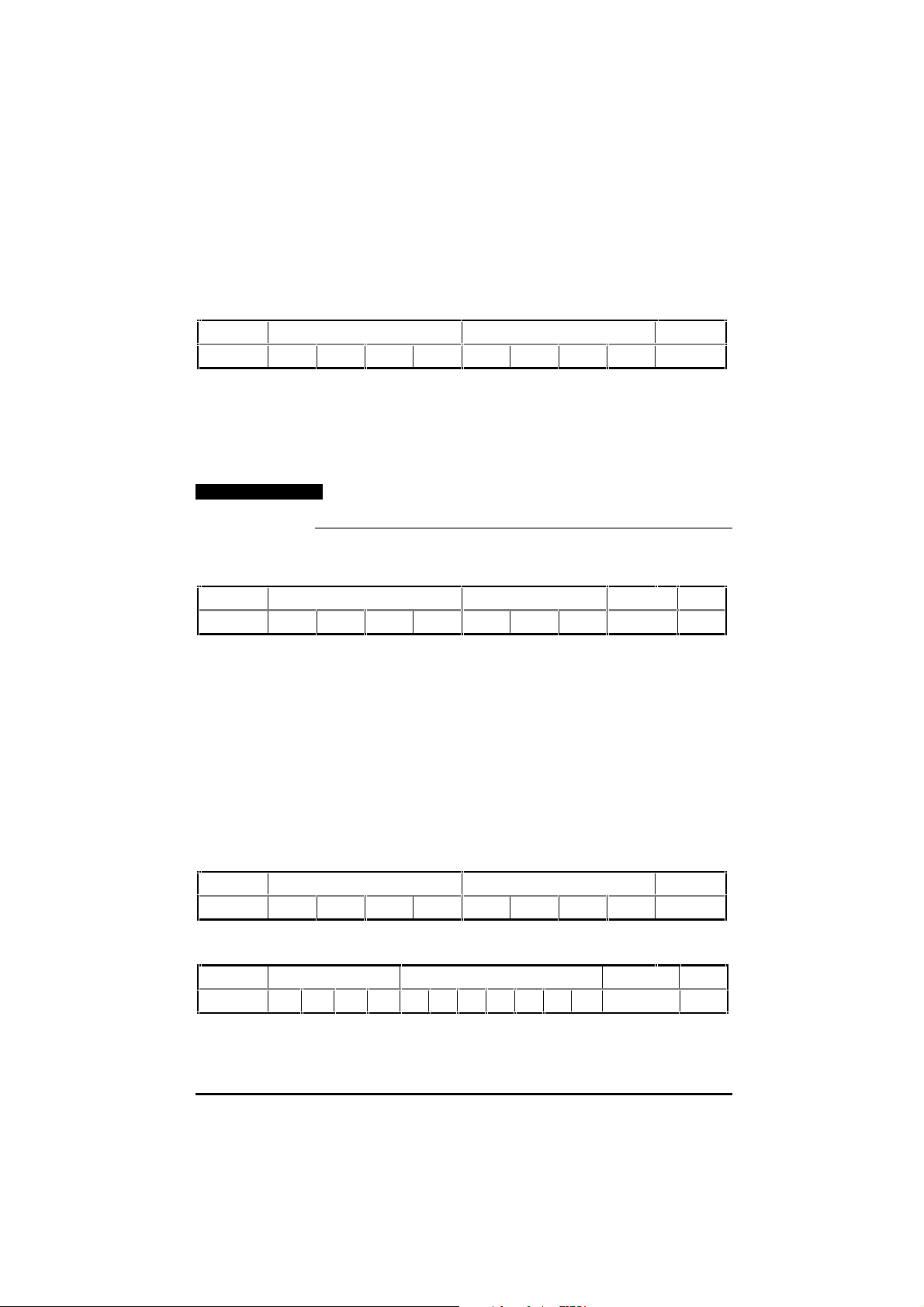
The frame used in the ANSI protocol is as follo ws:
Low ASCII character byte
1st hex character 2nd hex character
Start bit 7 data bits Parity bit Stop bit
0LSB MSB 1
This is known as a 10-bit frame, since there are 10 bits tran smitted in total.
The format is described as follows:
1 start bit, 7 data bits, even parity, 1 stop bit.
lsb refers to the least significant bit (ie. bit 0)
msb refers to the most significant bit (bit 6)
The Parity bit is used by the receiver to check the integrity of the data
it has received (even parity is used)
The character set used is called the low
characters decimally numbered from 0 to 127. The first 32 characters in the
ASCII set (hex. 00 to 1F) are used to represent special codes. These ar e the
control codes, each of which has a particular meaning (eg. start of text is
called STX and is ASCII code 02.)
ASCII set. The set comprises 128
UD78 User Guide
Issue code: 78nu2
A-1
Page 30

Control characters
Commands and requests are sent in message pac kets. Each message is
started with a special control character, and may contain additional control
characters. A list of all the control characters that can be used when a
message is being sent or received is as follows:
Character Meaning ASCII code
(decimal)
EOT Reset
Instructs the Drive to prepare for a new message.
Also indicates parameter does not exist.
ENQ Enquiry
Used when interrogating the Drive.
STX Start of text
Used to start a command.
ETX End of text
Used at the end of a command.
ACK Acknowledge (message accepted) 06 Ctrl F
NAK Negative acknowledge (message not understood) 21 Ctrl U
BS Backspace (go to previous parameter) 08 Ctrl H
04 Ctrl D
05 Ctrl E
02 Ctrl B
03 Ctrl C
Addressing
Each Drive on an ANSI communications bus must be given a unique identity
or address so that only the target Drive will respond to a com mand
transmitted by the system controller. The address comprises the following
two parts:
• Group address (first digit)
• Unit address (second digit)
Both the group address and unit address have a range of 1 to 9. A group or
unit address of 0 is not allowed (addresses 01, 10, 20, etc. are invalid). The
reason for this is that Drives can be grouped together (up to 9 units per
group), and a message can be sent over the
units of the group. To address a particular group, the unit address zero (0)
is used. For example, to address all units of group 6, the full address will be
60.
An additional feature is that a message can be sent to all units of all groups
simultaneously using the address 00. This address can be used to send a
Start command to a group of Drives which are mechanically coupled
together to drive a conveyer line. All the Drives will then start
simultaneously.
ANSI communications bus to all
Keyed as...
A-2
UD78 User Guide
Issue code: 78nu2
Page 31

Note
It is important to realize that when using group
addressing, the Drives will not acknowledge the command.
(If several Drives try to reply at the same time, they would
cause meaningless data to appear on the serial
communications bus.)
For security, the format of the transmitted address requires that each digit
of the two-digit address is repeated: the address of Drive number 23 is sent
as four characters, eg:
2 2 3 3
The serial address follows immediately after the first control character of
the message (
Parameter identification
For transmission of their values, all parameters are identified by four digits
representing the menu and the parameter number, but witho ut the decimal
point.
EOT).
Example
To send a message to menu 4, parameter 26, write 0426 (the leading zero
must be included)
To send a message to menu 16, parameter 3, write
Data field
Data to be sent or requested occupies the charac ters immediately after the
parameter number. The minimum len gth of the data field within a message
structure is two characters.
The data is normally expressed as a decimal numeric valu e; the first
character of the data field (
Space (32 dec.)
+
–
Block checksum (BCC)
In order to protect the system against messages that have beco me
corrupted in transmission, all wr ite messages and data respo nses are
terminated by the block checksum character (BCC). See Calculating the
block checksum (BCC) later in this appendix.
1603.
D1) can be only one of the following:
UD78 User Guide
Issue code: 78nu2
A-3
Page 32
A.2 Reading a parameter value
To read the value of a parameter, the following message is sent:
Control Address Parameter Control
EOTGAGAUAUAM1M2P1P2ENQ
Where:
GA = Group Address
UA = Unit Address
M1 M2 = Menu number
P1 P2 = Parameter number
Note
No BCC character is sent in this message.
The Drive will reply with the following structure if the message is
understood:
Control Parameter Data Control BCC
STX M1 M2 P1 P2 D1 ... Dn ETX BCC
Where:
M1 M2 = Menu number
P1 P2 = Parameter number
D1...Dn = Data
First character:
+ or Space for positive values
– for negative values
BCC = Block checksum
If a requested parameter does not exist, the Drive will reply with an
character (ASCII 04).
EOT
Example
Control Address Parameter Control
STX11220121ENQ
To read the value of parameter 1.21 in a Drive that is unit 2 of group 1, send:
The Drive replies as follows:
Control Parameter Data Control BCC
STX 0121–0047.6 ETX 7
UD78 User Guide
A-4
Issue code: 78nu2
Page 33

A.3 Re-reading a parameter value
Once a read message has been received and understood (ie. valid data was
returned), to request the parameter value again, request the value of the
next parameter, or the previous parameter, a single control code character
may be sent. These control codes are as fo llows:
Control code Function Keyed as...
NAK Return the value of the same parameter Ctrl U
ACK Read the next parameter Ctrl F
BS Read the previous parameter Ctrl H
This facility can be used to save time when monitoring a parameter over a
period of time.
A.4 Writing a parameter value
To write a value to a parameter, the message structure is com prised
as follows:
Control Address Control Parameter Data Control BCC
EOT GAGAUAUA STX M1M2P1P2D1 ...Dn ETX
Where:
GA = Group address
GU = Unit address
M1 M2 = Menu number
P1 P2 = Parameter number
D1...DN = Data
First character:
+ or Space for positive values
–– for negative values
BCC = Block checksum
The data field can be of a variable length with the maximum length bein g
dependent on the parameter being edited.
The Drive will respond with a single control character, as follows:
Control code Meaning
ACK Acknowledge — Message has been understood and implemented.
NAK Message invalid
Data is too long or out of range
Parameter is invalid
Parameter is read-only
BCC is incorrect
UD78 User Guide
Issue code: 78nu2
A-5
Page 34

Example
Control Address Control Parameter Data Control BCC
EOT 2 2 6 6 STX 0 1 2 5 + 0 7 6 . 4 ETX %
To set parameter 1.25 at +76.4 for a Drive that is unit 6 of group 2, send:
A.5 Re-writing a parameter value
Once a write message which includes the address field has been sent to a
Drive and accepted with either a <ACK> or <NAK> response, subsequent
write messages to that particular Drive can use a r e-write message struc ture
in which the address does not need to be re-transmitted. The re-write
structure is as follows:
STX M1 M2 P1 P2 D1 ... Dn ETX BCC
When a different Drive is addressed, or an invalid character is received, the
re-write facility no longer functions. The first Drive can be addressed again
only by using the full write message with the address.
A.6 Calculating the block checksum
(BCC)
The block checksum is calculated by applying an exclusive OR function to all
of the characters of a message after the STX control character.
XOR truth table
ABOut
000
011
101
110
A-6
Example
To set parameter 1.25 at –34.5
The first character of the
of which is taken as a starting or result value. The next character is 1
(00110001 in binary), which now has the exclusive OR (XOR) operator act
upon it. With the previous result value, a new result occurs of 00000001 in
binary.
BCC calculation is 0 (00110000 in binary), the value
UD78 User Guide
Issue code: 78nu2
Page 35
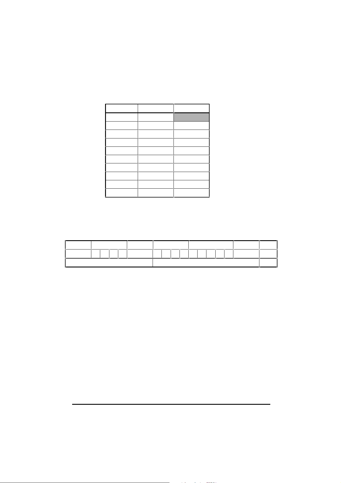
The complete calculation is show in the table below:
Character Binary Value XOR result
0 0011 0000
1 0011 0001 0000 0001
2 0011 0010 0011 0011
5 0011 0001 0000 0110
– 0010 1101 0010 1011
3 0011 0011 0001 1000
4 0011 0100 0010 1100
. 0010 1110 0000 0010
5 0011 0101 0011 0111
ETX 0000 0011 0011 0100
The final value is the BCC, provided that its equivalent decimal value exc eeds
31 (ASCII characters from 00 to 31 are used as control codes).
When the final
XOR result produces a decimal value less than 32, 32 is added.
In this example, 0011 0100 is 52 decimal which is above 31, so this is the final
BCC value. 52 decimal is the character 4. The complete message will be as
follows:
Control Address Control Parameter Data Control BCC
EOT 1 1 2 2 STX 0 1 2 5 – 3 4 . 5 ETX 4
Not included in the calculation Included in the calculation Result
Example
QuickBasic program to calculate BCC
UD78 User Guide
Issue code: 78nu2
mess$ = CHR$(4)+”1122”+CHR$(2)+”0125”+”-34.5”+CHR$(3)
bcc% = 0
FOR n% = 7 to LEN(mess$)‘start at the character after ‘chr$(2).
bcc% = bcc% XOR ASC(MID$(mess$, n%, 1))
NEXT
IF bcc% < 32 THEN bcc% = bcc% + 32
mess$ = mess$ + CHR$(bcc%)
PRINT mess$
A-7
Page 36

A-8
UD78 User Guide
Issue code: 78nu2
Page 37

B Setting up the Drive using UniSoft
The UniSoft package is a Windows-based Drive set-up and commissioning
program that is designed to enable complete control and display of all
parameters in a Unidrive. UniSoft provides the user with a graphical
interface that is logically split into a series of screens, offering quick and easy
viewing and, where appropriate, editing of a parameter value. Individual
detailed parameter information can at any time be displayed defining the
parameters function, type and min/max permitted valu e.
Unisoft is available from your local Drive Centre.
PCs have an RS232 serial communications interface. To enable the PC to
communicate with the Drive, either of the follo wing must be used:
• RS232 to RS485 converter.
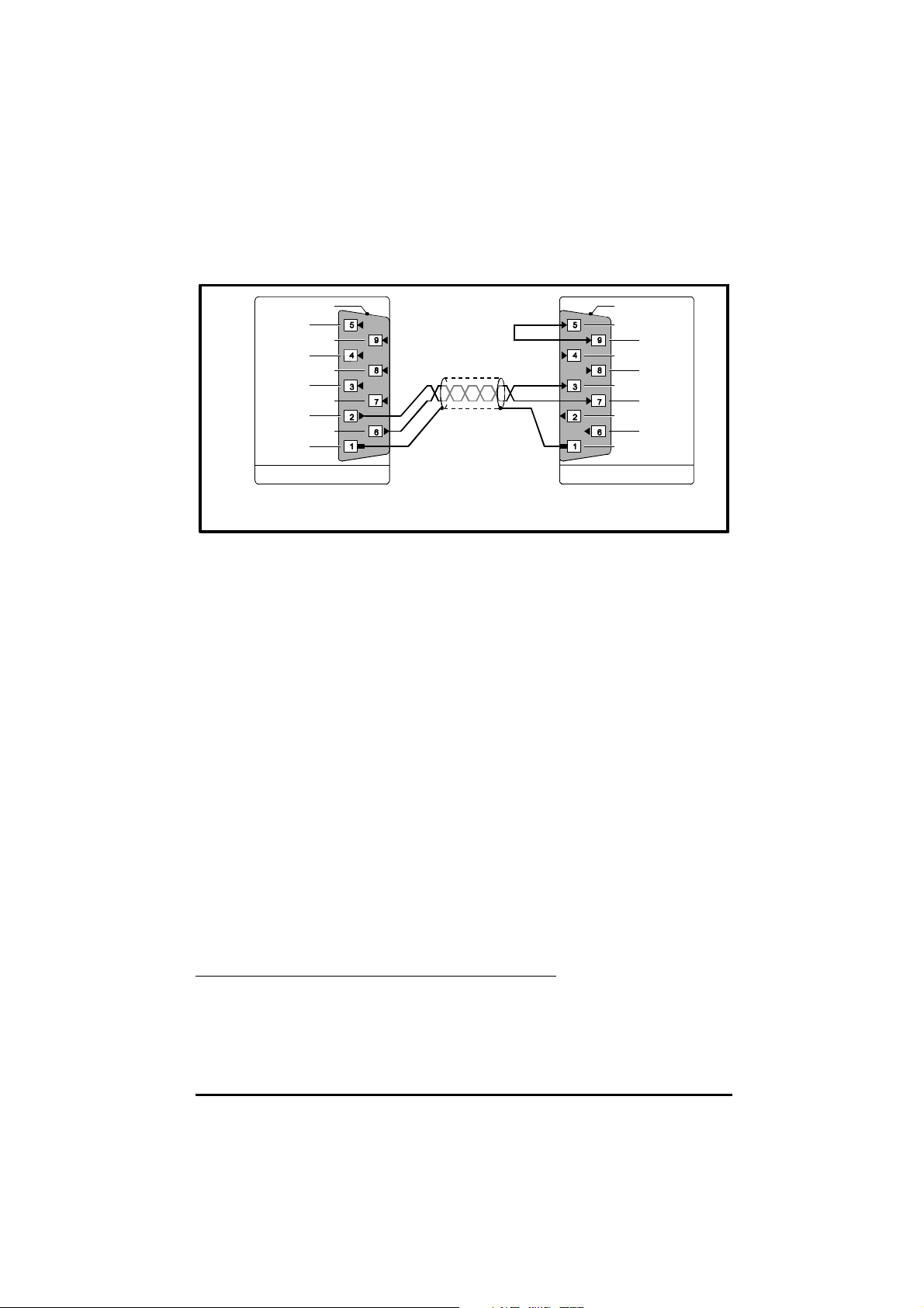
• A special serial communications cable having the connections
shown below:
PC UD78
Terminal Name Terminal Name
–––– 1 0VSC
50V–––– 6 TX
–––– 7 RX
2RXD–––– 2 TX\
3TXD–––– 3 RX\
Connect terminals 1, 6, 7 of the UD78 together.
Recommended maximum cable length: 3m (10 ft)
Note
UD78 User Guide
Issue code: 78nu2
The special serial communications cable connected as
shown above must be used only for temporary connection
to the Drive. It must not be used for permanent
installations.
B-1
Page 38

B-2
UD78 User Guide
Issue code: 78nu2
 Loading...