

Page 1

User Guide
UD77
DeviceNet
Option Module
For Uni dri ve
Part Number: 0460-0077
Issue Number: 2
Page 2

!
SAFETY INFORMATION
Persons supervising an d performing the electric al installation or maintenanc e of a
Drive and/or an exter nal Option Unit mus t be suitably qualified and c ompetent in
these d uties. T hey should be given t he opport unity to s tudy and i f necess ary to
discuss this User Guide before work is started.
The volt ages pr es ent in the Dr ive an d ext ern al Opt ion U nits are cap able of i nflic ting
a severe electric shock and may be lethal. The Stop function of the Drive does not
remove dangerous voltages from the terminals of the Drive and exter nal Option
Unit. Mains supplies should be removed before a n y se r vicing work is performed.
The inst allation ins tructi ons should b e adhered t o. Any questi ons or doubt s hould
be referred to the supplier of the equipment. It is the responsibility of the owner or
user to ens ure that th e installation of the Drive and external O ption Unit, and the
way in whic h they are op erated and maintain ed complies with the req uirements of
the Healt h an d Saf ety at W ork Act i n the U nit ed Ki ngd om and applicable l egis lati on
and regul ati ons an d c od es of pr act ice in the UK or elsewh ere.
The Drive software may incorporate an optional Auto-start facility. In order to
prevent the risk of injury to personnel working on or near th e motor or its driven
equipm ent and to prevent pot ential dam age to equipm ent, users and oper ators, all
necess ar y precauti ons m us t be tak en if operating t h e Dr i ve in th is m o d e.
The Stop and St art inp ut s of t he Drive should n ot b e r elied upon to ensure safety of
personn el. If a safety haz ard coul d exist from une xpect ed st arting of th e Drive, an
interlock should be in stalled to pre vent the motor be ing inadverte ntly started.
GENERAL INFORMATION
The manufacturer accepts no liability for any consequences resulting from
inappropriate, negligent or incorrect installation or adjustment of the optional
operating parameters of the equipment or from mismatching the Drive with the
motor.
The contents of this User Guide are believed to be correct at the time of printing. In
the interests of a commitment to a policy of continuous development and
improv em en t, the m an ufacturer res erves th e right to chan g e the sp ec if ic ation of th e
product or its performance, or the contents of the User Guide, without notice.
All rights reserved. No part of this User Guide may be reproduced or transmitted in
any form or by any means, electrical or mechanical including photocopying,
recordin g or by any inform ation storage or retri eval syst em, without permissi on in
writing f r om th e pu blisher.
Copyright © January 2001 Control Techniques SSPD
Author Paul Bennett
Issue Code Issue 2
System File V2.07.03 or later
Hardware (UD77) UD77 A Issue 2, UD77 B Issue 4, UD77TB Issu e 01.00
Firmware (UD77) V2.00.00
Page 3

Contents
1 Introduction 7
1.1 DeviceNet Interface for Unidrive 7
1.2 Product Conformance Certification 7
1.3 Overview Specification 7
2 Mechanical Installation 8
2.1 Unidrive 8
3 Electrical Installation 9
3.1 DeviceNet Connectors 9
3.2 DeviceNet Connections 10
3.3 DeviceNet Cable 10
3.4 DeviceNet Cable Screen Connections 10
3.5 DeviceNet Networ k Termi n atio n 11
3.6 Maximum Network Length 12
3.7 External Power Supply 12
4 Getting Started 13
4.1 Basic Communications Quick Start 13
4.2 DeviceNet Node Address 13
4.3 DeviceNet Data Rate 14
4.4 Product Code Elaboration 14
4.5 Data Format 14
4.6 Node Status 15
4.7 Network Status 15
4.8 Network Loss Trip 16
4.9 Initialising Set-up Changes 16
5 Polled Data 17
5.1 What is Polled Data?? 17
5.2 DeviceNet Data Format 17
5.3 Mapping Parameters on Unidrive 18
5.4 Internal 32-Bit Parameters on UD70 18
5.5 Storing Parameters 19
5.5.1 Saving Unidrive Parameters (Menu 1 to 19) 19
5.5.2 Saving UD70 Parameters (Menu 20 and Internal) 19
5.6 Mapping Conflicts 20
5.6.1 Control Word Mappi ng Conf lic ts 20
5.7 Fieldbus Control Word for Unidrive 21
5.8 Fieldbus Status Word for Unidrive 23
5.9 Disabling Cyclic Data Channels 23
6 Explicit Data 24
6.1 Exp licit P a rame ter Ac c ess 24
Page 4

7 Support Files 25
7.1 What are EDS Files? 25
7.2 Generic EDS Files 25
7.3 EDS File Revisions 26
7.4 Advanced EDS Files 26
8 Diagnostics 27
8.1 Fieldbus Code 27
8.2 Firmware Version 27
8.3 System File Version 28
8.4 Node Address 28
8.5 Network Data Rate 28
8.6 Number of Network Messages 28
8.7 Node Status 29
8.8 Network Status 29
8.9 No Data Transfer 29
8.10 Unidrive Trip Codes 30
9 Advanced Features 31
9.1 Network Loss Trip 31
9.2 Unidrive Sequencing Mode 3 32
9.3 Drive Reset Using The Devic eNet Network 33
9.3.1 Reset Without DPL Code 33
9.3.2 Reset Using Explicit Communications 33
9.3.3 Reset Using DPL Code 34
9.4 Non-Cyclic Parameter Store 34
9.5 EVENT Task Trigger on UD70 35
9.6 Multi-Master Networks 35
9.7 Supported Drive Prof iles 35
9.7.1 Basic Speed Control 36
9.7.2 Extended Speed Control 37
9.7.3 Basic Speed and Torque Control 37
9.7.4 Extend ed S p eed and Torque Control 38
9.7.5 Basic Speed Control 38
9.7.6 Basic Speed and Torque Control 39
9.8 Object Model 39
9.9 Iden tity Obje ct 40
9.9.1 Vendor ID 40
9.9.2 Device Type 40
9.9.3 Product Code 40
9.9.4 Revision 41
9.9.5 Status 41
9.9.6 Serial Nu mber 41
9.9.7 Product Name 41
9.10 DeviceNet Object 42
9.10.1 MAC-ID 42
9.10.2 Dat a Rat e 42
9.10.3 Bus Off Interrupt 43
9.10.4 Bus Of f Counter 43
Page 5

Allocati on Byte 43
9.10.5
9.11 Control Supervisor Object 44
9.11.1 RunFwd 44
9.11.2 RunRev 45
9.11.3 NetCtrl 45
9.11.4 RunningFwd 45
9.11.5 RunningRev 45
9.11.6 Ready 46
9.11.7 Faulted 46
9.11.8 FaultRst 46
9.11.9 FaultCode 46
9.11.10 OutputAssembly 47
9.11.11 InputAssembly 47
9.11.12 DriveEnable 48
9.11.13 ZeroParam 48
9.12 AC/DC Drive Object 48
9.12.1 AtReference 49
9.12.2 NetRef 49
9.12.3 DriveMode 49
9.12.4 SpeedActual 49
9.12.5 SpeedRef 50
9.12.6 TorqueActual 50
9.12.7 TorqueRef 50
9.13 Motor Data Object 50
9.13.1 MotorType 51
9.13.2 RatedCurrent 51
9.13.3 RatedVoltage 51
9.14 Control Techniques Object 51
10 Quick R eference 53
10.1 Complete Parameter Reference 53
10.2 DeviceNet Data Format 53
10.3 Fieldbus Control Word 54
10.4 Fieldbus Status Word 55
10.5 Unidrive Trip Codes 56
Page 6

Page 7

1 Introduction
NOTE
Unidrive paramet ers are denoted i n this ma nual by “ #MM .PP”, where
MM refers to the menu number, and PP refers to the parameter
number wi thi n that menu. Plea se ref er to t he Un idri ve Ad vanc ed User
Guide for a ful l list of parameter de f i ni t i o ns.
1.1 DeviceNet Interface for Unidrive
The Unidr ive Devi ceNet int erf ace is suppl ied as an opt ion m odule, wi th
the Devic eN et usi ng a UD 70 as th e host. T h e UD70 d oes n ot los e any
functi onality when the DeviceN et interfac e is fitted. T he fastest d ata
rate curr ent l y sup p or t ed i s 5 00 Kb its/sec.
The Unidrive supplies all power requirements for the Unidrive
DeviceNet interface. A DeviceNet network power supply must also be
connected, but this power supply does NOT keep the UD70 powered up
when the Unidrive is switched off.
1.2 Product Conformance Certification
The Uni dri v e D e viceNet int erface w as sub mi t ted to the O pen DeviceNet
Vendors Association for conformance testing. All tests were successful,
and the Unidrive DeviceNet interface was awarded full DeviceNet
Conformance Certification. Refer to the ODVA Web Site at
“www.odva.org“for further details.
1.3 Overview Specification
• Supported data rates (bits/sec): 500k, 250k, 12 5k
• T hree polled 16 bit input/ou tput words, all can be mapp ed to and
from Unidr i ve para mete rs
• Explicit data allows access to all Unidrive parameters
• 6 DeviceNet Drive Profiles supported
Issue Number: 2 7
Page 8
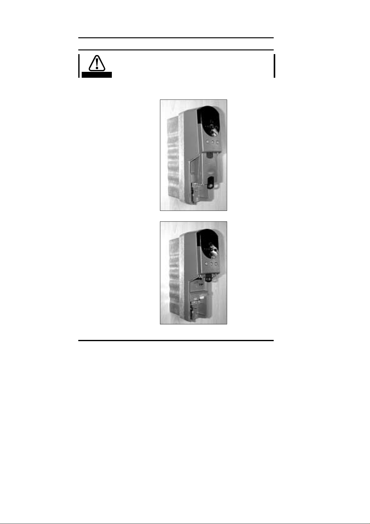
2 Mechanical Installation
The Unidrive must be disconnected from the mains supply
before installing or removing an option module.
Warning
2.1 Unidrive
1. Sli d e the option modu l e into the Unidri ve.
2. Pus h th e opt ion modul e int o th e Uni dr i ve u ntil it clicks into place.
8 Issue Number: 2
Page 9

3 Electrical Installation
3.1 DeviceNet Connectors
The Unidrive DeviceNet Interface provides a standard 5-way screw
terminal socket (A) to connect to the DeviceNet network. A small
converter board in provided to convert from the 9-way D-type connector
Connectors C and D on th e U nid r i ve D eviceNet int er face are th e RS 23 2
(C) and RS485 (D) ports of the UD70.
12345
AB
D
C
The pin c onnect ions f or th e D evic eN et c onnec tor ar e gi ven in t he t abl e
below. (Pins are numbered 1 to 5 from left to right on the above
diagrams.)
Terminal Signal Function
1 0v 0V Isolated
2 CAN_L Negative data line
3 SHIELD Cable braided shield connection
4 CAN_H Posi t ive data line
5 VDC +24V DeviceNet power supply
Issue Number: 2 9
Page 10
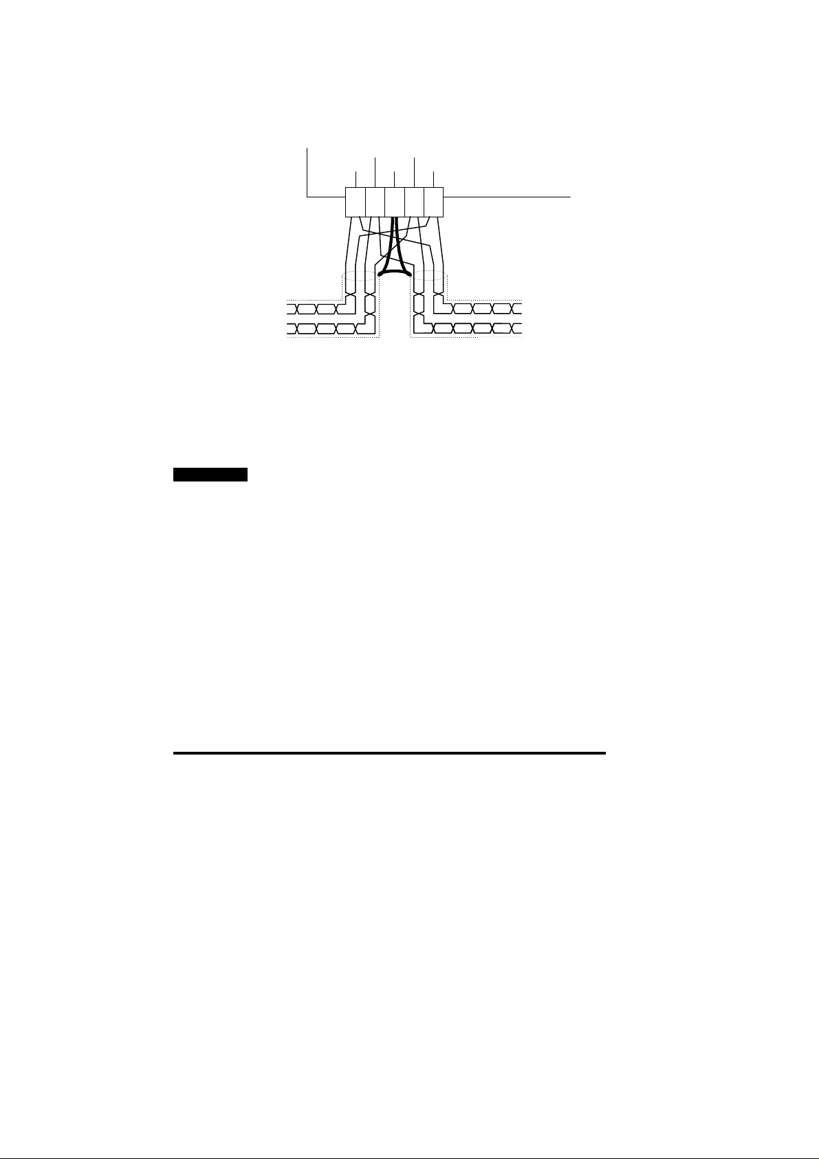
3.2 DeviceNet Connections
To conn ect the Commander SE to the Devic eNet networ k, make th e
connect ions as s hown in t he di agr am b elow. Th e leng th of th e "pi gtail"
shiel d connect ion should be ke pt as shor t as possible.
CAN-L CAN-H
0V +24VShield
1 2 3 4 5
3.3 DeviceNet Cable
Devic eNet n et works (lik e mos t f ieldbus s ystems ) r un at hi gh d ata r at es,
and consequently require cable specifically designed to carry high
frequency signals. Low quality cable may attenuate the signals, and
thus render the signal unreadable for the other nodes on the network.
Details of app roved cables t ypes and their manuf acturers can be found
on the Open DeviceNet Vendors Association web site at
“www.odva.org”.
NOTE
The Open DeviceNet Vendors Association and Control Techniques
can only guarantee correct and reliable operation of a DeviceNet
network if all components (including the network cable) installed have
full Product Conf orm an ce Certi f ic ati on from the OD VA.
0V
+24V
CAN-L
CAN-H
3.4 DeviceNet Cable Screen Connections
The Uni dri ve Devic eN et i nt er f ace shoul d be wired wit h th e cable sh i elds
isolat ed from ear th at each D rive. Th e cable sh ields sh ould be lin ked
together at the point where they emerge from the cable, and formed into
a short p igtail to be c onnected to p in 3 on the D eviceNet conn ector.
(See section 3.2)
10 Issue Number: 2
Page 11
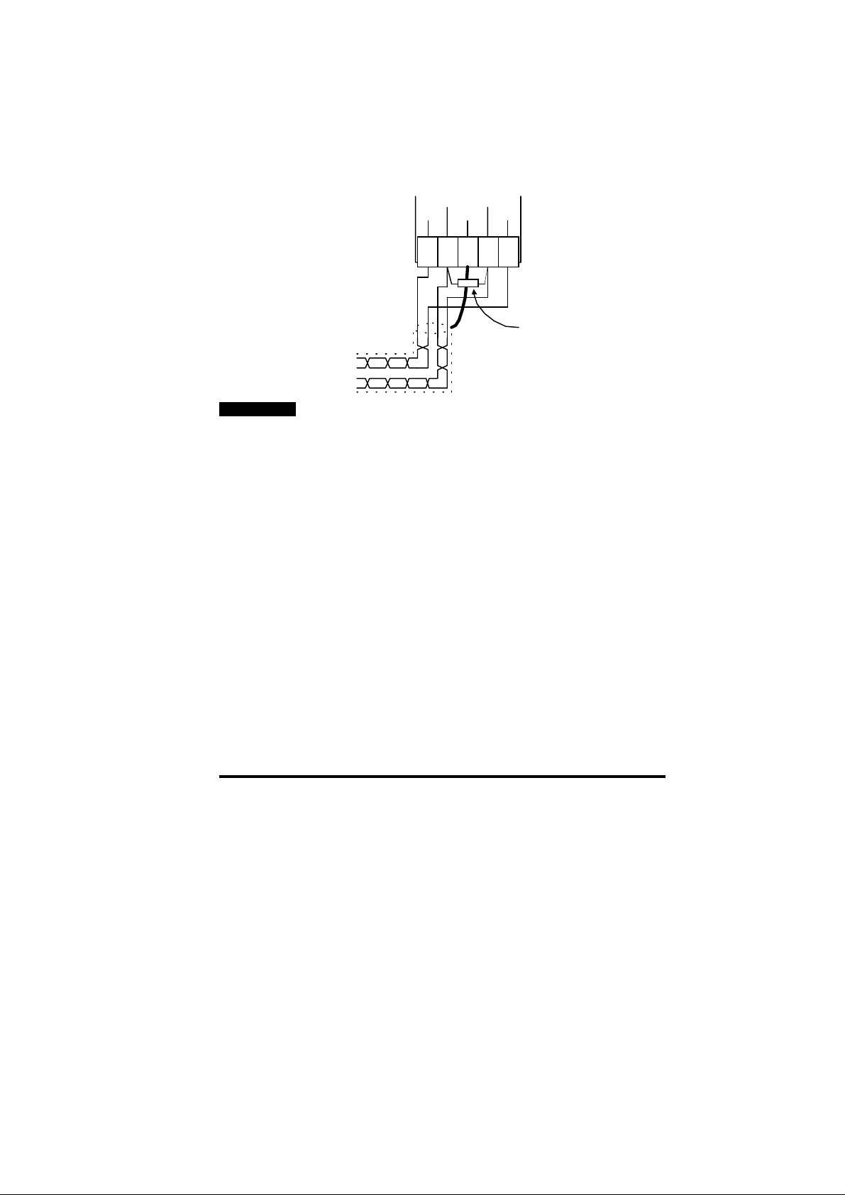
3.5 DeviceNet Network Termination
There is no termination resistor supplied on the Unidrive DeviceNet
interf ace. It is the us er’s res pons ibi lit y to ensu re that both en ds of each
secti on of n etwork c abl e are c or r ect l y t er mi n ated.
A 120Ω 0. 25W resistor shoul d be c onnect ed bet ween the CAN _H an d
CAN_L lines at each end of the main trunk cable, as shown in the
diagram below.
CAN-L CAN-H
0V +24VShield
1 2 3 4 5
Fit 120W 0.25W network
termination resistor between
CAN- L and CAN-H
0V
+24V
CAN-L
CAN-H
NOTE
The above method of connecting the termination resistor ensures that
the network remains terminated when the DeviceNet connector is
disconnected from the node.
It is very important in high-speed communications networks that the
network communications cable is correctly terminated. Failure to
terminate the network properly may mean that the network operates
with substantially reduced noise immunity, or in the worst case, the
network does n’t work at all.
Issue Number: 2 11
Page 12

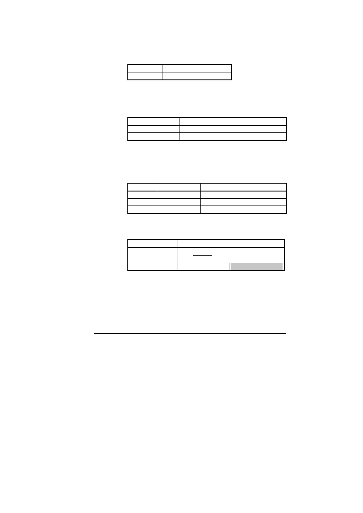
3.6 Maximum Network Length
The data rat e that can be us ed depends m ainly on the leng th of cable
that is b eing used in t he netw ork, so th e physic al layou t of th e network
must be considered during the network design stage of a project.
Data Rate (bits/sec) 125K 250K 500K
Max Trunk Distance 500m 250m 100m
Max Drop Length 6m 6m 6m
Cumulative Drop Length 156m 78m 39m
Number of Nodes 64 64 64
Devic eNet n etworks usu ally consist of a main ter minated tr unk cable
length, with a s eries of dr op c able l engt hs ( w ithou t ter min ati on) ru nning
off the main trunk cable.
For a detailed description about the limitations and requirements for
installing a DeviceNet network, refer to Allen Bradley Publication
Number DN-6.7.2. (This docu ment is avai lable fr om the Allen Br adley
web site at “www.ab.com”.)
3.7 External Power Supply
An external isolated +24V power supply is required to power the
transc ei ver ci r c uits in t h e DeviceNet n od es . Th e phys ical location of the
extern al +24V power supply can be very import ant, particul arly if the
networ k has several nodes th at dr aw signific ant power fr om th e su pply.
The Unidr ive DeviceNet int erface is powered b y the Unidrive internal
power supply. However, the external +24V power supply must be
connected to meet ODVA specifications. Each Unidrive DeviceNet
interface draws 5 mA max from the exter n al suppl y.
For detailed instructions on designing the layout of the network and
determining power supply requirements, Allen Bradley Publication
Number DN-6.7.2. (This docu ment is avai lable fr om the Allen Br adley
web site at “www.ab.com”.)
12 Issue Number: 2
Page 13

4 Getting Started
The Quick Start section shows the basic parameter configurations
required for the DeviceNet interfaces to establish communications.
Polled an d Exp lic it data exp lanations ar e gi ven i n chapters 5 and 6.
NOTE
Parameters #20.01 to #20.20 and #20.50 are reserved for configuring
the DeviceNet interface, and should not be used in DPL programs.
4.1 Basic Communications Quick Start
DeviceNet communications can be established with the Unidrive
Devic eNet interf ace simpl y by configur ing the n ode addr ess and data
rate.
• Plug the De viceNet module into the Unidrive.
• Power up the Unidrive.
• S et the MAC-ID (n od e ad dress) in #2 0. 05 as required.
• Set the Data Rate in #20.08 as required.
• Ensure Product Code Elaboration (#20.12) is set to 0.
• Set #17.19 to 1 to store and reset the UD70.
The DeviceNet interface will re-initialise, and configure itself with the
new node add ress and dat a rate.
Function Unidrive Recommended
Node Address #20.05 1 to 62
Data Rate #20.08 0 to 2
Network Loss Tri p #20.11 48
Product Code
Elaboration
#20.12 0
Setting
4.2 DeviceNet Node Address
Unidrive: #20.05
Every node must be given a unique network address. If a node is
assign ed an ad dress , and t hat ad dr ess alr eady e xists on the D evic eN et
network, the node will not join the network. The valid range of
addresses is fr om 1 an d 25 5.
Issue Number: 2 13
Page 14

4.3 DeviceNet Data Rate
Unidrive: #20.08
All nod es on D eviceNet mus t be configured to run at the same data
rate. The range of data rates available is shown in the table below.
#20.08 Data Rate
0 125K
1 250K
2 500K
(bits/sec)
4.4 Product Code Elaboration
Unidrive: #20.12
Ensure that this parameter is set to 0. For details on using this
parameter, refer to section 7.4.
4.5 Data Format
The Unidr ive D eviceNet interf ace has a d ata form at of 3 Poll ed Wor ds,
as used on M entor II and C ommander S E. Each poll ed data word is
mapped to a U nidrive parameter with default mappings as shown in the
table below.
Cyclic
Channel
IN Word 0 Status word
IN Word 1 Post-ramp speed reference
IN Word 2 Motor active current
OUT Wor d 0 Con t rol wo rd
OUT Word 1 Digital speed reference 1
OUT Wo rd 2 Torq u e reference
Default Mapping Status
14 Issue Number: 2
Page 15

4.6 Node Status
Unidrive: #20.09
When the Un idrive is p owered up, th e Devic eNet interf ace will in itialis e
the inter nal hardwar e, and go into the standb y mode. The n ode will
switch to “Operational” mode when the master controller starts
communicating with the node.
#20.09 Status Description
1 Operational The node is configured, and is
2 Standby mode The node is configured and on-line,
5 No =+24V external
power supply
10 Hardware fault Internal hardwar e err or , the DeviceN et
4.7 Network Status
Unidrive: #20.10
When the Unidrive is powered up, and the DeviceNet interface has
initialis ed, th e node will attem pt to j oin the n etwor k. If an other n ode is
detected with th e sam e MAC-ID , it will not joi n th e netw ork .
#20.10 Status Description
1 Offline The node is offline. Check the wiring,
2 Online, not connected The node is on-line, but has not been
3 Online, connected The node is on-line and connected to
4 Online, connection
time-out
10 Critic al lin k f ail ure Internal hardwar e failure
communicating with a master
controller
but has not been initialised by a
master controller
The external +24V power supply is
not connected. This powe r supply
MUST be connected for the Unidrive
DeviceNet interface to operate
interface could n ot b e ini ti alised
and that there is no node with the
same MAC-ID
initialised by a mast er c ontroller
a master c ontroller
The polled connection is in the timed-
out st ate, or a Bus Off error has
occurred, The node should have
tripped either tr62 )if enabled) of tr60
Issue Number: 2 15
Page 16

4.8 Network Loss Trip
Unidrive: #17.14
If the DeviceNet network stops operating, the interface will trip the
Unidrive on "tr60". The default time delay between network loss and
Unidri ve trip is 48ms , so the act ual delay t o trip will be between 4 8ms
and 96ms . (See sect ion 9.1 for mor e details.) T he master c ontroll er
will autom aticall y det ect that the sl ave node h as gone mis sing fr om the
networ k, and w ill update relevant s t at us r egis ters.
NOTE
Changes to #17.PP parameters in the Unidrive do not take effe ct until
the UD70 h as b e en r es et. See section 4. 9.
4.9 Initialising Set-up Changes
UD70 (#1 7.PP) and D eviceNet ( #20.PP) conf iguration parameters are
only read dur ing t he in iti alis ati on s equenc e of the U D70. T his prev ents
corruption of the configuration while parameters are being edited.
When p arameters h ave been conf igured, the UD 70 must b e reset to
implement any changes made to the configuration parameters.
To reset f rom the UD70, set #M M.00 to 1070 , and press the red RE SET
button on the Unidrive. Any changes made to the DeviceNet
configu ration will n ow t ak e effect.
NOTE
Resetting the UD70 does not store the #20.PP configuration
parameters, so these changes will be lost when the Unidrive is
powered down. See section 5.5.2 for details on how t o store UD70
parameters.
16 Issue Number: 2
Page 17

5 Polled Data
The def aul t DeviceN et c onf ig uration c ontains thr ee 16-bit IN data words
and thr ee 16-bit O UT data words. Th ese data w ords are class ed as
“polled d ata channels ”.
NOTE
“OUT dat a” and “IN data” descr ibe the dir ection of dat a transfer as
seen by the PLC scanner.
5.1 What is Polled Data??
Polled data is a method data transfer that must be set-up during
network configuration, but is transmitted automatically once
configu rati on is c om pl ete. T he hi gh-s pe ed d ata tr ansf er is achie ved by
transmi tting only a 16-bit dat a value for each poll ed chann el over the
Devic eNet netw ork, and relying on loc al mappi ng infor mation w ithin th e
Unidrive to ensure the correct data is sent to the correct locations. This
method relies on the PLC progr am writing and r eading data v alues to
and from the registers allocated to the node during network
configu rati on, an d the sourc e and dest in ation of IN an d OUT data being
set-up correctly in the Unidrive itself.
The flexibility of the Unidrive DeviceNet interface means that each
polled data OUT channel c an be directed to any read-write Unidrive
parameter. Similarly, each polled data IN channel can use any Unidrive
parameter as a source of data.
NOTE
The mapping configuration cannot be changed dynamically, as the
UD70 must be re set bef ore change s to th e ma pping beco me ac tive.
5.2 DeviceNet Data Format
The Unidrive Devic eNet interface has a data format of 3 polled data
words. Explicit data must be used for non-cyclic communications.
Non-cyclic
mode
Explicit 3 This is the same data format as Mentor II,
Issue Number: 2 17
Polled
words
Comments
and Form at 0.03 on Com m an d er SE
Page 18

5.3 Mapping Parameters on Unidrive
The m apping for the cyclic data ch annels on the Unidr ive DeviceNet
interface can be set from the Unidrive keypad using #20.PP
parameters.
The mapping method is similar to the method used for mapping
analogue inputs and outputs. The value entered in the mapping
parameter takes the form MMPP, where MM = menu number of the
target parameter and PP = parameter number of the target parameter.
NOTE
#20.01 to #2 0.20, and #20. 50 are all reserved for Devi ceNet set -up and
configuration, and should not be used in DPL programs.
The default mapping values are shown in the table below.
Cyclic
Channel
IN Word 1 #20.07 #90. 11 , field bu s status wo rd
IN Word 2 #20.03 #2.01, post-ramp speed reference
IN Word 3 #20.04 #4.02, torque-producing current
OUT Word 1 #20.06 #90.11, fieldbus control word
OUT Word 2 #20.01 #1.21, digital speed reference 1
OUT Word 3 #20.02 #4.08, torque reference
NOTE
If a mapping parameter is set to an invalid value, e.g. destination
parameter i s read only, or param eter does not exist, th e Unidrive will
reset the mapping parameter (#20.PP) to its default value.
If a cyclic chann el is not req uired, s etting the m apping v alue to -1 will
disabl e it. The data word will sti ll be transmitt ed over the net work, but
the data value will not be written to any Unidrive parameter.
NOTE
The cyclic dat a channel s do not us e decim al point s. For exa mple, th e
digital speed reference 1 (#1.21) has units of Hertz, accurate to 1
decimal p lace. To writ e a val ue of 24. 6Hz to #1.21, t he valu e must b e
transmitted as 246.
Mapping
Parameter
Default Mapping Status
5.4 Internal 32-Bit Parameters on UD70
The Unidr i v e DeviceN et Interf ace has a s et of i nternal 32-bit regis t er s in
the UD70. Th ese are addr ess ed as _Pxx%, _Q xx%, _R xx% or _S xx%
from the DPL program, and the _Qxx% registers are used with the
internal position controller in the UD70.
A 32-bit cyclic channel can be created for IN data, OUT data or both, by
combin in g p oll ed c h annels 1 and 2,or chann els 2 and 3. This allows full
32-bit values to be directly transferred between the UD70 and the
controll ing PC or PLC. (S ee th e “User’s Guid e” for th e UD70 f or mor e
information.)
18 Issue Number: 2
Page 19

The 32- bit cyclic channel is configur ed by mapp ing IN or O UT poll ed
data ch annel 1 (#20 .06 or #20 .07) to a 3 2 bit regist er. Chan nel 2 will
contain the data high word (upper 16 bits of the 32-bit register),
irrespective of the mapping value set for channel 2. If channel 2 is
mapped to a 32-bit r egister, c hannel 2 will contain t he data l ow word
(lower 16 bits of the 32-bit register) and channel 3 will automatically
contain t h e data high word.
The 32-bit r egisters are addr essed as param eters in menu 70 to menu
73. (See table below.) To map a cyclic channel to one of these
regist ers, the param eter refer ence must b e entered in th e appropri ate
mappin g p aram eter.
Registers Parameter
_P00% - _P99% #70.00 to #70.99
_Q00% - _Q 99 % #71.00 to #7 1. 99
_R00% - _R99% #72.00 to #72.99
_S00% - _S99% #73.00 to #73.99
Reference
NOTE
If all polled chan nel s are mapp ed to 32 bit regis ter s, poll ed channe ls 1
and 2 will be c ombin ed to a 32-bit ch annel and w ritt en to or re ad fr om
the mapped p aram eter f or chan nel 1 . (The mappi ng for ch anne l 2 will
be ignored.) C hannel 3 wil l be read f rom or writt en to the l ow 16-bits
of the mapped parameter.
5.5 Storing Parameters
Although any changes to the mapping will take effect after a UD70 reset
sequence, the new values must be stored in non -volatile memory if they
are to be rest or ed au tomatic all y w h en the Interf ac e is ne xt pow ered up.
5.5.1 Saving Unidrive Parameters (Menu 1 to 19)
To initiate the Unidrive parameter save sequence, set #MM.00 to 1000
and press the red RESET but t on on the keypad.
All parameters in these menus are saved in the EEPROM in the
Unidri ve. If t he Unidr ive Devic eNet interf ace is repl aced, th e Unidr ive
will ret ain all val ues in m enu 1 thr ough m enu 19 when t he Unidr ive is
next powered up.
5.5.2 Saving UD70 Parameters (Menu 20 and Internal)
To initiate the non-volatile save sequence for these parameters, set
#17.19 t o 1. The UD 70 will then s tor e menu 20 and the int ernal 3 2-bit
paramet er s , cl ear #17.19 bac k t o zero and compl et ely reset itself .
All menu 20 parameters and internal 32-bit parameters (_Pxx% and
_Qxx%) are stored in the FLASH memory of the UD70. If the Unidrive
Devic eNet int erfac e is repl aced , the m enu 20 p aram eters m ay need to
be re-conf igu red. If the repl acem ent m odul e h as been us ed befo re, the
stored values may be different from the normal default settings.
The UD70 can also be configured to store these parameters
automatically when the Unidrive powers down. The store routine is
Issue Number: 2 19
Page 20

triggered when an under-voltage (UU) trip occurs. Set #17.20 to 1,
store the Unidrive parameters and reset the UD70 to enable this
feature.
5.6 Mapping Conflicts
When the m apping paramet ers for the Devic eNet cyclic c hannels are
set, c are must b e taken t o ensure th at there are no clas hes with the
mapping of the analogue and digital inputs within the Unidrive. The
Unidrive DeviceNet interface will not indicate any conflict of mapping
paramet ers. This only appli es to anal ogue and dig ital inpu ts, and OUT
data on the D eviceNet n etw or k.
If a num erical parameter is written to f rom two different sources, the
value of this parameter will depend entirely upon the scan times for the
analog ue or dig it al inpu t and t he Devic eN et n et work. Fur th er co nfus ion
may be caused due to the update rate of the display. A parameter may
appear to be st eady at a partic ular value, but occasi onally glitc h in the
value will b e s een. In r eal ity, this val ue m ay b e ch angi ng c ontin u ous ly,
leading to erratic behavi our.
Function Mapping
Parameter
Analogue I/P 1 #7.10 L ogic O/P 2 #9.20
Analogue I/P 2 #7.14 Motorised Pot O/P #9.25
Analogue I/P 3 #7.18 Binary Summer #9.33
Digital I/P 1 #8.10 Comparator 1 O/P #12.07
Digital I/P 2 #8.13 Comparator 2 O/P #12.17
Digital I/P 3 #8.16 Reference Input #13.06
Digital I/P 4 #8.19 PID O/P #14.16
Digital I/P 5 #8.21 Cyclic OU T Word 1 #20.06
Digital I/P 6 #8.23 Cyclic OU T Word 2 #20.01
Logic O/P 1 #9.10 Cyclic OUT Word 3 #20.02
Ensure th at eac h Unidri ve param eter in t he tab le abov e has a diff erent
value programmed. A value of 0 will disable analogue and digital
inpu ts, and -1 will disable the cyclic data channels.
5.6.1 Control Word Mapping Conflicts
The control w ord pr ovid es a method of writ in g to multipl e bit param eter s
using one dat a word. If one of the cyclic data channels is writing to the
control w ord, th e followi ng bi t paramet ers for each U nidri ve mus t not be
controll ed by a ny digi tal inpu ts.
Function Param
Enable #6.15 Pr es et ref selec t bit 1 #1.46
Run Forwards #6.30 Applic ation bit #18.31
Jog #6.31 Application bi t #18.3 2
Run Reverse #6.32 Applicati on bit #1 8.33
Preset ref selec t bit 0 #1.45
Function Mapping
Function Param
Parameter
20 Issue Number: 2
Page 21

5.7 Fieldbus Control Word for Unidrive
NOTE
This section assumes that the Unidrive is configured to use the
default Wire Proof PLC sequ encing mode (#6.04 = 4). If PLC mode is
selected (#6.04 = 3), the control word mapping is slightly different.
Refer to section 9.2 for details.
The Con trol W ord is an efficient way of r emot ely contr olli ng the m otion
of a Unidri ve. Each bit in the contr ol word h as a p ar ticular func ti on, an d
provides a method of controlling the function of the Unidrive (RUN,
JOG, etc.) with a single dat a word. The contr ol word is address ed in
the UD70 b y writ in g to #9 0.11.
b15 b14 b13 B12 b11 b10 b9 b8
M6 M5 #18.33 M3 M2 M1 M0 #18.32
b7 b6 b5 b4 b3 b2 b1 b0
#18.31 #1.46 #1.45 TRIP RUN
REV
The bits shown as “Mx” are individual mask bits that allow the
corresp on ding "bx” to be masked , i.e. the MASK bits determi ne wh eth er
or not the data bit is written through to the corresponding parameter.
JOG RUN
FWD
ENABLE
#18.33
#18.32
#18.31
Trip
b0b1b2b3b4b5b6b7b8MOM1M2M3b13M5M6
1
0
1
0
1
0
1
0
1
0
1
0
#6.15
#6.30
#6.31
#6.32
#1.46
#1.47
If mask bits M0 and M1 are set to 1, ENABLE and RUN FWD are
updated with the values of b0 and b1 (either 0 or 1) every time the
control word value is received. JOG and RUN REV will not be up d ate d,
even if the val ues of b 2 and b3 chan ge, bec ause th eir mask bits ( M2
and M3) are n ot s et to 1. If M0 and M1 ar e res et t o 0, t he val u es in b0
and b1 will NOT be written to ENABLE and RUN FWD, and these
parameters will remain set to their current state.
Issue Number: 2 21
Page 22

The TRIP bit (b4) will cause a “tr52” trip when set to 1, but the trip
cannot be cleared until the TRIP bit (b4) has been reset to 0.
Paramet ers #18.3 1 to #18.33 are gener al user p arameters and do n ot
have mask bits.
Bit Function Description
0 ENABLE Set to 1 to put the Unidrive in READY mode. (The
1 RUN
FWD
2 JOG Set to 1 with RUN FWD or RUN REV bit also set to
3 RUN
REV
4 TRIP Set to 1 to trip the Unidrive on “tr52”. The TRIP bit
5 #1.45
6 #1.46
7 #18.31 User application bit
8 #18.32 User application bit
9 M0 ENABLE mask bit
10 M1 RUN FWD mask bit
11 M2 JOG mask bit
12 M3 RUN REV mask bit
13 #18.33 User application bit
14 M5
15 M6
Some exam pl e contr ol wor ds for Wir e-Pr oof P LC m ode are gi ven in th e
table below.
b15-b12 b11-b8 b7-b4 b3-b0 Value Action
0000 0010 0000 0000 0x0200 Drive disable
0001 1110 0000 0001 0x1E01 Enabled + stopped
0001 1110 0000 0011 0x1E03 Enabled + r un fwd
0001 1110 0000 1001 0x1E09 Enabled + run rev
0001 1110 0000 1101 0x1E0C Enabled + jog rev
hardware ENABLE must also be present.) The RUN
FWD, JOG and RUN REV bits will have no effect
unless t h e ENABLE bit is set to 1. The Unidriv e
outputs are disabled i mmediatel y wh en th e EN AB L E
bit is reset to 0, and the motor will coast to stop
Set to 1 to run the motor in the forwards direction.
Reset to 0 to dece lerate the moto r to a controlled
stop before the Unidrive output stage is disabled
jog th e mot or i n th e appropriate direction. The
Unidri ve will ramp the m otor to the normal speed or
stop when the JOG bit is reset to 0, depending on the
status of the RUN FWD and RUN REV bits.
Set to 1 to run the motor in the reverse direction.
When res et to 0, the Unid r i ve wil l decelera te the
motor to stop before the outputs are disabled
must be reset to 0 before the Unidrive can be reset.
Preset Reference Select. These bits are used to
sele ct the digital s pee d re ferences used. Refer t o t he
Unidrive User Guide for more information.
Mask bits for the Preset Reference Select bits
22 Issue Number: 2
Page 23

5.8 Fieldbus Status Word for Unidrive
The status word is an efficient way of remotely monitoring and
diagnosing the status of the Unidrive. Each bit in the status word
indic ates the st atus of a f unction of the Un idrive, e.g. At Sp eed, Dri ve
Healthy, etc. The s tatus word is addressed in the UD7 0 by reading
from #90.11.
b15 b14 b13 b12 b11 b10 b9 b8
X #10.15 #10.14 #10.13 #10.12 #10.11 #10.10 #10.09
b7 b6 b5 b4 b3 b2 b1 b0
#10.08 #10.07 #10.06 #10.05 #10.04 #10.03 #10.02 #10.01
The tab l e below sh ows the particular status of t h e Unidriv e indic ated b y
each bit when set to 1.
Bit Parameter Description
0 #10.01 Drive healthy
1 #10.02 Drive running
2 #10.03 Zero speed
3 #10.04 Running at or below min speed
4 #10.05 Below set speed
5 #10.06 At speed
6 #10.07 Above set speed
7 #10.08 Load reached
8 #10.09 In current limit
9 #10.10 Regenerating
10 #10.11 Dynamic brake active
11 #10.12 Dynamic brake alarm
12 #10.13 Direction commanded
13 #10.14 Direction running
14 #10.15 Mains Loss
15 Not used
5.9 Disabling Cyclic Data Channels
Set the appropriate channel mapping parameter to -1, and reset the
Unidrive DeviceNet Interface.
If an application only requires 2 cyclic data channels, the remaining
chann el can b e disab led. This means that t he dat a recei ved fr om th at
channel will not be written to any Unidrive parameter. It does not
actually remove the cha nn el from the Dev iceNet network.
Issue Number: 2 23
Page 24

6 Explicit Data
“Explici t data” is the non -c ycl ic data ch ann el on Devic eNet that provi des
allows access to any parameter within the Unidrive. Non-cyclic data
access to dr ive paramet ers is contr olled entir ely by the PLC progr am,
and is n ot config ured in any way when th e DeviceN et netw ork map is
defined.
The meth od of using n on-cyclic data wil l depend en tirel y on the type of
scanner used to control the DeviceNet network. For this reason,
Control Techniques is unab l e to offer an y s p ecif ic t ech nical sup p ort with
implementing non-cyclic data transfer on any particular DeviceNet
scanner and PLC combination..
6.1 Explicit Parameter Access
The Cont rol Tech niques obj ect (Class 1 00 or 0 x64) pr ovides access to
all Unidrive parameters, using the parameters as shown:
Class Code: 100 (0x64)
Instance: Menu
Attribute: Parameter
All supported pre-defined DeviceNet objects can also be accessed
using exp licit messagi ng. See sections 9.8 to 9.1 4 for full detai ls .
NOTE
Multiple parameter access is not supported by the Unidrive DeviceNet
interface.
Refer to the Scanner documentation for full details about explicit
messagi ng, an d h ow t o i mp lement exp lic i t mess aging usin g th e scann er
and PLC.
24 Issue Number: 2
Page 25

7 Support Files
7.1 What are EDS Files?
EDS (Electronic Data Sheets) files are text files that are used by
DeviceNet network configuration software tools. They contain
information about the device, such as manufacturer, product type,
product code, etc, and they also provide information on the default
settings and f unct ions supp ort ed by t he de vic e. Mapp in g inf ormati o n is
also included that allows access to device parameters over the
DeviceNet network.
EDS files are not downl oad ed to the PLC or sc anner, and ar e only us ed
during network configuration. It is actually possible to configure a
network without the EDS files, but they do help to provide a good
picture of t h e net w or k wi thin the netw or k c onf igurati on sof t w are.
7.2 Generic EDS Files
Generic EDS files are available that support Unidrive fitted with Version
2 and Versi on 3 soft ware, an d conf igur ed in op en loop , clos ed loop an d
servo m ode. Generic EDS files f or Mentor I I and Comm ander SE ar e
also supplied. These files are available from your local Control
Techniques Drive Centre.
These f iles c ontain a b asic c ommon s elect ion of the dr ive paramet ers,
allowing configurat ion of speed or t orque r efer ences, accel eration and
deceleration ramps, motor data set-up, digital and analogue I/O
configuration parameters, and DeviceNet configuration parameters.
Unidrive Open Loop G3_OPEN.EDS G2_OPEN.EDS
Unidrive Clos ed Loop G3_CLSD.EDS G2_CLSD.EDS
Unidri ve S er v o G3_SERVO.E D S G2_SERVO.EDS
Mentor II G410_M4Q.EDS G501_M4Q.EDS
Mentor II G502_M4Q.EDS G504_M4Q.EDS
Mentor II G505_M4Q.EDS
Commander SE G1_CSE .EDS
Drive icon files are also supplied for use with the DeviceNet
configu rati on soft ware bei ng us ed. EDS f iles m ust us ually b e inst alled
into the software package being used to configure a DeviceNet network.
Refer to the software documentation for instructions on how to install
EDS files. Control Techniques cannot provide specific technical
support for any of th ese software packag es .
Issue Number: 2 25
Page 26

7.3 EDS File Revisions
The EDS files from Control Techniques have undergone several
revisi ons as specifications have been ch anged or tigh tened up. The
table b elow sh ows th e compati bility w ith th e most c ommon Devi ceN et
configuration tools.
EDS
Revision
1.x OK Not compatible
2.x OK V2. xx.xx and ear lier
3.x OK V3.xx.xx
DeviceNet
Manager
7.4 Advanced EDS Files
Advanc ed EDS files pro vid e access to the compl et e drive par amet er set
for a specific version of soft war e. This al so incl udes param eters for any
small op ti on m odu le that may b e f it ted to the dr i ve. Advanced E DS files
must be cr eated usin g th e Advanc ed E DS F ile C ompi ler, avai labl e fr om
your local Control Techniques Drive Centre.
To use an adv anced EDS fil e:
1. Sp ecify the Unidr i ve m od e to be used.
2. Sp ecify the type of s mall option m od ule fitted
3. Sp ecify the near est m at c h in g s oftware version
4. Make a note of the “Product Code E labora tion” val ue spe cif ied for
#20.12.
5. Build the EDS file.
6. Install the EDS file into the DeviceNet configuration software.
7. S et #20.12 as s pe cified for t he Unidrive
8. Set #17.19 to 1 to store and reset the UD70. (See section 4.9)
When th e networ k is re-sc anned, th e product c ode of the Un idrive will
have ch ang ed, and th is s hould b e mat ch ed to th e EDS f ile th at has j us t
been created.
RSNetworx
26 Issue Number: 2
Page 27

8 Diagnostics
The inform ati on from t he par amet ers d escrib ed below should always be
noted be fore contactin g Cont rol Tec hnique s for te chnical support.
8.1 Fieldbus Code
Unidrive: #20.14
The fieldbus code identifies the hardware level in the DeviceNet
interface. This information is vital when trying to determine what
upgrad es can be performed on old er mod ul es .
The identif ication of the high-sp eed com munic ations opti on modul e can
be read fr om #20.1 4 on th e Unidri ve displ ay. This nu mber is shown in
the form X Y Z, where X is the fieldbus typ e, Y is the fieldbus flavour, and
Z is the hardware revision level.
Code Fieldbus
Type
500 5
(CAN) 0 (DeviceNet) 0 (UD77A Issue 2 and
NOTE
System f ile V2. 07.03 or later must be instal led in th e UD7 0 to indi cate
the full fieldbus code.
8.2 Firmware Version
Unidrive: #20.15
The vers ion of f irmware fit ted to the D eviceNet interface c an be read
from #20.15. The Hardware Revision column shows the hardware
levels that c an ac cept each vers i on of firmware.
#20.15 Firmware
200 V2.00.00 0
Version
Fieldbus
Flavour
Hardware
Revision
Hardware Revision
UD77B Issue 1)
Issue Number: 2 27
Page 28

8.3 System File Version
Unidrive: #17.02
The system file ins talled in th e UD70 mus t be the correc t file for the
communications option installed. The system file for the Unidrive
DeviceNet interface is “DNET.SYS”.
The system file that must be installed can depend on the level of
hardw are and f irm war e in th e modul e. In g ener al, new s ystem f il es ar e
backwar d compati ble with old er versions of firmware and har dware, but
there may be some limitations when upgrading older modules. (See
sections 8.1 and 8.2.)
The system file version can be read from parameter #17.02 on the
Unidrive.
Firmware Hardware
Revision
V2.00.00 0 V2.07.03
System
File
NOTE
System files can be downlo aded usi ng the WINFLA SHER utilit y, which
can be obtained from you local Drive Centre.
8.4 Node Address
Unidrive: #20.05
Every Devic eN et node must b e assign ed a uniqu e node addr ess . If two
or mor e nodes have the s ame address , this will caus e a c onflict when
the master attempts to initialise the network.
Ideall y, the node addr ess should be conf igur ed on each node BEFO RE
any a ttempt is made to conne ct it to the network.
Comments
8.5 Network Data Rate
Unidrive: #20.08
Every node must be configured to run at the same data rate. To
chang e the dat a rate, set the appr op riat e val ue in #20 .08, and res et t he
DeviceNet interface to make th e change tak e effect.
8.6 Number of Network Messages
Unidrive #20.50
#20.50 is increment ed by 1 each tim e a message is rec eived fr om the
DeviceNet network. This parameter can be used to monitor the network
activit y w ith in a DPL program.
This pr ovides an alter native to us ing the net work connect ion loss trip,
enabled using #20.11. #20.11 trips the drive instantly, but a DPL
program could monitor the state of the network, and bring the drive to a
controll ed s top before tr ip pi ng t h e dri ve.
28 Issue Number: 2
Page 29

8.7 Node Status
Unidrive #20.09
The Node Status is indicated in #20.09.
Status Node
Device
Operational
Device In
Standby Mode
No + 24V Power
Supply
Hardware Fault 10 Initialisation routine failed. The device has
Status
1 Device is operating correctly.
2 On Mentor II, the speed feedback scaling
5 D evice is operati ng i n a normal condi tion,
8.8 Network Status
Unidrive #20.10
The Net w or k S tatus is in dicated in #20.10.
Status Network
Not On-line 1 Device not on-line, or not powered up.
On-line, Not
Connected
On-line,
Connected
Connection
Time-out
Critic al Li nk
Failure
Status
2 Device on-line, but no connections have
3 D evice on-line and a connection ha s been
4 One or mor e of the I/O connecti ons are in
10 Fail ed c om mu nication d evice. The devic e
Description
parameter (#3.16) is set 0 . This must be set
to positive value to allow speed feedback to
be scaled correctly.
but no +24 V supply has been detec ted .
an unrec overable f ault .
Description
been est abl is h ed. The device is not
allocated to a master.
establi shed. Device is allocated to a master
the timed-out state, or a Bus Off error has
occurred. No response from the network.
has detected an error that has rendered it
incap abl e of communicating on t h e n et w ork.
8.9 No Data Transfer
If data is not being transferred from the master controller to the
Unidrive, make the fo llowing c hecks:
• T he mapping param eters ha ve been progr ammed corr ectly. If an
invalid m app in g w as entered, it will hav e be en r eset to 0.
• Check that there are no mapping parameter conflicts, i.e. an
analogue input is not trying to control the same parameter as a
cyclic OUT channels.
• OU T dat a has be en enab led in th e Devic eN et sc anner. (R efer to
Scanner documentation.)
Issue Number: 2 29
Page 30

8.10 Unidrive Trip Codes
The trip codes listed below may be caused by the Unidrive DeviceNet
interf ac e. Oth er tri ps may occur if a DP L prog r am is load ed. For a ful l
list of UD70 trips, refer to the UD70 User Guide
Trip
Error
Code
tr52 This code indi cates that the trip or ig in at ed from th e setting o f
bit 4 in the control Word
tr56 The UD70 does not contain the correct operating system for
the detected hardware. Download the system file
“IBSPROFI.SYS”. If the trip persists, ensure that the UD73A
and UD70 b oar ds inside the mod ule are prop erl y cl ip p ed
togeth er . (This s hould only b e attempted b y suit ab ly qualifi ed
personnel!!)
tr57 An illegal operating system call has been made, e.g. WRNET.
CTNet comman ds c annot be used with D eviceNet
tr60 Bus Off. This is a l ow-level CAN trip condit ion, and prev ents
the node from communicating with the network. A manual
reset is required to clear the Bus Off condition
tr62 This tr ip indic at es th at loss of the DeviceNet networ k has been
detected. This can be caused by disconnecting the node form
the network, a bad cable connection, or by resetting or
stoppin g th e network m ast er controll er
See section 9.3 for details on how to reset the Unidrive using the
DeviceNet network.
30 Issue Number: 2
Page 31

9 Advanced Features
9.1 Network Loss Trip
Unidrive: #20.11
0 = trip dis abled 16 to 992 = trip delay t i me (in m s )
The DeviceNet interface counts the number of valid network cycles
received in a time period specified by #20.11. The trip is triggered if no
messag es are recei ved in a given s ample peri od, and mess ages wer e
received in th e previ ous s ample period. T he d efault s ettin g for #2 0.11
is 48ms. T he UD7 0 Gl obal R un-Ti me T rips also ha ve to b e enabl ed by
setting # 17. 14 to 1.
Sample
points
#20.11
NOTE
Messages
per sec
Profibus-DP stops
communicating here
As can be s een fr om the diagr am, th e actual ti me fr om net work los s to
Unidri ve tri p will ran ge fr om #20.1 1 ms to 2 * #20.1 1 ms. If th e trip ti me
is set too low, spurious net w or k loss trips may be seen.
The actual network loss trip time depends entirely on the number of
messages per second being received under normal operation. As a
rough gu i de , t he net work loss trip time (#20 . 11) sho uld be set s uc h that
a minimu m of 5 mess ages will be recei ved in any given sam ple period
under normal operating conditions.
The network loss trip delay is specified in ms, but the time set will be
rounded up to the nearest multiple of 16ms. Hence, if the time delay is
set to 100ms, this will be rounded up to 112ms.
Unidrive trips
on "tr60"
Time
(ms)
Issue Number: 2 31
Page 32

9.2 Unidrive Sequencing Mode 3
The def au lt s equ encing m ode for Unid r i ve is t h e Wire -Proof P LC M o d e.
If PLC Mod e is selected (#6.04 = 3), the seque n c in g bits (#6. 30 - #6. 32)
have slightly different functions.
Control
Word
b0 #6.15 Enable Enable
b1 #6.30 0 Run
b2 #6.31 1 Jog
b3 #6.32 2 Reverse
ENABLE the disp lay will s how "Inh" when set at 0, and dep ends on
JOG the jog bit mus t be set, along with the appr opriate r un and
To reset t he Unidr ive using t he Devic eNet net work, us e the non-c yclic
channel to set #10.38 to 100. The Unidrive will clear #10.38 back to 0
and reset. (See Unidrive manual for more information.)
Some example control word values for the Unidrive are given in the
tables below.
b15–b12 b11-b8 b7-b4 b3–b0 Value Action (PLC mode)
0000 0010 0000 0000 0x0200 Drive disable
0001 1110 0000 0001 0x1E01 Enabled + stopped
0001 1110 0000 0011 0x1E03 Enabled + run fwd
0001 1110 00 00 1011 0 x1E0B Enabled + run rev
0001 1110 0000 1111 0x1E07 Enabled + jog rev
Parameter Sequencing Bit PLC Mode
#6.30 and #6.32 when set to 1. Setting #6.15 to 0 overrides
#6.30 and #6.32, and immediately disables the Unidrive.
The mot or will coast to res t if it is run ni ng w h en th e Unidrive
is disabled.
direction signals.
(#6.04 = 3)
32 Issue Number: 2
Page 33

9.3 Drive Reset Using The DeviceNet Network
The Uni drive c ontrol word d oes not pr ovid e a RESET bit to cl ear a trip
condition in the Unidrive. There are three methods of resetting the
Unidri ve from the mast er c ontroller via the Devic eNet netw or k.
9.3.1 Reset Without DPL Code
To implement a RESET function without using DPL code, one of th e
applic ation bi ts in the c ontr ol word (s ee sect ion 5.7) mus t be used. The
application bits d irectly contr ol #18.31, #18.32 and #18 .33, so one of
these p aramet ers must b e us ed to c ontr ol the RES ET funct ion (#1 0. 33)
of the Unidrive. A 0-1 transition of the application bit will reset the
Unidrive.
Assuming #18.31 is to be used as the RESET bit, one of the
program mable logic f unct ions i n menu 9 c an be us ed to li nk #1 8.31 to
#10.33, and control r esetting of t he Unidriv e. The table bel ow shows
the Unidr ive paramet er settings required. A n alternati ve configur ation
using l ogic funct ion 2 can b e implem ented by us ing the p aramet ers in
brackets instead.
Parameter Value
#9.04 (#9.14) 18.31 #9.08 (#9.18 ) 0
#9.05 (#9.15) 0 #9.09 (#9.19) 0.0
#9.06 (#9.16) 0.00 #9.10 (#9.20) 10.33
By default, #1 0.33 is directly c ontroll ed by digit al input 2. This mus t be
disabl ed by set ting th e mappin g par ameter f or digit al input 2 ( #8.13) to
another value.
If the ter minal reset f unction is r equired in addit ion to a field bus reset
functi on, logic functi on 1 or 2 can b e config ured as an OR func tion of
the fieldbus and terminal reset signals. The parameter settings for
menu 9 t o imp l em ent thi s are shown below.
Parameter Value
#8.13 <> 10.33 #9.07 (#9.17) 1
#9.04 (#9.14) 18.31 #9.08 (#9.18 ) 1
#9.05 (#9.15) 1 #9.09 (#9.19) 0.0
#9.06 (#9.16) 8.02 #9.10 (#9.20) 10.33
NOTE
The Unidr ive may ne ed to be reset several ti mes if mul tiple tr ips have
occurre d. As the reset will only occur on a 0 -1 tr ans i tion of #10.33, the
master controller should toggle the RESET bit until Drive Healthy (bit 0
of the status word) goes to 1.
9.3.2 Reset Using Explicit Communications
The Unidrive can be reset by writing a value of 100 to #10.38 using
Explicit communications. The Unidrive may require several reset
attempts if multipl e trips have occurred. Us e bit 0 of th e status wor d
(Drive Healthy) to check that the Unidrive has been successfully reset.
Parameter Value
Parameter Value
Issue Number: 2 33
Page 34

9.3.3 Reset Using DPL Code
If both of the menu 9 logic functions within the Unidrive are being used,
some DPL c ode c an be us ed t o m onit or th e contr ol w ord, and r es et th e
Unidrive. The code should be placed in the SPEED, ENCODER or
CLOCK task to ensure frequent scanning of the RESET bit.
ENCODER {
reset% = #18.31 ; new state of RESET signal
; check for 0 to 1 transition of RESET bit
IF reset% = 1 AND old_reset% = 0 THEN
; set #10.38 to 100 until Drive Healthy bit is set
DO
#10.38 = 100
LOOP WHILE #10.01 = 0
ENDIF
old_re set% = r es e t% ; store current state of RESET signal
}
If another trip condition occurs while the Unidrive is tripped, the Unidrive
must be r eset twic e befor e all trips are cleared. This is achiev ed by
using the
The DPL pr ogr am wil l also b e reset, and t he IN ITIA L tas k wil l run w hen
the reset sequence ins complete.
NOTE
If a run-time (program) error occurs in the UD70, the DPL program will
stop, and the master controller will not be able to reset th e Unidrive
using the DeviceNet network. In this case, the Unidrive node can only
be reset using non-cyclic data to access #10.38.
DO...WHILE
loop until the Drive Healthy bit (#10.01) is set.
9.4 Non-Cyclic Parameter Store
Unidrive: #17.19
0 = no action 1 = store DeviceNet configuration
Setting #1 7.1 9 to 1 wil l store al l #20. PP par am eters, and all i nter nal 32-
bit _Pxx% and _Qx x% regist ers. The D eviceNet interfac e will als o be
reset, and may c aus e th e De vic eNet m ast er to indic at e a net work er r or.
Any changes made to the configuration via the non-cyclic
communic ations c hannel w ill take eff ect wh en the res et sequenc e has
been completed.
NOTE
The Unidrive DeviceNet interface will take approximately 700ms to
complete the reset sequence, after which the network can be restarted.
34 Issue Number: 2
Page 35

9.5 EVENT Task Trigger on UD70
The EVENT task is a high priorit y task in th e UD70 that c an b e tri gg e red
either by the timer/counter unit, or by the Dev iceNet network.
W h en th e fi eld b u s ne tw ork is sele ct e d as the trig ger sou r ce, the EVENT
task is triggered in every DeviceNet network cycle.
#17.23 EVENT Task
Trigger Source
0 Timer/Count er Refer to UD70 Manual for more inf orm at i on.
1 DeviceNet T he EVENT task is tr igg ered every tim e
Care must be taken not to put too much code in the EVENT task. It has
a higher pri ority th an all oth er UD70 tasks except th e INITIAL t ask, so
an extended EVENT task could easily prevent t he SPEED task from
running, and cause the UD70 to trip on “tr54”.
Comments
polled d at a arri v es f rom th e DeviceNet
network, and is passed to the UD70.
NOTE
This feature is only available with system file V2.07.06 or later.
9.6 Multi-Master Networks
DeviceNet networks can operate with more than one master device
connect ed to the s ame lines. C ommand er SE, Unidri ve and Ment or II
DeviceNet interfaces can all operate on multi-master networks, but
each device can only be assigned to one of the master devices.
Consult the supplier of your master controller for more details about
implementing mult i-master DeviceNet n etw or ks .
9.7 Supported Drive Profiles
Class: 41 (0x29) Instance: 1 (0x1) Attribute: 100(0x64)
Class: 41 (0x29) Instance: 1 (0x1) Attribute: 101(0x65)
The input (attribut e 10 1) and output (attri bute 100) assembly obj ec ts ar e
set in the Control Supervisor. The default assembly objects are the
Control T echniques I nput (106) and O utput (107) objects, which allow
each data word to be mapped using #20.PP parameters. Refer to
section 5 for more details.
Th e D e vi c eNet sp ec i f i c at i o n i nc l u des a s er i es of s et prof i l es f or dif fer e n t
devices, including Drives, and the Unidrive DeviceNet interface
supports sever al of thes e pre-d efined as semb ly objec ts. The f ormat of
the DeviceNet pre-defined as sembl y obj ects is f i xed.
Issue Number: 2 35
Page 36

There are 3 ways to select a pre-defined Input or Output assembly
object:
1. Use the PLC Explicit communications to write directly to the
Control Supervisor. (See page 43 in DeviceNet User Guide Issue
1.) The relevant attributes are 100 (Output) and 101 (Input).
2. Use the Class Instance Editor within RSNetworx to modify the
Control Supervisor directly yourself. Refer to page 43 to che ck the
support ed s ervices for Unidri ve DeviceN et i nt erface.
3. Double-click on a node to go on-line to it, and look under the group
"DeviceNet Config". In this group, you will find the attributes
"Polled Input Ass embly" and "Polled Output Assembly". Update
with th e ap pr opr i ate value.
NOTE
The parameter mappi ng of the pre-def ined Devi ceNet objects CAN NOT
be changed .
9.7.1 Basic Speed Control
Output Assembly Object 20
The sc anner must be confi gured f or 4 Tx b ytes (or 2 T x words) if this
output assembly object is selected.
Word Function
Word 0 Basic Control Word (See section 9.11)
Word 1 Speed Reference (See section 9.11.13)
The Bas ic Control W ord uses a full 16-bit word , with the bi ts having
functi ons as sh own bel ow. R ef er t o sect ion 9. 11 f or m appin g det ai ls of
each f unc tion.
b15 b14 b13 B12 b11 B10 b9 b8
b7 b6 b5 b4 b3 B2 b1 b0
FaultRst RunFwd
36 Issue Number: 2
Page 37

9.7.2 Extended Speed Control
Output Assembly Object 21
The sc anner must be confi gured f or 4 Tx b ytes (or 2 T x words) if this
output assembly object is selected.
Word Function
Word 0 Extended Control Word (See section 9.11)
Word 1 Speed Reference (See section 9.11.13)
The Ext ended Control Word uses a ful l 16-bit word, wi th the bi ts h av ing
functi ons as sh own bel ow. R ef er t o sect ion 9. 11 f or m appin g det ai ls of
each f unc tion.
b15 b14 b13 B12 b11 b10 b9 b8
b7 b6 b5 B4 b3 b2 b1 b0
NetRef NetCtrl FaultRst RunRev RunFwd
9.7.3 Basic Speed and Torque Control
Output Assembly Object 22
The sc anner must be confi gured f or 6 Tx b ytes (or 3 T x words) if this
output assembly object is selected.
Word Function
Word 0 Basic Control Word (See section 9.11)
Word 1 Speed Reference (See section 9.11.13)
Word 2 Torque Reference (See section 9.11.13)
The Bas ic Control W ord uses a full 16-bit word , with the bi ts having
functi ons as sh own bel ow. R ef er t o sect ion 9. 11 f or m appin g det ai ls of
each f unc tion.
b15 b14 b13 b12 b11 b10 b9 b8
b7 b6 b5 b4 b3 b2 b1 b0
FaultRst RunFwd
Issue Number: 2 37
Page 38

9.7.4 Extended Speed and Torque Control
Output Assembly Object 23
The sc anner must be confi gured f or 6 Tx b ytes (or 3 T x words) if this
output assembly object is selected.
Word Function
Word 0 Basic Control Word (See section 9.11)
Word 1 Speed Reference (See section 9.11.13)
Word 2 Torque Reference (See section 9.11.13)
The Ext ended Control Word uses a ful l 16-bit word, wi th the bi ts h av ing
functi ons as sh own bel ow. R ef er t o sect ion 9. 11 f or m appin g det ai ls of
each f unc tion.
b15 b14 b13 B12 b11 b10 b9 b8
b7 b6 b5 b4 b3 b2 b1 b0
NetRef NetCtrl FaultRst RunRev RunFwd
9.7.5 Basic Speed Control
Input Assemb ly Ob ject 70
The sc anner must be c onfigur ed for 4 Rx byt es (or 2 Rx wor ds) if this
input assembly obj ect is selected.
Word Function
Word 0 Basic Status Word (See below)
Word 1 SpeedActual (See section 9.12.4)
The Basic Status Word uses a full 16-bit word, with the bits having
functi ons as sh own bel ow. R ef er t o sect ion 9. 11 f or m appin g det ai ls of
each f unc tion.
b15 b14 b13 B12 b11 b10 b9 b8
b7 b6 b5 b4 b3 b2 b1 b0
Running
Fwd
Faulted
38 Issue Number: 2
Page 39

9.7.6 Basic Speed and Torque Control
Input Assemb ly Ob ject 72
The sc anner must be c onfigur ed for 6 Rx byt es (or 3 Rx wor ds) if this
input assembly obj ect is selected.
Word Function
Word 0 Basic Status Word (See below)
Word 1 SpeedActual (See section 9.12.4)
Word 2 TorqueActual (See section 9.12.6)
The Ext ended Control Word uses a ful l 16-bit word, wi th the bi ts h av ing
functi ons as sh own bel ow. R ef er t o sect ion 9. 11 f or m appin g det ai ls of
each f unc tion.
b15 b14 b13 B12 b11 b10 b9 b8
b7 b6 b5 b4 b3 b2 b1 b0
Running
9.8 Object Model
The Object Model used to represent an AC or DC Drive has the
following object classes present.
Object Class Class Code Effect on behaviour
Identity 1 0x01 Supports the device reset service
Messag e R outer 2 0x02 Internally routes messages
DeviceNet 3 0x03 Configures device attributes
Assembly 4 0x04 Defines I/O data format, i.e.
Connect ion 5 0x05 Logical ports in t o or out of the d rive
Parameter Group 16 0x10 Pr ovid es an int er face to the AC/ DC
Motor Data 40 0x28 Defines the motor data
Control
Supervisor
AC/DC Drive 42 0x2A Provides drive configuration
Control
Techniques
41 0x29 Manages drive functions,
100 0x64 P r ovides an interface to all dri ve
Fwd
Faulted
parameter mapping
Drive, Motor Data and Control
Superv isor Objects
operational states and control
parameters
Issue Number: 2 39
Page 40

9.9 Identity Object
Class: 1 (0x1)
The identit y object pr ovid es devic e identific ati on informat ion, al ong with
general d evice inf orm ation. All attributes are inst ance 1.
Attribute Access Name Data Type
1 Get Vendor ID Word
2 Get Device Type Word
3 Get Product Code Word
4 Get Revision Word
5 Get Status Word
6 Get Serial Number Double Word
7 Get Product Name Short String
The following services are supported:
Service Code Class Instance Service Name
05 (0x05) No Yes R es et
16 (0x10) No Yes S et_Att r ibute_Single
14 (0x0E) Yes Yes Get_Attribute_Single
9.9.1 Vendor ID
Class: 1 (0x1) Instance: 1 (0x1) Attribute: 1 (0x1)
The Vendor ID is a unique code assigned to each manufacturer of
DeviceNet-compatible equipment by the Open DeviceNetVendors
Association. The code for Control Techniques is 257.
Action Value Comment
Read 257 257 is the Vendor ID code assigned to
9.9.2 Device Type
Class: 1 (0x1) Instance: 1 (0x1) Attribute: 2 (0x2)
The Device Type c ode indicates t o which product group the Unidr ive
DeviceNet belongs.
Action Value Comment
Read 2 2 is the “AC Drives“ group of devices
9.9.3 Product Code
Class: 1 (0x1) Instance: 1 (0x1) Attribute: 4 (0x4)
The produc t code for Unidr ive depends on th e mode of the drive. A
paramet er for product cod e elabor ati on is also provi ded to all ow the us e
of advanced EDS fil es if required .
Action Value
Read
()
Control Techniques
[]
#20.121#11.31*32 ++
40 Issue Number: 2
Page 41

9.9.4 Revision
Class: 1 (0x1) Instance: 1 (0x1) Attribute: 4 (0x4)
The revis ion cod e is the com bination of th e major and minor r evision
codes, where th e major r evision cod e is the l ow byte, and th e minor
revision code is the high byte.
Action Major Revision Minor Revision
Read
9.9.5 Status
Class: 1 (0x1) Instance: 1 (0x1) Attribute: 5 (0x5)
This attribute represents the current status of the entire device. Its value
changes as the state of the device changes.
b15 b14 b13 b12 b11 b10 b9 b8
Major
b7 b6 b5 b4 B3 b2 b1 b0
Configured Owned
R - Rec overable fault
U - Unrecoverable fault
9.9.6 Serial Number
Class: 1 (0x1) Instance: 1 (0x1) Attribute: 6 (0x6)
All Control Techniques DeviceNet interfaces have a unique serial
number stored in the non-volat i l e mem ory.
9.9.7 Product Name
Class: 1 (0x1) Instance: 1 (0x1) Attribute: 7 (0x7)
The Unidrive D eviceNet interface will r et ur n th e s tr i n g “ UD 7 7” when this
attribute is read.
#11.29
100
fault (U)
#11.29 M od 10 0
Major
fault (R)
Minor
fault (U)
Minor
fault (R)
Issue Number: 2 41
Page 42

9.10 DeviceNet Object
Class: 3 (0x3)
The DeviceNet Object provides the configuration and status of the
Unidri ve DeviceNet interf ac e. All att ributes are ins tance 1.
Attribute Access Name Data Type
1 Get/Set MAC-ID Byte
2 Get/Set Baud Rate Byte
3 Get/Set Bus Off Interrupt Byte
4 Get/Set Bus Off Counter Byte
5 Get Allocation Byte Byte
The following services are supported:
Service Code Class Instance Service Name
16 (0x10) No Yes Set _Attribut e_S in gle
14 (0x0E) Yes Yes Get _A tt r ib ute_Sin gl e
75 (0x4B) No Yes Alloc ate M aster/S l ave
76 (0x4C) No Yes Releas e Mas t er /S l av e
9.10.1 MAC-ID
Class: 3 (0x3) Instance: 1 (0x1) Attribute: 1 (0x1)
Specifies the MAC-ID to be used by the node. Valid range is from 0 to
63. If this value is ch anged, the n ode will assum e the new MAC-ID
immediately.
NOTE
It is not recommended to change the MAC-ID via DeviceNet. The MACID should be configure d using par ameter # 20.05 BEFOR E the n ode is
connected to the network.
9.10.2 Data Rate
Class: 3 (0x3) Instance: 1 (0x1) Attribute: 2 (0x2)
Specifies the data rate to be used by the node. If this value is changed,
the node will not be able to communicate with the scanner until the
scanne r’s data rate has bee n changed.
Value Data Rate (bits/sec)
0 125K
1 250K
2 500K
NOTE
It is not r ec omme nd ed to chan ge t he net w ork data r ate via Devi ce Net.
The data rate shoul d be configured using p arameter #20.08 B EFORE
the node is con n e cte d to th e netw ork.
42 Issue Number: 2
Page 43

9.10.3 Bus Off Interrupt
Class: 3 (0x3) Instance: 1 (0x1) Attribute: 3 (0x3)
Bus Off Interrupt (BOI) determines the action if the Bus Off state is
encountered. The following values are supported (default value = 0)
Value Action
0 CAN chip is not reset. Manual reset of the device is
required.
1 Device atte mpts to reset itself. After 10 attempts, an error
is raised, and a manu al res et is r equired.
9.10.4 Bus Off Counter
Class: 3 (0x3) Instance: 1 (0x1) Attribute: 4 (0x4)
The Bus Of f counter coun ts the numb er of times th e CAN chip went to
the “bus off” state. T he coun ter has val ues of 0 t o 255 deci mal. The
“bus off” counter is res et to zero whenever set regardless of the data
value wr itt en. T he Bus –off Counter is i niti alis ed t o zero at pow er–up or
device initialisation.
The transmission of a Set_Attribute_Single request to the Bus–off
Counter is all that’s required to reset the counter.
9.10.5 Allocation Byte
Class: 3 (0x3) Instance: 1 (0x1) Attribute: 5 (0x5)
b7 b6 b5 b4 b3 B2 b1 b0
Ack
Suppress
Any bit s et to 1 indicates that a requ est is being m ade to alloc ate th at
particular connection.
Polled Explicit
Message
Issue Number: 2 43
Page 44

9.11 Control Supervisor Object
Class: 41 (0x29)
Manag es drive functi ons such as st art/stop an d operation al states. All
attributes are instance 1. For each attribute, the READ and WRITE
mappin gs are s h ow n i n t h e t ab le. These are the actio n s that ta ke place
when each at t ri bute is accessed.
Attribute Access Name Data Type
Get/Set
3
4
5
7 Get RunningFwd Byte
8 Get RunningRev Byte
9 Get Ready Byte
10 Get Faulted Byte
12 Set FaultRst Byte
13 Get FaultCode Word
100
101
102
103
The following services are supported:
Service Code Class Instance Service Name
16 (0x10) N o Yes Set_At tribute_Single
14 (0x0E) Yes Yes Get_Attribute_Single
9.11.1 RunFwd
Class: 41 (0x29) Instance: 1 (0x1) Attribute: 3 (0x3)
Set to 1 to start the drive, and run forwards. Wire-proof PLC
sequencing mod e (#6.04 = 4) must be selec t ed on t h e Unid r i ve.
Action Mapping
Read #6.30
Write (0) #90.11 = 0x1C00
Write (1) #90.11 = 0x1C02
Get/Set
Get/Set
Get/Set
Get/Set
Get/Set
Get/Set
RunFwd Byte
RunRev Byte
NetCtrl Byte
OutputAssembly Byte
InputAssembly Byte
DriveEnable Byte
ZeroParam Byte
44 Issue Number: 2
Page 45

9.11.2 RunRev
Class: 41 (0x29) Instance: 1 (0x1) Attribute: 4 (0x4)
Set to 1 to start the drive, and run in reverse. Wire-proof PLC
sequencing mod e (#6.04 = 4) must be selec t ed on t h e Unidrive.
Action Mapping
Read #6.32
Write (0) #90.11 = 0x1C00
Write (1) #90.11 = 0x1C08
9.11.3 NetCtrl
Class: 41 (0x29) Instance: 1 (0x1) Attribute: 5 (0x5)
This attribute writes t o #18.31 in the Unid rive. If the c ontrol word is
being written to using a polled data connection, this parameter will be
over-wr it t en b y bit 7 in the c ontrol word.
Action Mapping
Read #18.31
Write (0) #18.31 = 0
Write (1) #18.31 = 1
NOTE
The user must implement DPL code in the UD70 to select between
local terminal control and network control. This attribute simply
writes t he NetCtrl attr ibute to #18.31.
9.11.4 RunningFwd
Class: 41 (0x29) Instance: 1 (0x1) Attribute: 7 (0x7)
Read only attribute that indicates that the motor is running forwards
when set to 1.
Action Mapping
Read (#90.11 & 0x2002) == 0x2000
9.11.5 RunningRev
Class: 41 (0x29) Instance: 1 (0x1) Attribute: 8 (0x8)
Read onl y attribut e that indic ates that th e motor is running in r everse
when set to 1.
Action Mapping
Read (#90.11 & 0x2002)==0x2002
Issue Number: 2 45
Page 46

9.11.6 Ready
Class: 41 (0x29) Instance: 1 (0x1) Attribute: 9 (0x9)
Read onl y at tribu t e that in dic at es th at th e dri ve is enabl ed an d r ead y t o
run.
Action Mapping
Read #6.15
9.11.7 Faulted
Class: 41 (0x29) Instance: 1 (0x1) Attribute: 10 (0xA)
Read only att r ibute that ind i cates that t h e drive tripped when s et to 1.
Action Mapping
Read !#10.01
NOTE
This is the opposite polarity to #10.01 on the Unidrive.
9.11.8 FaultRst
Class: 41 (0x29) Instance: 1 (0x1) Attribute: 12 (0xC)
Set to 1 to reset a drive from a tripped condition. Note that with
Unidrive, this will cause a complete reset of the DeviceNet interface.
Action Mapping
Write (0) No action
Write (1) #10.38 = 100
9.11.9 FaultCode
Class: 41 (0x29) Instance: 1 (0x1) Attribute: 13 (0xD)
Returns a fault code number, indicating the reason why the drive
tripped. Ref er to the Unidr ive or M entor II User’s Guid es for a full lis t of
fault codes.
Action Mapping
Read #10.20
Under n ormal oper atin g c onditi ons, t he Uni dri ve an d Ment or II will b e in
the “Drive Healthy” condition, indicating that the drives are operating
with no pr oblems. This condit ion is indicate d by a value of 1 in #10.0 1
on Unidrive.
If a dri ve tri ps for any r eason, the drive h ealt hy bit is r eset to 0, an d a
diagnostic code is provide d to indicate the reason for the trip. Thi s code
is available from #10.20 in the Uni dri ve.
46 Issue Number: 2
Page 47

The table below indicates which trip codes from the drive have predefined DeviceNet fault codes.
Unidrive T r ip
Display
OI.AC 3 0x2300
OI.br 4 0x7112
PS 5 0x5100
ENC.OVL 10 0x7305
Oh1 21 0x4300
OA 23 0x4110
OP.OVLd 26 0x5112
Ph 32 0x3120
If the dr ive trip c ode is not on the above list, t he c ode r eturned will b e
0x1000 + Unidrive trip code.
9.11.10 OutputAssembly
Class: 41 (0x29) Instance: 1 (0x1) Attribute: 100 (0x64)
The out put ass emb ly s elec ted d eter mi nes t he f orm at of th e dat a th at is
transf erred f rom th e sc anner t o the drive. Four pre-d efin ed Devic eN et
output assemblies are supported, and a Control Techniques output
assembl y is als o pr ov i ded . ( See sec t ion 9.7)
Value Description
20 Basic Speed Control
21 Extended Speed Control
22 Basic Speed and Torque Control
23 E xtended Speed and Torque Contr ol
107 User Defined Control Techniques Object
9.11.11 InputAssembly
Class: 41 (0x29) Instance: 1 (0x1) Attribute: 101 (0x65)
Th e in put ass em bl y s ele ct ed d ete rm in es t he f or mat of th e da ta t ha t is
transferred fr om the driv e to the P LC. Two pre- d efined DeviceNet in put
assemblies are supported. (See section 9.7)
Value Description
70 Basic Speed Control
72 Basic Speed and Torque Control
106 User Defined Control Techniques Object
Unidrive T r ip
Code
ODVA Fault
Code
Issue Number: 2 47
Page 48

9.11.12 DriveEnable
Class: 41 (0x29) Instance: 1 (0x1) Attribute: 102 (0x66)
Control the software enable of the Unidrive. Both the software and
hardware enable must be set before the Unidrive can run.
Action Mapping
Read #6.15
Write (0) #6.15 = 0
Write (1) #6.15 = 1
9.11.13 ZeroParam
Class: 41 (0x29) Instance: 1 (0x1) Attribute: 102 (0x66)
Provides access t o the #0. 00 in the Unidrive. Thi s allows fu n c t io n s that
use this parameter, suc h as Unidrive Parameter S tore, Unidrive Mode
Change, UD70 Reset, etc, to be controlled via the DeviceNet network.
Action Mapping
Read #0.00
Write #0.00
9.12 AC/DC Drive Object
Class: 42 (0x2A)
Models the drive specific functions, e.g. ramp times, torque control.
The pre- defined attrib utes list ed in th e tabl e below ar e supp orted. All
attributes are instance 1.
Attribute Access Name Data Type
3 Get AtReference Byte
4 Get/Set NetRef Byte
6 Get/Set DriveMode Byte
7 Get SpeedActual Word
8 Get/Set SpeedRef Word
11 Get TorqueActual Word
12 Get/Set TorqueRef (6) Word
The following services are supported:
Service Code Class Instance Service Name
16 (0x10) No Yes S et_Att r ibute_Single
14 (0x0E) Yes Yes Get_Attribute_Single
48 Issue Number: 2
Page 49
9.12.1 AtReference
Class: 42 (0x2A) Instance: 1 (0x1) Attribute: 3 (0x3)
When s et to 1, this attribute indic ates that th e motor is runn ing at the
demand ed s peed.
Action Mapping
Read #10.06
9.12.2 NetRef
Class: 42 (0x2A) Instance: 1 (0x1) Attribute: 4 (0x4)
This attrib ute selects the sourc e of the sp eed referenc e for th e drive.
The sourc e can only be changed when the Unidrive is configured in
speed control mode.
Action Mapping Comment
Read/Write (0) #1.14 = 1 Local Reference from #1.36
Read/Write (1) #1.14 = 3 N etw ork r ef er ence from #1. 21
9.12.3 DriveMode
Class: 42 (0x2A) Instance: 1 (0x1) Attribute: 6 (0x6)
The Unidr ive allows sp eed an d torq u e contr ol is all mod es of oper ati on.
It is not possible to dynamically switch the Unidrive to another mode of
operation, so DriveMode should be considered to be read-only. If
request ed a ‘Device st ate conflict’ err or c od e 10h s hould be issued.
DriveMode Control Mode Parameter settings
1 Speed (O L) #11.31 = 0 A ND #4 .11 = 0
2 Speed (C L or S) (#11.31 =1 O R 2) AND #4.11 = 0
3 Torque (All) #4.11 = 0
9.12.4 SpeedActual
Class: 42 (0x2A) Instance: 1 (0x1) Attribute: 7 (0x7)
The attri bu t e ret urns th e actual speed of t h e m otor in rp m.
Action Mapping Comment
Read (OL)
Read (CL or S) #3.02
=
rpm
6*#2.01
1#5.11
+
Convert s H z to rpm
Issue Number: 2 49
Page 50

9.12.5 SpeedRef
Class: 42 (0x2A) Instance: 1 (0x1) Attribute: 8 (0x8)
This attrib ute p r ovid es th e sp eed r ef erenc e f or th e dr ive, wh en n etw ork
reference is selected. (“rpm” is the value transmitted over DeviceNet.)
Action Mapping Comment
Read (OL)
Read (CL or S) rpm = #3 .0 2
Write (OL)
Write (CL or S) #1.21 = rpm
9.12.6 TorqueActual
Class: 42 (0x2A) Instance: 1 (0x1) Attribute: 11 (0xB)
Returns t h e acti v e m ot or c ur r ent bein g su pp li ed by the Unid rive.
Action Mapping
Read #4.02
9.12.7 TorqueRef
Class: 42 (0x2A) Instance: 1 (0x1) Attribute: 12 (0xC)
Provides the torque reference for the drive when running in torque
control m od e. No sc ali ng is app li ed to #4.08.
Action Mapping
Read #4.08
Write #4.08
rpm+=
#1.21
6*#2.01
1#5.11
=
+
Convert s H z to rpm
6*rpm
1#5.11
Converts rpm to Hz
9.13 Motor Data Object
Class: 40 (0x28)
Serves as a database for the motor parameters. All attributes are
instance 1.
Attribute Access Name Data Type
3 Set/Get MotorType Byte
6 Set/Get RatedCurrent Word
7 Set/Get RatedVoltage Word
The following services are supported:
Service Code Class Instance Service Name
16 (0x10) No Yes S et_Att r ibute_Single
14 (0x0E) Yes Yes Get_Attribute_Single
50 Issue Number: 2
Page 51
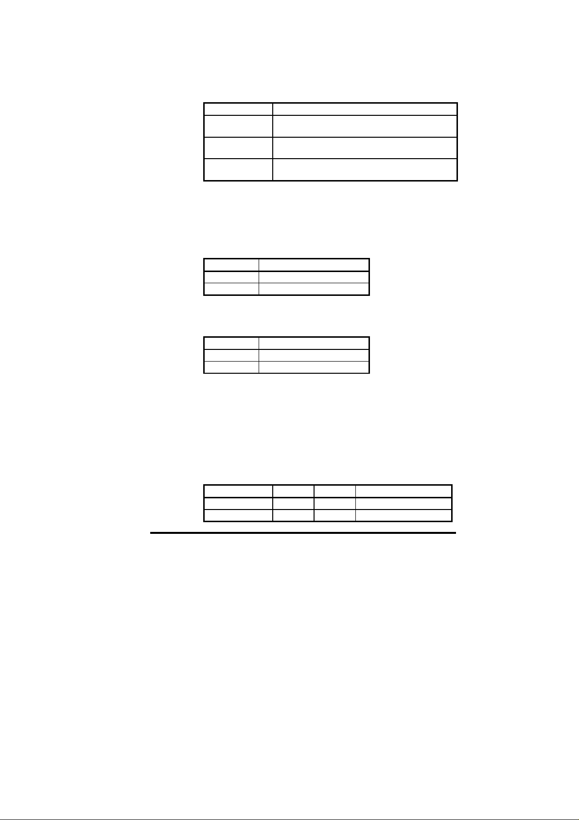
9.13.1 MotorType
Class: 42 (0x2A) Instance: 1 (0x1) Attribute: 3 (0x3)
Defines the type of motor Unidrive supports in different modes of
operation.
DriveMode Motor Types Supported
Open Loop 6 - Wound Rotor Induction Motor
Closed L oop 6 - Wound Rotor Induction M ot or
Servo 9 - Sinusoidal permanent magnet BL Motor
9.13.2 RatedCurrent
Class: 42 (0x2A) Instance: 1 (0x1) Attribute: 6 (0x6)
This attribute specifies or returns the rated current (in amps) for the
motor, to an accuracy of 1 decimal place. On size 1 and 2 Unidri ve, the
second dec imal place of current is not access ible via DeviceN et. On
size 5 Unidri ve, the dec imal plac e is not avail abl e insi de the dri ve, but it
must be specified over DeviceNet.
Action Mapping
Read #5.07
Write #5.07
9.13.3 RatedVoltage
Class: 42 (0x2A) Instance: 1 (0x1) Attribute: 7 (0x7)
This attribute spec ifies the rated voltage for the motor.
Action Mapping
Read #5.09
Write #5.09
7 - Squirrel Cage Induction Motor
7 - Squi rrel Cage Induction Motor
10 - Trapez oi d al p er m an ent m agnet BL Motor
9.14 Control Techniques Object
Class: 100 (0x64)
This application specific object provides a means to access all
parameters within a Control Techniques Drive. Each of the drive
menus is mod elled as an instanc e within this objec t; each par amet er is
an attribute of that in stance.
When using an explicit connection, each drive parameter should be
access ed as a 16-bit int eger, except for menus 70 to 73 on Unidrive.
These UD7 0 internal par amet ers are 32-bi t signed par amet ers, and will
accept or ret urn 4 b yte (32 bit) dat a val ues.
Service Code Class Instance Service Name
16 (0x10) No Yes S et_Att r ibute_Single
14 (0x0E) Yes Yes Get_Attribute_Single
Issue Number: 2 51
Page 52
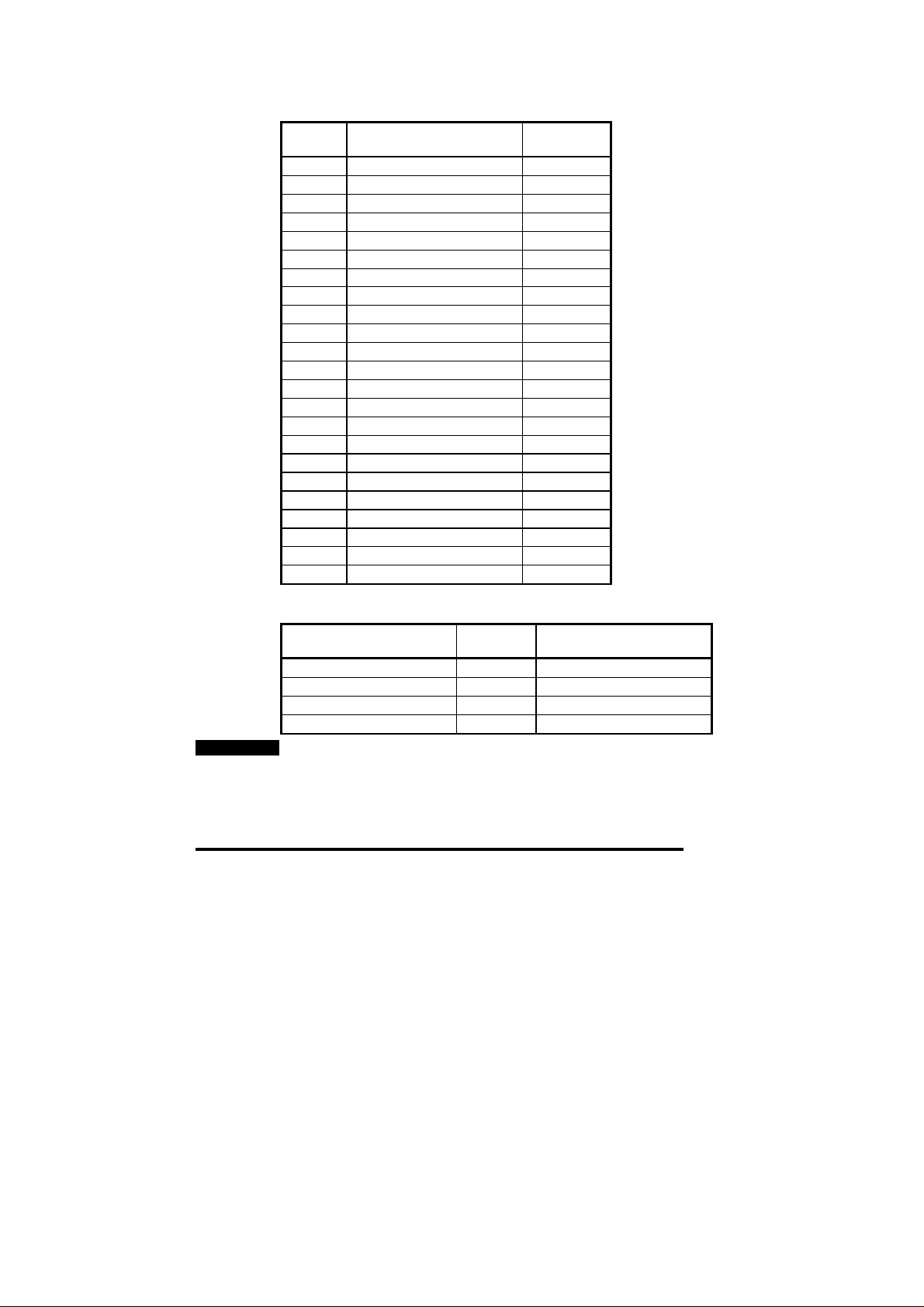
NOTE
The tabl e bel ow indic ates t he num ber of inst ances s upport ed an d als o
the number of attributes within each instance.
Instance Menu Number of
1 Speed Reference 50
2 Speed Ramps 41
3 Speed Control 30
4 Current Control 20
5 Motor Control 33
6 Sequencing 38
7 Analogue I/O 32
8 Digital I/O 28
9 Logic 33
10 Drive Status 42
11 Drive Set-up 35
12 Programmable Thresholds 17
13 Position Control 19
14 Process PID Loop 18
16 Small Option Module 41
17 Large Option Module Set-up 28
18 User Menu 1 50
19 User Menu 2 50
20 Large Option Module 50
70 Application Menu 100
71 Application Menu 100
72 Application Menu 100
73 Application Menu 100
If an attempt to access a drive parameter using this object fails, the
codes in the table below will indicate the reason for the failure.
DeviceNet Error Message DeviceNet
Error Code
Attribute not supported 0x14 Parameter does not exist.
Attribu t e not s et t abl e 0x0E Paramet er is r ead only.
Attribu t e not s et t abl e 0x0E Paramet er is wr it e onl y.
Invalid attr i bute value 0x09 Paramet er valu e out of r ang e.
Since V2.00.00 firmware was released, new parameters have been
added to some menus in the Unidrive. It is not possible access these
paramet ers via th e Devi ce Net interface.
Attributes
Reason
52 Issue Number: 2
Page 53

10 Quick Reference
10.1 Complete Parameter Reference
Parameter Default Description
#20.01 121 OU T Ch ann el 2 M app in g
#20.02 408 OU T Ch ann el 3 M app in g
#20.03 201 IN Channel 2 Mapping
#20.04 402 IN Channel 3 Mapping
#20.05 0 Node Address
#20.06 9011 OUT Ch ann el 1 M app in g
#20.07 9011 IN Channel 1 Mapping
#20.08 0 Data Rate
#20.09 0 Node Status (Read only)
#20.10 0 Network Status (Read only)
#20.11 48 Trip Delay Time (ms)
#20.12 0 Product Code Elaboration
#20.14 ---- Option ID Code (Read only)
#20.15 ---- Firmware Version XXYY, where the firmware
#20.50 ---- Fieldbus Diagnostic (Read only)
#17.02 ---- System File Version (R ead only)
#17.14 0 Network Loss Trip Enable
#17.19 0 UD70 Store and R eset
#20.13 0 Reserved
#20.16 0 Reserved
#20.17 0 Reserved
#20.18 0 Reserved
#20.19 0 Reserved
#20.20 0 Reserved
version is VXX. YY.ZZ (Read only)
10.2 DeviceNet Data Format
The Unidrive Devic eNet interface has a data format of 3 polled data
words. Explicit data must be used for non-cyclic communications.
Non-cyclic
mode
Explicit 3 This is the same data format as Mentor II,
Issue Number: 2 53
Polled
words
Comments
and Form at 0.03 on Com m an d er SE
Page 54

10.3 Fieldbus Control Word
b15 b14 b13 B12 b11 b10 b9 b8
M6 M5 #18.33 M3 M2 M1 M0 #18.32
b7 b6 b5 b4 b3 b2 b1 b0
#18.31 #1.46 #1.45 TRIP RUN
Bit Function Description
0 ENABLE Set to 1 to put the Unidrive in READY mode. (The
1 RUN
FWD
2 JOG Set to 1 with RUN FWD or RUN REV bit also set to
3 RUN
REV
4 TRIP Set to 1 to trip the Unidrive on “tr52”. The TRIP bit
5 #1.45
6 #1.46
7 #18.31 User application bit
8 #18.32 User application bit
9 M0 ENABLE mask bit
10 M1 RUN FWD mask bit
11 M2 JOG mask bit
12 M3 RUN REV mask bit
13 #18.33 User application bit
14 M5
15 M6
hardware ENABLE must also be present.) The RUN
FWD, JOG and RUN REV bits will have no effect
unless the ENABLE bit is set to 1. The Unidrive
outputs are disabled i mmediatel y wh en th e EN AB L E
bit is reset to 0, and the motor will coast to stop
Set to 1 to run the motor in the forwards direction.
Reset to 0 to dece lerate the motor to a controlled
stop before the Unidrive output stage is disabled
jog th e mot or i n th e appropriate direction. The
Unidri ve will ramp the m otor to the normal speed or
stop when the JOG bit is reset to 0, depending on
the status of the RUN FWD and RUN REV bits.
Set to 1 to run the motor in the reverse direction.
When res et to 0, the Unid r i ve wil l decelera te the
motor to stop before the outputs are disabled
must be reset to 0 before the Unidrive can be reset.
Preset Reference Select. These bits are used to
sele ct the digital s pee d re ferences used. Refer to
the Unidrive User Guide for more information.
Mask bits for the Preset Reference Select bits
REV
JOG RUN
FWD
ENABLE
54 Issue Number: 2
Page 55

10.4 Fieldbus Status Word
b15 b14 b13 b12 b11 b10 b9 b8
X #10.15 #10.14 #10.13 #10.12 #10.11 #10.10 #10.09
b7 b6 b5 b4 b3 b2 b1 b0
#10.08 #10.07 #10.06 #10.05 #10.04 #10.03 #10.02 #10.01
Bit Parameter Description
0 #10.01 Drive healthy
1 #10.02 Drive running
2 #10.03 Zero speed
3 #10.04 Running at or below min speed
4 #10.05 Below set speed
5 #10.06 At speed
6 #10.07 Above set speed
7 #10.08 Load reached
8 #10.09 In current limit
9 #10.10 Regenerating
10 #10.11 Dynamic brake active
11 #10.12 Dynamic brake alarm
12 #10.13 Direction commanded
13 #10.14 Direction running
14 #10.15 Mains Loss
15 X Not used
Issue Number: 2 55
Page 56

10.5 Unidrive Trip Codes
The trip codes listed below may be caused by the Unidrive DeviceNet
interf ace. Other tri ps may occur if a DPL prog ram is load ed. For a full
list of UD70 trips, refer to the UD70 User Guide
Trip
Error
Code
tr52 This code indi cates that the trip or ig in at ed from th e setting o f
bit 4 in the control Word
tr56 The UD70 does not contain the correct operating system for
the detected hard ware. Download the syst em file
“IBSPROFI.SYS”. If the trip persists, ensure that the UD73A
and UD70 b oar ds inside the mod ule are prop erl y cl ip p ed
togeth er . (This s hould only b e attempted b y suit ab ly qualifi ed
personnel!!)
tr57 An illegal operating system call has been made, e.g. WRNET.
CTNet comman ds c annot be used with DeviceNet
tr60 Bus Off. This is a l ow-level CAN trip condit ion, and prev ents
the node from communicating with the network. A manual
reset is required to clear the Bus Off condition
tr62 This tr ip indic at es th at loss of the DeviceN et n etwork h as b een
detected. This can be caused by disconnecting the node from
the network, a bad cable connection, or by resetting or
stoppin g th e network m ast er c ontroller
56 Issue Number: 2
 Loading...