

Page 1

User Guide
UD70UD70
Large Option Module and
software for Unidrive
Part Number: 0447-0017
Issue Number: 2
Page 2

Safety Information
Persons supervising and performing the electrical installation or maintenance of a Drive
and/or an external Option Unit must be suitably qualified and competent in these duties.
They should be given the opportunity to study and if necessary to discuss this User Guide
before work is started.
The voltages present in the Drive and external Option Units are capable of inflicting a
severe electric shock and may be lethal. The Stop function of the Drive does not remove
dangerous voltages from the terminals of the Drive and external Option Unit. Mains
supplies should be removed before any servicing work is performed.
The installation instructions should be adhered to. Any questions or doubt should be
referred to the supplier of the equipment. It is the responsibility of the owner or user to
ensure that the installation of the Drive and external Option Unit, and the way in which
they are operated and maintained complies with the requirements of the Health and Safety
at Work Act in the United Kingdom and applicable legislation and regulations and codes of
practice in the UK or elsewhere.
The Drive software may incorporate an optional Auto-start facility. In order to prevent
the risk of injury to personnel working on or near the motor or its driven equipment and to
prevent potential damage to equipment, users and operators, all necessary precautions
must be taken if operating the Drive in this mode.
The Stop and Start inputs of the Drive should not be relied upon to ensure safety of
personnel. If a safety hazard could exist from unexpected starting of the Drive, an
interlock should be installed to prevent the motor being inadvertently started.
General information
The manufacturer accepts no liability for any consequences resulting from inappropriate,
negligent or incorrect installation or adjustment of the optional operating parameters of
the equipment or from mismatching the variable speed drive (Drive) with the motor.
The contents of this User Guide are believed to be correct at the time of printing. In the
interests of a commitment to a policy of continuous development and improvement, the
manufacturer reserves the right to change the specification of the product or its
performance, or the contents of the User Guide, without notice.
All rights reserved. No parts of this User Guide may be reproduced or transmitted in any
form or by any means, electrical or mechanical including photocopying, recording or by
any information-storage or retrieval system, without permission in writing from the
publisher.
Copyright © November 1997 Control Techniques Drives Ltd
Author: CT SSPD
Originators AH, PB
Issue Code: 70nu2
Issue Date: November 1997
S/W Version: V2.6.0 system files and later.
Page 3

Contents
1 Introduction 1-1
1.1 Overview 1-1
1.2 Memory 1-2
1.3 PC requirements 1-2
1.4 Technical data for the UD70 1-2
1.5 User knowledge 1-2
2 Installation 2-1
2.1 Installation procedure 2-1
2.2 Configuring the system 2-2
3 Getting Started 3-1
3.1 Introduction 3-1
3.2 Example DPL program 3-1
3.3 Creating a DPL file using the DPL Toolkit 3-4
4 DPL Programming 4-1
4.1 Program headers 4-1
4.2 Comments 4-2
4.3 Variables 4-3
4.4 Parameters 4-5
4.5 Operators 4-5
4.6 Tasks and real-time programming 4-7
4.7 Instructions and functions 4-14
4.8 Optimizing programs 4-16
4.9 Parameter pointers 4-18
4.10 Defining aliases (constants) 4-18
Page 4

5 DPL Toolkit 5-1
5.1 Overview of the DPL Toolkit 5-1
5.2 File management 5-2
5.3 Editing a program 5-6
5.4 Applying styles 5-8
5.5 Compiling and running a program 5-9
5.6 Downloading a program 5-11
5.7 Running a program 5-12
5.8 Program monitoring and debugging facilities 5-12
6 Serial Communications 6-1
6.1 Introduction 6-1
6.2 Hardware connections 6-2
6.3 ANSI communications 6-4
6.4 Serial communications modes 6-12
6.5 ANSI instructions 6-15
6.6 Example ANSI instructions 6-16
7 Reference 7-1
7.1 Tasks 7-1
7.2 Instructions and functions 7-5
Page 5

8 Features 8-1
8.1 PLC parameters 8-1
8.2 Introduction 8-2
8.3 Encoder lines 8-3
8.4 Position 8-4
8.5 Enabling the position controller 8-5
8.6 Default and Reset Values 8-6
8.7 Parameter Descriptions 8-7
8.8 Logic Diagrams 8-20
8.9 Digital Lock 8-25
8.10 Cam function 8-27
8.11 Reference Switching 8-30
8.12 Timer/Counter unit 8-32
8.13 Digital I/O ports 8-36
8.14 Non-volatile memory storage 8-37
8.15 Using the RS232 port for Drive to Drive
communications 8-37
9 Diagnostics 9-1
9.1 Run-time errors 9-1
9.2 Run-time trip codes 9-2
9.3 Compiler error messages 9-3
9.4 Advanced error-handling 9-5
10 Parameters 10-1
10.1 UD70 set-up parameters 10-1
10.2 Virtual parameters 10-4
10.3 RS485 port modes 10-11
10.4 General-purpose parameters 10-12
Page 6

Page 7

1 Introduction
On a Variable Speed Drive such as Unidrive, timing functions necessary for
the correct operation of power devices are performed by its own
microprocessor operating in real-time. This imposes limitations on the
microprocessor when carrying out other duties, resulting in a reduction of
flexibility of the Drive.
To maximize this flexibility, a second processor can be used for running
application-specific software. This second microprocessor is the
which allows the Drive to be easily adapted to applications by programming
software in the UD70.
1.1 Overview
The UD70 is a compact microcomputer contained in a Large Option Module
for easy installation in any size of Unidrive.
Together with the
software or use pre-written software in order to enhance the flexibility of a
Unidrive.
DPL Toolkit (Windows™ interface)
The DPL Toolkit is contained on two diskettes. It is a program which runs in
Microsoft® Windows™ Version 3.1x and Windows™ 95. Programs for the
UD70 are written on a host PC using the DPL Toolkit.
The
UD70 uses a high-level programming language called DPLDPL
(Drive Programming Language) which is in many respects similar to the
BASIC language. DPL is a compiled program which gives it the ability to run
at high speed.
The DPL Toolkit is used to write, compile and download a DPL program to an
UD70. The Toolkit also has a comprehensive set of de-bugging facilities to
aid the development and testing of the DPL program.
Connection between the
communications link. This link need only be used during program
development, testing and commissioning. It can be disconnected after the
software has been successfully loaded.
UD70
DPL Toolkit, the UD70 allows the programmer to write
UD70 and host PC is via an RS232 serial
UD70
Issue code: 70nu2
Introduction 1-1
Page 8
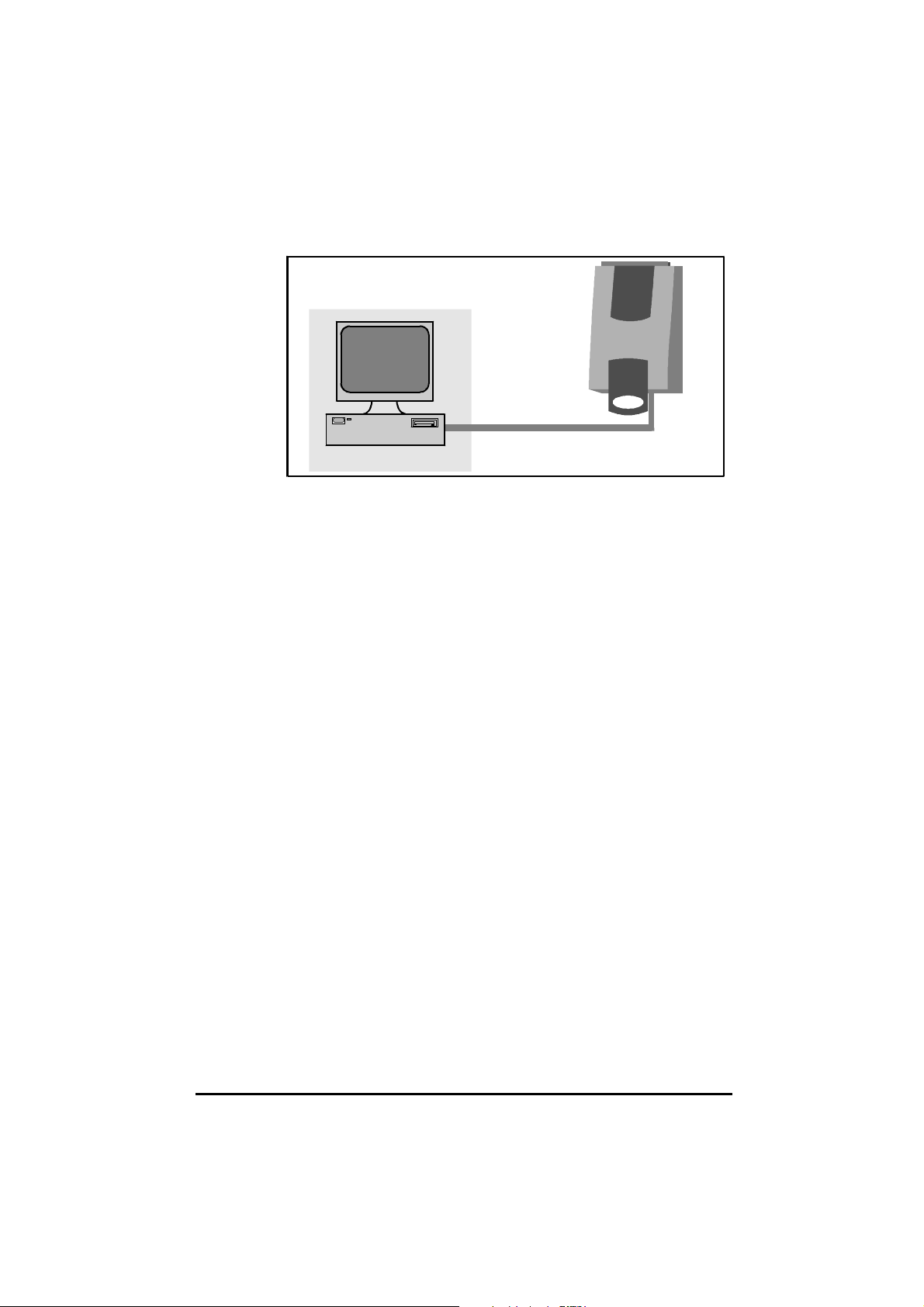
UD70 connected to a host computer by a serial link
1.2 Memory
The compiled UD70 program and the user-created source program are
stored in non-volatile EEPROM memory on the UD70 card. This type of
memory allows the programs to be loaded using the serial port.
Latest versions of programs can be easily updated without removing any
integrated circuits or without using any specialized programming equipment.
The filing system of the
UD70 at any one time.
The compiled program can be stored along with the DPL source code. This
allows the site engineer to read the program stored in the
program is not on the host PC. (This option can be disabled if it is not required.)
UD70 allows only one program to be stored in the
UD70, even if the
1.3 PC requirements
The minimumminimum requirement for the DPL Toolkit is as follows:
IBM AT compatible 386SX PC, Windows™ 3.1, 4Mb RAM, DOS5
PC with 8MB RAM is recommended
A 486
1.4 Technical data for the UD70
Intel 960 32-bit RISC processor
96kb of user program storage
8kb user
16MHz clock
RS232 port for programming (IBM AT compatible)
RS485 optically isolated port for permanent serial communications
RAM
1.5 User knowledge
This User Guide assumes that the user has at least superficial knowledge of
Microsoft® Windows™. Refer to the Windows User’s Guide for specific
information on performing operations in Windows™.
1-2 Introduction
Issue code: 70nu2
UD70
Page 9
2 Installation
The voltages present in the Drive are capable of
inflicting a severe electric shock and may be lethal. The
Stop function of the Drive does not remove dangerous
Warning
2.1 Installation procedure
voltages from the Drive or the driven machine.
AC supplies to the Drive must be disconnected at least
15 minutes before any cover is removed or servicing
work is performed.
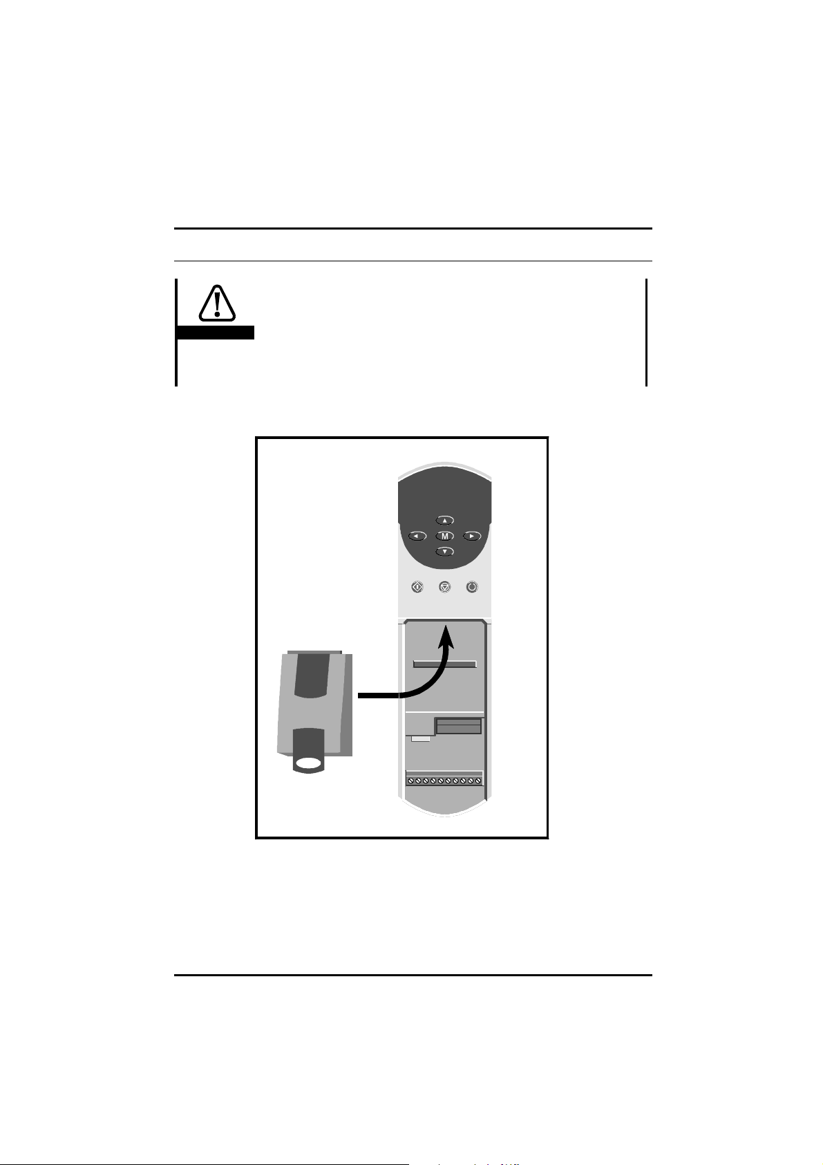
Location of the UD70 in the Unidrive
Refer to the Unidrive User Guide for instructions on fitting a large option
module to the Drive.
UD70
Issue code: 70nu2
Installation 2-1
Page 10
2.2 Configuring the system
Host PC connections
RS232 Port
RS232 serial port is a dedicated link to the host PC. The port is a 9-way
The
female D-type connector. Ready-made cables for RS232 serial
communications are generally available.
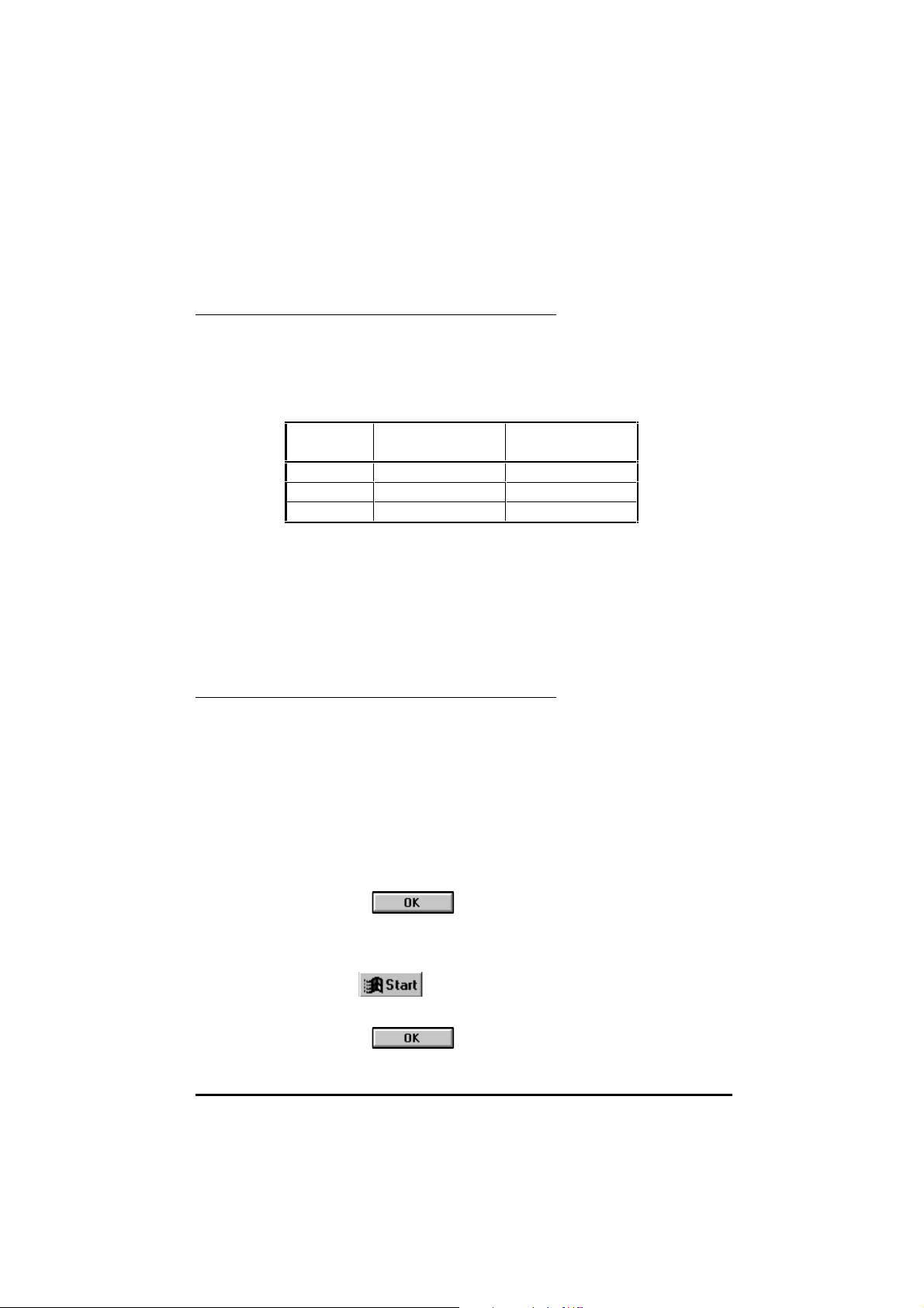
The table below gives the minimum required connections between the
and a 9-way and 25-way pin COM port connector.
UD70
pin no.
22 3
33 2
55 7
9-pin connector
pin no.
25-pin connector
pin no.
The RS232 port should be used only for commissioning because isolation or
protection of the port is not included.
Use the following instructions for connecting a host
1 Ensure no static charge has built up when the plug is inserted.
2 Using a maximum cable length of not more than 3 metres (10 feet),
connect an
RS232 cable to the RS232 serial port on the UD70 and to the
communications serial port of the host
PC:
PC.
Installing the DPL Toolkit in the host PC
Use either of the following procedures:
Windows 3.1
The DPL Toolkit requires a minimum of 4Mb of computer memory. This may be
virtual memory. Virtual memory may be set in the 386386 Enhanced Enhanced section of Windows
Control Panel.
1 Start Microsoft Windows
2 Insert disk 1 of the DPL Toolkit into the A: Drive of the host PC.
3 In Windows Program Manager, select FileFile on the menu bar. Select RunRun.
4 Type A:\SETUP.
RAM or
UD70
5 Click on
Windows 95
1 Insert disk 1 of the DPL Toolkit into the A:A: of the host PC.
2 In the menu, select RRun...un....
3 Type A: \SETUP .
4 Click on
2-2 Installation
Issue code: 70nu2
UD70
Page 11
Downloading the system file
The UD70 has no pre-loaded system software. The first task is to program
the system software using the DPL Toolkit. Use the following procedure:
1 Connect the serial communications cable to the UD70.
2 Apply AC power to the Drive.
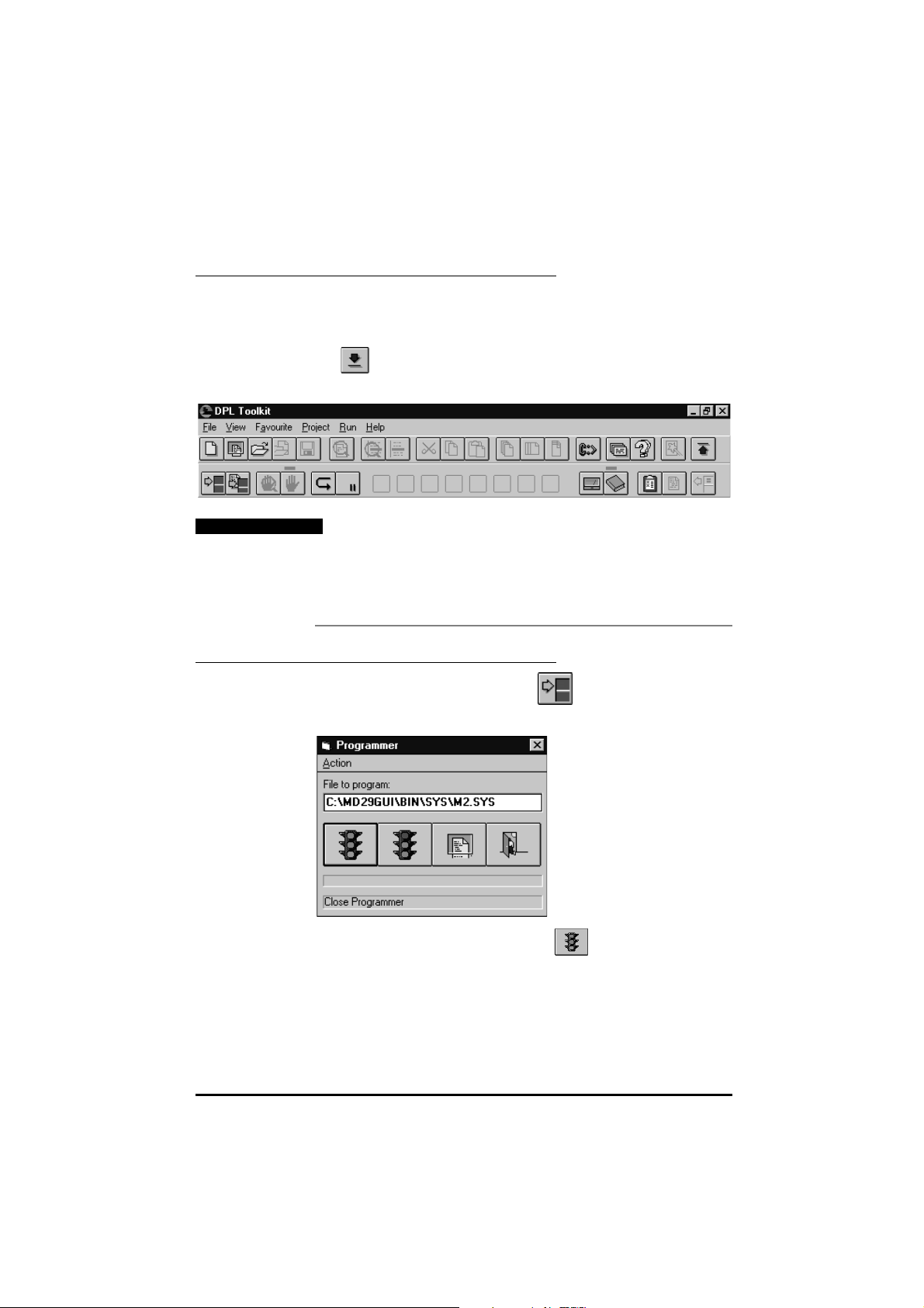
3 In Windows 3.xx Program Manager, or in the Windows 95 Start menu,
click on:
The DPLDPL Toolkit Toolkit window appears. At the top of the window are a
menu bar and toolbar.
4 If the serial port of the host PC is not COM1, open the ProjectsProjects menu
and select ConfigureConfigure. In the drop-down menu that appears, select
ComportComport. This opens a further drop-down menu which allows
selection of the required communications port.
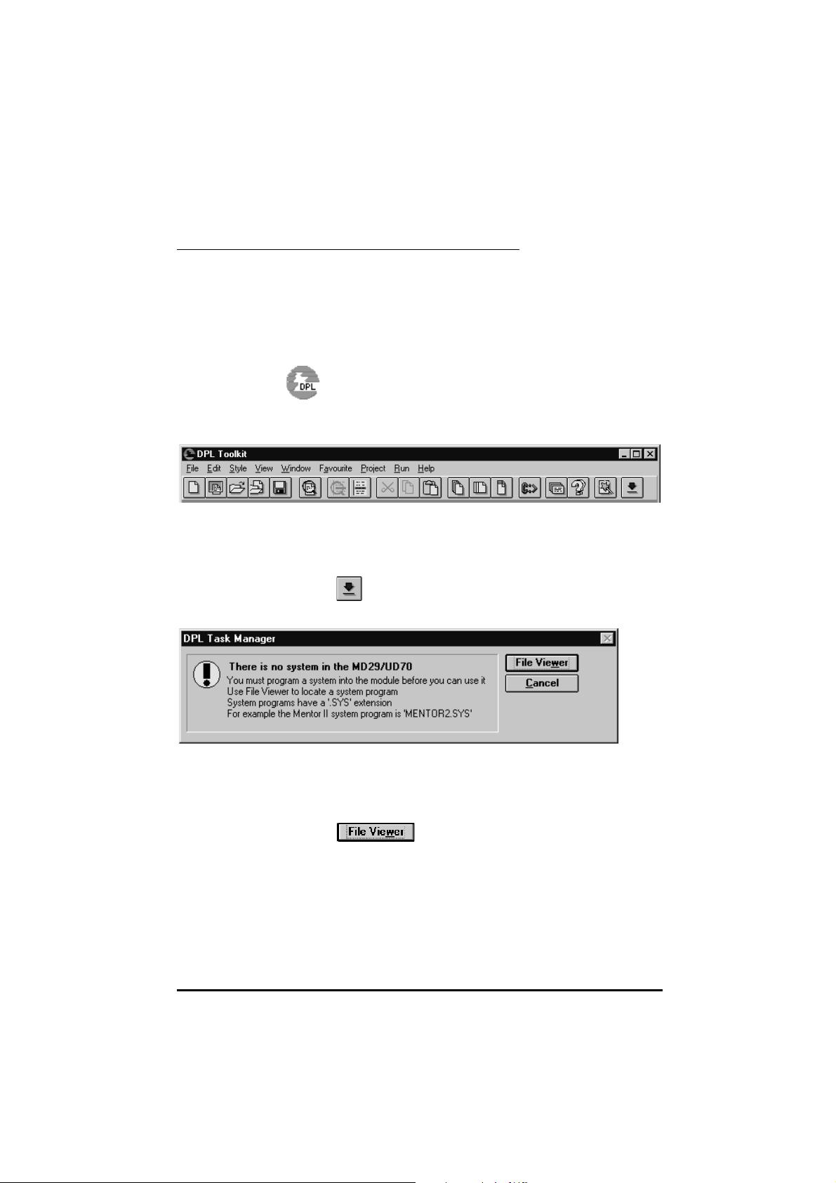
5 Click on (Open Task ManagerOpen Task Manager). After a few moments, the DPLDPL
Task ManagerTask Manager dialog box appears.
If the dialog box does not appear, and all the buttons in the lower
6 Click on . The File Viewer File Viewer dialog box appears.
UD70
Issue code: 70nu2
toolbar of the window appear shaded (inactive), communications
could not be established with the
correct, and the correct
COM port is used.
UD70. Check the connecting cable is
Installation 2-3
Page 12
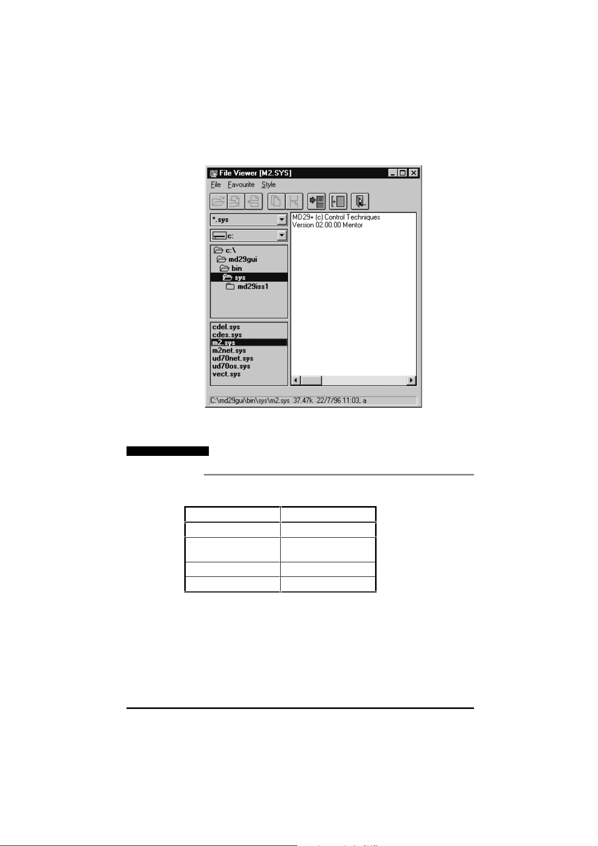
Note
In the panels on the left side of the dialog box the path and names of
.SYS files can be selected.
the
The system files are located in directory MD29GUI\BIN\SYS.
7 Select the correct path for the required system files. Double-click on
SYS file specified in the following table:
the .
Drive File
UD70 UD70OS.SYS
UD70 with Interbus S or
Profibus DP
UD70 with ModBus Plus MBPLUS.SYS
UD70 with CTNet UD70NET.SYS
IBSPROFI.SYS
The ProgrammerProgrammer dialog box appears.
2-4 Installation
Issue code: 70nu2
UD70
Page 13
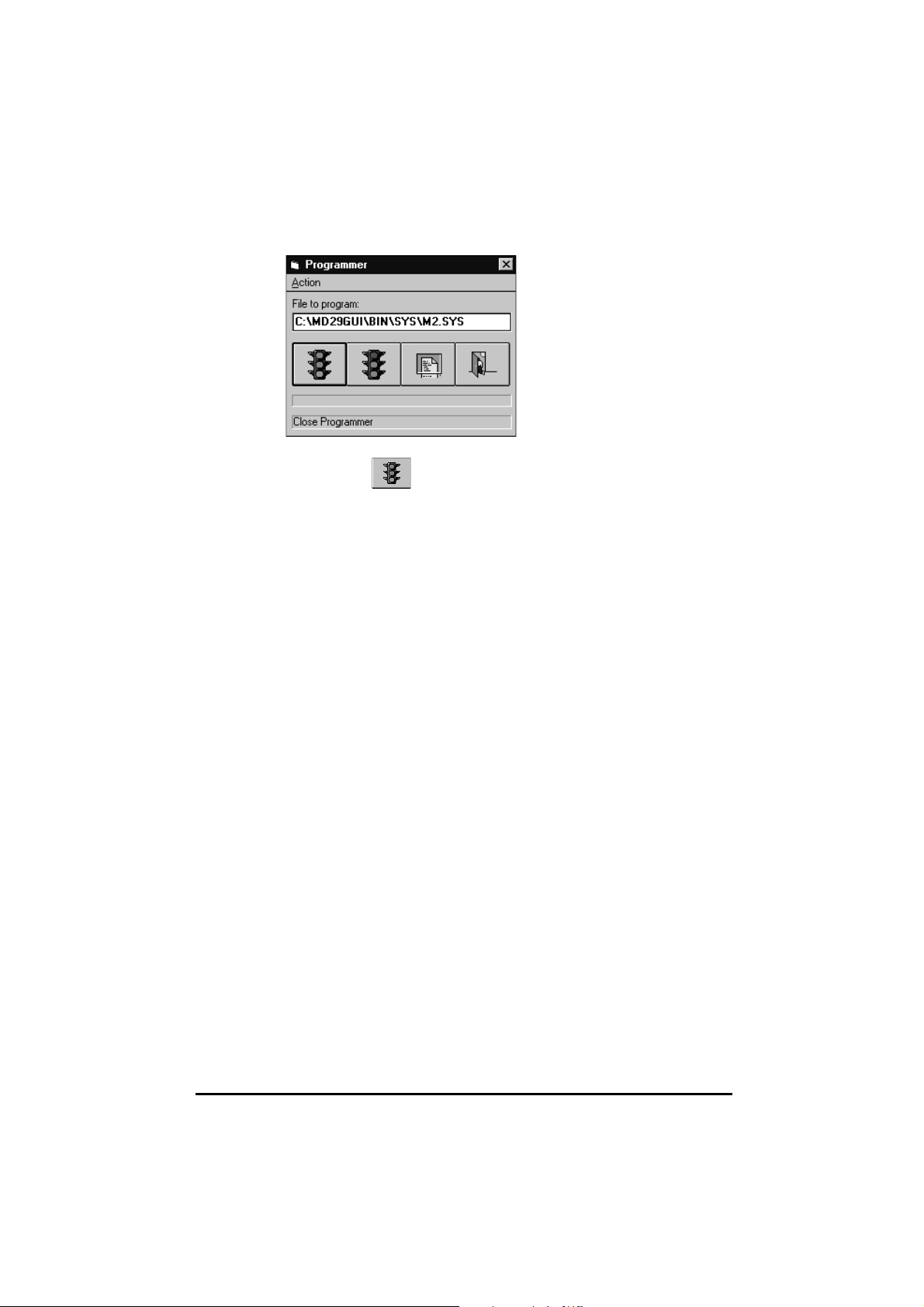
8 Click on (green light showing). The system file is now loaded
into the
UD70.
UD70
Issue code: 70nu2
Installation 2-5
Page 14

2-6 Installation
Issue code: 70nu2
UD70
Page 15

3 Getting Started
3.1 Introduction
This chapter explains the key elements of DPL programming, and the
methods used to create, compile and run an example program using the DPL
Toolkit.
An example of a short
of the program instructions.
Note that parameter numbers are denoted in this User Guide and in
DPL programs by # (eg. parameter 1.21 is denoted as #1.21).
3.2 Example DPL program
The DPL program described here is called SawtoothSawtooth, because it applies a
repetitive cycle consisting of a linear increase in speed demand followed by
an instantaneous reduction to zero, as shown in the following diagram.
Repetitve cycle produced by the Sawtooth program
DPL program is given below, followed by explanations
UD70
Issue code: 70nu2
Getting started 3-1
Page 16
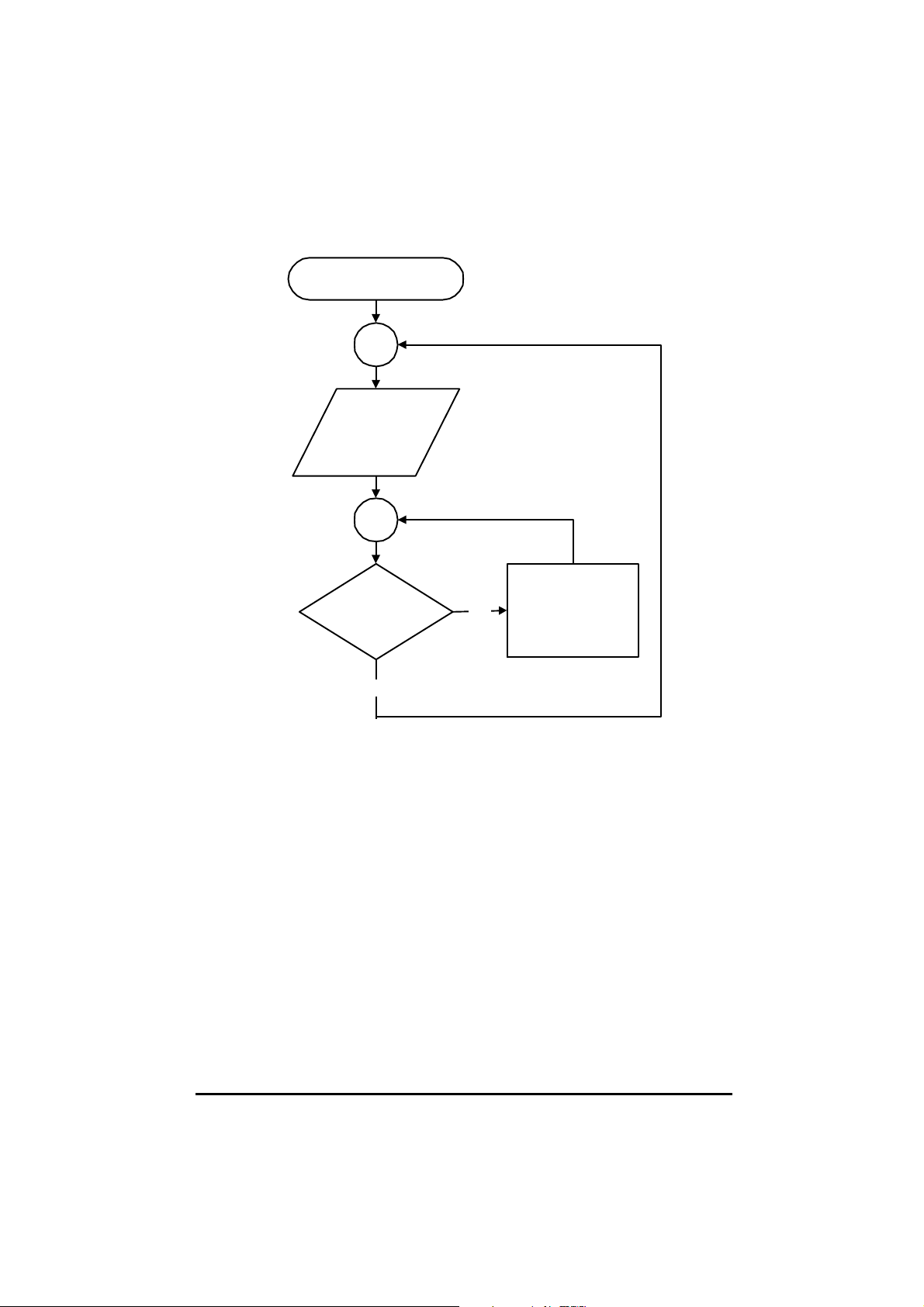
Start
#1.21 = 0
Is #1.21 < 1000?
No
Flow diagram of program Sawtooth
Program instructions
$TITLE Sawtooth
$VERSION 1.1.1
$DRIVE Unidrive
$AUTHO R MyName
$COMPA NY MyCo
//Note: T his is a c o m me nt.
BACKGROUND{
Top:
#1.21=0
DO WHILE #1.21<1000
#1.21=#1.21+1
LOOP
GOTO
Top:
}
Yes
#1.21=#1.21+1
3-2 Getting started
Issue code: 70nu2
UD70
Page 17

Explanation of the example program
$TITLE Sawtooth
The first line of a program must be
can have a maximum of 64 characters.
$VERSION 1.1.1
The second line is
of eight characters. The recommended format is $VERSI ON 1.0.0.
Updates are easily shown by increasing the last number, eg. 1.0.11.0.1.
Major modifications are shown by 2.0.02.0.0, 3.00 3.00, etc.
$DRIVE Unidrive
The third line is
it is installed in. (Since the DPL Toolkit can be used with the UD70 and
the MD29, this must be stated.)
$AUTHOR MyName
$COMPANY MyCo
The fourth and fifth lines are used to define the author of the program
and the company name.
Note
Unless these lines are included, the program will not be
compiled.
//Note: This is a comment.
The program ignores comment lines which can be placed anywhere in a
program. Comments are always preceded by either a double forward
slash [////] or a semi colon[;].
Comments are useful for inserting descriptions, or for giving
explanations for the benefit of the user or programmer.
BACKGROUND{
BACKGROUND is a type of Task. (All executable code must be
contained within a Task.) There are many different types of Task,
which, in effect, define the priority of the code and allow blocks of
code to be run on different time-bases.
BACKGROU ND task is a free-running task which can be compared to
The
the way a PLC runs a program, for example. Full details of the Tasks are
given in Real-time programming in Chapter 4 DPL Programming.
Top:
Top:Top: is a label which marks an absolute position in the program. A label
must always be followed by a colon [::].
A label defines the destination of a
any name (eg. mylabelmylabel).
#1.21=0
A hash (##) expression accesses Drive parameters. In this case the
parameter is 1.21 (menu 1, parameter 21). This is a preset speed
reference parameter in the Unidrive, and it is set at zero.
$TITLE program name. The name
$VERSIO N number. The number can have a maximum
$DRIVE drive name. This tells the compiler which Drive
GOTO statement. It can be given
UD70
Issue code: 70nu2
Getting started 3-3
Page 18

Note
DO WHILE #1.21<1000
DO WHILE is a loop statement. In this example, it gives the program an
instruction to repeat the following block of code while the value of
parameter 1.21 is less than 1000.
#1.21=#1.21+1
This line adds the value 11 to parameter 1.21. Every time this command is
executed, 11 is added to the parameter value.
LOOP
LOOP is the end expression for the Instruction DO WHILE. LOOP tells
the program to go back to the line DO WHILE and check that the DO
instruction remains true. When the value of #1.21 = 1000#1.21 = 1000, DO
WHILE
#1.21 < 1000 #1.21 < 1000 becomes false. The instructions between DO
WHILE
and LOOP stop being repeated and the program goes to the
WHILE
next line after the LOOP command.
GOTO Top:
GOTO is a flow-control instruction. In this case, it tells the program to
go to the label Top:Top:. This causes the program to run continuously.
The label name must be specified using a colon[:].
} Closing brace
Instructions within braces belong to the defined Task. Closing-braces
work in conjunction with opening-braces. In this example, the
opening- and closing-braces work in conjunction with the Task
BACKGROUND..
3.3 Creating a DPL file using the DPL Toolkit
This section shows how to write, compile and download the example
DPL program for the Unidrive.
Opening the DPL Toolkit
In Windows 3.xx Program Manager, or Windows 95 Start menu, click on:
The DPLDPL Toolkit Toolkit window appears. At the top of the window are a menu bar
and toolbar.
3-4 Getting started
Issue code: 70nu2
UD70
Page 19
Creating a file
1 Click on or open the File File menu and select NewNew.
2 Enter the following program exactly as it appears, using the tab key to
indent lines.
$TITLE Sawtooth
$VERSION 1.1.1
$DRIVE Unidrive
$AUTHO R MyName
$COMPA NY MyCo
//Note: T his is a c o m me nt.
BACKGROUND{
Top:
#1.21=0
DO WHILE #1.21<1000
#1.21=#1.21+1
LOOP
GOTO
Top:
}
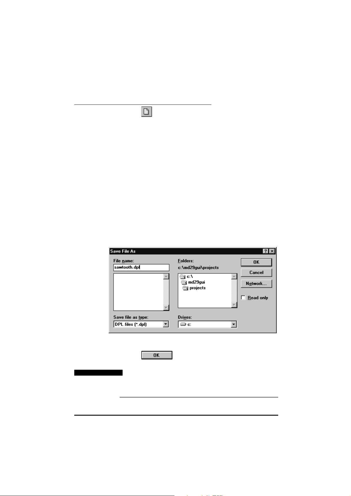
3 Open the FileFile menu and select Save As...Save As.... The Save File AsSave File As dialog box
appears.
4 In the Folders: Folders: list, select the ProjectsProjects directory. In the FileFile name: name:
5 Click on . The file is now saved.
The program is ready for compiling into machine code.
Important Note
UD70
Issue code: 70nu2
text box, type
DPL programs must be saved as .DPL files. If this is not
SAWTOOTH.DPL.
done, the program cannot be compiled into machine code.
Only the saved version of the program is compiled.
Getting started 3-5
Page 20
Compiling the program
The DPL Toolkit contains a compiler which converts DPL programs from text
format to binary machine code which the UD70 can understand. The
compiler converts the .DPL file into a binary file with a .BIN extension.
Use the following procedure.
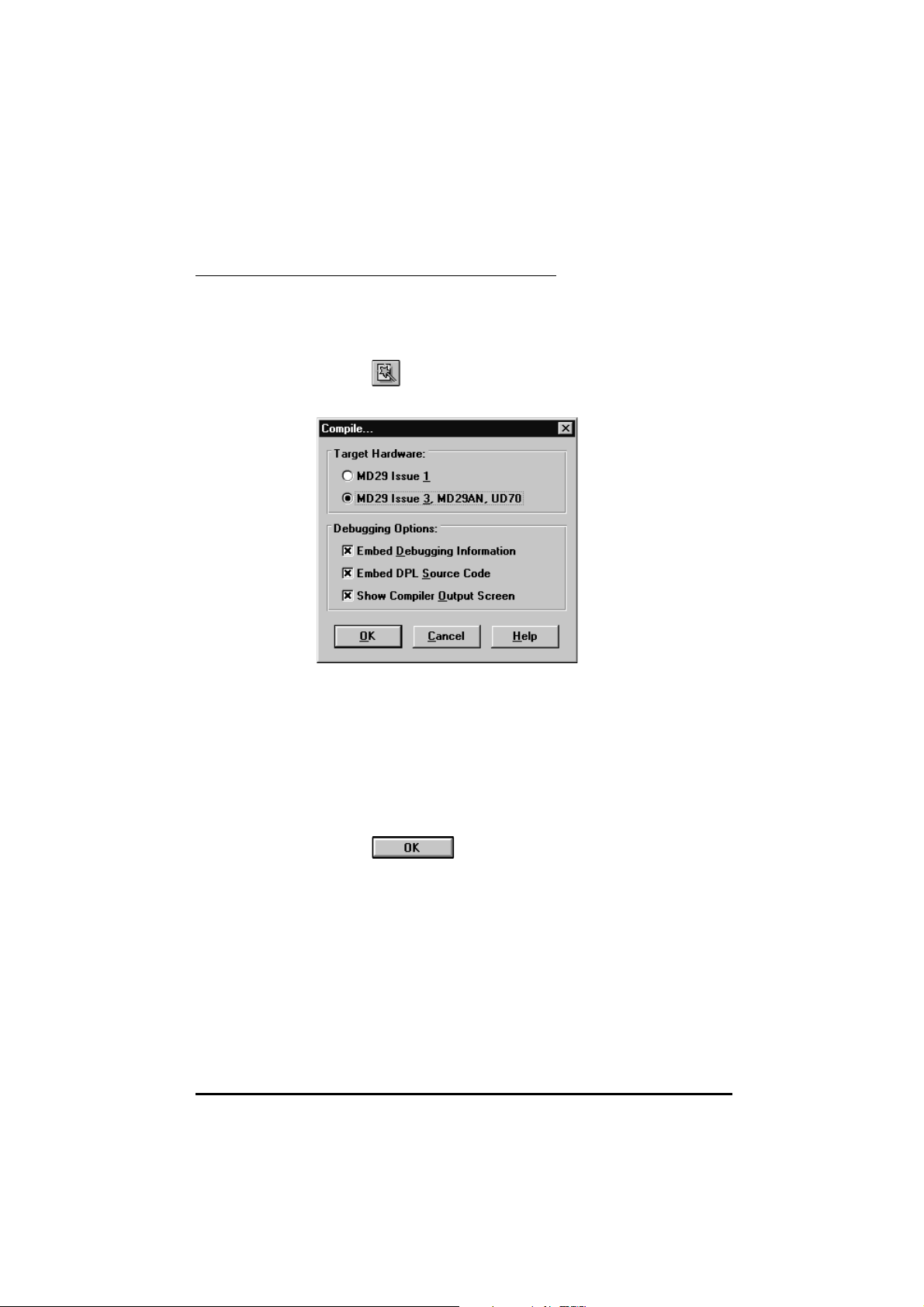
1 Click on at the right of the Toolbar. The Compile...Compile... dialog box
appears.
2 If the DPL source file is required to be downloaded to the UD70, ensure
the Embed DPL Source CodeEmbed DPL Source Code check box is checked. This facility
allows the DPL program to be read back to the
computer copy becomes lost, for example).
If the DPL source file is not to be downloaded, ensure the check box is
unchecked. When the Compile...Compile... dialog box next appears, the check
box retains the last setting.
(The other options in this dialog box are described in Compiling and
running programs in Chapter 5 DPL Toolkit.)
PC at a later date (if the
3 Click on
4 The CompilationCompilation box appears for a few seconds. It is not necessary to
observe the contents of the CompilationCompilation box.
5 The program is now compiled, ready for downloading to the UD70.
If instead a Build errorsBuild errors window appears with errors displayed, correct
the program for typing mistakes and repeat the compilation. (Error
messages are described in Chapter 9, Diagnostics.)
3-6 Getting started
Issue code: 70nu2
UD70
Page 21
Connecting to the UD70
It is now necessary to establish communications from the host PC to the
UD70 in order to download the compiled file.
Use the following procedure:
Click on
appearing below the standard toolbar.
Note
If all the buttons on the lower toolbar appear shaded, it is
an indication that communications could not be
established with the UD70. Check that AC power is applied
to the Drive, and that the serial communications cable is
correctly inserted.
Downloading the program
1 In the Task Manager toolbar, click on . The ProgrammerProgrammer dialog
box appears.
. The Task Manager opens with the Task Manager toolbar
2 In the ProgrammerProgrammer dialog box, click on (green light showing).
UD70
Issue code: 70nu2
The files
the
SAWTOOTH..BIN and SAWTOOTH..DPL are now downloaded to
UD70. Down-loading takes a few seconds to complete.
Getting started 3-7
Page 22

Note
Running the program
The Sawtooth program rapidly alters the speed
reference parameter of the Drive. For safety, ensure
the Drive is disabled before running the program.
Warning
In the Task Manager toolbar, click on
The Speed referenceSpeed reference parameter #1.21 #1.21 in the Drive will change value.
The UD70 can hold only one compiled program (ie. .BIN file)
in memory at one time. A program that is downloaded to
the UD70 will over-write an existing program.
Note that the ramping-up behavior cannot be observed since the
program alters the parameter value at a faster rate than the display is
updated.
3-8 Getting started
Issue code: 70nu2
UD70
Page 23

4 DPL Programming
This chapter explains the following parts of a DPL program:
• Program headers
• Comments
• Variables
• Parameters
• Tasks
• User-defined sub-routines
• Instructions
The explanation is followed by a section on optimizing
4.1 Program headers
A DPL program must begin with five program headers in the correct order,
as follows:
• Program title
• Program version
• Drive name
• Author name
• Company name
Each program header must be contained on a single instruction line in
the program.
Program title
DPL programs.
Syntax
$TITLE Program title
The
Maximum length: 64 characters
Program version
Syntax
UD70
Issue code: 70nu2
$VERSION
The $VERSION VersionVersion NumberNumber is for use by the programmer. It is
recommended that the format of the version number should be as follows:
Minor updates can be shown by increasing the last digit, eg. 1.0.21.0.2. Major
modifications can be shown by increasing the first digit, eg. 2.0.02.0.0.
Maximum length: 8 characters
$TITLE ProgramProgram titletitle is for use by the programmer.
$TITLE Sawtooth generator Sawtooth generator
eg.
Version Number
$VERSIO N 1.0.1 1.0.1
DPL programming 4-1
Page 24

Drive name
Syntax
$DRIVE
The type of Drive must be specified in $DRIVE DriveDrive namename since the DPL
Toolkit can be used with different types of Drive.
This program header ensures that the program is correctly compiled for the
option module and Drive.
Note
If a different Drive is specified, the program may not be
compiled, or run-time error 53 will occur when the
program is downloaded to the UD70.
Author name
Syntax
$AUTHOR
The $AUTHOR
Maximum length: 64 characters
Company name
Syntax
$COMPANY
The $COMPANY
Maximum length: 64 characters
Example program headers
Drive name
Author name
Author name
Company name
Company name
is for use by the programmer.
is for use by the programmer.
$TITLE Sawtooth
$VERSION 1 .0 .1
Unidrive
$DRIVE
$AUTHOR A.H.
$COMPANY
Control Techniques
4.2 Comments
Comments are purely for information and explanation purposes. They act in
the same way as REM commands by not acting on the program.
Comments begin with a double forward slash [//] or a semi-colon [;]. They
can be placed on their own line, or at the end of instruction lines. A
Comment ends at the end of the line.
Example
//This line contains a comment, which ends with the line.
//If the comment fl ows onto the next line, double forward
//slashes must be used to start the n ext lin e.
4-2 DPL programming
Issue code: 70nu2
UD70
Page 25

4.3 Variables
Basic variables
There are two basic types of variable, as follows:
• Integer variable (
• Floating-point variable (
INT)
FLOAT)
Integer
variables
Floatingpoint
variables
Integer variables are denoted by placing a % % symbol after the name of the
variable, and are internally represented by a two’s complement
32-bit number. This gives a decimal range of ±2147483647.
Floating-point variables have no symbol. These variables are
IEEE double-precision (64-bit) numbers which give a range of approximately
±1.7976 x 10
Accessing the variables
All variables are global within a program (ie. they can be accessed and
altered by any task). (There are no local variables.)
Bit-addressing of variables
All integer variables and arrays (see below) may be bit-addressed. This
means that each individual binary bit in the variable may be separately read
or written to. Bit-addressing is achieved by appending .n.n to the end of the
variable name, where nn is the bit number to be accessed.
Example
flag s% .3 = 1 ;set bi t 3 to 1
IF flags%.5 = 1 T HE N ... ;check bi t 5
Naming conventions
The first character of a variable must be a letter. Subsequent characters
may include letters, numbers and the underscore (_) character. These may
be in any order.
Variable names are case sensitive (eg. the variable name speed%speed% is not the
same as SPEED%SPEED%).
308
±
.
Preferred use of variables
It is recommended that integer variables are used where possible.
Operations on integer variables perform much faster than for
floating-point variables.
UD70
Issue code: 70nu2
DPL programming 4-3
Page 26

Arrays
Arrays are collections of variables of the same type (integer or floating
point) under the same name. Note that only single-dimension arrays
are allowed.
Each element (individual component) of an array is, in effect, a separate
variable. An element is accessed by a program by specifying the array name,
then placing the element number in square brackets [ ][ ] after the array name
The two basic forms of arrays are as follows:
Dynamic
arrays
Example
Constant
arrays
Example
Dynamic arrays can be set up and changed by DPL programs. A dynamic
array must contain, integer variables or floating-point variables, but not
both types of variable.
A dynamic array must first be specified using the
the INITIAL task), and the number of elements specified in square brackets
after the variable name. Dynamic arrays are placed in the 8kB of volatile
memory in the UD70 which limits the maximum size of the array.
DIM myarray%[20] ;Integer array having 20 ele ments
DIM array2[30] ;Floating-point array having 30 ele me nts
The elements in an array are numbered as follows:
0 to [Number of elements] – 1
From the example of an integer array given above, the first element of
myarray%[]myarray%[] is as follows:
myarray%[0 ]
The last element is as follows:
myarray%[19]
Constant arrays contain fixed pre-defined values that cannot be changed
by the DPL program when the program is being run. The values of the
constant array are defined in the DPL program by using a special section
CONST. (This section is typed in exactly the same way as a task.)
called
Only integer values can be defined in a constant array.
The advantage of using a constant array is that the array is placed in the
96kB of memory space in the
limited only by the amount of available program space in the UD70, and not
by the size of the 8kB RAM. The program space is used to store the
compiled DPL program, constant array data, and (optionally) the
DPL file itself.
CONST c_array% {
100, 1500, 500, 0, –400, –1000
–400, –100, 0
}
This defines an array called c c_array%[]array%[], which containes nine elements.
Note that the value of each element can be separated by a comma or a
new line.
UD70 which allows the size of the array to be
DIM instruction (usually in
4-4 DPL programming
Issue code: 70nu2
UD70
Page 27

4.4 Parameters
There are two types of parameter, as follows:
• Drive parameters
• Virtual parameters
(See Chapter 10 Parameters.)
Parameters are denoted by a ## (hash) symbol and are accessed using an xx,yy
format, where xx represents the menu and yy represents the parameter in the
menu.
For example, parameter p7.05p7.05 is accessed by entering #07.05#07.05, and p18.01p18.01 is
accessed by entering #18.01#18.01. Leading zeroes in the parameter can be
omitted, eg. #7.5#7.5 is the same as #07.05#07.05.
Parameters can also be accessed indirectly using an integer variable to
denote the parameter number. See Parameter pointers later in this chapter
for details.
4.5 Operators
Operators perform mathematical or logical operations on values. The
following operators are supported in DPL programming.
Note
Certain operators work only with integer values
or variables.
Operators for floating-point and integer variables
+ Plus
– Minus
/ Divide
* Multiply
UD70
Issue code: 70nu2
DPL programming 4-5
Page 28

Operators for integer variables only
Example
Example
Example
& Logic AND AB Y
000
010
100
111
5 & 14 = 4
| Logic OR
Logic XOR AB Y
!Value
Bit invert
AB Y
000
01 1
101
111
000
01 1
101
110
This Operator inverts the least-significant bit, and converts all
other bits to zero.
Example
!(value, bit-field-size)
Bit-field invert
1001000 (binary) is converted to 0000011 (binary)
This Operator inverts the specified number of least significant
bits, and converts all other bits to zero. The bitbit-field-field-size-size
specifies the number of least-significant bits that are to be
converted.
Example
Result% = !(value%, 3)
100100100 (binary) is converted to 000011011 (binary).
%
Remainder
This Operator gives the remainder when an integer is divided
by another integer.
Example
5 % 2 = 1
8 % 3 = 2
5 | 14 = 15
5 & 14 = 11
4-6 DPL programming
Issue code: 70nu2
UD70
Page 29

4.6 Tasks and real-time programming
Real-time programming runs with reference to a clock to enable the user to
specify the actual times instructions are executed, not just the order in
which they are executed. When real-time programming, a task Structure
(or philosophy) has to be maintained.
UD70 programs contain sections called tasks, where a task enables a priority
to be given to a sub-routine. Seven levels of priority are defined by these
tasks in the following order:
INITIAL task
•
BACKGROU ND task
•
CLOCK task
•
ENCODER task
•
SPEED task
•
EVENT task
•
ERROR task
•
Each task is specified by its name in the program. The contents of each task
must be placed in braces { }{ }.
Example
INITIAL task
Example
CLOCK{
instru ct ions
}
The INITIAL task is used typically to initialize program variables and Drive
parameters in the DPL program. The task runs only when the UD70 is reset
or at the moment AC power is applied.
The
INITIAL task has total priority over all other tasks when running; the
other tasks are prevented from running. This is significant when the CLOCK,
or ENCODER tasks are to manipulate data which have initial values.
EVENT
INITIAL{
// This is the only place to reliably initia lize ‘timer’
time r% = 0
}
CLOCK{
//This task is set a t 5 ms
//The v alue of time r m u st b e initiali z ed be fore CL OC K i s ru n
time r% = ti m er% + 1
IF timer% > 200 THEN
//200, 5ms inte rvals = 1 second
PRINT “1 Second expired”
timer% = 0
ENDIF
}
UD70
Issue code: 70nu2
DPL programming 4-7
Page 30

BACKGROUND task
The BACKGROUND task is used for functions and commands that do not
require time-related or encoder-related monitoring. This task would be
used for the following:
The
recommended that the majority of the program is run in the BACKGRO UN D
Task.
Note
• Data logging
• Checking digital inputs
• Setting output status
BACKGROU ND task runs after the INITIAL task is completed. It is
The BACKGROUND task does not automatically loop.
Example
BACKGROUND{
RAMP:
#1.21 = 0
DO WHILE #1.21<1000
#1.21 = #1.21+1
LOOP
GOTO RAMP:
}
4-8 DPL programming
Issue code: 70nu2
UD70
Page 31

BACKGROUND Task giving way to the CLOCK Task
CLOCK Task
timing period
INITIAL
Task
CLOCK
Task
BACKGROUND
Task
BACKGROUND Task giving way to the CLOCK Task,
and th e CLOCK Task giving way to the ENCODER Task
ENCODER Task
timing period
INITIAL
Task
ENCODER
Task
CLOCK
Task
BACKGROUND
Task
CLOCK Task
timing period
Examples of the BACKGROUND task giving way to the CLOCK and ENCODER tasksExamples of the BACKGROUND task giving way to the CLOCK and ENCODER tasks
UD70
Issue code: 70nu2
DPL programming 4-9
Page 32

Key to the diagram
BACKGROUND task giving way to the CLOCK task
1 The BACKGROU N D task waits while the CLOCK task runs, and is then
interrupted at the next
2 The BACKGROUND task continues running until next interrupted by the
CLOCK task.
3 The BACKGROUND task ends.
BACKGROUND task giving way to the ENCODER and CLOCK tasks
4 ENCODER and CLOCK timing periods begin.
5 The CLOCK task runs until it is interrupted by the next ENCODER task.
The CLOCK task is completed when the ENCODER task has finished.
6 The CLOCK task ends, leaving time for the BAC KGR OU N D task to run
until interrupted by the next
7 When the ENCODER task has finished the next CLOCK period has not
arrived. The BACKGROUND task runs until interrupted by the next
CLOCK task.
User-defined sub-routines
User-defined sub-routines are written by the user and are used in
conjunction with the CALL instruction (see CALL in Chapter 7 Reference).
User-defined sub-routines can be given any name and can be inserted
anywhere in a program. (Note that the task name is casecase-sensitive-sensitive.)
The following sub-routine has the same function as the SawtoothSawtooth program
given in Chapter 3 Getting Started. The name given to the sub-routine is
RAMP::.
CLOCK task.
ENCODER task.
BA CKGROUND{
Loop:
CALL RAMP:
GOTO Loop:
}
RAMP: {
#1. 21=0
DO WHILE #1.21<1000
#1.21=#1. 21+1
L OOP
}
4-10 DPL programming
Issue code: 70nu2
UD70
Page 33

Important Note
CLOCK task
Example
Be careful not to allow a user sub-routine to be started by
two different real-time tasks (a situation termed
re-entry).
For example, a sub-routine is able to be started by a
BACKGROUND task as well as a CLOCK task. If the BA CKGROUND
task starts the sub-routine, and the CLOCK task interrupts
the BACKGROUND task while the sub-routine is being
executed, the values of the variable being processed could
become altered. This can occur because the CLOCK task will
also run the sub-routine, but will apply its own values.
The CLOCK task is used for time-related monitoring of the Drive, and
commands to the Drive (eg. controlled acceleration or deceleration ramp).
The task has the second lowest priority. Only the
way to the CLOCK task.
The task is executed on a constant timebase; the actual timebase used
depends on the value of the set-up parameter on the Drive (see also UD70
set-up parameters in Chapter 10 Parameters), which can range from 5ms to
200ms.
This example produces a sine-wave.
CLOCK{
#1.21 = SIN (rad)*1000
rad =rad+0.01
IF rad > 6.283185 THEN ; 6.283185 = 2 * pi
rad = 0
ENDIF
}
BACKGROUND task gives
UD70
Issue code: 70nu2
DPL programming 4-11
Page 34

ENCODER task
The ENCODER task is primarily used to monitor the activity of an encoder.
ENCODER task is synchronized to the SPEED task within the Drive, and is
The
executed every fourth SPEED task cycle. Actual execution frequency of the
task is determined by the switching frequency selected.
Drive. A set-up parameter can be used to multiply the time by two.
Example
SPEED task
Drive Switching
frequency
kHz ms
Unidrive 3, 6 or 12 5.52
Unidrive 4.5 or 9 7.36
ENCODER task
timebase
ENCODER{
new
_master_pos% = #90.1
_slave_pos% = #90.3
new
master
slave
EPOS = EPOS + master
ol d
ol d
_pos_cha nge % = ne w_master_pos% – old_master_pos%
_pos_change% = new_slave_pos% – old_slave_pos%
_pos_change % – slave_pos_cha nge%
_master_pos% = ne w_master_pos%
_slave_pos% = new_slave_pos%
}
The SPEED task is synchronized to the speed control loop in the Unidrive, so
the execution frequency of the task is determined by the switching
frequency selected.
Drive Switching
frequency
ms kHz
Unidrive 3, 6 or 12 1.38
Unidrive 4.5 or 9 1.84
SPEED task
timebase
4-12 DPL programming
Issue code: 70nu2
UD70
Page 35

EVENT task
ERROR task
The EVENT task runs when a specific event occurs. The source of the event
is determined by the Timer/Counter Unit.
The
EVENT task has the highest priority when the program is running. All
other tasks give way to the EVENT task.
Refer to Timer/Counter Unit in Chapter 8 Features for further information.
The ERROR task is executed only when a run-time error has occurred in the
DPL program. If the DPL Toolkit is connected to the UD70 at the time of
the error, the error number will be displayed on the screen.
Run-time errors can be caused by a variety of occurrences. For example:
Attempting to write to a read-only parameter
A real-time task over-running
Errors are usually due to programming errors, but can sometimes occur due
to external influences. For example, an error signifying a serial
communications loss could occur if incoming data from an I/O Box is lost
due to the cable being broken. Normally, the
optionally trips the Drive.
If this is undesirable, the
time error occurs is then:
1 All tasks are stopped.
2 The Drive is tripped (if the trip is enabled). See the Trip enable
parameters in UD70 setup parameters in Chapter 10 Parameters.
3 The number of the error is placed in parameter #88.01 of the UD70
4 The ERROR task is executed. The instructions in the ERROR task can
determine the cause of the run-time error and take necessary action,
such as stopping the Drive system in a controlled manner.
For further information, see Advanced error-handling in
Chapter 9 Diagnostics.
ERROR task can be used. The sequence when a run-
UD70 halts all tasks, and
NOTES task
This is a pseudo task that is ignored by the compiler. The writer of the
program uses the NOTES task to help the user of the Drive understand the
program.
Example
UD70
Issue code: 70nu2
NOTES{
You can put your documentation he re.
}
DPL programming 4-13
Page 36

4.7 Instructions and functions
This section describes the different types of instructions which are used in
DPL programming.
Conditional instructions
A conditional instruction performs an operation according to a set condition
(eg. IF).
Example of an IF, THEN flow diagramExample of an IF, THEN flow diagram
Loop instructions
A loop instruction repeats a block of instructions until a specified
condition occurs.
Example
DO WHIL E
LOOP
True
(Yes)
Procedure 1
Condition
False
(No)
Procedure 2
Procedure 1
False
(No)
Example of a DO WHILE, LOOP flow diagramExample of a DO WHILE, LOOP flow diagram
4-14 DPL programming
Condition
True
(Yes)
Issue code: 70nu2
UD70
Page 37

Flow-control instructions
A Flow-control instruction causes the program to jump to a specified
instruction or to be terminated (eg. GOTO).
Maths functions
A Maths function applies a mathematical operative to an expression to
return a value (eg. SIN).
Signal-processing functions
A Signal-processing function returns a value from a number of samples over
a fixed time-period. Signal-processing functions can be used only in the
SPEED, CLOC K or ENCODER tasks (eg. FILTER).
Base-conversion functions
A Base-conversion function acts upon a value to convert Binary Coded
Decimal to Binary and vice versa. Base-conversion functions are useful for
data received from an IO Box. Refer to Chapter 6 Serial Communications.
Data-conversion functions
A Data-conversion function converts a floating-point variable to an integer
variable and vice versa.
ANSI instructions
An ANSI instructions allows a DPL program to communicate via the RS485
port with other Drives and UD70 cards using the ANSI protocol. Refer to
Chapter 6 Serial Communications.
UD70
Issue code: 70nu2
DPL programming 4-15
Page 38

4.8 Optimizing programs
In order for programs to run effectively, the following are recommended.
Integer variables
Use integer variables where possible, rather than floating-point variables.
The processing of a floating-point variable is 20 times slower than for an
integer variable. (See
Fixed-point arithmetic
To represent decimal places, use fixed-point arithmetic. For example, if a
resolution of .001.001 is required, let 11 be represented by 10001000. This allows
accuracy to be maintained throughout mathematical operations.
The output from an expression must then be corrected by a relevant
dividing factor.
Example
a% = 1500 // “a% = 1.5”
b% = 2500 // “b% = 2.5”
c% = a% * b% // c% = 3750000
// Divide by 1000 to adjust c%
c% = c% / 1000 // “c% = 3750”
// To convert to the real value , we must divide by 1000 a ga i n
#1.21 = c% / 1000 // “c% = 3.75”
Temporary integer variables
Minimize the number of times parameters are accessed. Instead of
accessing a parameter repeatedly, use temporary integer variables if a
parameter value is needed more than once. The access time for a
parameter is 50 times greater than that for a variable.
Example
IF #1.21 > 100 THEN
r ange% = 1
ELSEIF #1.21 > 200 THEN
r ange% = 2
ENDIF
Thi s b ecom es:
temp% = #1.21
IF temp% > 100 THEN
r ange% = 1
ELSEIF temp% > 200 THEN
r ange% = 2
ENDIF
INT
instruction in Chapter 7 Reference.)
4-16 DPL programming
Issue code: 70nu2
UD70
Page 39

Integer division
When using integer division, accuracy may be lost in the result, as shown in
the following expression:
The DPL compiler uses an integer divide, converts the result to a
floating-point value and uses a floating-point multiply.
To preserve accuracy, one of the arguments can be converted to a
floating-point variable, as follows:
See
PRINT instruction
Do not over-use the PRINT instruction. (See PRINT instruction in Chapter 7
Reference). It is preferable to use the WatchWatch window in the DPL Toolkit to
monitor variables (see Chapter 5 DPL Toolkit).
Use the
instruction is included in the SPEED , C L OCK or ENCODER tasks, the PRINT
instruction may have insufficient time to be executed. Text waiting for
printing may not then be printed.
If #1.21 is equal to 5
Then we have the following:
a = 4.5 * (#1.21 /4)
= 4.5 * (5 /4)
= 4.5 * 1
= 4.5
a = 4.5 * (#1.21 / FLOAT(4) )
= 4.5 * (5 / F L OAT (4 ) )
= 4.5 * 1.25
= 5.625
FLOAT
instruction in Chapter 7 Reference.
PRINT instruction only in the BACKGROUND task. If the PRINT
BACKGROUND task
Place as much of the program as possible in the BACKGR OU N D task rather
than in the SPEED , C L OC K, ENCODER or other real-time tasks. Since the real-
time tasks are on a fixed timebase, the processing must be completed in this
time. The BACKGROUND task does not have this restriction.
UD70
Issue code: 70nu2
DPL programming 4-17
Page 40

#INT instruction
The #INT instruction converts a parameter that requires floating-point
variables to accept integer variables. This greatly increases processing
speed.
Example
#4.08 = 14.5
// set #4.08 a t 14.5 on Unidrive
//is the same a s
#INT2.00 = 145
// Reading is also possible:
value% = #INT4.08
4.9 Parameter pointers
A parameter pointer is an integer variable that represents a Drive parameter.
Example
A% = 121 // set A% to po i nt to #1.21
#A% = 1 0 //w ri te 10 to th e pr A% points to (# 1 .2 1 )
Note
If the parameter contains a decimal-point, the decimal
point is ignored. (For example, parameter #4.08 in the
Unidrive is in units of 0.1. A value of 2.3 must be
written as 23.)
4.10 Defining aliases (constants)
Sometimes it is useful to assign a meaningful name to a parameter or a value.
For example:
Parameter #1.21 could be referred to as
Instructions can be written in the form:
SPEED_REFERENCE = MAX_SPEED
Aliases are created using the $DEFINE directive. The syntax is:
$DEFINE$DEFINE name valuename value.
The
$DEFINE directive can be used to assign the required value to a name
that is used subsequently in the program; the name becomes an alias for the
value. All occurrences of the name are replaced by the value when the
program is compiled.
SPEED_REFERENCE
Note
Comments are not allowed at the end of a $DEFINE line.
4-18 DPL programming
Issue code: 70nu2
UD70
Page 41

There are two parts to an alias, as follows:
Example
Name
parameter
Value
parameter
This example demonstrates use of the $DEFINE directive to assign
names to parameter numbers (#3.02 and #1.21) and to a value (500).
The name parameter specifies the name to be defined. This
can be any combination of letters, digits and underscore
characters. Spaces are not permissible.
The value parameter can be used to specify any constant
value or parameter number.
$define MAX_SPEED 500
$define SPEED #3.02
$define SPEED_DEMAND #1.21
BACKGROUND{
top:
IF SPEED < MAX_SPEED THEN
SPEED_DEMAND = SPEED_DEMAND + 1
ENDIF
GOTO top:
}
UD70
Issue code: 70nu2
DPL programming 4-19
Page 42

4-20 DPL programming
Issue code: 70nu2
UD70
Page 43

5 DPL Toolkit
This chapter describes operation of the DPL Toolkit, compiling of programs,
and the debugging facilities.
5.1 Overview of the DPL Toolkit
The DPL Toolkit enables the user of the UD70 to amend, write and download
programs to the UD70. The Toolkit consists of a set of compilation tools
and a comprehensive editor and debugger.
Main toolbar of the DPL ToolkitMain toolbar of the DPL Toolkit
The compilation tools enable the user to perform the following:
• Develop and edit real-time programs for the
• Cut and copy program text to the Windows clipboard.
• Paste program text from the Windows clipboard.
• Load an existing program from the
• Compile the program into machine code.
The debug facility has the following tools:
• Read the values of the Drive parameters on the screen and edit the
values while the
• Read the values of the Variable parameters on the screen and edit
the values while the
• Single-step mode for program checking.
• Breakpoints.
DPL program is running.
DPL program is running.
UD70.
UD70.
Note
UD70
Issue code: 70nu2
Only one program can be stored in the UD70 at any one time.
DPL toolkit 5-1
Page 44

5.2 File management
File management in the DPL Toolkit follows similar principles to that in other
Windows applications. In addition to the standard procedures, there are
procedures specific to the DPL Toolkit. These are given below.
File menu
The FileFile menu is as follows:
Creating a
new file
Opening an
existing file
In the FileFile menu, select NewNew, or click on
you to start work on.
There are two methods of opening a file,as follows:
Load into a new Window
In the FileFile menu, select Open...Open..., or click on
Load into the existing window replacing the current contents
In the FileFile menu, select Load...Load..., or click on
5-2 DPL toolkit
. A blank page is created for
UD70
Issue code: 70nu2
Page 45

Re-loading
the lastsaved file
In the File
menu, select
Reload.
Saving a file
In the FileFile menu, select Save As...Save As..., or click on
DPL files must be saved with a .DPL filename extension before they can be
compiled.
Add a
filename to a
menu
The Add toAdd to option allows files to be added to a menu for easy access.
When the Add toAdd to option is selected, the following list appears.
This list refers to two of the main menu items FavouriteFavourite and CueCue Cards Cards in
the Toolkit. When one of these menus is selected, files which are added to
the menu are listed in a drop-down menu. The file can then be immediately
selected.
The options are as follows:
Add to favourite
This adds the open file to the FavouriteFavourite menu.
Add to Cue Cards
This adds the open file to the CueCue cardscards under the HelpHelp menu.
UD70
Issue code: 70nu2
DPL toolkit 5-3
Page 46
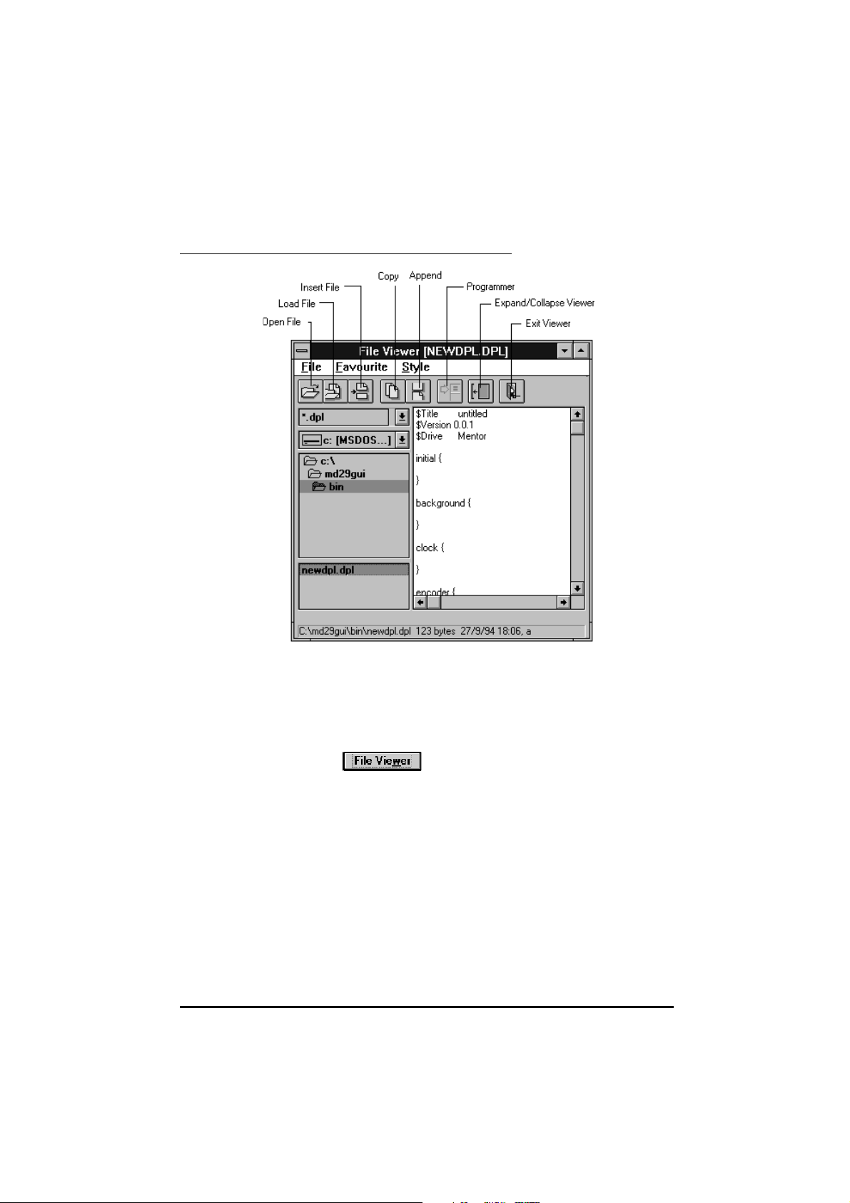
File Viewer
File ViewerFile Viewer allows the user to perform the following:
• View a file without opening it
• Copy text from an unopened file and paste it in the open file
• Pre-select individual lines for copying in one operation
Opening
File Viewer
Do either of the following:
Click on
In the File menu, select View Current File or View Last File.
When View CurrentView Current FileFile is selected, File Viewer appears with the
currently open file loaded.
When View View lastlast filefile is selected, File Viewer appears with the last-saved file
loaded. This file is not necessarily the file that is displayed on the screen.
5-4 DPL toolkit
(File ViewerFile Viewer).
UD70
Issue code: 70nu2
Page 47

Copying and
pasting text
1 Select the file and highlight the text that you want to copy.
2 Click on (CopyCopy).
3 Place the cursor in the required position for the selected text.
4 Open the EditEdit menu and select Paste Paste in the drop-down menu.
Copying and
pasting
sub-routines
Use either of the following procedures to select a sub-routine and paste it
into different programs.
Using File ViewerUsing File Viewer
1 Save the sub-routine as a file. See Chapter 4 DPL Programming.
2 Place the cursor in the open program where the text is to be inserted.
3 Open File Viewer. In the box at the bottom left corner of File Viewer is
a list of saved files.
4 Select the name of the file that contains the required sub-routine.
5 Click on (ViewerViewer InsertInsert).
Using the main toolbarUsing the main toolbar
1 Save the sub-routine as a file. See Chapter 4 DPL Programming.
2 Place the cursor in the open program where the text is to be inserted.
3 Open the Edit menu Edit menu and select Insert File Insert File in the drop-down menu.
UD70
Issue code: 70nu2
DPL toolkit 5-5
Page 48

5.3 Editing a program
Edit menu
The EditEdit menu is as follows:
The basic editing tools are similar to other Windows applications. The tools
allow you to cut, copy, paste, clear and undo.
Cutting a
line
Finding and
replacing
text
Select CutCut Line Line to delete highlighted instruction lines.
Select Find/ReplaceFind/Replace to find and replace characters and words. The Find
dialog box appears.
Use this option in the same way as the Find/Replace option in Windows word
processors.
5-6 DPL toolkit
Issue code: 70nu2
UD70
Page 49

Appending
instruction
lines
BookMarks
Use the following procedure to copy lines in a specific order from
File Viewer to the program being written:
1 Select in turn the lines shown in File Viewer that are to be copied to
the new program.
2 After each selection, click on (AppendAppend).
3 Place the cursor in the required position for the lines to appear in the
new program.
4 Open the EditEdit menu and select Paste Paste in the drop-down menu.
BookMarks are useful for negotiating long programs. A BookMark is
inserted into a program where the writer needs to refer to a location on a
regular basis. A number of BookMarks may be used in a single program.
Setting a
BookMark
Returning to
a BookMark
Clearing
BookMarks
1 Position the cursor in the program where the BookMark is to be
placed.
2 Click on (BookMarkBookMark).
1 Click on (NextNext BookMarkBookMark).
2 The cursor goes to the BookMarkBookMark that has been placed. If the
Next BookMark button is clicked on again, the cursor highlights the
next BookMark. BookMarks are highlighted in the order they were
placed.
Open the EditEdit menu, and select ClearClear AllAll BookMarksBookMarks.
UD70
Issue code: 70nu2
DPL toolkit 5-7
Page 50

5.4 Applying styles
The StyleStyle menu is as follows:
Styles
Styles let you alter the way the DPL Toolkit screen appears. There are 48
background and text colours giving over 2000 combinations of colours that
can be used.
Under FontFont, there is an extensive list of text fonts including TrueType fonts.
Auto-indent
AutoIndentAutoIndent allows you to set a tab for DO WHILE...LOOP and IF...ENDIF
commands. When the EnterEnter key is pressed at the end of the line the indent
is automatically retained for the next line. To delete the indent, press the
BackspaceBackspace key.
Using this method of indents, you can easily pick out discrepancies in the
programming by ensuring that an
statement and that a DO statement ends with a LOOP statement (see
Chapter 7 Reference).
IF statement ends with an ENDIF
5-8 DPL toolkit
Issue code: 70nu2
UD70
Page 51

5.5 Compiling and running a program
Task Manager toolbar
The DPL Task Manager contains powerful compilation and debugging tools.
These tools enable the programmer to check the program in great detail.
Some of the debugging tools are automatic and check for programming
errors. Others allow the programmer to check the program line by line to
verify the logic of the program.
Compiling a program
1 Save the written program as a .DPL file.
2 Click on (CompileCompile), or to compile and download the program
automatically, click on:
The Compile...Compile... dialog box appears.
Normally the options can be left as they are shown. In this case, to continue
the compilation process click on:
UD70
Issue code: 70nu2
DPL toolkit 5-9
Page 52

Debugging options
The debugging options enable various debugging aids for the DPL program
to be de-selected. See Program monitoring and debugging below for a
description of these options.
If errors are encountered in compiling the file, the Build ErrorsBuild Errors window
appears showing the program errors. As each error is highlighted in
BuildBuild Errors Errors, the corresponding line in the program is also highlighted.
Using Build
Errors
1 Click on the first line that is shown as an error.
2 Correct the error (the type of error is indicated in the Build ErrorsBuild Errors
window).
3 Click on .
4 Click on in the Save ChangesSave Changes dialog box that appears.
5 Repeat the compile process to update the compiled program.
Note
The debugging tools in the compiler highlights problems in
the program that are attributed to programming errors.
The debugging tools will not highlight problems due to
logic. If a program has been compiled and downloaded to
the UD70 but it appears not to be running, it is likely to be a
logic problem.
5-10 DPL toolkit
Issue code: 70nu2
UD70
Page 53

Errors and warnings
An error indicates that the compiler could not interpret a line or command in
the DPL program. This could occur if a command is mis-spelt, incorrectly
used, etc.
A warning indicates that the compiler understood the commands but the
code may not function in the way you expected. The most common
warning is Possible loss of accuracy in assignment, and can occur when
integer variables or parameters are assigned a floating-point value.
A full list of errors and warnings can be found in Chapter 9 Diagnostics.
5.6 Downloading a program
A program can be downloaded only when it is free from errors.errors. Once the
program file is downloaded to the UD70, the DPL program is ready to be run.
To download the file, click on
Task Manager toolbar.
If Auto-Run
after downloading and the UD70 is initialized (reading the
set-up parameters).
Warning
is selected, the program will automatically run
Compiling and downloading a program
To compile and download a program in a single step, click on
Alternatively, select Quick StartQuick Start from the ProjectProject menu.
If any errors are encountered, the download process will not occur. If the
program contains warnings only, the Build + ProgramBuild + Program dialog box appears.
To ignore the warnings and continue to download, click on the ContinueContinue
button, otherwise click on the StopStop button.
(Down-loadDown-load) in the
UD70
Issue code: 70nu2
DPL toolkit 5-11
Page 54

5.7 Running a program
Click on (RestartRestart). This runs the DPL program from the beginning
(ie. at the INITIAL task). The Task Manager buttons for the tasks present in
the program are made active.
Stopping the program
Click on (PausePause).
Resuming the program
Click again on (PausePause).
5.8 Program monitoring and debugging facilities
Single-stepping
Single-stepping executes only one line of a DPL program at a time. By using
single-stepping, the operation of a program can be monitored instructionby-instruction. During single-stepping, all other tasks may run at full speed.
Singlestepping
through a
task
1 Click on the appropriate Task Manager button, as follows:
INITIAL task
BACKGROUND task
CLOCK task
ENCODER task
SPEED task
single-stepped.)
advance the execution point to the next line.
• Hold down the CtrlCtrl key and click on the appropriate Task Manager
button.
• Open the Run Run menu and select the appropriate Run TaskRun Task option.
Clear singlestepping
This halts the selected task. (The
2 Repeatedly clicking on the appropriate Task Manager button will
Use either of the following methods to clear the single-stepping function:
5-12 DPL toolkit
EVENT task cannot be
UD70
Issue code: 70nu2
Page 55

Breakpoints
Setting a
breakpoint
Note
A breakpoint is a line in a task at which point the task will stop the program
running and enter into single-stepping mode.
Breakpoints are useful for checking when a program reaches a particular
piece of code, or for checking the state of DPL variables at a particular point.
1 Place the cursor on the line where the breakpoint is to be set.
2 Click on (Set breakpointSet breakpoint). The breakpoint is now active.
When the program execution reaches the set line, the task is halted
and single-stepping mode is started.
Only one breakpoint may be set in a task at any one time.
Breakpoints and single-stepping are not possible in user
sub-routines.
Finding
breakpoints
in separate
tasks
Removing
breakpoints
1 Click on (Next breakpointNext breakpoint). The cursor goes to the next
breakpoint in the DPL program.
1 Place the cursor on the line where the Breakpoint is to be removed, or
use the Next breakpointNext breakpoint button to find the line that has the
breakpoint.
2 Click on the Set breakpointSet breakpoint button.
Using the Watch window
The Watch Watch window enables the programmer to check the logic of the
program while it is running in the UD70 by reading and writing parameters
and variables.
To display the Watch Watch window, click on
in the Task Manager toolbar.
UD70
Issue code: 70nu2
DPL toolkit 5-13
Page 56

Continuously
monitoring a
variable or a
parameter
Example displayExample display inin the the WatchWatch windowwindow
There are two section to the WatchWatch window. The top section shows the
values of the parameters and variables being continuouslycontinuously updated while
the program is running. Values can be shown numerically and graphically.
The bottom section allows snap-shot reading and writing of parameters and
program variables.
There are five ways of viewing an item in the top section of the
WatchWatch window, as follows:
Display method Button
Value only
Value with uni-polar bar graph
Value with bi-polar bar graph
Value with bi-polar line graph
Value with individual bits displayed
5-14 DPL toolkit
Issue code: 70nu2
UD70
Page 57

Use the following procedure for monitoring a parameter or variable:
1 Click on the toolbar button for the required display method.
2 Select the required parameter or variable to be watched, using one of
the following methods:
• In the parameter text box on the left, type in the name of the
parameter or variable to be watched.
Using the
lower
section of
the Watch
window
• Click on
and select the required parameter or variable from
the list that appears.
• Double-click on the parameter or variable name in the main DPL
Toolkit editor window.
Changing the full-scale value
The full-scale value for the graphical display defaults to 1000. To alter this,
double click in the value display box. In the Max Value Max Value dialog box that
appears, type the required value for full-scale. Click on the OKOK button.
Changing to and from bipolar values
To change the graphical display for a watched item from one type to
another (eg. uni-polar bar to bi-polar), move the mouse cursor over the
graphical display region and press the right mouse-button. In the pop-up
menu appears, select the required option.
The lower section of the WatchWatch window allows the user to take an
instantaneous reading of a variable or parameter, and also write to any
variable or parameter.
Reading a parameter or variable
1 Type the parameter or variable name (eg. #1.21#1.21).
2 Press ENTER. The value is shown at the right of the parameter/variable
name.
Setting a value for a parameter or variable
1 Type the parameter or variable name, followed by an equals sign and
the value to be written (eg. #1.21 = 1000#1.21 = 1000)
2 Press ENTER. If the value was written successfully, OKOK is displayed at
the right.
A parameter or variable entered in the lower section, can be
automatically added to the top section by pressing the
ENTER keys after typing the name.
SHIFT and
Note
UD70
Issue code: 70nu2
If any changes are made to the program, it has to be
re-saved, compiled and downloaded to the UD70.
DPL toolkit 5-15
Page 58

Saving the
Watch
window
settings
The settings of the WatchWatch window can be saved onto disk for later use. To
achieve this, select SaveSave in the FileFile menu of the WatchWatch window.
Further details of the WatchWatch window are covered in the on-line help facility.
Press F1 at any time to display the on-line help.
Uploading the DPL source file
from the UD70 to the host PC
The .DPL source file can be uploaded to the host PC when the original
program file is not available or if the program that is running is not
exactly known.
Use the following procedure to retrieve the .
1 Click on (UploadUpload ) in the DPL Task Manager toolbar. If a
version of the
appears asking if the file is to overwritten.
2 To find out which program is resident in the UD70, and to attempt to
load it, click on:
DPL file:
DPL program already exists in the host PC, a dialog box
Important Note
(Source codeSource code)
It is safer to upload the *.DPL program from the UD70 than
to retrieve the source code from the host PC, unless you
are sure that the program that is in the host is the
required program.
5-16 DPL toolkit
Issue code: 70nu2
UD70
Page 59

System information
System information gives the user information about the program in the
UD70, such as the program name, date of compiling, version number of the
UD70 operating system, etc.
To view this information, click on
System InformationSystem Information message box appears, eg:
(System informationSystem information). The
UD70
Issue code: 70nu2
DPL toolkit 5-17
Page 60
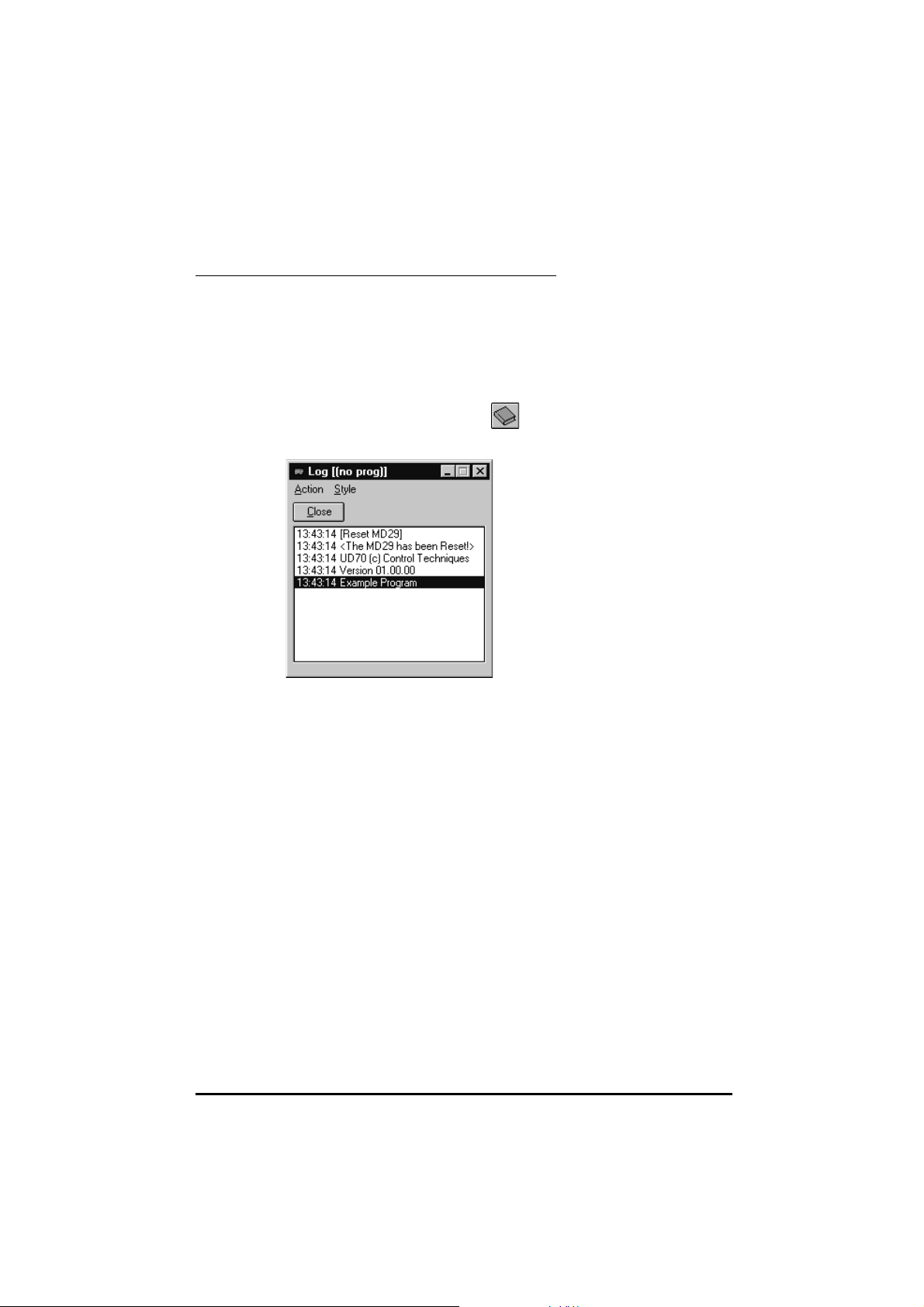
The Log window
The Log window can be used to show the following:
These functions are enabled and disabled using the Action menu.
• System messages (eg. the starting and stopping of a program)
• Watch window values (useful for data logging)
• The output of the DPL
Chapter 7, Reference).
PRINT instruction (see PRINT instruction in
To open the Log window, click on
window appears:
(Log window). The Log
5-18 DPL toolkit
Issue code: 70nu2
UD70
Page 61
6 Serial Communications
6.1 Introduction
A serial communications link enables one or more UD70 cards to be used in
systems controlled by a host unit such as a PLC or computer. The
communications link uses the RS485 standard.
The
UD70 may also act as the host in a system, controlling Drives, UD70
modules, MD29 cards or other devices fitted with a suitable interface.
The host controller can operate up to thirty-two
use of line repeaters. Each transmitter and receiver of Control Techniques
devices loads the line by two unit-loads. Therefore in two-wire mode, each
Control Techniques device loads the line by four unit-loads. This means that
no more than a total of seven such devices can be connected in a single
group, allowing up to four unit-loads for the line repeater. Up to 15 devices
can be connected if four-wire mode is used.
When line repeaters are used, up to 81 Control Techniques devices can be
operated. In this case the devices are organized in up to nine groups of nine.
A particular group or groups can be given commands without affecting
other devices or groups of devices.
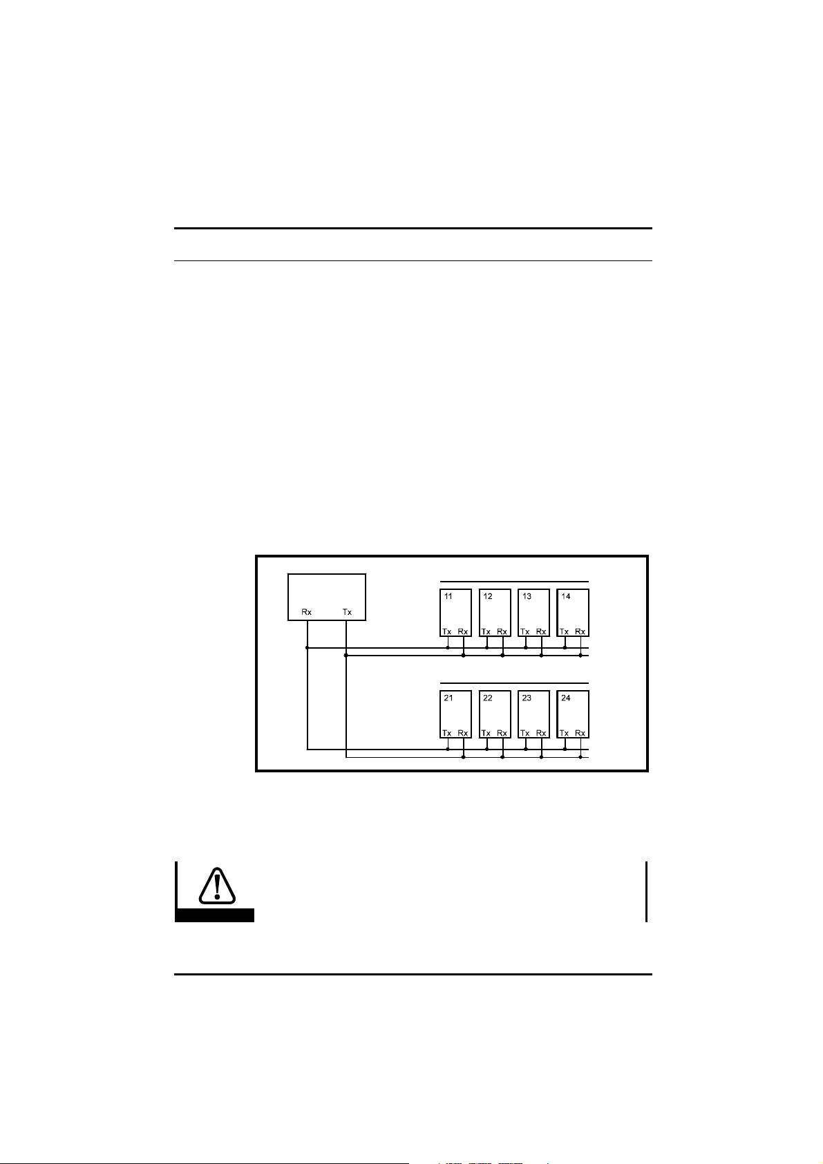
EIA RS485 devices with the
RS485 mulitdrop link having two groups of four unitsRS485 mulitdrop link having two groups of four units
The communications port of the
right side of the board. The UD70 may be used in either 4-wire or 2-wire
mode. The RS485 port is fully opto-isolated. RS422 is also supported.
Caution
UD70
Issue code: 70nu2
Host controller
An RS232 connection may be made to the RS485 port, but is not
recommended due to its inferior specification (noise
rejection, limited maximum cable length, etc). RS232 is not
the same as two-wire RS485.
Group 1
Group 2
UD70 is the male D-type connector on the
Serial communications 6-1
Page 62

6.2 Hardware connections
The following table details the hardware connections for the RS485
communications port.
Pin RS485 4-wire RS485 2-wire
1
2
3
4 DI0 *DI0 * DI0 *DI0 *
5 DI1 *DI1 * DI1 *DI1 *
6TxTx Tx/RxTx/Rx
7RxRx Tx/RxTx/Rx
8 DO *DO * DO *DO *
9 0VD *0VD * 0VD *0VD *
* Terminals 4, 5, 8 and 9 form the digital I/O connections of the UD70.
Since they form no part of the serial communications connections they must
not be connected to any serial communications lines, or to the serial
communications 0V (pin 1).
Ground connection
It is recommended that the shield of the data communications cable should
be connected by a low-inductance path to a ‘clean’ ground.
0V
Tx
Rx
0V0V
Tx Rx
Tx Rx
Routing the serial communications cable
A data communications cable should not run parallel to any power cables,
especially ones that connect Drives to motors. If parallel runs are
unavoidable, ensure a minimum spacing of 300mm (1 foot) between the
communications cable and the power cable.
Cables crossing one another at right-angles are unlikely to give trouble.
The maximum cable length for a
RS485 link is 1200 metres (4,000 feet).
6-2 Serial communications
Issue code: 70nu2
UD70
Page 63

Terminating the cable
When a multi-drop RS485 system is used, connect a 120Ω resistor between
the two receive lines of the last unit in the chain (ie. the unit farthest away
from the host). Care must be taken to ensure that other units in the system
do not have the resistor already fitted. Excessive signal loss will occur if
termination resistors are connected to units other than the last one.
Connections for 4-wire modeConnections for 4-wire mode
Connections for 2-wire modeConnections for 2-wire mode
UD70
Issue code: 70nu2
Serial communications 6-3
Page 64

6.3 ANSI communications
Using the standard ANSI slave protocol
The standard built-in protocol which defines the message structure used to
read and write parameters on the UD70 is ANSI x3.28-2.5-A4. This section
explains this protocol.
The user may also create his own protocol by writing it in a DPL program,
using low-level port commands such as
Chapter 7 Reference).
ANSI slave protocol is enabled when the RS485-mode set-up parameter is set
at 1 (4-wire) (which is the default setting), or 5 (2-wire). See Serial
communications modes later in this chapter for details of other
communication modes.
Fundamentals of data transmission
Data is transmitted at a fixed speed or baud rate in the form of a character.
A character may typically comprise seven or eight bits.
In order for a receiver to recognize valid data, a frame is placed around each
character. This frame contains a start bit, a stop bit, and an optional parity
bit. Without this frame, the receiver will be unable to synchronize itself
with the transmitted data.
A frame is shown below:
Low ASCII character byte
1st hex character 2nd hex character
Start bit Seven data bits Parity bit Stop bit
0LSB MSB 1
GETCHAR and PUTCHAR (refer to
This is known as a 10-bit frame, since there are 10 bits transmitted in total.
The format is often described as follows:
1 start bit, 7 data bits, even/odd/no parity, 1 stop bit.1 start bit, 7 data bits, even/odd/no parity, 1 stop bit.
lsb refers to the least significant bit (ie. bit 0)
msb refers to the most significant bit (bit 6)
The Parity bit is used by the receiver to check the integrity of the data
it has received
6-4 Serial communications
Issue code: 70nu2
UD70
Page 65

The character set used is called the low ASCII set. The set comprises 128
characters decimally numbered from 0 to 127. The first 32 characters in the
ASCII set (hex. 00 to 1F) are used to represent special codes. These are the
control codes, each of which has a particular meaning (eg. start of text is
called STX and is ASCII code 02.)
On a computer or terminal, the
pressing CtrlCtrl+BB. When the UD70 is in standard ANSI mode, it recognizes
that a command follows the ST X character.
The control code
Drives on the RS485 bus to be ready to receive a new message — it is often
sent at the start of a message so that all the devices are set at Ready to Ready to
receive messagereceive message.
Control characters
Commands and requests are sent in message packets. Each message is
started with a special control character, and may contain control characters.
A list of all the control characters that can be used when sending a message,
and receiving is as follows:
STX character may be transmitted by
EOT (end of transmission) instructs all UD70 cards and
Character Meaning ASCII code
(decimal)
EOT Reset
Instructs the UD70 to prepare for a new message.
Also indicates parameter does not exist.
ENQ Enquiry
Used when interrogating.
STX Start of text
Used to start a command.
ETX End of text
Used at the end of a command.
ACK Acknowledge (message accepted) 06 Ctrl F
NAK Negative acknowledge (message not understood) 21 Ctrl U
BS Backspace (go to previous parameter) 08 Ctrl H
04 Ctrl D
05 Ctrl E
02 Ctrl B
03 Ctrl C
Keyed as...
UD70
Issue code: 70nu2
Serial communications 6-5
Page 66

Baud rate
Addressing
Note
The user can select a baud rate between 300 and 38400. The default is
4800. See setup parameters.
Each unit on an ANSI communications bus must be given a unique identity or
address so that only the target UD70 unit will respond. The address
comprises two parts:
• The Group Address which is the first digit.
• The Unit Address which is the second digit.
Both the group address and unit address have a range of 1 to 9. A group or
unit address of 0 is not allowed (addresses 01, 10, 20, etc. are invalid). The
reason for this is that
(up to 9 units per group), and a message can be sent over the ANSI
communications bus to all units of the group. To address a particular
group, the unit address of zero (0) is used. For example, to address all units
of group 6 the full address will be 60.
An additional feature is that a message can be sent to all units of all groups
simultaneously using the address 00. This address can be used to send a
Start command to a group of Drives which are mechanically coupled
together to drive a conveyer line. All the Drives will then start
simultaneously.
It is important to realize that when using group
addressing, the UD70 cards will not acknowledge the
command. (If several cards try to reply at the same time,
they would cause meaningless data to appear on the serial
communications bus.)
UD70 cards and some Drives can be grouped together
For data integrity, the format of the transmitted address requires that each
digit of the two-digit address is repeated: the address of UD70 number 23 is
sent as four characters, eg:
2 2 3 3
The serial address follows immediately after the first control character of
the message (
EOT).
Parameter identification
All parameters are identified by four digits representing the menu and the
parameter number, but without the decimal point.
Example
To send a message to menu 4, parameter 8, write 0408 (the leading
zero must be included)
To send a message to menu 18, parameter 11, write 18111811.
6-6 Serial communications
Issue code: 70nu2
UD70
Page 67

Data field
Control
ENQ
Data to be sent or requested occupies the characters immediately after the
parameter number. The minimum length of the data field within a message
structure is two characters.
The data is normally expressed as a decimal numeric value. Hexadecimal
format may also be used by specifying the first character of the data field as
a
X.
The first character of the data field (
D1) can be only one of the following:
Space (32 dec.)
+
–
X (for hex.) — hex. is typically used to access I/O Box data.
Block checksum (BCC)
In order to ensure that the messages from or to the UD70 do not become
corrupted during transmission, all write messages and data responses are
terminated by the block checksum character (BCC). See Calculating the
block checksum (BCC) later in this section.
Reading parameters
To read a parameter, the following message is sent:
Control Address Parameter
EOT GAGAUAUAM1M2 P1 P2
Where:
GA = Group Address
UA = Unit Address
M1 M2 = Menu number
P1 P2 = Parameter number
Note
UD70
Issue code: 70nu2
No BCC character is sent in this message.
Serial communications 6-7
Page 68

The UD70 will reply with the following structure if the message is
Control
ENQ
understood:
Control Parameter Data Control BCC
STX M1 M2 P1 P2 D1 ... Dn ETX BCC
Where:
M1 M2 = Menu number
P1 P2 = Parameter number
D1...Dn = Data
First character:
+ or Space for positive values
– for negative values
XX for hex. values
BCC = Block checksum
If a requested parameter does not exist, the
UD70 will reply with an EOT
character (ASCII 04).
Example
Control Address Parameter
STX 1 122012 1
To read the speed set-point of a Unidrive that is unit 2 of group 1, send:
The unit replies as follows:
Control Parameter Data Control BCC
STX 0 1 2 1 – 4 7 . 6 ETX 7
Note
When the UD70 replies to a command, the length of the
data field returned is variable, depending upon the type of
Drive, and the parameter being read.
6-8 Serial communications
Issue code: 70nu2
UD70
Page 69

Re-reading data
Control
Once a read message has been received and understood (ie. valid data was
returned), to request the parameter again, request the next parameter, or
the previous parameter, a single control code character may be sent. These
control codes are:
Control
Code
NAK Return the value of the same parameter Ctrl U
ACK Read the next parameter Ctrl F
BS Read the previous parameter Ctrl H
Function Keyed as...
This facility can be used to save time when monitoring a parameter over a
period of time.
Writing to parameters
To write data to a parameter (Drive or virtual), the message structure is
comprised as follows:
Control Address Control Parameter Data
EOT GA GA UA UA STX M1 M2 P1 P2 D1 ... Dn ETX
Where:
GA = Group address
GU = Unit address
M1 M2 = Menu number
P1 P2 = Parameter number
D1...DN = Data
First character:
+ or Space for positive values
–– for negative values
XX for hex. values
BCC = Block checksum
The data field can be of a variable length with the maximum length being
dependent on the parameter being edited.
BCC
UD70
Issue code: 70nu2
Serial communications 6-9
Page 70

The UD70 will respond with a single control character, as follows:
Control Code Meaning
ACK Acknowledge — Message has been understood and implemented.
NAK Message invalid, data is too long or out of range, parameter is invalid, parameter is
read-only, or the BCC is incorrect.
Example
Control Address Control Parameter Data Control BCC
EOT 2 2 6 6 STX 0 1 2 1 + 0 7 6 . 4 ETX 1
Set parameter Pre-set frequency 1Pre-set frequency 1 at +76.4 for Unidrive (unit 6, group 2) send:
Re-writing data
Once a write message which includes the address field has been sent and
accepted with either a <ACK> or <NAK> response, subsequent write
messages to that particular UD70 can use a re-write message structure in
which the address does not need to be re-transmitted. The re-write
structure is as follows:
STX M1 M2 P1 P2 D1 ... Dn ETX BCC
When a different UD70 is addressed, or an invalid character is received, the
re-write facility no longer functions. The first UD70 can be addressed again
only by using the full write message with the address.
Calculating the block checksum (BCC)
The block checksum is calculated by applying an exclusive OR function to all
of the characters of a message after the ST X control character.
XOR truth table
ABOut
000
01 1
101
110
For example, the serial command to set Pre-set speed 1Pre-set speed 1 at
–34.5Hz on a Unidrive:
6-10 Serial communications
Issue code: 70nu2
UD70
Page 71

The message will be:
Control Address Control Parameter Data Control BCC
EOT 1 1 2 2 STX 0 1 2 1 – 3 4 . 5 ETX 0
Not included in the calculation Included in the calculation Result
The first character of the BCC calculation is 0 0 (00110000 in binary), the value
of which is taken as a starting or result value. The next character is 1 1
(00110001 in binary), which now has the exclusive OR (XOR) operator act
upon it. With the previous result value, a new result occurs of 00000001 in
binary.
The complete calculation is show in the table below:
Character Binary Value XOR result
0 0011 0000 –
1 0011 0001 0000 0001
2 0011 0010 0011 0011
1 0011 0001 0000 0010
– 0010 1101 0010 1111
3 0011 0011 0001 1100
4 0011 0100 0010 1000
. 0010 1110 0000 0110
5 0011 0101 0011 0011
ETX 0000 0011 0011 0000
The final value is the BCC, provided that its equivalent decimal value exceeds
31 (ASCII characters from 00 to 31 are used as control codes).
When the final
XOR result produces a decimal value less than 32, 32 is added.
In this example, 0011 0000 is 48 decimal which is above 31, so this is the final
BCC value. 48 decimal is the character 0. The complete message will be:
Example
QuickBasic program to calculate BCC
In
the BCC.
UD70
Issue code: 70nu2
EOT 1 1 2 2 STX 0 1 2 1 - 3 4 . 5 ETX 0
mess$ = CHR$(4)+”1122”+CHR$(2)+”0125”+”-34.5”+CHR$(3)
bcc% = 0
FOR n% = 7 to LEN(mess$)‘start at the character after ‘chr$(2).
bcc% = bcc% XOR ASC(MID$(mess$, n%, 1))
NEXT
IF bcc% < 32 THEN bcc% = bcc% + 32
mess$ = mess$ + CHR$(bcc%)
PRINT mess$
DPL, the ANSIREAD and ANSIWRITE functions automatically calculate
Serial communications 6-11
Page 72

6.4 Serial communications modes
The UD70 has eleven communication modes as follows:
• 4-wire and 2-wire standard
• High-speed parameter transfer
• Programmable master/slave modes
• User modes
• I/O Box mode
The available options are as follows (see Set-up parameters in Chapter 10
Parameters for details of the actual parameters):
ANSI slave
Mode 1
Mode 2
Mode 3
Mode 4
Standard 4-wire
RS485 using ANSI slave protocol (default).
Master mode
In this mode, data is taken from the defined parameter, scaled to ±16000
then continuously transmitted out to a slave Drive. The slave unit can be
an MD29, a Unidrive standard communications option module, a Mentor II
Drive, a CDE Drive or another UD70.
Slave mode
In this mode, data is received from the serial port and is scaled by the value
of the scaling set-up parameter before being placed in the destination
parameter.
Cascade mode
With this mode, a defined parameter is transmitted to a remote Drive unit
(no scaling) and received data is placed into the destination parameter.
The data is not scaled.
The transmitting unit and/or receiving unit can be either another
MD29, Unidrive with standard communications option module, or a Mentor II
Drive.
This mode is typically used in wire-drawing type applications – the first
Drive is given a speed reference from an external source (eg. a
potentiometer). Mode 4 communications are used to pass that reference
down to the next Drive on the line which uses an Applications Option to
receive the data and apply draw. That Drive then passes the new reference
down to the next Drive, etc.
UD70,
Mode 5
2-wire RS485
Using standard ANSI slave protocol. Note that RS232 is not 2-wire RS485.
6-12 Serial communications
Issue code: 70nu2
UD70
Page 73

Mode 6
User mode
This mode turns off all internal protocols and allows the user to use the
RS485 port directly from a DPL program. Typically, this mode will be used
in conjunction with the DPL ANSI master commands (ANSIREAD , AN SIWRITE,
etc.). User-defined protocols can also be implemented in DPL with the lowlevel PUTCHAR and GETCHAR commands. The communications data-frame
is organized as follows:
1 start bit, 7 data bits,
EVEN parity, 1 stop bit, 10 bits total
Mode 7
Mode 8
Mode 9
Mode 10
Mode 11
User mode
This mode turns off all internal protocols and allows the user to write and
read directly from the
ANSI port using the PUTCHAR and GETCHAR functions.
The communications data-frame is organized as follows:
1 start bit, 8 data bits,
EVEN parity, 1 stop bit, 11 bits total
User mode
This mode turns off all internal protocols and allows the user to write and
read directly from the
ANSI RS485 port using the PUTCHAR and GETCHAR
functions. The communications data-frame is organized as:
1 start bit, 8 data bits,
NO parity, 1 stop bit, 10 bits total
User mode
The communications data-frame is organized as:
1 start bit, 9 data bits, NO parity, 1 stop bit, 11 bits total
I/O Box mode
This mode allows a single I/O Box to be connected directly to the UD70
using the EIA RS485 port.
If multiple I/O Boxes are required, they must be set up in standard ANSI
mode. Mode 6 must be selected, and the DPL RS485 commands must be
used to transfer data.
User mode
This mode bypasses the internal software buffers and interfaces directly to
the hardware. This reduces the delay in passing data through the UD70
RS485 port. The baud rate is programmable, as with the other modes.
The communications data-frame is organized as:
1 start bit, 9 data bits, NO parity, 1 stop bit, 11 bits total
UD70
Issue code: 70nu2
Serial communications 6-13
Page 74

Mode 12
Mode 13
Mode 14
Reserved
Modbus – RTU (slave mode only)
Modbus – ASCII (slave mode only)
The Modbus RTU and ASCII slave modes support the functions Read
Multiple Registers, Preset Single Registers and Preset Multiple Registers.
This mode limits the number of consecutive registers to 20, and the node
address range is limited from 11 to 99.
Contact your local Drive Centre for information about the Modbus
Protocol.
Note
Using Modes 2 and 3
There is minimal data integrity checking with modes 2, 3
and 4.
Source
Any parameter Serial link
UD70 operating in Mode 2 UD70 operating in Mode 3
Functions of Modes 2 and 3Functions of Modes 2 and 3
Using Modes 6, 7, 8 and 9
In Modes 6, 7 or 8, it is possible to use the UD70 as an ANSI master device
controlling other UD70 modules, MD29 cards, Drives or other ANSI compliant
devices. This facility may alleviate the need for a custom computer or PLC
to control a system or process. When an I/O Box is used, there may be no
need for a PLC in a system.
Modes 6 to 9 also allow you to create custom serial protocols which you
may use for communicating with nonintelligent display modules, etc.
The
ANSI RS485 port is buffered as follows:
Receive: 60 bytes
Transmit: 25 bytes
Scale
±16000
Destination
Scale
#xx.xx
Any parameter
ANSI compliant devices such as
6-14 Serial communications
Issue code: 70nu2
UD70
Page 75

Using Mode 11
When other modes are used, the start of data transmission and reception
can be delayed up to 8ms. When mode 11 is used, the data bypasses the
internal software FIFO, buffer which reduces the delays in the system.
Parameter #17.07 is used to program the baud rate.
Using modes 13 and 14
The Modbus protocol is only supported as a slave. Modes 13 and 14 do not
allow the UD70 to act as a Modbus Master. The baud rate is selected using
parameter #17.07.
6.5 ANSI instructions
The following RS485 ANSI instructions are available:
ANSIREAD Issue a Read command to a remote unit
ANSIREPLY Read a reply from a remote unit
ANSIWRITE Issue a Write command to a remote unit
GETCHAR Receive a single character directly
PUTCHAR Transmit a single character directly
Refer to Chapter 7 Reference for information about these commands.
UD70
Issue code: 70nu2
Serial communications 6-15
Page 76

6.6 Example ANSI instructions
The following program fragment gives an example of reading a speed
reference from a Unidrive, and writing it to a CD Drive.
Both Drives are connected to the RS485 bus. The Unidrive is at address 11;
the CD Drive is at address 12.
For this program to operate, the RS485 mode should be set at 6.
BA CKGROUND{
top:
// send read command to read parameter #1.21
result% = ANSIREA D(11, “0121”)
IF result% = 0 THEN
PRINT “Message could not be sent”
GOTO top:
ENDIF
CALL get
IF reply% <= –65536 THEN // val id reply?
ENDIF
// send write command to CD, using 1 decimal place
result% = ANSIWRITE(12,”SP”, reply%, 1)
IF result% = 0 THEN
ENDIF
CALL get
IF reply% <> -65540 THEN // –65540 is ACK
ENDIF
GOTO top:
}
get_re p l y: { // sub -ro utine to wai t fo r a re p l y
}
CLOCK {
timeo ut% = time out% + 1 // inc re m e nt timeout varia b l e
}
Note
Refer to the help file in the DPL Toolkit for further
examples of the ANSI commands.
_reply: // get reply from read command
PRINT “Error in reading data from Unidrive”
GOTO top:
PRINT “Message could not be sent”
GOTO top:
_reply: // write accepted?
PRINT “Error in sen di n g message to CD”
timeout% = 0 // reset timer
DO
// retu rns –65536 i f the reply has not been received yet
reply% = ANSIREPLY
LOOP WHILE reply% = –65536 AND timeout% < 50
// loop exits only wh en a reply has been received, or
// a time-ou t h as occu rred.
// if th e clock task is set at 5ms, the timeout will be 250ms
6-16 Serial communications
Issue code: 70nu2
UD70
Page 77

7 Reference
7.1 Tasks
Refer also to Tasks and real-time programming in Chapter 4
DPL Programming.
INITIAL task
The INITIAL task is used typically to initialize program variables and Drive
parameters.
The
INITIAL task boots-up the DPL program and runs only when the UD70 is
reset or at the moment AC power is applied to the Drive.
The
INITIAL task is special in that all other tasks are guaranteed not to be
running when it is being run. This is significant when other real-time Tasks
are to manipulate data which have initial values.
BACKGROUND task
The BACKGROU N D task is used for functions and commands that do not
require time-related or encoder-related monitoring. It would be used for
the following:
• Data logging
• Checking digital inputs
• Setting output status
BACKGROU ND task runs after the INITIAL task is completed. It is
The
recommended that the majority of the program is run in the BACKGRO UN D
Task.
Note
Example
UD70
Issue code: 70nu2
The BACKGROUND task does not automatically loop.
BACKGROUND{
RAMP:
#1. 21 = 0
DO WHILE #1.21 < 1000
#1.21 = #1.21+1
LOOP
GOTO RAMP:
}
Reference 7-1
Page 78

CLOCK task
Example
SPEED task
The CLOCK task is used for time-critical monitoring of the Drive and
commands to the Drive (eg. controlled acceleration or deceleration ramp).
The
CLOCK task is executed on a fixed timebase, asynchronously to the
Drive. The actual timebase used depends on the set-up parameter (see Setup Parameters in Chapter 10 Parameters), which can range from 5ms to
200ms).
This example produces a sine wave.
CLOCK{
#1.21 = SIN (rad)*1000
r ad = rad+0.01
IF rad>6.283185 THEN
rad = 0
ENDIF
}
The SPEED task is synchronized with the speed-control loop in the Unidrive.
This causes the execution frequency of the task to be determined by the
PWM switching frequency.
Drive Switching
Unidrive 3, 6 or 12 1.38
Unidrive 4.5 or 9 1.84
7-2 Reference
frequency
kHz ms
SPEED task
timebase
UD70
Issue code: 70nu2
Page 79

ENCODER task
A typical use for the ENCODER task is to monitor the activity of an encoder.
The
ENCODER task is synchronized with the speed-control loop in the
Unidrive, and is executed at every fourth SPEED task cycle. Actual
execution frequency of the task is determined by the PWM switching
frequency.
Example
EVENT task
ERROR task
PWM switching
frequency
kHz ms
3, 6 or 12 5.52
4.5 or 9 7.36
ENCODER{
master% = #90.2
slave% = #90.4
EPOS = EPOS + master% – slave%
}
The EVENT task is a special task which runs when a specific event occurs.
The source of the event is determined by the Timer/Counter Unit.
Refer to Timer/Counter Unit in Chapter 8 Features for further information.
The ERROR task is executed when a run-time error occurs in a DPL program.
Refer to section Advanced error-handling in Chapter 9 Diagnostics for
further information.
ENCODER task
timebase
UD70
Issue code: 70nu2
Reference 7-3
Page 80

User-defined task
User-defined tasks are sub-routines written by the user and are used in
conjunction with the CALL instruction (see
section).
User-defined tasks can be given any name and can be defined anywhere in
the program.
Example
Note that this task is named RA M P:.
BACKGROUND{
L oop:
CALL RAMP:
GOTO Loop:
}
RAMP: {
#1. 21=0
DO WHILE #1.21<1500
#1.12=#1. 21+1
LOOP
}
CALL
instruction later in this
Case
sensitivity
The name for the sub-routine is case sensitive. If the CALL instruction in the
preceding example is written as CALL ramp ramp, the program will not be
compiled since the word rampramp should be in upper-case letters. Note that
the compiler error that is displayed will be as follows:
Undefined reference to
NOTES task
This is a pseudo task that is ignored by the compiler. The writer of the
program can use the NOTES task for information for the user.
Example
NOTES{
You can put your documentation he re.
}
CONST section
The CONST section is used to define constant arrays data and is not a Task.
See Variables in Chapter 4 DPL Programming.
7-4 Reference
_0103ramp.
UD70
Issue code: 70nu2
Page 81

7.2 Instructions and functions
The following instructions and functions may contain more than one form of
syntax. Where there is more than one form, the first is for use with integer
variables; the second is for use with floating-point variables. (See Chapter 4
DPL Programming).
ABS
Syntax
Example
ANSIREAD
Syntax
Note
Example
result% = ABS (expression%)
result = ABS (expression)
This mathematical function returns the absolute value of an expression
without taking into account either the negative or positive sign of the
expression (negative numbers are made positive).
ABS(45.5 – 100) ;the output is 54.5
result% = ANS I R E A D (d ri ve address%, “m n emon i c”)
This is a 4-wire
This function transmits a parameter read-request via the
a remote Drive or unit.
The Drive address is an integer expression, usually between 01 and 99.
The mnemonic is a string which contains the parameter number. The
format and length of this string depends on the remote Drive.
The function returns 11 if the read request was sent successfully, or 00 if the
message could not be sent (eg. transmission already in progress).
The ANSIREAD instruction does not wait for a response from
the remote Drive.
result% = ANSIREAD(12,”0122”) \\ read #1.22 from drive 12
RS485 port function which always returns an integer.
ANSI RS485 port to
See also Example ANSI commands in Chapter 6 Serial Communications.
UD70
Issue code: 70nu2
Reference 7-5
Page 82

ANSIREPLY
Syntax
ANSIWRITE
Syntax
result% = ANSIREPLY
This is a 4-wire
ANSIREAD and ANSIWRITE functions. This function is typically used to obtain
RS485 port function which is used in conjunction with the
the returned data from a Drive immediately after the issuing of ANSIREAD or
ANSIWRITE.
The following information is returned:
–65536 No reply received yet
–65537 Reply received, but with bad checksum
–65538
–65539
–65540
Any other value is the value of the mnemonic written in
EOT received (i.e. parameter does not exist)
NAK received
ACK received
ANSIREAD.
See also Example ANSI commands in Chapter 6 Serial Communications.
result% = ANSIWRITE(
This is a 4-wire
RS485 port function which is used to transmit a parameter
drive address%, “mnemonic”,value%, attribute%
)
write request to a remote Drive via the ANSI RS485 port.
The Drive address is an integer expression, usually between 01 and 99. The
mnemonic is a string which contains the parameter number. The format
and length of this string depends on the Drive. The value must be an
integer expression.
The following are the attribute arguments that are specified:
0No decimal place
1One decimal place
2Two decimal places
3 Three decimal places
128 Hex write to the
CT I/O box
(six characters prefixed by X)
129 Hex write to
130 Hex write to
CD Drive (four characters prefixed by >>)
CD Drive (two characters prefixed by >>)
This function returns 11 if the write request was sent successfully, or 00 if the
message could not be sent (eg. transmission already in progress).
Note
This instruction does not wait for a response from the
remote Drive.
Example
result% = ANSIWRITE(13,”0211”, 150, 1) \\ se t #2.11 to 15.0
on remote drive 13
See also Example ANSI commands in Chapter 6 Serial Communications.
7-6 Reference
Issue code: 70nu2
UD70
Page 83

ARCTAN
Syntax
Example
AVERAGE
Syntax
result = ARCT A N (expressio n )
This mathematical function returns the arctangent of the expression
in radians.
x = ARCTAN(0.8)
This returns the value 0.674740942 radians.
TAN
See also
This signal-processing function returns the running average of the input for
the desired number of samples. The number of samples must be a constant
integer value. The input expression is also an integer.
This function can be used only in the SPEED, C L O C K or ENCODER tasks.
AVERAGE requires execution on a regular timebase.
If a step change of 0 to 1000 is applied to parameter #1.21, the output of the
averager will be as follows (assuming a 5ms clock timebase).
instruction.
result% = AVERAGE (
input expression%, number of samples%
)
Example
See also
UD70
Issue code: 70nu2
CLOCK{
input% = #1.21
#1.22 = AVERAGE (input%, 4)
}
FILTER
instruction.
Reference 7-7
Page 84

BCD2BIN
Syntax
Example
BIN2BCD
Syntax
BCD2SEG
Syntax
int% = BCD2BIN (integer expression%)
This function converts a binary coded decimal number to a normal binary
integer. It is used to operate on digital inputinput data from from the I/O Box
(eg. thumbwheel switches). (Binary coded decimal is a method of writing a
decimal number in a binary format.)
954 in decimal format is represented as 1001 0101 0100 in BCD.
954
100101010100
r% = BCD2BIN(#82.46)
int% = BIN2BCD (integer expression%)
This function converts a normal binary integer to a binary coded decimal
number. It is used to operate on digital output data to the I/O Box
See
BCD2BIN
coded decimal.
This function converts binary coded decimal to 7-segment
used to operate on digital output data to the I/O Box. The output consists
of drive signals for up to three 7-segment display digits, as follows:
instruction for an explanation for converting decimal to binary
int% = BCD2SEG (integer expression%)
.
LED codes and is
Bit number 7 6 5 4 3 2 1 0
Segment – g f e d c b a
The least significant byte represents the first of the three digits. The
maximum value which can be converted is 999. Leading zeroes are sent.
Example
a% = BIN2BCD(123)
seg
_data% = BCD2SEG(a%)
#83.46 = seg
7-8 Reference
_data% ;output 5200646 (0x 4F5B06 = 321)
UD70
Issue code: 70nu2
Page 85

CALL
Example 1
Example 2
Note
COS
Syntax
Syntax
CALL program-label:
This is a flow control instruction which is used to execute a Standard
Application Program, or a user-defined Task. After the sub-routine has been
completed, the program returns to the line following the instruction [
ENCODER{
CALL diglk
//Digital Lock
...Rest of ENCODER T ask
}
INITIAL{
CALL SETUP:
}
SETUP :{ //This is the name of the sub-rou ti n e
#1.21 = 0
}
It is not possible to single-step through a user-defined
task.
The name of the sub-routine is case-sensitive.
resu l t = C O S (exp ressio n )
_encoder: // Standard application Ta sk
CALL].
This mathematical function returns the cosine of an angle expressed in
radians. This function always returns a floating-point variable.
See
Example
CRC16
Syntax
This function is used to calculate a 16-bit
commonly used in serial communications protocols).
UD70
Issue code: 70nu2
SIN
instruction and
value = COS (3.1416)
CRC% = CRC16 (character%, CRC%)
TAN
instruction.
CRC (cycle redundancy check,
Reference 7-9
Page 86

DELAY
DIM
Syntax
Example
Syntax
Example
DELAY (Integer expression%)
DELAY instruction causes the program to pause for a time specified by
The
the integer expression in increments of 0.1 second. This instruction cannot
be relied on to produce an accurate time delay. In the worst case, the time
delay could be 100ms shorter than that specified (it will never be longer).
DELAY can be used only in INITIAL or BACKGRO UN D Tasks.
#18.12 = 10 //set parameter 18.12 to 10
DELAY(10) //delay program for 1 second.
#18.12 = 0
DIM variable% [number_of_elements%]
DIM variable [number
The
DIM instruction is used to specify an array of a set of variables of the
same type (integers or floating-point). The instruction does not produce
any code, but tells the compiler to reserve space for a dynamic array.
An array must be specified before the array is used. It is recommended that
an array is specified in the
array is to be used in.
INITIAL{
DIM myarray%[100] //de cla res an inte ge r calle d
//[mya rray] whi ch h as 100 elements.
mya rray%[0] = 1 0 //initialise th e first el ement to 10
mya rray%[1] = 2 0 //initialise th e secon d elem ent to 20
myarray%[99] = 50 //initialise the last element
index% = 1
}
CLOCK{
myarray%[index%] = #3.02 //get speed feedback
index% = index + 1 //increment index counter
IF index % = 100 THEN
index% = 0
ENDIF
}
_of_elements%]
INITIAL Task, but it can be specified in the task the
See also Arrays under Variables in Chapter 4 DPL Programming.
7-10 Reference
Issue code: 70nu2
UD70
Page 87

DO WHILE
Syntax 1
Syntax 2
Syntax 3
Example 1
Example 2
Example 3
DO WHILE Conditional expression
Instruction
LOOP
DO
Instruction
LOOP WHILE Conditional expression
DO WHILE Conditional expression LOOP
This is a loop or iterative instruction which causes a block of instructions to
be repeated until a specific expression becomes false.
Syntax 1Syntax 1 allows the conditional expression be evaluated first. If the
outcome is true, the instructions are executed. The program will continue
in the loop until the conditional expression becomes false.
Syntax 2Syntax 2 allows the instructions be executed first, the conditional
expression is evaluated. This ensures that the instructions in the loop are
executed at least once.
Syntax 3Syntax 3 is identical to Syntax 1, except there are no executing instructions
in the loop.
DO WHILE #1.21 < 1000
#1.21 = #1.21 + 1
LOOP
DO
a = a + 0.001
LOOP WHIL E a < 6
DO WHILE #3.02 > 10 LOOP
(If the value of #3.02 is greater than 10, the program will continue to loop.)
EXIT
Syntax
This is a flow-control instruction which provides a quick method of
terminating the current task.
Example
(If the value of #18.22 is 1, exit from the rest of the
UD70
Issue code: 70nu2
EXIT
CLOCK{
IF #18.22 = 1 THEN EXIT
...
CLOCK task.)
Reference 7-11
Page 88

EXP
Example
FILTER
Example
Syntax
Syntax
result = EXP (expression)
expression
This mathematical function returns the exponential function (e
X = EXP(4.5)
This returns the value 90.0171313.
See also LN instruction.
result% = FILTER (input_expression%, time_consta nt %)
result = FILTER (input expression, time
This is a signal processing function which returns the output of a first-order
filter function with input expression as the input.
The time-constant of the filter depends on the value specified, and how
often the
For a clock timebase of 5ms, the effective filter time-constant would be 4 x
5ms = 20ms.
If a step change of 0 to 1000 is applied to parameter #1.21, the output of the
filter will be as shown in the following diagram.
FILTER instruction is executed.
CLOCK{
#1.21 = FILTER (#7.01, 4)
}
_constant%)
).
Typically, the output reaches the final value after five time-constants.
This function must always be used in the
7-12 Reference
CLOCK, ENCODER or speed tasks.
UD70
Issue code: 70nu2
Page 89

FLOAT
Syntax
Example
GETCHAR
Syntax
GETKEY
Syntax
result = FLOAT (integer expression%
This function converts an integer variable into a floating-point variable.
error% = 123
result = error% / 1000
This produces an output of [result = 0] since 123 / 1000 = 0 in integer
arithmetic. To produce the correct answer, one of the operands need to be
converted to floating-point.
error% = 123
result = FLOAT(error%) / 1000
This produces the correct answer: result = 0.123result = 0.123
INT
See also
This is a
communications port.
The returned value is ––11 if no characters have been received in the buffer,
otherwise the value is the
See also
instruction.
result% = GETCHAR
RS485 port function which reads in a character from the RS485
ASCII code for the character read in.
PUTCHAR
result% = GETKEY
instruction.
This is a
PC
communications are disabled (see Disable Toolkit communications in
Chapter 10, Parameters).
This function can only be used if Dumb-terminal Mode is enabled (see Enable
dumb-terminal mode in Chapter 10 Parameters).
The returned value is the ASCII code of the character read in. If there is no
character, the value is ––11.
The data format of the
See also
UD70
Issue code: 70nu2
RS232 port function which reads in a character from the RS232
communications port. This function can be used only when Toolkit
RS232 port is fixed as follows:
19200 baud, 8 data bits, No parity, 1 start bit, 1 stop bit.
PUTKEY
instruction.
Reference 7-13
Page 90

GOTO
IF
Syntax
Example
Syntax 1
Syntax 2
Syntax 3
Syntax 4
GOTO labe l :
This is an unconditional branch instruction which causes program execution
to jump to, and continue from, the line specified by [label]. When declaring
a label and when indicating which label to go to, a trailing [:] must be written
with the label. The trailing [:] identifies the name as a label. This is different
to other programming languages.
If the
BACKGROU N D task is to be continuously executed, a GOTO instruction
must be included.
BACKGROUND{
top: //this is the n ame o f th e lab el
IF #18.32 = 1 THEN
#1. 21 = 100
ELSE
#1. 21 = 0
ENDIF
GOTO top: //go to the l i n e with th e lab el [top :]
}
IF conditional expression THEN
Instruction
ENDIF
IF conditional expression THEN
Instru cti on if co n d i tion i s tru e
ELSE
Instruction if condition is false
ENDIF
IF conditional expression 1 THEN
Instru cti ons if true, goto ENDIF
ELSEIF conditional expression 2 THEN
Instru cti ons if true, goto ENDIF
ELSEIF conditional expression 3 THEN...
Instru cti ons if true, goto ENDIF
ELSE
Instruction
ENDIF
IF
conditional expression
The conditional instructions IF, THEN, EL SE, EL SEIF and ENDIF perform an
operation until the specified condition is met.
THEN
Instruction
7-14 Reference
Issue code: 70nu2
UD70
Page 91

Example 1
Example 2
Example 3
IF #1.21 = 25 THEN
PR INT “25Hz”
ENDIF
IF a >= b AND (c%>– 1 OR z%>1) THEN
a = b
ELSE
z = z+3
ENDIF
IF A% = 1 THEN
#1. 11 = 0
ELSEIF a% = 2 OR a% = 3 THEN
#1. 11 = 1
ELSEIF a% > 4 THEN
#18.21 = 1
ELSE
#18.21 = 0
ENDIF
Note
Example 3 uses the operator
operators can be used to combine conditional expressions:
AND Logical AND
OR
NOT
The following conditional operators may be used in the conditional
expression:
> Greater than
< Less than
>= Greater than or equal to
<= Less than or equal to
<> Not equal to
The IF instruction for Syntax 1 to Syntax 3 must always end
with ENDIF at the end of the set of conditional instructions.
Logical OR
Logical NOT
OR in the conditional expression. The following
UD70
Issue code: 70nu2
Reference 7-15
Page 92

INT
Note
LIMIT
Syntax 1
Example
Syntax 1
result % = INT (float expression)
This function converts a floating-point variable to an integer variable (see
FLOAT
instruction) and rounds-up the result to the next whole number.
a = 14.234
res% = INT(a) / 2 //conve rts ‘a’ into an integer and di v i d es
//by 2
Result = 7
If the integer value of the float expression exceeds 31 bits
(214783647), the UD70 will trip on Error 50: Maths Error.
result% = LIMIT (expression%, limit_value_expression%)
result = LIMIT (expression, limit_value_ex pression)
This mathematical function limits the value returned to the Drive
parameters. This prevents out-of-range values being written to the
parameters. This function applies to both the negative and positive values
of the expression.
Output
Limit
Example
#1.21 = LIMIT (inc%, 1000)
;if inc% > 1000 then limit to 1000
;if inc% < –1000 then limit to –1000
This limits the output to ±1000.
See also
MIN
instruction and
7-16 Reference
MAX
instruction.
Input
Limit
UD70
Issue code: 70nu2
Page 93

LN
MAX
MIN
Syntax
Example
Syntax
Example
Syntax
Example
result = LN (expression)
This mathematical function returns the natural logarithm of an expression.
y = LN(1.5)
This returns the value 0.405465108
See also
This mathematical function returns the greater of two expressions.
The value returned in b% b% is 100 because a%a% is less than 100. If a%a% is 105, the
value returned in b%b% would be the value of a%a% (105).
This mathematical function returns the smaller of two functions
EXP
instruction.
result% = MAX (expressio n _A%, expression_B%)
result = MAX (expressio n
a% = 12
b% = MAX (a%, 100)
result% = MIN (exp ression _ A%, expression_B%)
result = MIN (expression
a% = 12
b% = MIN(a%, 100)
_A, expression_B)
_A, expression_B)
The value returned in b%b% is 12 because a%a% is less than 100. If a%a% is 105, the
value returned in b%b% would be 100.
UD70
Issue code: 70nu2
Reference 7-17
Page 94

PRINT
Syntax
Operation in
various
tasks
PRINT
Expression list separated with a “,”.
The PRINT instruction outputs strings or values to the PC RS232 serial port of
the UD70. All items in the expression listing must be separated by commas.
Strings are enclosed in double quotes (“ ”).
A tab character (
ASCII 09) is automatically printed between each character
separated by a comma. Negative values are prefixed by a –– sign; positive
values have no prefix.
The way this instruction operates depends on the task, as follows:
In BACKGROUN D Task, the PRINT instruction halts program execution until all
characters are transmitted. It is recommended to use the PRINT instruction
in the BACKGROUND task only.
In the
CLOCK and ENCODER Tasks, program execution continues without
waiting. At 19200 baud rate, it takes 0.5ms to transmit one character. The
PRINT instruction would then quickly over-run the CLOCK or ENCODER Task.
If another PRIN T instruction is executed before the previous PRIN T
instruction is finished the remaining characters are not printed.
The string can contain non–printable characters by using an escape
sequence. This begins with a back-slash [\] character followed by the non–
desired character.
The available characters are as follows:
Character Function ASCII Character
\b Backspace 8
\p Line feed 9
\t Tab 10
Table continued...
Character Function ASCII Character
\f Form feed 12
\r Carriage return 13
\v Vertical tab. 11
\\ Single back-slash 92
\NNN (N is an octal number)
Example
PRINT “Hello\r\n Goodbye\r\n”
This prints the following words:
Hello
Goodbye
7-18 Reference
Issue code: 70nu2
UD70
Page 95

Note
PUTCHAR
Do not over-use the PRINT instruction. It is better to use the
Watch window in the Toolkit in order to monitor
variables.
The
PRINT instruction works in both normal-terminal and
dumb-terminal modes. In normal-terminal mode, the
DPL Toolkit must be used to monitor the print output.
The settings of the RS485 port are fixed at 19200 baud, 8
data bits, 1 stop bit, no parity.
Syntax
PUTKEY
Syntax
Example
REINIT
Syntax
Example
result% = PUT C H A R (ch aracter%)
This is a
communications port.
If the character could not be written (eg. if the
function returns 0 0, otherwise it returns 11.
This is a
communications port when operating in dumb-terminal mode only. If the
function fails, it returns 00, otherwise it returns 11.
See also
Set up parameters are read by the
applied to the Drive or the UD70 is reset. If changes are made to the set-up
parameters by a DPL program, the REIN IT instruction can be used to force
the UD70 to re-read them so that changes can take effect.
This instruction will not cause a reset. The program execution continues
from the next instruction as normal.
RS485 port function that writes a character to the RS485
RS485 port buffer is full), the
result% = PUTKEY (character%)
RS232 port function that writes a character to the RS232
r% = PUTKEY(65) // output 'A' to RS232 port
PRINT
instruction.
REINIT
UD70 only at the moment AC power is
#17.11 = 25 //Change CLOCK task time base to 25ms
rein it //rein itial i z es the UD 7 0 to make ch ange take effect
NOTE
UD70
Issue code: 70nu2
REINIT does not read #17.12, POSITION LOOP ENABLE. To
enable or disable the position loop while the Drive is
running, use _Q20%.31 (see Chapter 8).
Reference 7-19
Page 96

SIN
SGN
SQR
TAN
Syntax
Example
Syntax
Example
Syntax
Example
result = SIN (expressio n )
This mathematical function returns the sine of an angle expressed in radians.
See
COS
instruction and
#1.21 = SIN(3.1416)
result% = SGN (expressio n % )
result = SGN (expressio n )
This mathematical function returns a value indicating the negative or
positive sign of the input expression. When the input value is positive or
zero, the function returns the value of 11. When the input value is negative, it
returns the value of ––11.
PRINT SGN (45), SGN (-16), SGN(0)
This prints values: 1, –1, 1
result = SQR (expressio n )
This mathematical function returns the square-root of an expression.
PRINT SQR (25), SQR (16)
This prints values: 5 and 4
TAN
instruction.
Syntax
Example
result = TAN (exp ression )
This mathematical function returns the tangent of an angle expressed in
radians.
COS
See
instruction and
result = TAN (3.1416)
TIME
Syntax
Example
result% = TI ME
The TIME instruction returns the number of elapsed milliseconds since AC
power was applied or the UD70 was last reset.
t% = TIM E
7-20 Reference
SIN
instruction.
Issue code: 70nu2
UD70
Page 97

WDOG
Notes
Syntax
WDOG
The
WDOG instruction is used to update the DPL program watchdog.
The watchdog facility is enabled by setting the appropriate set-up
parameter at 1, and issuing a
instruction must be executed within every 200ms. If a WDOG instruction is
not executed within 200ms, the Drive trips on Prc2 tripPrc2 trip.
WDOG instruction can be used only in the INITIAL and BACKG R OUND
The
Tasks. The UD70 operating system automatically updates the individual
watchdogs of the real-time tasks.
See the on-line Help for an example.
If any of these tasks are single-stepped a watchdog trip
will occur.
When a watchdog trip occurs, the Drive trips on Prc2.
Because the watchdog trip is a function of the Drive, the
DPL program continues to run.
This function is not available on the Vector Drive.
WDOG instruction. When enabled, the WDOG
UD70
Issue code: 70nu2
Reference 7-21
Page 98

7-22 Reference
Issue code: 70nu2
UD70
Page 99

8 Features
Virtual menu used
for access
#70.xx
#71.xx
#72.xx
#73.xx
This chapter covers the following features of the UD70:
• Single-axis position controller
• Timer/counter unit
• Digital I/O ports
• Non-volatile memory storage
8.1 PLC parameters
The UD70 contains a special range of variables known as PLC parameters.
These parameters are identified by a leading underscore (_) and the letter P,
Q, R and S followed by a number, as follows:
Register Range and type
_Px% x = 0 to 99 (32 bit integer with polarity sign)
_Qx% x = 0 to 99 (32 bit integer with polarity sign)
_Rx% x = 0 to 99 (32 bit integer with polarity sign)
_Sx% x = 0 to 99 (32 bit integer with polarity sign)
Note that the registers can also be accessed using the virtual menus 70 to
73. This gives the ability to alter the P, Q, R and S registers using the RS485
port or any high speed comms option that may be fitted. (CTNet, Interbus
Profibus etc.)
The P and Q registers can be saved in the non-volatile memory of the
by setting #17.19=1 (See Non-volatile memory storage later in this chapter.)
The R and S registers cannot be saved.
The Q registers are reserved for use with the internal position loop when
the loop is enabled.
The P, R and S registers have no reservations on use, and can be used as
general registers. When the CT Net option module is installed, the R and S
registers are used as transmit and receive registers for cyclic data transfer.
If the position loop is disabled (#17.12 = 0), the Q registers may also be used
as general registers.
Examples
UD70
Issue code: 70nu2
UD70
_P1% = 15 // set _P1 % to 15
_Q20%.5 = 1 // set bit 5 of _Q20% to 1
Features 8-1
Page 100

8.2 Introduction
An advanced position controller and profile generator is built into the
operating system of the UD70. The function blocks are designed to provide
position control and profile generation from one of the following:
• position reference.
• speed reference.
• incremental cam table.
• digital lock (provided an auxiliary encoder is used).
The main features of the position control software are:
• slave position control using linear or S-ramps for the velocity profile.
• slave speed control using linear or S-ramps for the velocity profile.
• smooth switching between position and speed control.
• rigid or non-rigid digital lock with a slave ratio range of 8, accurate
to 8 decimal places.
• incremental cam table providing automatic control of the slave
position, relative to the master position.
• smooth switching from cam or digital lock control to position or
speed control
• position loop feedback source selectable between feedback (main)
and auxiliary (reference) encoder inputs.
• three term PID control loop (D term configurable as feed-forward or
derivative term) with the output written automatically to the fast
access speed reference (#91.02).
When using the position control loop, it is important that the drive is also
configured correctly. The drive must use #1.21 as the source of the speed
reference (#1.14 = 3, #1.15 = 1) and bipolar reference must be enabled (#1.10 =
1). The speed ramps should be disabled (#2.02 = 0) as the profile generation
blocks will provide ramp generation. To achieve optimum performance, the
speed loop gains within the Unidrive (#3.10, #3.11, #3.12) must be tuned
correctly, otherwise some instability may result.
The Unidrive will require a brake resistor if the drive is to achieve fast rates
of deceleration. The ramp mode on the Unidrive (#2.04) should be set to
fast ramps instead of standard controlled ramps.
Selection between the different blocks is controlled using individual bits
within registers _Q20% and _Q32%. These bits can be individually
addressed or accessed as a whole word.
e.g.
_Q20% = 2 ; set bit 1 of _Q20% to 1, all other bits to 0
_Q20%.1 = 1 ; set bit 1 of _Q20% to 1, all other bits are unaffected
8-2 Features
Issue code: 70nu2
UD70
 Loading...