

Page 1

User Guide
UD55UD55
Cloning interface
small option module
for Unidrive
and
Commander GP
Part Number: 0460 - 0095
Issue Number: 3
Page 2

General Information
The manufacturer accepts no liability for any consequences resulting from
inappropriate, negligent or incorrect installation or adjustment of the
operating parameters of the equipment or from mismatching the Drive
with the motor.
The contents of this Guide are believed to be correct at the time of
printing. In the interests of a commitment to a policy of continuous
development and improvement, the manufacturer reserves the right to
change the specification of the product or its performance, or the
contents of this Guide, without notice.
All rights reserved. No part of this Guide may be reproduced or
transmitted in any form or by any means, electrical or mechanical including
photocopying, recording or by any information storage or retrieval system,
without permission in writing from the publisher.
Use within the European Union, etc
The following information applies where the end use of the Drive is within
the European Union, the European Economic Area, or other regions which
have implemented Directives of the European Council or equivalent
measures.
The Drive complies with the Low Voltage Directive 73/23/EEC.
The installer is responsible for ensuring that the equipment into which the
Drive is incorporated complies with all relevant Directives.
The complete equipment must comply with the EMC Directive 89/336/EEC.
If the Drive is incorporated into a machine, the manufacturer is responsible
for ensuring that the machine complies with the Machinery Directive
89/392/EEC. In particular, the electrical equipment should generally
comply with European Harmonised standard EN60204-1.
Important...
Drive software version
This product is supplied with the latest version of user-interface and
machine-control software. If this product is to be used with other Control
Techniques variable speed drives in an existing system, there may be some
differences between their software and the software in this product.
These differences will cause a difference in functions. This may also apply
to variable speed drives returned from a Control Techniques Service
Centre.
If there is any doubt, contact a Control Techniques Drive Centre.
Copyright © January 2002 Control Techniques Drives Ltd
Issue Code: 55nu3
Page 3

Chapter
Contents
1 Introduction 1
1.1 Main features of the UD55 1
2 Safety Information 2
2.1 Warnings, Cautions and Notes 2
2.2 Electrical safety – general warning 2
2.3 System design 2
2.4 Environmental limits 3
2.5 Compliance with regulations 3
2.6 Safety of personnel 3
2.7 Risk analysis 4
2.8 Signal connections 4
2.9 Adjusting parameters 4
3 Inserting the UD55 in a Drive 5
4 Making Connections 7
4.1 Locations of the terminals 7
4.2 Functions of the terminals 7
5 Saving Parameters 8
6 Loading Parameters 10
6.1 Loading a Parameter-set from the UD55 10
6.2 Transferring parameter-sets between Drives
6.3 Using the UD55 with other small option modules 12
6.4 Avoiding prob le ms with inter-re late d p ara mete rs 12
7 Erasing the entire flash memory
8 Related parameters 14
Appendix
A Diagnostics A-1
UD55 User Guide
Issue code: 55nu3
of different ratings 11
of the UD55 13
Page 4

UD55 User Guide
Issue code: 55nu3
Page 5

1 Introduction
1.1 Main features of the UD55
Note
The UD55 can be used only with Drives equipped with
version 3 (or later) software. (Parameter 0.50 indicates
the software version.)
All references to the Advanced Menus in this User Guide
are not applicable when using the UD55 with the
Commander GP Drive.
Parametersets
Operating
modes
Installation
The UD55 Cloning small option module can store up to eight parameter-sets
which contain all the read–write parameters for a Drive, and include those
in Menus 16 and 20, when applicable. These parameter-sets can be
individually recalled for loading into the same or another Drive.
Cloning of Drives can be performed only when the operating mode
(Open-loop, Closed-loop Vector, Servo or Regen) of the destination Drive
is the same as that of the source Drive.
The UD55 must be fitted in the small option module bay of the Unidrive. All
connections to the Drive are made by a multi-way connector. Connections
from external equipment are made to a plug-in 16-way screw-terminal block
on the UD55.
UD55 User Guide
Issue code: 55nu3
1
Page 6

2 Safety Information
2.1
Warnings, Cautions and Notes
A Warning contains information which is essential for avoiding a safety
hazard.
A Caution contains information which is necessary for avoiding a risk of
damage to the product or other equipment.
A Note contains information which helps to ensure correct operation of the
product.
2.2 Electrical safety – general warning
The voltages used in the Drive can cause severe electric sho ck and/or burns,
and could be lethal. Extreme care is necessary at all times when working
with or adjacent to the Drive.
Specific warnings are given at the relevant places in this User Guide.
The installation must comply with all relevant safety legislation in the
country of use.
The Drive contains capacitors that remain charged to a poten tially lethal
voltage after the
energized, the AC supply must be isolated at least ten minutes before work
may continue.
AC supply has been disconnected. If the Drive has been
2.3 System design
The Drive is intended as a component for professional incorporation into
complete equipment or systems. If installed in correctly the Dr ive may
present a safety hazard. The Drive uses high voltages and currents, carries
a high level of stored electrical energy, and is used to control m echanical
equipment which can cause injury.
Close attention is required to the electrical installation and the systemdesign to avoid hazards either in normal operation or in the event of
equipment malfunction. System-design, installation, commissioning and
maintenance must be carried out by personnel who have the necessary
training and experience. They must read this safety information and this
User Guide carefully.
To ensure mechanical safety, ad ditional safety devic es such as
electro-mechanical interlocks m ay be required. The Dr ive must not be u sed
in a safety-critical application without additional high-integrity protection
against hazards arising from a malfunction.
2
UD55 User Guide
Issue code: 55nu3
Page 7

2.4 Environmental limits
Instructions in the Unidrive Installation Guide regarding transport, storage,
installation and use of Drives must be complied with, including the specified
environmental limits. Drives must no t be subjected to exc essive physical
force.
2.5 Compliance with regulations
The installer is responsible for complying with all relevant regulations, such
as national wiring regulations, accident prevention regulations and
electromagnetic compatibility (EMC) regulations. Particular attention must
be given to the cross-sectional areas of conductors, the selection of fuses or
other protection, and protective earth (ground) connections.
The Installation Guide for the Drive contains instructions for achieving
compliance with specific EMC standards.
Within the European Union, all machinery in which this product is used must
comply with the following directives:
89/392/EEC: Safety of Machinery
89/336/EEC: Electromagnetic Compatibility.
2.6 Safety of personnel
The STOP function of the Drive does not remove dangerous voltages from
the output of the Drive or from any external option unit.
The Stop and Start controls or electrical inpu ts of the Drive m ust not be
relied upon to ensure safety of personnel. If a safety hazard could exist
from unexpected starting of the Drive, an interlo ck that electric ally isolates
the Drive from the
inadvertently started.
Careful consideration must be given to the functions of the Drive which
might result in a hazard, either through their intended functions
(eg. Auto-start) or through incorrect operation due to a fault or trip
(eg. stop/start, forward/reverse, maximum speed).
Under certain conditions, the Drive can suddenly discontinue control of the
motor. If the load on the motor cou ld cause the moto r speed to be
increased (eg. hoists and cranes), a separate method of braking and stopping
the motor must be used (eg. a mechanical brake).
Before connecting the
understand the operating controls and their operation. If in doubt, do not
adjust the Drive. Damage may occur, or lives put at risk. Carefully follow
the instructions in this User Guide.
Before making adjustments to the Drive, ensure all personnel in the area are
warned. Make notes of all adjustments that are made.
AC supply must be installed to prevent the motor being
AC supply to the Drive, it is important that you
UD55 User Guide
Issue code: 55nu3
3
Page 8

2.7 Risk analysis
In any application where a malfunction of the Drive could lead to damage,
loss of life or injury, a risk analysis must be carried out, and where necessary,
further measures taken to reduce the risk. This would normally be an
appropriate form of independent safety back-up system using simple
electro-mechanical components.
2.8 Signal connections
The control circuits are isolated from the po wer circuits in the Drive by basic
insulation only, as specified in IEC664–1. The installer must ensure that the
external control circuits are insulated from human contact by at least one
layer of insulation rated for use at the AC supply voltage.
If the control circuits are to be connected to other circuits classified as
Safety Extra Low Voltage (SELV) (eg. to a personal computer), an additional
isolating barrier must be included in order to maintain the SELV
classification.
2.9 Adjusting parameters
Some parameters have a profound effect on the operation of the Drive.
They must not be altered without careful consideration of the impact on
the controlled system. Measures must be taken to prevent un wanted
changes due to error or tampering.
UD55 User Guide
4
Issue code: 55nu3
Page 9

3 Inserting the UD55 in a Drive
Before following these instructions, refer to the Warnings
and Notes at the beginning of Chapter 3 Setting up the Drive
Warning
in the Unidrive User Guide.
The power terminals of the Drive retain a high voltage
charge for up to 10 minutes from the time of disconnection
of the AC supply. Take care to avoid contact with the
power terminals during this time.
Figure 1 Inserting the UD55 in the Unidrive
UD55 User Guide
Issue code: 55nu3
5
Page 10

1 Disconnect the AC supply from the Drive.
2 Check that the exterior of the UD55 is not damaged, and that the
multi-way connector is free from dirt and debris. Do not fit a
damaged or dirty UD55 in a Drive.
3 Remove the terminal cover from the Drive (for removal instructions,
see Installing the Drive in Chapter 2 of the Unidrive Installation Guide).
4 If a small option module is already fitted in the Drive, grip the recesses
at the ends of the module and pull the module out of the D rive. Keep
the module for re-fitting.
5 Position the multi-way connector on the rear of the UD55 over the
connector in the Drive (see Figure 1), and press on the thumb pad to
push the UD55 into place.
UD55 User Guide
6
Issue code: 55nu3
Page 11
4 Making Connections
4.1 Locations of the terminals
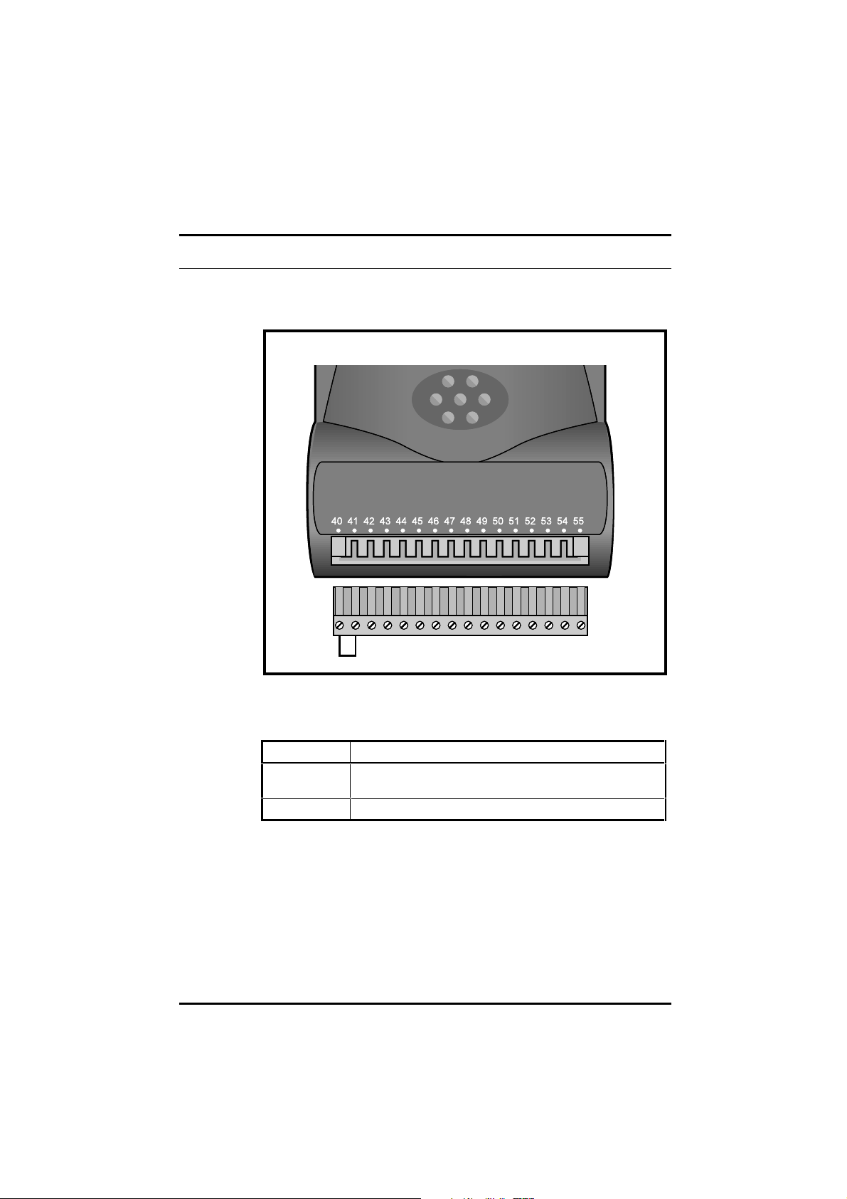
Figure 2 Location of the plug-in terminal block on the UD55
4.2 Functions of the terminals
Terminal Function
40
41
42 to 55 No connection
UD55 User Guide
Issue code: 55nu3
To enable the save function, terminals 40 and 41 should be directly
connected together
7
Page 12

5 Saving Parameters
If the Drive trips and a trip code is displayed while this procedure is being
followed, refer to Appendix A, Diagnostics. Ensure that all the required
parameters have been set up in the source Drive and that new parameter
values have been saved.
If a small option module was fitted in the Drive, its assoc iated Menu 16
parameters will be copied to the UD55 in addition to the parameters in the
other menus.
1 Insert the UD55 in the source Drive (refer to Chapter 3, Inserting the
UD55 in a Drive).
2 Ensure terminal 30 of the Drive Signal connector is open-circuit so that
the Drive does not become enabled when powered-up.
3 On the UD55 connector, connect terminal 40 directly to terminal 41 to
enable the save function (see Figure 2).
4 Re-fit the terminal cover to the Drive.
5 Connect the AC supply to the Drive.
6 Decide which parameter-set number is to be used in the UD55. If a
parameter-set already contains parameter values, these will be
over-written without warning. It is recommended that a record is
made of at least the following for each parameter-set number:
• A means of identifying the configuration of the source Drive
• The model size of the source Drive
• The type(s) of option module(s) fitted
• Motor ratings
7 Set parameter .00 (in any menu) at 300X, where X is the required
parameter-set number (1 to 8).
8 Press . The parameter values are now copied (saved) to the
UD55.
Saving takes approximately 5 seconds. When it has finished,
parameter .00 returns to zero.
9 It is recommended that parameter 11.38 is set at the number of the
parameter-set (value of
UD55 full parameter check sum noted, as a means of identifying the
parameter-set at a later date.
10 Disconnect the AC supply from the Drive.
8
X in step 7) and the value of parameter 11.40
UD55 User Guide
Issue code: 55nu3
Page 13

11 Remove the terminal cover.
12 Disconnect the link between terminals 40 and 41 on the UD55
connector.
13 Remove the UD55 from the Drive.
14 If a small option module was previously fitted in the Drive, re-fit the
module.
15 Replace the terminal cover.
16 The Drive can now be used.
UD55 User Guide
Issue code: 55nu3
9
Page 14

6 Loading Parameters
6.1 Loading a Parameter-set from the UD55
If the Drive trips and a trip code is displayed while this procedure is being
followed, refer to Appendix A, Diagnostics.
1 Ensure the destination Drive is configured in the same operating mode
as the source Drive. (The UD55 cannot change the operating mode of
the Drive.)
2 Ensure terminals 40 and 41 on the UD55 are not connected.
3 Insert the UD55 in the source Drive.
4 Ensure terminal 30 of the Drive Signal connector is open-circuit so that
the Drive does not become enabled when powered-up.
5 Re-fit the terminal cover to the Drive.
6 Connect the AC supply to the Drive.
7 It is recommended that the following is performed:
• Set parameter 11.38 at the number of the parameter-set to be used.
• Note the value of 11.40 UD55 full parameter checksum.
• Compare this value against the value noted when the parameter-set
was saved in the UD55.
If the values differ, this indicates that a different parameter-set has
been selected or the values contained in the parameter-set have been
changed.
8 Set parameter .00 (in any menu) at 400X, where X is the parameter-set
number of the configuration to be loaded in the destination Drive.
10
9 Press . The parameter values are now copied from the UD 55
(loaded) to the Drive. (If the operating mode of the destination
differs from that of the source, parameter values will not be loaded
and the Drive will trip; the display will indicate
Loading is almost instantaneous. Parameter .00 returns to zero.
10 Set parameter .00 at 1000 and press in order to save the
parameter values.
11 Disconnect the AC supply from the Drive.
12 Remove the terminal cover.
FSH.TYP).
UD55 User Guide
Issue code: 55nu3
Page 15

13 Remove the UD55 from the Drive; if no other small option module is
required in the Drive, the UD55 can remain perman ently fitted.
14 If required, fit a small option module.
15 Replace the terminal cover. The Drive can n ow be used.
6.2 Transferring parameter-sets between
Drives of different ratings
Values of certain motor parameters are not scaled correctly
when the current or voltage rating of the destination Drive
differs from that of the source Drive. For safety, refer to
Warning
the next instruction.
When transferring a parameter-set between Drives of different current or
voltage rating a FSH.rng trip will occur. All parameters will be copied
except those below:
• 2.08 Standard ramp voltage
• 4.05 – 4.07 Current limits
• 4.08 Torque reference
• 4.09 Torque offset
• 5.07 Motor – rated current
• 5.09 Motor – rated voltage
• 5.17 Stator Resistance
• 5.18 Switching frequency
• 5.24 Motor leakage inductance
• 5.33 Thermal model enable
• 6.06 D.C. injection braking current
• 15.07 Regen unit voltage setpoint
These parameters will need to be manually entered into the destinatio n
Drive if the trip occurs.
Note
UD55 User Guide
Issue code: 55nu3
With software versions before V03.xx.07, no trip will
occur and all parameters will be copied. The above
parameters should be manually entered into the
destination Drive and any other parameters that need to
be set up for the application.
11
Page 16

6.3 Using the UD55 with other small option modules
When a UD55 is fitted to the Drive it replaces any small option m odule that
may have been fitted previously. If parameters were last saved in the Drive
with a small option module fitted, other than a UD55, then m enu 16 will be
present and visable via the keypad when a UD55 is subsequently fitted. (If
no option module is fitted menu 16 will not be visable.) Therefore menu 16
parameters previously saved for the small option module can be transferred
to/from the UD55. To prevent incorrec t Drive operation, bec ause the
option module is not present, the Drive cannot be enabled when a UD55 is
fitted and the Drive contains a parameter set for a small option module.
These parameters can be removed from the Drive by saving parameters
with no small option module fitted.
Note
With software versions prior to V03.xx.07, it is possible to
enable a Drive with the UD55 fitted and Menu 16 present.
Terminal 30 of the Drive Signal connector must be opencircuit to prevent incorrect Drive operation when using
the UD55.
6.4 Avoiding problems with inter-related parameters
The maximum values of some parameters depend on other parameters, i.e.
the current limits (04.05 – 04.07) depend on the rated current (05.07).
With software versions before V03.xx.07 the parameter values for the
dependent parameters, i.e. in this case the current limits, may not be correct
after they are transferred from a UD55 to the Drive. A second tran sfer from
the UD55 to the Drive will give the correct values. With software versions
V03.xx.07 and onwards the parameters are automatically transferred twic e
from the UD55, and so the resulting values in the Drive will always be
correct.
12
UD55 User Guide
Issue code: 55nu3
Page 17

7 Erasing the entire flash memory of the UD55
1 Ensure terminals 40 and 41 on the UD55 are connected.
2 Insert the UD55 in a Drive (refer to Chapter 3, Inserting the UD55 in a
Drive).
3 Ensure terminal 30 of the Drive Signal connector is open-circuit so that
the Drive does not become enabled when powered-up.
4 Re-fit the terminal cover to the Drive.
5 Connect the AC supply to the Drive.
6 Set parameter .00 (in any menu) at 3099. All the parameter values are
now erased from the UD55.
Erasing takes from 2 to 14 seconds. When it is completed,
parameter .00 returns to zero.
7 Disconnect the AC supply from the Drive.
8 Remove the terminal cover (refer to Chapter 3, Inserting the UD55 in a
Drive).
9 Remove the UD55 from the Drive.
10 If a small option module was previously fitted in the Drive, re-fit the
module.
11 Replace the terminal cover. The Drive can n ow be used.
UD55 User Guide
Issue code: 55nu3
13
Page 18

8 Related parameters
(Not applicable to the Commander GP Drive)
Use parameters 11.38 and 11.39 find the operating mode for a particular
parameter-set, or to find if a parameter-set is empty.
11.38 UD55 parameter-set selector
ô
(See below)
Range
UD55 fitted 1 ~ 8
UD55 not fitted 0
Use 11.38 to select a parameter-set in the UD55.
11.39 UD55 operating-mode indicator
ô
OPEN.LP
CL.VECt
SErVO
rEGEn
FrEE
11.39 indicates the operating mode related to the parameter-set selected
in 11.38. When the selected parameter-set contains no values, 11.39
indicates FrEE.
ð
0 RWUni P
ð
0
1
2
3
4
RO Uni P
14
11.40UD55 full parameter checksum
ô
0 ~ 16383
When parameter values are copied to the UD55, a check sum is calcu lated
from all the parameter values. 11.40 contains the value of the checksum of
the parameter values contained in the parameter-set selected in 11.38.
ð
RO Uni P
UD55 User Guide
Issue code: 55nu3
Page 19

A Diagnostics
A.1 Trip Codes
The following trip codes are associated with the UD55.
Drive
display
FSH.Err 182
The UD55 memory has been found to be corrupt. If the trip has been produced at
power-up then the memory of the UD55 is automatically reformatted and all
parameter-sets are erased. If errors are detected after power-up, the trip will occur
but the memory of the UD55 will not be reformatted automatically.
FSH.DAt 183
No values in the selected parameter-set; no values are copied to the
destination Drive.
FSH.TYP 184
The operating mode of the destination Drive differs from that related to the
parameter-set; no parameter values are copied to the destination Drive. Either
select an appropriate parameter-set, or change the operating mode of the
destination Drive.
FSH.ACC 185
Write access to the UD55 has not been enabled (terminal 40 not connected to 41 );
no parameter values are copied to the UD55.
FSH.LO 186
The parameter-set contains values for Menu 20 parameters, but a large option
module is not fitted in the destination Drive. Values of Menu 20 parameters are not
copied to the destination Drive.
FSH.20 187
The parameter-set does not contain values for Menu 20 parameters, but a large
option module is fitted in the destination Drive. Values of Menu 20 parameters are
not copied to the destination Drive.
FSH.rng 188
The current or voltage rating of the destination Drive differs from that related to the
parameter-set in the UD55. Parameters are copied except for those listed in
Section 6.2 of this User Guide.
No. Conditions
UD55 User Guide
Issue code: 55nu3
A-1
Page 20

A-2
UD55 User Guide
Issue code: 55nu3
 Loading...