

Page 1

User Guide
UD52UD52
SIN-COS encoder
interface
small option module
for Unidrive
Part Number: 0460 - 0085
Issue Number: 3
Page 2

General Information
The manufacturer accepts no liability for any consequences resulting from
inappropriate, negligent or incorrect installation or adjustment of the
operating parameters of the equipment or from mismatching the Drive
with the motor.
This option module is intended for use only with Control Techniques
Unidrive products. Any other use invalidates the warranty and may cause a
safety hazard.
The contents of this Guide are believed to be correct at the time of
printing. In the interests of a commitment to a policy of continuous
development and improvement, the manufacturer reserves the right to
change the specification of the product or its performance, or the
contents of this Guide, without notice.
All rights reserved. No part of this Guide may be reproduced or
transmitted in any form or by any means, electrical or mechanical including
photocopying, recording or by any information storage or retrieval system,
without permission in writing from the publisher.
Use within the European Union, etc
The following information applies where the end use of the Drive is within
the European Union, the European Economic Area, or other regions which
have implemented Directives of the European Council or equivalent
measures.
The Drive, together with its associated option modules, complies with the
Low Voltage Directive 73/23/EEC.
The installer is responsible for ensuring that the equipment into which the
Drive is incorporated complies with all relevant Directives.
The complete equipment must comply with the EMC Directive 89/336/EEC.
If the Drive is incorporated into a machine, the manufacturer is responsible
for ensuring that the machine complies with the Machinery Directive
89/392/EEC. In particular, the electrical equipment should generally
comply with European Harmonised standard EN60204-1.
Copyright © January 2002 Control Techniques Drives Ltd
Issue Code: 52nu3
Page 3

Contents
Chapter
1 Introduction 1
1.1 Main features of the UD52 1
1.2 Principle of operation 2
2 Safety Information 3
3 Installing the UD52 6
4 Making Connections 8
4.1 Locations of the terminals 8
4.2 Functions of the terminals 9
4.3 Serial communications 11
5 Setting Up the UD52 12
5.1 Initial setting up 12
5.2 Phase offset 12
5.3 Position information 13
5.4 Simulated-encoder outputs (terminals 50, 51, 53, 54) 15
5.5 Freeze inputs (terminals 48, 49) 16
5.6 Further setting up 16
6 Related Parameters 17
6.1 Introduction 17
6.2 Programmable software 17
6.3 Parameter descriptions 19
Appendix
A Specifications A-1
A.1 Inputs and outputs A-1
B Advanced Functions B-1
B.1 Alternative configurations B-1
B.2 Aligning the encoder mechanically B-2
C Diagnostics C-1
C.1 Trip codes C-1
UD52 User Guide
Issue code: 52nu3
Page 4

UD52 User Guide
Issue code: 52nu3
Page 5

1 Introduction
1.1 Main features of the UD52
Note
The UD52 can be used only with Drives equipped with
version 3 (or later) software. (Parameter 0.50 indicates
the software version.)
ApplicationsThe UD52 SIN-COS encoder small option module is an interface module for
installation in a Unidrive. The UD52 operates with encoders havin g 256,
512, 1024, 2048 or 4096 lines per revolution, and has a maximum operating
frequency of 102.4kHz (3000RPM with a 2048-line encoder).
The UD52 can be used in a Drive operating in either the Closed-lo op Vector
or Closed-loop Servo mode in order to obtain speed feedbac k and very
high resolution shaft position. The UD52 is fully co mpatible with the
following Stegmann
SCS60, SCM60, SCS70, SCM70
These encoders are compatible with the two-wire serial com munic ations
port in the UD52.
Absoluteposition
information
Selection of
encoder
function
Simulated
encoder
outputs
InstallationThe UD52 must be fitted in the small option module bay of the Unidrive.
The UD52 can determine the absolute position within a revolutio n of a
single-turn encoder, or in many revolutions of a multi-turn encoder. Unlike
the case for a standard encoder, which must be rotated past its marker
pulse in order to obtain absolute-position information, absolute-position
information from a (suitable) SIN-COS encoder is obtained when the Drive is
powered-up.
Speed and position information is displayed in parameters which can be
read on the Drive display and/or via serial communications.
When a UD52 is fitted in the Drive, the Drive automatically uses the SIN-COS
encoder as speed and position feedback for the motor. Alternatively, a
standard quadrature encoder can be used for speed and position feedback,
and the SIN-COS encoder used as an incremental reference.
The UD52 has simulated encoder outputs which normally use the SIN-COS
encoder as the source, but can be reconfigu red to use the main encoder
(Encoder 1) connected to the 15-way D-type on the Drive as the source.
These outputs produce quadrature A/B signals correspondin g to the line
counts from the source encoder. Also, these outputs can be configured for
frequency and direction (F/D) signals.
All connections to the Drive are made by a multi-way connector.
Connections from external equipment are made by a pluggable 16-way
screw-terminal block on the UD52.
SIN-COS encoders:
UD52 User Guide
Issue code: 52nu3
1
Page 6

1.2 Principle of operation
The UD52 converts the sinusoidal output signals of a SIN-COS encoder into
square waves and counts the edges (as in the case of a standard encoder) to
yield position counts at a rate of four times the number of lines per
revolution of the encoder. The constantly varying amplitudes of the sine
waves are also measured by the UD52 in order to produce 211 (2048)
interpolated counts between encoder lines.
The overall resolution is the product of the number of interpolated counts
and the number of encoder lines. For example, the UD 52 used with a
512-line (2
revolution).
9
) encoder can give a resolution of 220 (1 048 576) counts per
UD52 User Guide
2
Issue code: 52nu3
Page 7

2 Safety Information
2.1
Warnings, Cautions and Notes
A Warning contains information which is essential for avoiding a safety
hazard.
A Caution contains information which is necessary for avoiding a risk of
damage to the product or other equipment.
A Note contains information which helps to ensure correct operation of the
product.
2.2 Electrical safety –
general warning
The voltages used in the Drive can cause severe electric sho ck and/or burns,
and could be lethal. Extreme care is necessary at all times when working
with or adjacent to the Drive.
Specific warnings are given at the relevant places in this User Guide.
The installation must comply with all relevant safety legislation in the
country of use.
The Drive contains capacitors that remain charged to a poten tially lethal
voltage after the
energized, the AC supply must be isolated at least ten minutes before work
may continue.
AC supply has been disconnected. If the Drive has been
2.3 System design
The Drive is intended as a component for professional incorporation into
complete equipment or systems. If installed in correctly the Dr ive may
present a safety hazard. The Drive uses high voltages and currents, carries
a high level of stored electrical energy, and is used to control m echanical
equipment which can cause injury.
Close attention is required to the electrical installation and the systemdesign to avoid hazards either in normal operation or in the event of
equipment malfunction. System-design, installation, commissioning and
maintenance must be carried out by personnel who have the necessary
training and experience. They must read this safety information and this
User Guide carefully.
To ensure mechanical safety, ad ditional safety devic es such as
electro-mechanical interlocks m ay be required. The Dr ive must not be u sed
in a safety-critical application without additional high-integrity protection
against hazards arising from a malfunction.
UD52 User Guide
Issue code: 52nu3
3
Page 8

2.4 Environmental limits
Instructions in this User Guide regarding transport, storage, installation and
use of Drives must be complied with, including the specified environmental
limits. Drives must not be subjected to excessive ph ysical force.
2.5 Compliance with regulations
The installer is responsible for complying with all relevant regulations, such
as national wiring regulations, accident prevention regulations and
electromagnetic compatibility (EMC) regulations. Particular attention must
be given to the cross-sectional areas of conductors, the selection of fuses or
other protection, and protective earth (ground) connections.
The Unidrive Installation Guide contains instructions for achieving compliance
with specific EMC standards.
Within the European Union, all machinery in which this product is used must
comply with the following directives:
89/392/EEC: Safety of Machinery
89/336/EEC: Electromagnetic Compatibility
2.6 Safety of personnel
The STOP function of the Drive does not remove dangerous voltages from
the output of the Drive or from any external option unit.
The Stop and Start controls or electrical inpu ts of the Drive m ust not be
relied upon to ensure safety of personnel. If a safety hazard could exist
from unexpected starting of the Drive, an interlo ck that electric ally isolates
the Drive from the
inadvertently started.
Careful consideration must be given to the functions of the Drive which
might result in a hazard, either through their intended functions (eg.
Auto-start) or through incorrect operation due to a fault or trip (eg.
stop/start, forward/reverse, maximum speed).
Under certain conditions, the Drive can suddenly discontinue control of the
motor. If the load on the motor cou ld cause the moto r speed to be
increased (eg. hoists and cranes), a separate method of braking and
stopping the motor must be used (eg. a mechanical brake).
Before connecting the
understand the operating controls and their operation. If in doubt, do not
apply AC power to the Drive. Damage may occur, or lives put at risk.
Carefully follow the instructions in this User Guide.
Before making adjustments to the Drive, ensure all personnel in the area are
warned. Make notes of all adjustments that are made.
AC supply must be installed to prevent the motor being
AC supply to the Drive, it is important that you
UD52 User Guide
4
Issue code: 52nu3
Page 9

2.7 Risk analysis
In any application where a malfunction of the Drive could lead to damage,
loss of life or injury, a risk analysis must be carried out, and where necessary,
further measures taken to reduce the risk. This would normally be an
appropriate form of independent safety back-up system using simple
electro-mechanical components.
2.8 Signal connections
The control circuits are isolated from the po wer circuits in the Drive by basic
insulation only, as specified in IEC664–1. The installer must ensure that the
external control circuits are insulated from human contact by at least one
layer of insulation rated for use at the AC supply voltage.
If the control circuits are to be connected to other circuits classified as
Safety Extra Low Voltage (SELV) (eg. to a personal computer), an additional
isolating barrier must be included in order to maintain the SELV
classification.
2.9 Adjusting parameters
Some parameters have a profound effect on the operation of the Drive.
They must not be altered without careful consideration of the impact on
the controlled system. Measures must be taken to prevent un wanted
changes due to error or tampering.
UD52 User Guide
Issue code: 52nu3
5
Page 10

3 Installing the UD52
Before using the following procedure, refer to the
Warnings at the beginning of Chapter 2 Installing the Drive in
Warning
the Unidrive Installation Guide.
1 Ensure the Drive is operating in either the Closed-loop Vector or the
Closed-loop Servo mode (this is indicated by parameter 11.31 (0.48).
2 Before installing the UD52 in the Unidrive, ensure the AC supply has
been disconnected from the Drive for at least 10 minutes.
3 Check that the exterior of the UD52 is not damaged, and that the
multi-way connector is free from dirt and debris. Do not install a
damaged or dirty UD52 in the Drive.
4 Remove the terminal cover from the Drive (for removal instructions,
see Installing the Drive in Chapter 2 of the Unidrive Installation Guide).
5 Position the multi-way connector on the rear of the UD52 over the
connector in the Drive (see Figure 1), and press on the thumb pad to
push the UD52 into place.
6 Re-fit the terminal cover to the Drive.
7 Connect the AC supply to the Drive.
8 Set parameter .00 at 149 to unlock security.
9 Check that Menu-16 parameters are now available.
10 Check that parameter 16.01 is set at 4.
11 If the checks in steps 8 and 9 fail, perform the following:
• Remove the
• Wait at least 10 minutes.
• Remove the terminal cover.
• Check that the UD52 is fully inserted.
• Replace the terminal cover.
• Re-apply the
• Check again that parameter 16.01 is set at
AC supply from the Drive.
AC supply.
4.
UD52 User Guide
6
Issue code: 52nu3
Page 11
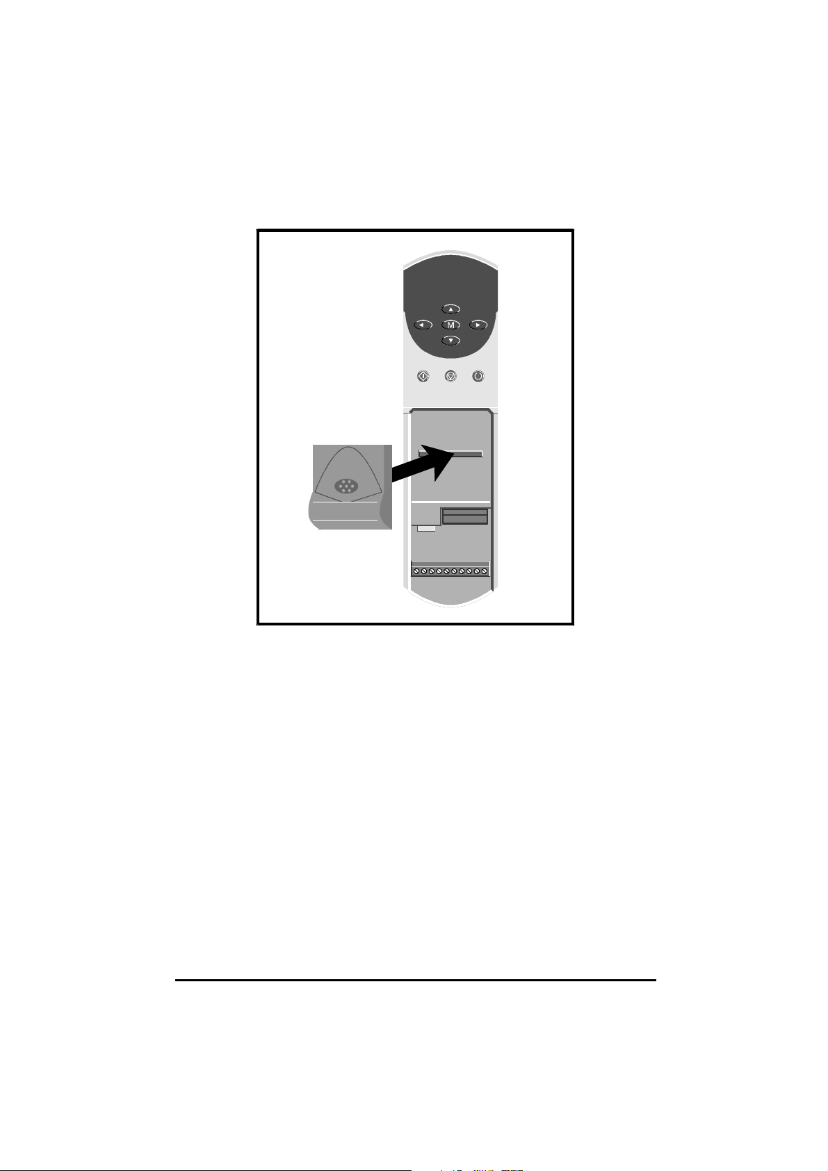
Figure 1 Installing the UD52 in the Unidrive
UD52 User Guide
Issue code: 52nu3
7
Page 12
4 Making Connections
The control circuits are isolated from the power circuits in
the Drive by basic insulation only, as specified in IEC664–1.
The installer must ensure that the external control circuits
Warning
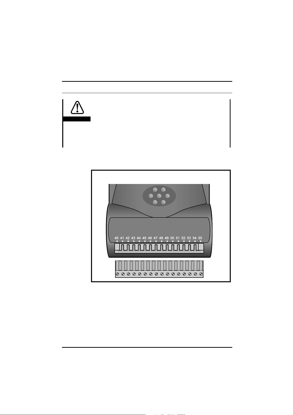
4.1 Locations of the terminals
are insulated from human contact by at least one layer of
insulation rated for use at the
If the control circuits are to be connected to other circuits
classified as Safety Extra Low Voltage (SELV) (eg. to a
personal computer), an additional isolating barrier must be
included in order to maintain the SELV classification.
AC supply voltage.
Figure 2 Location of the two-part terminal block
8
UD52 User Guide
Issue code: 52nu3
Page 13

4.2 Functions of the terminals
(Note that \ indicates not (eg. F\ indicates not F)
Terminal Name Function Comments
40 SININ Sine input signal Always required
41 SINREF Sine input reference
42 COSIN Cosine input signal
43 COSREF Cosine input reference
44 0V 0V common
45 +VENC DC supply to encoder
46 SC DATA Serial comms. EIA485 input and output
47 SC DATA\ Serial comms. EIA485 input and output
48 FREEZE Freeze SC DATA input Optional
49 FREEZE\ Freeze SC DATA\ input
50 A
(F)
51 A\
(F\)
52 0V 0V common
53 B
(D)
54 B\
(D\)
55 0V 0V common
Simulated-encoder
phase quadrature output A
or frequency output F
(EIA485 serial link)
Simulated-encoder
phase quadrature output A\
or frequency output F\
(EIA485 serial link)
Simulated-encoder
phase quadrature output B
or direction output D
(EIA485 serial link)
Simulated-encoder
phase quadrature output B\
or direction output D\
(EIA485 serial link)
Use for Closed-loop
Servo mode or
when absolute position
is required
Optional
UD52 User Guide
Issue code: 52nu3
9
Page 14

SIN
COS
Main feedback
SIN-COS
encoder
Figure 3 Standard wiring configuration
SCDATA
Sine
output
Cosine
output
0V
+V
Serial
comms.
SIN-COS encoder
SININ
SINREF
COSIN
COSREF
0V
+VENC
SCDATA
SCDATA\
UD52
Figure 4 Grounding and screening recommendations for the UD52
The sinusoidal signals from a
SIN-COS encoder are low-voltage analog signals.
Ensure that electrical noise from the Drive o r motor do es not adversely
affect the encoder feedback. Ensure that moto r cables are shielded (see
Chapter 2 Installing the Drive in the Installation Guide). Refer to Figure 3 for
grounding and screening recommendations for the UD52.
For the simulated encoder connections, refer to the instructions for the
equipment that is to receive the signals.
UD52 User Guide
10
Issue code: 52nu3
Page 15

4.3 Serial communications
When absolute positioning is required, connect terminals 46, 47 Serial
communications to the appropriate connections on the encoder.
The serial link allows the Drive (at power-up) to interrogate the
encoder in order to determine the initial absolute position of the encoder
shaft. When the interrogation is completed, the serial link is disabled.
If the serial link fails, the Drive will trip, showing trip code
When a
SIN-COS encoder is used with a Drive operating in the Closed-loop
Servo mode, absolute-position and phase-offset information is always
required. In the Closed-loop Vector mode for controlling an induction
motor, absolute-position and phase-offset information are optional.
When this information is not required, serial communications connections to
the encoder do not need to be made. In this case, set parameter 16.16
S
IN-COS encoder – serial comms disable at 1 (otherwise a SEP EC trip will occur
at power-up).
SIN-COS
SEP EC.
Operating mode Terminals
Closed-loop Servo mode
Closed-loop Vector mode when absolute-position
information is required
Closed-loop Vector mode when absolute-position
information is not required
Parameter
46, 47
Connect to serial comms. port
SIN-COS encoder
of
No connections 1
16.16
0
UD52 User Guide
Issue code: 52nu3
11
Page 16

5 Setting Up the UD52
The instructions in this chapter apply when the Drive is being set up for the
first time with a UD52 fitted.
5.1 Initial setting up
The default supply voltage to the encoder from terminal 45 is +5.15V. If the
encoder requires 8V, set parameter 16.15 SIN-COS encoder– voltage select
at 1.
Enter the number of lines per revolution for the
parameter 16.12 SIN-COS encoder – No. of lines per revolution. The value can
be only a power of 2.
5.2 Phase offset
When the Drive is operating in the Closed-loop Servo mode, the phaseoffset of the SIN-COS encoder in relation to the mo tor shaft must be
entered in parameter 16.09 SIN-COS encoder – phase offset.
The phase offset can be entered in either of the following ways:
• Performing an encoder phasing test. The UD52 measures the phase
error automatically and enters the value in 16.09.
• If the phase offset is known, you can enter the value manually in
parameter 16.09.
See also Aligning the encoder mechanically in Appendix B Advanced functions.
Encoder phasing test (Closed-loop Servo mode)
SIN-COS encoder in
Warning
12
During the phasing test, the motor shaft rotates slowly.
Before starting, make sure it will be safe for the motor to
be run.
During the phasing test, the motor shaft rotates in two stages, as follo ws:
1
• Initial jump in position by
• Subsequent rotation by
Where
N is the number of motor poles.
revolution
N
4
revolution
N
Examples
No. of poles Initial jump Subsequent rotation
2
6
1
revolution 2 revolutions
2
1
revolution
6
2
revolution
3
UD52 User Guide
Issue code: 52nu3
Page 17

Procedure
1 Ensure the motor is unloaded (any load will create errors in the
phase-offset measurement).
2 Set parameter 16.10 SIN-COS encoder phasing test at 1.
3 Enable the Drive.
The motor shaft rotates (as described above) and the measured value of
phase offset is automatically entered in parameter 16.09 S
phase offset.
If a phasing test is attempted with a motor that has any of the following...
• High inertia
• No damping
• Small load on the shaft
...an incorrect value for the phase offset will be measured. Refer to
parameter 5.27 in the Unidrive Advanced User Guide.
Note
If the Drive trips and the display indicates trip code
ENC.PH7, this indicates either of the following:
The
SIN and COS input connections from the
encoder are incorrectly made
The phase sequence of the motor is reversed
After correcting the connections, repeat the procedure.
Magnetizing current test (Closed-loop Vector)
IN-COS encoder –
Refer to Autotune in Chapter 3 Setting Up the Drive in the Unidrive User Guide,
or to parameter 5.12 in the Unidrive Advanced User Guide. If the Drive trips
while Autotune is being performed see the Note above.
5.3 Position information
Counting revolutions
Single-turn encoder
Revolutions are not counted.
Multiple-turns encoder
Revolutions are indicated in parameter 16.03 S
count. When the serial communications link to the encoder is used, at
power-up the value stored in the encoder is transferred to 16.03. When
the value of 16.03 reaches a maximum limit that is defined in parameter
16.13 SIN-COS encoder – No. of revolutions, 16.03 is reset and the count
starts again from zero.
UD52 User Guide
Issue code: 52nu3
IN-COS encoder – revolution
13
Page 18

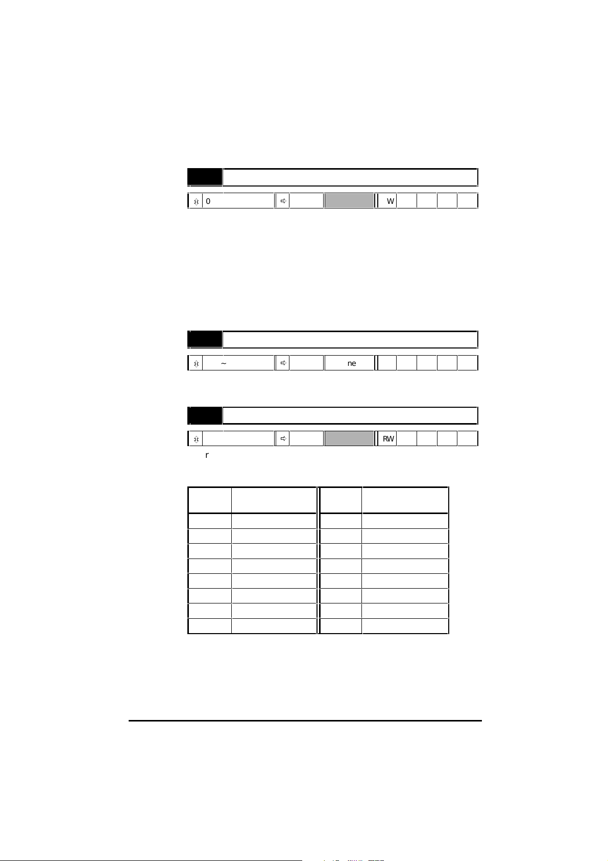
By default, 16.03 will not count. When a multi-turn encoder is used, enter
the required value in 16.13, as follows:
16.13 16.03 counts up
to...
008255
119511
2 3 10 1023
37112047
415124095
531138191
6631416383
71271532767
Absolute-position parameters
When the following conditions are met...
• A compatible
connections are made
• 16.16 S
• 16.14 S
...the absolute position is indicated by the following parameters:
16.04 S
16.05
IN-COS encoder – serial comms. disable is set at 0 (default)
IN-COS as reference encoder is set at 0 (default)
IN-COS encoder incremental position (coarse)
SIN-COS encoder incremental position (fine)
16.13 16.03 counts up
to...
SIN-COS encoder is used and serial communications
14
UD52 User Guide
Issue code: 52nu3
Page 19

Using position information for orientation
The position value in parameter 16.04 SIN-COS encoder incremental position
(coarse) (at 16384 counts per revolution) is used as an input to the position-
control algorithms in Menu 13. This allows orientation to be performed
within one revolution.
Using position information for digital lock
The digital-lock algorithm uses only incremental changes in position
obtained from parameter 16.04 and ignores the multi-turn information in
parameter 16.03 SIN-COS encoder – revolution count.
Only incremental digital lock is performed; multi-turn absolute orientation is
not supported.
5.4 Simulated-encoder outputs
(terminals 50, 51, 53, 54)
The simulated-encoder outputs can be connected to external equipment for
monitoring the output of either a SIN-COS encoder connected to the UD52
or the main encoder (Encoder 1) that is connected to the 15-way D-type on
the Drive. By default, the SIN-COS encoder is used as the source. To select
Encoder 1, set parameter 16.06 Simulated-encoder output select at 1.
Quadrature AB, or frequency and direction
By default, the simulated-encoder outputs are phase-quadrature A and B
signals. For frequency (F) and direction (D) signals, set parameter 16.08
Simulated encoder – F/D output enable at 1.
Pulses per revolution
The simulated-encoder outputs are derived from the polarity changes in the
SIN-COS encoder outputs, giving a resolution of four times the number of
encoder lines per revolution.
The number of pulses per revolution (
lines per revolution of the SIN-COS encoder as well as on the value 16.07
Simulated-encoder output scaling.
By default, the outputs are scaled 1:1 . To chan ge the scaling, enter the
required value in parameter 16.07 Simulated-encoder output scaling. The
scaling factor is given by the following:
1
1607[.]
2
UD52 User Guide
Issue code: 52nu3
PPR) is dependent on the number of
15
Page 20

5.5 Freeze inputs
(terminals 48, 49)
If the Freeze function is required, a UD70 large option module must be fitted
in the Drive in order to read the freeze position, and pass the data to the
system controller or PLC. The initiating signal for the freeze function must
be applied to terminals 48 and 49 on the UD52.
Related UD70 parameters
_Q20%.5 Control word (bit 5)
Set at 1 for the current absolute positions of the feedback and reference
encoders to be entered in _Q21% and _Q22% when the Freeze input is
activated.
_Q20%.5 is reset to zero when the values have been entered.
_Q21% Feedback-encoder freeze value
Units Encoder lines
Range –231 to 2
Reset H = S/V S = N/A P = N/A
_Q22% Reference-encoder freeze value
Units Encoder lines
Range –231 to 2
Reset H = S/V S = N/A P = N/A
31
31
5.6 Further setting up
Refer to Parameters descriptions in Chapter 6 Related Parameters for setting
up the following:
Disable interpolation 16.17
Disable updating the position parameters when reading 16.11
16
Function Parameter
UD52 User Guide
Issue code: 52nu3
Page 21

6 Related Parameters
6.1 Introduction
The parameters listed in this chapter are used for programming and
monitoring the UD52. Refer to the Unidrive User Guide for programming
instructions.
Before attempting to adjust any parameters, refer to the
Warnings and Notes at the beginning of Chapter 3 Setting up
Warning
6.2 Programmable software
Key
the Drive in the Unidrive User Guide.
Type of parameter
RO Read-only
RW Read–write
...select Select from two settings
...enable Make or allow a function to operate
...disable Stop or disallow a function from operating
...indicator The value can only be read
Limitations of use
S The new parameter-value is saved when the
disconnected from the Drive.
P Protected parameter; the parameter cannot be used as the
destination parameter for a programmable input.
Range
Bi Variable parameter having bipolar value range.
Uni Variable parameter having unipolar value range.
Bit Bit parameter
Symbols
ð
Default value
ô
Range of values
~ Indicates a range of values
(in the case of bit parameters, ~ indicates or).
AC supply is
UD52 User Guide
Issue code: 52nu3
17
Page 22

SIN-COS encoder −
16.12
No. of lines per
revolution
SIN-COS encoder −
16.13
SININ
40
41
SINREF
COSIN
42
43
COSREF
SIN-COS encoder
phase offset
SIN-COS encoder
Encoder 1
position
phasing test
No. of revolutions
SIN-COS as
16.14
reference encoder
SIN-COS encoder
16.15
voltage
select
SIN-COS encoder −
16.16
serial comms. disable
16.09
16.10
3.27
Simulated-encoder
output
select
Figure 5 Logic diagram for the UD52
16.06
SIN-COS encoder
16.11
update
16.02
SIN-COS encoder
RPM
1
[16.07]
2
16.07
Simulated-encoder
output scaling
disable
16.03
SIN-COS encoder
revolution count
16.04
SIN-COS encoder
incremental
position (coarse)
16.05
SIN-COS encoder
incremental
position (fine)
Simulated encoder
F/D output enable
16.08
A (f)
A\ (f\)
B (D)
B\ (D\)
50
51
53
54
18
UD52 User Guide
Issue code: 52nu3
Page 23

6.3 Parameter descriptions
16.01 Option module fitted code
ô
0 ~ 100
16.01 indicates the type of small option module that is fitted in the D rive,
as follows:
0 No small option module
1 UD50 Additional I/O
2 UD51 Second encoder interface
3 UD53 Resolver interface
4UD52
SIN-COS encoder interface
16.02SIN-COS encoder RPM
ô
±30 000
16.02 indicates the speed of rotation of the encoder. This depends on the
correct value having been entered in 16.12 SIN-COS encoder – No. of lines per
revolution.
16.03SIN-COS encoder – revolution count
ô
0 ~ 32767
When a multiple-turns encoder and an appropriate value has been entered in
16.13 SIN-COS encoder – No. of revolutions, 16.03 indicates the absolute
position. In other cases, 16.03 indic ates relative position.
When the Drive is powered-up and the serial communications link is used,
the value of 16.03 is set at the value stored in the encoder. The value
increases to a maximum value determ ined by the setting of param eter
16.13 S
IN-COS encoder – No. of revolutions. On the following revolution, the
value of 16.03 returns to zero ready to count up again.
ð
ð
ð
RO Uni P
RPM RO Bi P
Revolutions RO Uni P
16.04 indicates the absolute position of the moto r shaft. This position
information is derived by the UD52 counting the changes in sign of the
encoder outputs, some of the interpolated information and the initial
position information.
See 16.05 S
UD52 User Guide
Issue code: 52nu3
16.04SIN-COS encoder – incremental position (coarse)
ô
0 ~ 16383
IN-COS encoder – incremental position (fine).
ð
rev/16384 RO Uni P
19
Page 24

16.05SIN-COS encoder – incremental position (fine)
ô
0 ~ 255
ð
rev/4194304 RO Uni P
16.04 and 16.05 indicate the position of the motor shaft to a resolu tion
given by:
256 1604 1605
××++[.][.]
((
))
4194304
revolution
When the number of encoder lines is less than 2048 (see 16.12), 16.05
indicates the following increments:
No. of lines 16.05 increment Available resolution
256 8 524288
512 4 1048576
1024 2 2097152
2048 1 4194304
4098 1 4194304
The least significant digit is not available
16.06 Simulated-encoder output select
ô
0 ~ 1
The simulated encoder outputs appear on the following terminals:
ð
0 RW Bit
20
Terminal Name
50 A (F)
51 A\ (F\)
53 B (D)
54 B\ (D\)
Set 16.06 to select the source of the simu lated encoder ou tputs as follows:
16.06 Source
0SIN-COS encoder
1Encoder 1
The simulated encoder outputs are derived only from the counted sign
reversals of the source encoder and do not include interpolation. No zeropulse information is produced.
UD52 User Guide
Issue code: 52nu3
Page 25

16.07Simulated-encoder output scaling
ô
0 ~ 15
ð
02
n
RWUni
Enter the required value in 16.07 for scaling the simulated-encoder output.
The scaling factor is as follows:
1
1607[.]
2
16.08 Simulated encoder– F/D output enable
ô
0 ~ 1
ð
0 RW Bit
Use 16.08 to select the output mode of term inals 50, 51, 53, 54, as follows:
16.08 Output mode
0 A/B quadrature signals
1 Frequency and direction signals
16.09SIN-COS encoder– phase offset
ô
0 ~ 6143
16.09 indicates the value of phase offset. See Phase offset in Chapter 5
Setting up the UD52 for ways in which the value is entered.
The value is saved at power-down and is changed only when one of the
procedures in Phase offset is performed.
When the operating mode of the Drive is changed, 16.09 i s reset to zero.
Restoring default values does not affect the value of 16.09.
ð
1/6143 rev. RWUni S P
Set 16.10 at 1 to initiate the encoder phasing test (on com pletion, 16.10
automatically returns to 0). See Phase offset in Chapter 5 Setting up the
UD52.
UD52 User Guide
Issue code: 52nu3
16.10SIN-COS encoder phasing test
ô
0 ~ 1
ð
0 RW Bit
21
Page 26
16.11 SIN-COS encoder update disable
ô
0 ~ 1
ð
0 RW Bit
When 16.11 is set at 0 (default), and the SIN-COS encoder shaft position is
being read from parameters 16.03, 16.04 and 16.05 by a large option
module (eg. UD70) or via serial communications, the values of these
parameters are free to change during the read process. This can result in
large position-errors being read.
To ensure that the position information from all three parameters is
consistent when reading the values, set 16.11 at 1 to hold the three
parameters at the last complete set of values. When the read proc ess is
completed, return 16.11 at 0 to allow the parameter values to contin ue to
be updated.
16.12SIN-COS encoder – No. of lines per revolution
ô
256 ~ 4096
ð
512 lines RWUni
Enter the number of lines per revolution of the SIN-COS encoder being used.
The value can only be a power of 2.
16.13 SIN-COS encoder – No. of revolutions
ô
0 ~ 15
Enter the required value to give the number of revolutio ns that parameter
16.03 SIN-COS encoder – revolution count is to count to before being reset.
The entered value must be the required power of 2, as follows:
ð
0 RWUni
22
16.13 16.03 counts up
to...
008255
119511
2 3 10 1023
37112047
415124095
531138191
6631416383
71271532767
16.13 16.03 counts up
to...
For use with a single-turn encoder, set 16.13 at 0.
UD52 User Guide
Issue code: 52nu3
Page 27

Caution
16.14SIN-COS as reference encoder
ô
0 ~ 1
ð
0 RW Bit
To use the SIN-COS encoder for speed and position reference, set 16.14 at 1.
See Alternative configurations in Appendix B Advanced functions.
16.15SIN-COS encoder– voltage select
ô
0 ~ 1
A 5V encoder can be damaged if it is supplied with 8V
ð
0 RW Bit
Use 16.15 to select the encoder
DC supply voltage from terminal 45,
as follows:
16.15 Voltage
0 +5.15V
1+8.0V
16.16 SIN-COS encoder– serial comms. disable
ô
0 ~ 1
ð
0 RW Bit
When the initial-position information is not required (or not available) from
the encoder, set 16.16 at 1 to disable the serial communications link. (See
Serial communications in Chapter 5 Setting Up)
16.17 SIN-COS encoder– interpolation disable
ô
0 ~ 1
Set 16.17 at 1 when the position information is to consist only of the basic
line count (without interpolation being obtained from the intermediate
values of the sine wave outputs of the encoder).
ð
0 RW Bit
UD52 User Guide
Issue code: 52nu3
23
Page 28

24
UD52 User Guide
Issue code: 52nu3
Page 29

A Specifications
A.1 Inputs and outputs
Inputs SININ, SINREF, COSIN, COSREF (terminals 40, 41, 42, 43)
Type Differential voltage
Signal level 1.1V peak-to-peak
Maximum input frequency 105kHz (not all SIN-COS encoders are designed to operate at this
maximum frequency)
Absolute maximum DC voltage
that can be applied
Input resistance 1kΩ ±5% (to 0V)
Encoder DC supply (VENC) (terminal 45)
Nominal voltage +5.15V or +8V
Tolerance ±3%
Maximum output current 300mA
Protection Protected against short-circuit and overload
Serial communications (terminals 46, 47)
±4V
Transceiver mode EIA485 2-wire master-slave
Bias resistors 1KΩ (If the inputs are not connected, the bias resistors will ensure
logic 1 is detected)
Termination resistor 120Ω ±5% (internal, no series capacitor)
Mode of operation Differential
Maximum permissible number of drivers on the serial link 32
Maximum cable length 1200m (4000 ft)
Maximum data rate (20kbps) 10Mbaud
Maximum-common mode voltage –7V ~ +12V
Driver output signal ±1.5V
Driver load 60Ω
Receiver input resistance >12kΩ
Receiver sensitivity ±300mV
within the common-mode
voltage range
UD52 User Guide
Issue code: 52nu3
A-1
Page 30

Freeze inputs (terminals 48, 49)
EIA485 differential (see terminals 46, 47)
Simulated-encoder outputs (terminals 50, 51, 53, 54)
Output type EIA 485
Maximum output frequency Quadrature: 205kHz
Frequency and direction: 410kHz
Output voltage Conforms to EIA 485
Absolute maximum voltage that can be applied to
each terminal
Protection Current limit with thermal protection
Output state Typical output voltage
relative to 0V
5mA load 25mA load
Low 1.0V 1.5V
High 4.5V 4V
–10V ~ +15V
0V common (terminals 44, 52, 55)
Absolute maximum current that can be applied
through each terminal
A-2
200mA
UD52 User Guide
Issue code: 52nu3
Page 31
B Advanced Functions
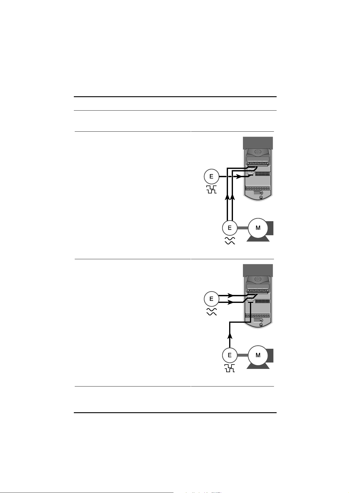
B.1 Alternative configurations
Reference: Quadrature encoder connected to the 15-way
D-type in the Drive
Main feedback: S
Refer to Menus 3, 13, 16
Reference: SIN-COS encoder connected to the UD52
Main feedback: Quadrature encoder connected to the
15-way D-type in the Drive
Refer to Menus 3, 13, 16
IN-COS encoder connected to the UD52
Reference
encoder
SIN
COS
Main feedback
SIN-COS
encoder
Reference
SIN-COS
encoder
SCDATA
SIN
COS
UD52 User Guide
Issue code: 52nu3
SCDATA
Main feedback
encoder
B-1
Page 32

B.2 Aligning the encoder mechanically
(Closed-loop Servo mode)
Note
Use this procedure only when the procedure described in
Phase offset in Chapter 5 Setting Up the UD52 cannot be
performed.
When the SIN-COS encoder is used as the feedback, use the following
procedure to precisely align the encoder with the mo tor (for zero
phase-offset). Precise alignment can be achieved only when the encoder is
connected to the Drive.
The Drive detects the exact points of polarity reversal of the (sine wave)
outputs. It would not be possible to identify these accurately on an
oscilloscope as in the case of standard encoders.
During this procedure, the motor shaft will be rotated
suddenly to a new position. Before starting, make sure it
will be safe for the motor shaft to be rotated.
Warning
1 Disconnect the motor from the Drive.
2 Ensure the shaft is unloaded and free to rotate.
3 Apply a direct current of 50% of the motor rated current through the
motor windings, as shown in Figure B–1.
Figure B–1 Connecting a motor to a DC source for mechanically aligning the
encoder shaft
The motor shaft will rotate to one of several positions depen ding on the
number of pole-pairs. For example, the shaft of a 6-pole motor will stop at
one of three places.
IN-COS encoder –
UD52 User Guide
Issue code: 52nu3
B-2
The encoder position is indicated by parameter 16.04 S
incremental position (coarse). The value will be given by:
n
Nopolepairs[. ]
××16384
Page 33

If the encoder is correctly aligned, the value of n will always be an integer
(varying from 0 to [number of pole pairs – 1). For a 6-pole motor, this value
would be 0, 1 or 2 depending on the shaft position. The value of 16.04 will
then be one of the following:
0
5461
10923
If the encoder is not aligned with the motor windings, 16.04 w ill indicate
other values (n will not be an integer). To align the encoder, continue to
pass direct current through the motor windings and rotate the encoder
relative to the motor until parameter 16.04 indicates one of the correct
values.
When the
configurations), ensure the value of parameter 16.09 SIN-COS encoder –
phase offset is zero.
0
16384××
[[]]
3
1
16384××
[[]]
3
2
16384××
[[]]
3
SIN-COS encoder is used for feedback (Stand-alone and Slave
UD52 User Guide
Issue code: 52nu3
B-3
Page 34

B-4
UD52 User Guide
Issue code: 52nu3
Page 35

C Diagnostics
C.1 Trip codes
The following trip codes are associated with the UD52:
Drive
display
SEP 9
Encoder DC supply short-circuit (terminals 44 and 45).
ENC.PH7 17
The SIN and COS connections from the encoder are incorrectly made or the phase
sequence of the motor connections is reversed.
SEP EC 35
Failure of the serial communications link to the encoder. Absolute position
information will then not be obtained. After rectifying the fault, remove then reconnect the
The trip could be due to any of the following:
Incorrect serial comms. connections (terminals 46 and 47)
Encoder
Encoder
Encoder
SEP EF 36
Fault in the SIN-COS encoder.
SEP.diS 180
The type of small option module that the Drive has been programmed to operate
with has been removed or is not fitted correctly.
Perform either of the following:
Ensure the appropriate type of small option module is correctly fitted
To operate the Drive in the present configuration, set parameter 00 at 1000 and
press the STOP/RESET key.
No. Conditions
AC supply to the Drive in order to obtain absolute position information.
DC supply not connected (terminals 44 and 45)
DC supply voltage incorrect (parameter 16.15)
DC supply failed
UD52 User Guide
Issue code: 52nu3
C-1
Page 36

C-2
UD52 User Guide
Issue code: 52nu3
 Loading...