

Page 1

EF
www.controltechniques.com
User Guide
SM-Universal
Encoder Plus
Solutions module for
Unidrive SP
Part Number: 0471-0005-06
Issue Number: 6
Version: 04.xx.xx
Page 2

General Information
The manufacturer accepts no liability for any consequences resulting from
inappropriate, negligent or incorrect installation or adjustment of the optional
operating parameters of the equipment or from mismatching the variable speed
drive with the motor.
The contents of this guide are believed to be correct at the time of printing. In the
interests of a commitment to a policy of continuous development and improvement,
the manufacturer reserves the right to change the specification of the product or its
performance, or the contents of this guide, without notice.
All rights reserved. No parts of this guide may be reproduced or transmitted in any
form or by any means, electrical or mechanical including photocopying, recording or
by an information storage or retrieval system, without permission in writing from the
publisher.
Drive software version
The SM-Universal Encoder Plus can only be used with drive software version
00.11.00 onwards.
Some features of the SM-Universal Encoder Plus may not be available if the drive
software is not the latest version (01.07.00)
Option module software version
The issue 4 SM-Universal Encoder Plus option module must only be programmed
with software versions 04.xx.xx.
Failure to comply with this will result in module failure.
Copyright © May 2005 Control Techniques Drives Ltd
Issue Code: 6
Page 3

Contents
1 How to use this guide ................................................... 5
1.1 Intended personnel .................................................................................5
1.2 Information .............................................................................................. 5
2 Safety Information ......................................................... 6
2.1 Warnings, Cautions and Notes ...............................................................6
2.2 Electrical safety - general warning ..........................................................6
2.3 System design and safety of personnel ..................................................6
2.4 Environmental limits ................................................................................7
2.5 Compliance with regulations ...................................................................7
2.6 Motor ....................................................................................................... 7
2.7 Adjusting parameters ..............................................................................7
3 Introduction .................................................................... 8
3.1 Features .................................................................................................. 8
3.2 Solutions Module identification ................................................................8
3.3 Set-up parameters ..................................................................................9
3.4 Compatible with encoder types ...............................................................9
4 Encoder feedback selection ....................................... 18
4.1 Encoder selection ..................................................................................18
4.2 Considerations ...................................................................................... 20
4.3 Drive resolution / Feedback accuracy ...................................................22
5 Installing the SM-Universal Encoder Plus ................. 24
5.1 Solutions Module slots ..........................................................................24
5.2 Installation ............................................................................................. 24
5.3 Terminal descriptions ............................................................................26
5.4 Power supply .........................................................................................28
5.5 Encoder shield connections ..................................................................28
5.6 Grounding hardware .............................................................................29
6 Getting Started ............................................................. 37
6.1 Installation ............................................................................................. 37
6.2 Termination resistors .............................................................................44
6.3 Simulated encoder outputs ...................................................................45
6.4 Marker inputs ........................................................................................51
6.5 Marker outputs ......................................................................................51
6.6 Freeze inputs ........................................................................................52
6.7 Thermistor input ....................................................................................55
7 Encoder feedback positional information ................. 56
7.1 Encoder feedback positional information ..............................................56
8 Advanced Operation ................................................... 58
8.1 Serial communications ..........................................................................58
8.2 Electronic nameplate transfers ..............................................................66
SM-Universal Encoder Plus User Guide 3
Issue Number: 6 www.controltechniques.com
Page 4

9 Parameters ................................................................... 70
9.1 Introduction ............................................................................................70
9.2 Single line descriptions ..........................................................................71
9.3 Parameter descriptions ..........................................................................76
10 Diagnostics .................................................................. 98
10.1 Display ...................................................................................................98
10.2 Displaying the trip history ......................................................................99
10.3 Fault finding .........................................................................................103
11 Terminal Data .............................................................104
11.1 Encoder inputs SK2 .......................................................... ...................104
11.2 Simulated encoder outputs SK2 ..........................................................105
11.3 Drive encoder power supply ................................................................106
11.4 Encoder inputs PL1 .............................................................................107
11.5 Encoder outputs PL1 ...........................................................................107
4 SM-Universal Encoder Plus User Guide
www.controltechniques.com Issue Number: 6
Page 5

1 How to use this guide
1.1 Intended personnel
This guide is intended for personnel who have the necessary training and experience in
system design, installation, commissioning and maintenance.
1.2 Information
This guide contains information covering the identification of the Solutions Module,
terminal layout for installation, fitting of the Solutions Module to the drive, parameter
details and diagnosis information. Additional to the aforementioned are the
specifications of the Solutions Module.
SM-Universal Encoder Plus User Guide 5
Issue Number: 6 www.controltechniques.com
Page 6

2 Safety Information
2.1 Warnings, Cautions and Notes
A Warning contains information, which is essential for avoiding a safety hazard.
WARNING
A Caution contains information, which is necessary for avoiding a risk of damage to the
CAUTION
product or other equipment.
NOTE
A Note contains information, which helps to ensure correct operation of the product.
2.2 Electrical safety - general warning
The voltages used in the drive can cause severe electrical shock and/or burns, and
could be lethal. Extreme care is necessary at all times when working with or adjacent to
the drive.
Specific warnings are given at the relevant places in this User Guide.
2.3 System design and safety of personnel
The drive is intended as a component for professional incorporation into complete
equipment or a system. If installed incorrectly, the drive may present a safety hazard.
The drive uses high voltages and currents, carries a high level of stored electrical
energy, and is used to control equipment which can cause injury.
Close attention is required to the electrical installation and the system design to avoid
hazards either in normal operation or in the event of equipment malfunction. System
design, installation, commissioning and maintenance must be carried out by personnel
who have the necessary training and experience. They must read this safety information
and this User Guide carefully.
The STOP and SECURE DISABLE functions of the drive do not isolate dangerous
voltages from the output of the drive or from any external option unit. The supply must
be disconnected by an approved electrical isolation device before gaining access to the
electrical connections.
With the sole exception of the SECURE DISABLE function, none of the drive
functions must be used to ensure safety of personnel, i.e. they must not be used
for safety-related functions.
Careful consideration must be given to the functions of the drive which might result in a
hazard, either through their intended behaviour or through incorrect operation due to a
fault. In any application where a malfunction of the drive or its control system could lead
to or allow damage, loss or injury, a risk analysis must be carried out, and where
necessary, further measures taken to reduce the risk - for example, an over-speed
protection device in case of failure of the speed control, or a fail-safe mechanical brake
in case of loss of motor braking.
6 SM-Universal Encoder Plus User Guide
www.controltechniques.com Issue Number: 6
Page 7

The SECURE DISABLE function has been approved
EN954-1 category 3 for the prevention of unexpected starting of the drive. It may be
used in a safety-related application. The system designer is responsible for
ensuring that the complete system is safe and designed correctly acc ording to
the relevant safety standards.
1
Independent approval by BIA has been given for sizes 1 to 5.
2.4 Environmental limits
Instructions in the Unidrive SP User Guide regarding transport, storage, installation and
use of the drive must be complied with, including the specified environmental limits.
Drives must not be subjected to excessive physical force.
2.5 Compliance with regulations
The installer is responsible for complying with all relevant regulations, such as national
wiring regulations, accident prevention regulations and electromagnetic compatibility
(EMC) regulations. Particular attention must be given to the cross-sectional areas of
conductors, the selection of fuses or other protection, and protective earth (ground)
connections.
The Unidrive SP User Guide contains instruction for achieving compliance with specific
EMC standards.
Within the European Union, all machinery in which this product is used must comply
with the following directives:
98/37/EC: Safety of machinery.
89/336/EEC: Electromagnetic Compatibility.
2.6 Motor
Ensure the motor is installed in accordance with the manufacturer’s recommendations.
Ensure the motor shaft is not exposed.
Standard squirrel cage induction motors are designed for single speed operation. If it is
intended to use the capability of the drive to run a motor at speeds above its designed
maximum, it is strongly recommended that the manufacturer is consulted first.
Low speeds may cause the motor to overheat because the cooling fan becomes less
effective. The motor should be fitted with a protection thermistor. If necessary, an
electric forced vent fan should be used.
The values of the motor parameters set in the drive affect the protection of the motor.
The default values in the drive should not be relied upon.
It is essential that the correct value is entered in parameter 0.46 (Pr 5.09) motor rated
current. This affects the thermal protection of the motor.
1
as meeting the requirements of
2.7 Adjusting parameters
Some parameters have a profound effect on the operation of the drive. They must not
be altered without careful consideration of the impact on the controlled system.
Measures must be taken to prevent unwanted changes due to error or tampering.
SM-Universal Encoder Plus User Guide 7
Issue Number: 6 www.controltechniques.com
Page 8
3Introduction
3.1 Features
The SM-Universal Encoder Plus allows for various types of feedback device to be
connected to the Unidrive SP, and to be configured for either reference or main
feedback. The SM-Universal Encoder Plus also has a simulated encoder output which
can be programmed to operate in either Ab, Fd or SSI mode (software simulation). Or
alternatively use a hardware simulated encoder output from either the modules encoder
input or the drives main encoder input. No scaling is possible with the hardware
simulated encoder outputs.
A total of three Solutions Modules can be fitted to the drive at any one time, with these
being used for position and speed feedback. See Figure 5-1 Location of slots 1, 2 and 3
on the Unidrive SP on page 24
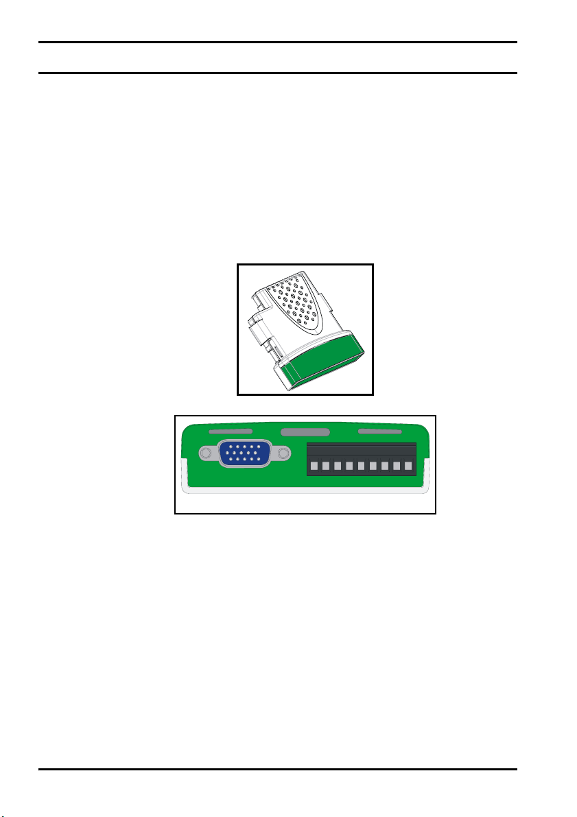
Figure 3-1 SM-Universal Encoder Plus
Figure 3-2 SM-Universal Encoder Plus connectors
234567189
SK2
PL1
3.2 Solutions Module identification
The SM-Universal Encoder Plus can be identified by:
1. The label located on the underside of the Solutions Module.
2. The colour coding across the front of the Solutions Module. All Unidrive SP
Solutions Modules are colour coded, with the SM-Universal Encoder Plus being
light green.
3. The packaging label which identifies the module as either an issue 3 or issue 4
module e.g (firmware V04.xx.xx being an issue 4 module).
4. Pr x.02 e.g (04.xx) being an issue 4 module (Pr x.02 where x refers to either menu
15, 16 or 17 as detailed in section 4.1).
8 SM-Universal Encoder Plus User Guide
www.controltechniques.com Issue Number: 6
Page 9
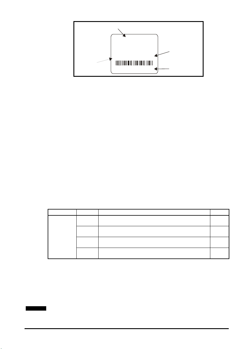
Figure 3-3 SM-Universal Encoder Plus label
e
Solutions Module
name
SM-Universal
Encoder Plus
Firmware
04.xx.xx
Firmware
Ser No : 3000005001
3.2.1 Date code format
The date code is split into two sections: a letter followed by a number.
The letter indicates the year, and the number indicates the week number (within the
year) in which the Solutions Module was built.
The letters go in alphabetical order, starting with A in 1990 (B in 1991, C in 1992 etc.).
Example:
A date code of L35 would correspond to week 35 of year 2002.
3.3 Set-up parameters
All parameters associated to the SM-Universal Encoder Plus can be found in either
menu 15, 16, or 17. Each of menus 15, 16, and 17 refer to one of the available slots into
which the SM-Universal Encoder Plus can be fitted. See Figure 5-1 on page 24.
3.4 Compatible with encoder types
The SM-Universal Encoder Plus will allow for the following encoders to be used with
Unidrive SP:
3.4.1 Incremental encoders Ab, Fd, Fr and SC
These types of encoders give incremental position and can only be used for control in
Closed Loop Vector mode, or alternatively could be used for operation in servo mode. If
used in servo mode a phasing test is required at every power-up.
Type Encoder Description Pr x.15
Quadrature incremental encoder.
Ab
With or without marker pulse.
Incremental encoder with frequency and direction outputs.
Fd
Incremental
With or without marker pulse.
Incremental encoder with forward and reverse outputs.
Fr
With or without marker pulse.
SinCos encoder with no serial communications
SC
No optional marker pulse.
StdJ41
Customer
and date cod
Serial number
0
1
2
6
Quadrature detection logic determines rotation from the phase relationship of the two
channels.
These encoders are available with a marker pulse, which identifies each individual
rotation of the disc, and is also used to reset the drive position parameter. The
incremental encoder can be used when operating in Closed Loop Vector mode, with the
optional marker pulse not being required for correct operation.
NOTE
With this type of feedback the Unidrive SP must carry out a phasing test to find the phase
offset angle on power up for operation in servo mode.
SM-Universal Encoder Plus User Guide 9
Issue Number: 6 www.controltechniques.com
Page 10
NOTE
NOTE
SC
In this case the incremental positional information and rotation is determined from the
phase relationship of the analogue sine/cosine feedback signals. The incremental
SinCos encoder can be used when operating in the Closed Loop Vector mode.
Refer to for section 3.4.6 Comms only, (absolute encoders) SSI and EndAt on page 15
for further information on the SinCos encoder feedback signals.
Limitations
Type Encoder Max Input Frequency Max no. of Lines (LPR)
Ab
Incremental
Fd 600kHz*
Fr
SC
115kHz* (full resolution)
250kHz (reduced resolution)
50,000
* Max input frequency = LPR x max rpm / 60
The maximum speed in rpm which an encoder connected to the SM-Encoder Plus can
reach can be calculated from:
Max rpm = (60 x Max input frequency) / Encoder LPR
e.g. For a 4096 line encoder the maximum rpm would be:
(60 x 600 x 10
3
) / 4096 = 8789rpm
NOTE
The absolute maximum input frequency for any SC, SinCos encoder used with the SMUniversal Encoder Plus is 250 kHz.
NOTE
With this type of feedback the Unidrive SP must carry out a phasing test to find the phase
offset angle on power up for operation in servo mode.
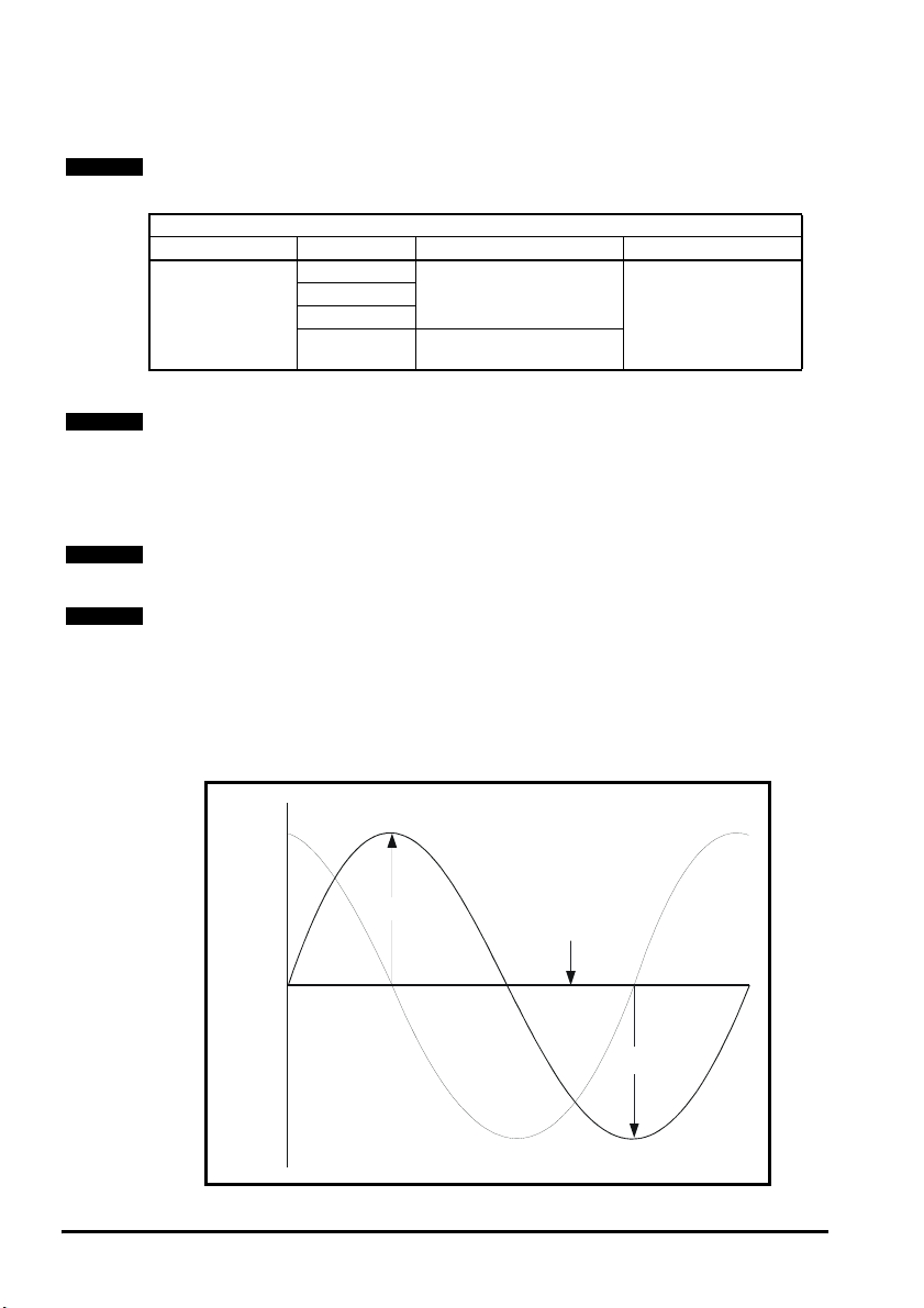
3.4.2 SinCos encoder feedback signals
For the SinCos encoder to be compatible with the SM-Universal Encoder Plus, the
output signals from the encoder must be a 1V peak to peak differential voltage (across
sinref to sin and cosref to cos).
Figure 3-4 Stegmann SinCos encoder feedback signals
0.5 Vdc
2.5Vdc
SIN
COS
REFSIN,
REFCOS
.
0.5 Vdc
10 SM-Universal Encoder Plus User Guide
www.controltechniques.com Issue Number: 6
Page 11
Stegmann
s
Stegmann encoders typically have a 2.5Vdc offset. The sinref and cosref are a flat DC
level at 2.5Vdc and the cos and sin signals have a 1V peak to peak waveform biased at
2.5Vdc.
The result is a 1V peak to peak differential voltage as show in Figure 3-4.
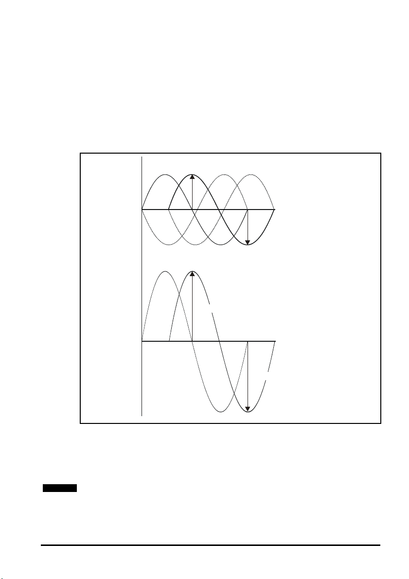
Heidenhain
The Heidenhain Sin and Cos signals with respect to zero volts are offset at 2.5Vdc as
shown in Figure 3-5.
The feedback signals which are seen by the SM-Universal Encoder Plus are the
differential signals Sin - Sin\ and Cos - Cos\ as in Figure 3-5, these being 90° phase
shifted and at 1Vdc peak to peak.
Figure 3-5 Heidenhain SinCos encoder feedback signals
0.25Vdc
NOTE
2.5Vdc
COS
SIN
SIN, COS signals
with respect to 0V
(offset at 2.5Vdc)
COS ref SIN ref
0.25Vdc
0.5Vdc
Differential signal
received by
SM-Universal
Encoder Plus
0Vdc
SIN
COS
0.5Vdc
Encoders are available which have a 1V peak to peak voltage on sinref, sin, cos and
cosref. This results in a 2V peak to peak voltage seen at the Solutions Module terminals.
The drive will still function with this type of encoder, however reduced performance in
the form of speed and torque ripple at four times the line rate will result.
(line rate = no. of lines per revolution x revolutions per second.)
It is recommended that encoders of this type are not used with Unidrive SP, and that the
encoder feedback signals should meet the above parameters (1V peak to peak).
SM-Universal Encoder Plus User Guide 11
Issue Number: 6 www.controltechniques.com
Page 12

3.4.3 SinCos Signal Values
When operating with a SinCos encoder, which has no comms or commutation signal
inputs (Pr x.15 = 6), the internal differential SinCos signal values are written to both
Pr x.42 (Sin) and Pr x.43 (Cos) as an unsigned numbers.
For further details refer to both Pr x.42 and Pr x.43
3.4.4 Incremental plus commutation, (absolute encoders) Ab.SErvo, Fd.SErvo, Fr.SErvo and SC.SErvo.
Type Encoder Description Pr x.15
Quadrature incremental encoder with commutation
outputs.
With or without marker pulse.
Incremental encoder with frequency, direction and
commutation outputs.
With or without marker pulse.
Incremental encoder with forward, reverse and
commutation outputs
With or without marker pulse.
Absolute SinCos encoder plus commutation signals
without marker pulse.
3
4
5
12
NOTE
Ab.SErvo
Incremental
plus
commutation
(absolute
encoders)
Fd.SErvo
Fr.SErvo
SC.SErvo
The incremental encoder with commutation works in the same way as the incremental
encoder except that multiple channels are used to give a discrete code for every
position increment.
When operating the drive in closed loop servo absolute position of the machine shaft is
required as soon as the drive is enabled. Because the marker signal is not effective until
the shaft passes a particular position, this cannot be used to determine the absolute
position. Therefore an encoder with additional commutation is required.
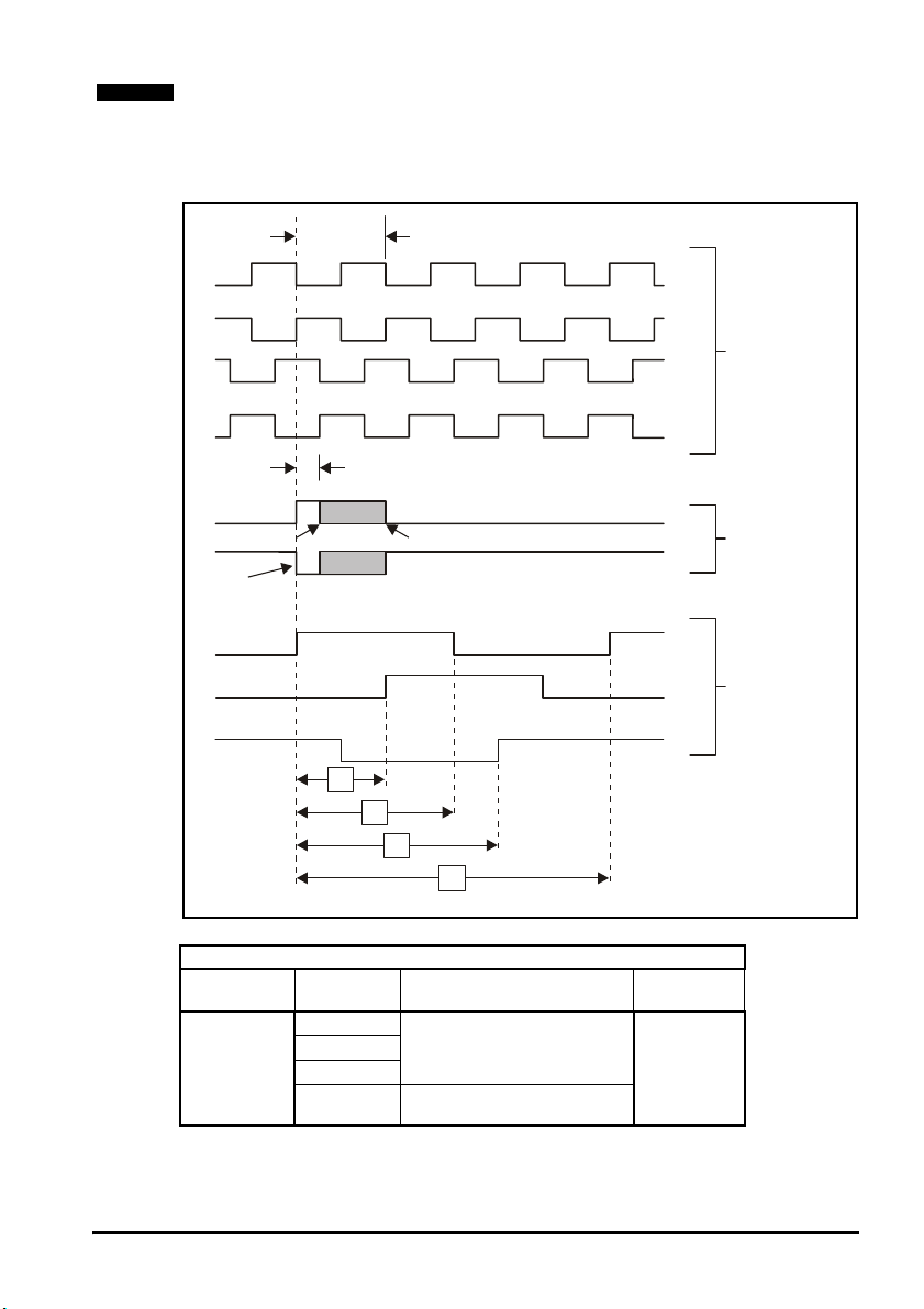
The U, V and W commutation signals should have a period that is one electrical
revolution as shown in Figure 3-6.
Therefore with a 6 pole machine the U, V and W commutation signals will repeat three
times per mechanical revolution, or with an 8 pole machine four times per mechanical
revolution etc.
The U, V and W commutation signals are used when the drive is enabled to locate the
position of the machine shaft within 60° electrical so that the current vector can be
applied within 30° electrical either side of the correct position for maximum torque
production. At certain positions of the shaft, the torque capability of the drive during this
period is reduced to 0.866 of the nominal level during initialisation.
Once the shaft has moved through a maximum of 60° electrical, one of the U, V or W
signals will change state. The location of the waveform edge is used to locate the
machine position exactly. This information is then stored by the option module and used
until power-down to place the current vector in the correct position for maximum torque.
To ensure that this process is carried out correctly the control algorithm waits for two
changes of the state of the U,V and W waveforms, at this point there will be no
additional torque ripple and maximum torque is available for all shaft positions.
Using this type of encoder does not result in any jump in position when the drive is first
enabled after power-up, but only the small reduction in specification described above for
the first 60 to 120° electrical of movement.
12 SM-Universal Encoder Plus User Guide
www.controltechniques.com Issue Number: 6
Page 13
NOTE
In Ab.SErvo, Fd.SErvo or Fr.SErvo mode only, the value in Pr x. 42 provides information
on the commutation signal inputs (UVW). Pr x.42 permits the user to determine the
current segment and status of the commutation signal inputs.
For further details refer to Pr x.42
Figure 3-6 Example of encoder feedback signals
360 electrical degrees (encoder)
°
A
Incremental
/A
signals
B
/B
90 separation of A and B
°
Z
min
max
Marker
signals
/Z
Index
alignment
reference
U
Commutation
signals
V
W
1
/
3
1
/
2
2
/
3
1
Mechanical revolution
Limitations
Type Encoder Max Input Frequency Max no. of
Ab.SErvo
Incremental
plus
commutation
Fd.SErvo
Fr.SErvo
SC.SErvo
250kHz (reduced resolution)
600kHz*
115kHz* (full resolution)
Lines (LPR)
50,000
* Max input frequency = LPR x max rpm / 60
SM-Universal Encoder Plus User Guide 13
Issue Number: 6 www.controltechniques.com
Page 14

NOTE
The maximum speed in rpm which an encoder connected to the SM-Universal Encoder
Plus can reach can be calculated from:
Max rpm = (60 x Max input frequency) / Encoder LPR
e.g. For a 4096 line encoder the maximum rpm would be:
(60 x 600 x 10
3
) / 4096 = 8789rpm
3.4.5 Incremental plus comms (absolute encoders) SC.HiPEr, SC.EndAt and SC.SSI
Type Encoder Description Pr x.15
Absolute SinCos encoder using Stegmann RS485
comms protocol (HiperFace).
The option module checks the position from the sine
and cosine waveforms against the internal encoder
position using serial communications.
If an error occurs the drive trips.
Absolute SinCos encoder using EndAt comms
protocol
The option module checks the position from the sine
and cosine waveforms against the internal encoder
position using serial communications.
If an error occurs the drive trips.
Absolute SinCos encoder using SSI comms protocol
The option module checks the position from the sine
and cosine waveforms against the internal encoder
position using serial communications.
Incremental
plus
comms
(absolute
encoders)
SC.HiPEr
SC.EndAt
SC.SSI
7
9
11
NOTE
It should be noted that the SC.HiPEr, SC.EndAt and SC.SSI encoders must be initialised
before their position data can be used. The encoder is automatically initialised at powerup, after all trips are reset, or when the initialisation parameter (Pr 3.47) is set to 1. If the
encoder is not initialised or the initialisation is invalid, the Solutions Module initiates a trip
7, and the drive will trip on SLX.Er.
NOTE
A flux alignment test is required during set up to determine the phase offset angle for
operation in servo mode.
The SC.HiPEr and SC.EndAt encoders can be considered as a mixture of an
incremental encoder (analogue SinCos feedback signals) and an absolute encoder
(serial link used for absolute position). The only difference between the encoders being
the serial link protocol.
The RS 485 serial link allows the drive at power up to interrogate the SinCos encoder in
comms channel order to determine the initial absolute position of the encoder shaft.
When the interrogation is complete and the initial absolute position is known the position
is incremented from the absolute value using the analogue sine/cosine interface.
The comms channels can then be used for either error checking, Pr x.17 or data
transfer, Pr x.42 to Pr x.43. The incremental SinCos encoder can be used when
operating in either Closed Loop Vector or Closed Loop Servo modes.
14 SM-Universal Encoder Plus User Guide
www.controltechniques.com Issue Number: 6
Page 15

Limitations
Type Encoder Max Input Frequency * Max no. of
Incremental plus
commutation
SC.HiPEr
SC.EndAt
SC.SSI
115khz (full resolution)
250kHz (reduced resolution)
* Max input frequency = LPR x max rpm / 60
Lines (LPR)
50,000 9600k
Max Baud
Rate (bits/s)
2M
NOTE
The maximum speed in rpm which an encoder connected to the SM-Encoder Plus can
reach can be calculated from:
Max rpm = (60 x Max input frequency) / Encoder LPR
e.g. For a 4096 line encoder the maximum rpm would be:
3
) / 4096 = 8789rpm
NOTE
(60 x 600 x 10
The absolute maximum input frequency for any SC, SinCos encoder used with the SMUniversal Encoder Plus is 250 kHz.
3.4.6 Comms only, (absolute encoders) SSI and EndAt
Type Encoder Description Pr x.15
Absolute EndAt only encoder
Additional communications with the encoder is not
possible.
Absolute SSI only encoder.
SSI
Additional communications with the encoder is not
possible.
NOTE
Comms
EndAt
(absolute)
It should be noted that EndAt and SSI encoders must be initialised before their position
data can be used. The encoder is automatically initialised at power-up, after trips 1 - 8
are reset, or when the initialisation parameter (Pr 3.47) is set to 1. If the encoder is not
initialised or the initialisation is invalid the Solutions Module initiates a trip 7, and the drive
will trip on SLX.Err.
SSI, EndAt
Encoders with either an EndAt (transfer standard from Heidenhain) or SSI
(Synchronous Serial) interface can transmit data synchronised with a CLOCK signal
provided from the drive. This makes it possible to transmit position values quickly and
reliably with only four signal lines.
The main difference between the SSI and the EndAt being that the standard SSI
encoder is Uni-directional whereas the EndAt is Bi-directional. The data transfer for both
the SSI and the EndAt takes the form of EIA Standard RS 485.
The SSI (Synchronous Serial interface) and EndAt (Encoder Data) encoders have a
serial link between the encoder and drive which passes all positional information.
The encoder operates in the following manner:
1. A clock signal at a user defined frequency is sent out to the encoder.
2. Once a downward latching signal is detected by the encoder.
3. Followed by the data request.
4. The encoder then returns data to the drive at the clock frequency.
8
10
SM-Universal Encoder Plus User Guide 15
Issue Number: 6 www.controltechniques.com
Page 16
Limitations
Type Encoder Max Baud
Comms Only
EndAt 2Mbits/sec
SSI 2Mbits/sec
Rate (bits/sec)
Max Speed
rpm
40,000rpm
NOTE
The SSI input at default is configured to operate in Gray code through Pr x.18, this can
be configured to operate in binary format by setting Pr x.18 = 1. The simulated SSI
encoder output will operate with both binary format and Gray code, the mode being
configured through Pr x.28.
NOTE
A flux alignment test is required during set up to determine the phase offset angle for
operation in servo mode.
3.4.7 Linear Encoders
Type Encoder Description Pr x.15
Ab.SErvo Digital hall effect + Linear quadrature incremental encoder 3
SC.SErvo Digital hall effect + Linear SinCos incremental encoder 12
SC.HiPEr
SC.EndAt 9
SC.SSI 11
EndAt
NOTE
Linear
encoder
Linear Quadrature / SinCos Encoder
These types of encoder are purely incremental and have no information for
commutation. With this type of feedback the Unidrive SP must carry out a phasing test
to find the phase offset angle on every power up for operation in servo mode.
Digital Hall Effect + Linear Quadrature / SinCos Incremental encoder
These types of encoder have digital hall effect signals U, V, W plus complements that
supply the necessary signals for deriving the position at power-up. The quadrature
signals, incremental or SinCos are used for speed feedback. A flux alignment test is
required during set-up to determine the phase offset angle for operation in servo mode.
Linear Absolute SinCos encoder
These types of encoder derive the absolute position at power-up via the comms
protocol, Hiperface, EndAt or SSI with the incremental signals, SinCos, being used for
incremental position and speed feedback.
A flux alignment test is required during set-up to determine the phase offset angle for
operation in servo mode.
Linear Absolute encoder
These types of feedback are comms only encoders, which derive the position at powerup via either the EndAt or SSI comms protocols. The position feedback is also passed
via comms during operation. The comms only encoders operate with the drive being the
master and passing the required clock signal. A flux alignment test is required during
set-up to determine the phase offset angle for operation in servo mode.
Refer to section 3.4.2 SinCos encoder feedback signals on page 10 for further
information on the SinCos encoder feedback signals.
Ab Linear quadrature encoder 0
SC Linear SinCos encoder 6
Linear absolute SinCos encoder
Linear absolute encoder
SSI 10
7
8
16 SM-Universal Encoder Plus User Guide
www.controltechniques.com Issue Number: 6
Page 17

NOTE
Type Encoder Max input frequency Max no. of
Ab
Ab.SErvo
SC
Linear
encoder
SC.SErvo
SC.HiPEr 9600k
SC.EndAt
SC.SSI
EndAt
250kHz (reduced resolution)
SSI
Limitations
600kHz
115kHz (full resolution)
lines
50,000
Max baud
rate
2Mbits/sec
In some applications using Closed Loop Vector control, the maximum speed of the
system is above the speed at which the encoder feedback frequency is too high to be
used by the drive. For these types of applications Pr 3.24 Closed Loop Vector Mode
should be set to 2 (Closed Loop Vector Mode with no maximum speed limit) for low
speed operation and 3 (Closed Loop Vector Mode without position feedback and with
no maximum speed limit) for high-speed operation. It should be noted that the drive no
longer checks that the maximum encoder frequency cannot be exceeded, and so the
user must ensure that Pr 3.24 is set to 3 before the encoder frequency limit is reached.
SM-Universal Encoder Plus User Guide 17
Issue Number: 6 www.controltechniques.com
Page 18

4 Encoder feedback selection
4.1 Encoder selection
The SM-Universal Encoder Plus option module supports a total of 12 encoder types.
These range from Quadrature relative encoders to Quadrature plus Commutation,
SinCos plus Comms and Comms only absolute encoders.
When selecting an encoder there are essentially two groups these being absolute and
relative. Absolute encoders providing the absolute position at power-up to the drive and
only requiring a phasing test during the initial set-up when used for closed loop servo
operation. Relative encoders requiring a phasing test at every power up when used for
closed loop servo operation.
Either absolute or relative encoders can be used for closed loop vector operation.
4.1.1 Absolute encoders
The absolute encoders which are compatible with Unidrive SP are as follows:
• Ab.SErvo, Fd.SErvo, Fr.SErvo, SC.SErvo
• SC.HiPEr, SC.EndAt, SC.SSI
• EndAt, SSI
4.1.2 Non absolute encoders
At power up the encoder counters will start to increment from the incremental position
as the encoder rotates, the position is reset to zero on detection of the first marker.
Compatible relative encoders being:
• Ab, Fd, Fr
•SC
4.1.3 Standard feedback
Basic encoder (Ab, Fd, Fr)
• 6 wire (+ 2 for marker if required)
• Up to 50,000ppr
• Ab - quadrature signals (best noise immunity)
• Fd - frequency and direction
• Fr - forward and reverse
• Marker input (only connect if needed, low noise immunity)
• Freeze based directly on the encoder counter
• Termination control
• Wirebreak detection
NOTE
A quadrature encoder will provide sufficient performance for most applications once tuned.
Servo encoders (Ab.SErvo, Fd.SErvo, Fr.SErvo, SC.SErvo)
• 12 wire (+ 2 for marker if required not SC.SErvo)
• Commutation signals used for motor control until two valid changes
• Ab, Fd, Fr and SC signals used for motor control after initial movement, and
continuously for speed feedback.
• PPR non power of 2 from S/W version 1.06.01
• Marker input (not SC.SErvo)
• Freeze based directly on the encoder counter
• Termination control (not for commutation signals)
• Wirebreak detection
• Phase error detection based on commutation signals
18 SM-Universal Encoder Plus User Guide
www.controltechniques.com Issue Number: 6
Page 19

Non-absolute SINCOS encoder (SC)
•6 wire
• Nominally the feedback resolution is sine waves per revolution plus 9 additional bits
of interpolation information
• High resolution speed feedback, generally for induction motors but also servo
motors with use of minimal movement phasing test
• No marker input
• Freeze is based on the time of the freeze event and interpolation between samples
• Wirebreak detection
• Initialisation required to align the analogue signals with the encoder counter
4.1.4 High resolution feedback
Stegmann Hiperface SINCOS encoders (SC.HiPEr)
•8 wire
• 8 - 12V supply
• Absolute position determined via asynchronous comms
• Nominally the feedback resolution is sine waves per revolution plus 9 additional bits
of interpolation information
• No marker input
• Freeze is based on the time of the freeze event and interpolation between samples
• Wirebreak detection
• Auto-configuration is possible
• Encoder phase error detection using comms
• Comms includes message XOR checksum
• Initialisation required to obtain the absolute position via comms and to align the
analogue signals with the encoder counter
NOTE
An SC.HiPEr encoder will provide high performance and is recommended for precision
applications.
Heidenhain EndAt SINCOS encoders (SC.EndAt)
• 10 wire
• 5V supply
• Absolute position determined via synchronous comms
• Nominally the feedback resolution is sine waves per revolution plus 9 additional bits
of interpolation information
• No marker input
• Freeze is based on the time of the freeze event and interpolation between samples
• Wirebreak detection
• Encoder phase error detection using comms
• Comms includes CRC check
• Auto-configuration is possible
• Initialisation required to obtain the absolute position via comms and to align the
analogue signals with the encoder counter
• Compatible with EndAt 2.1
NOTE
An SC.EndAt encoder will provide high performance and is recommended for precision
applications.
SM-Universal Encoder Plus User Guide 19
Issue Number: 6 www.controltechniques.com
Page 20

NOTE
SSI SINCOS encoders (SC.SSI)
• 10 wire
• Absolute position determined via synchronous comms
• Nominally the feedback resolution is sine waves per revolution plus 9 additional bits
of interpolation information
• No marker input
• Freeze is based on the time of the freeze event and interpolation between samples
• Wirebreak detection
• Auto-configuration is not possible
• Encoder phase error detection using comms
• The comms protocol does not include any error checking
• Initialisation required to take the absolute position via comms and to align the
analogue signals with the encoder counter
• Gray code or binary format encoders
• Power supply fail bit monitoring
SSI only encoder (SSI)
•8 wire
• Position obtained via synchronous comms
• Not auto configurable, no error checking, too slow for use as motor feedback
• Feedback resolution defined by comms resolution
• No marker input
• Freeze is based on the time of the freeze event and interpolation between samples
• Wirebreak detection by comms error
• Gray code or binary format encoders
• Power supply fail bit monitoring
SSI only encoders are not recommended for use as motor feedback, but can be used
for either positioning or reference.
EndAt only encoders (EndAt)
•8 wire
• 5V supply
• Position obtained via synchronous comms
• Feedback resolution defined by comms resolution
• No marker input
• Freeze is based on the time of the freeze event and interpolation between samples
• Wirebreak detection by comms error
• Comms includes CRC check
• Auto-configuration is possible
• Compatible with EndAt 2.1 (present version)
• Will allow access to interpolated position, but not extended functions with EndAt 2.2
NOTE
An EndAt encoder will provide high performance and is recommended for precision
applications.
4.2 Considerations
When selecting an encoder there are a number of considerations, as follows, with these
being application, drive operation, and encoder specification dependant.
4.2.1 Application dependant
1. Operating mode
2. Is the application a positioning application where high resolution is required
20 SM-Universal Encoder Plus User Guide
www.controltechniques.com Issue Number: 6
Page 21

3. Is absolute position required at every power up, for example for operation in servo
mode where a phasing test is not possible at every power-up
4. What resolution is required (e.g. AB 1024 encoder = 10bit resolution, SC.HiPEr
1024 = 19 bit resolution)
5. What environment is the encoder to be installed in
6. What cable lengths are to be used (encoders with comms do have restricted cable
lengths due to comms baud rate)
7. Encoder supply voltage should be selected dependant upon the cable lengths due
to voltage drop
8. Are motor objects to be saved to the encoder
4.2.2 Drive operation dependant
1. When operating in closed loop servo mode the drive requires the absolute position
at power-up, be this from an absolute encoder or through a phasing test at every
power-up
2. When operating in closed loop vector either an absolute or non-absolute encoder
can be used
3. Encoder power supply and loading when operating with long cable lengths
4.2.3 Encoder specification dependant
1. Encoder voltage levels, are these compatible with the drive
2. Incremental encoder signals are these compatible (SC, Ab, Fr, Fd)
3. Incremental signals do not exceed maximum input frequency for option module
4. Comms encoder protocol is compatible (HiPEr, EndAt, SSI)
5. Comms encoder baud rate is compatible with drive
6. Application cable lengths do not exceed incremental signals cable length
7. Application cable lengths do not exceed the recommended cable length for comms
operation, this being baud rate specific.
8. Encoder loading does not exceed encoder power supply from module (external
power supply should be used if this is the case).
SM-Universal Encoder Plus User Guide 21
Issue Number: 6 www.controltechniques.com
Page 22

4.2.4 Encoder data
The following table compares compatible encoders for Unidrive SP
Type
AB, Fd, Fr
AB.SErvo
Fd.SErvo
Fr.SErvo
SinCos Incremental
SC.SErvo
SC.HiPEr
SC.EndAt
SC.SSI
EndAt Comms 15 Full
Incremental +
Marker
Incremental +
Commutation +
Marker
Incremental +
Commutation
Incremental +
Comms
Incremental +
Comms
Incremental +
Comms
SSI Comms 15 Full
Positional
Resolution
15bit None
15bit Cntrl.only
15bit + 9bit =
24bit
15 bits Full
15bit + 9bit =
24bit
15bit + 9bit =
24bit
15bit + 9bit =
24bit
Absolute
Mode
None
Full
Full
Full
Turns Cost Wires
Lowest 6 Fast
Low 12/14 Fast
Single
Medium 6 Fast
or Multi
Single
Medium 12 Fast
or Multi
Single
or Multi
Single
or Multi
Single
or Multi
Single
or Multi
Single
or Multi
High 8 Fast
High 10 Fast
High 10 Fast
High 6 Fast
Medium 6 Slow
4.3 Drive resolution / Feedback accuracy
The following values calculated are not a direct representation of performance at the
motor shaft, with the motors inductance and load inertia smoothing out the shaft value to
a much lower level. The value calculated is the instantaneous change in the internal
speed feedback value seen by the drive between sample periods, and when the
number of counts per revolution changes by 1 count.
This change is due to at any given speed it is unlikely that the number of counts per
sample period will always be a whole number i.e. 1 in 10 sample periods may have an
extra pulse to ensure the average speed is as demanded.
4.3.1 Available resolution
NOTE
The following Quadrature and SinCos type incremental encoders are available with
various lines per revolution with the Unidrive SP being compatible with encoders
ranging from 1 PPR (4 CPR) to 50,000 PPR (200,000CPR).
The comms only encoders which include both EndAt and SSI are also available with
various comms resolutions with Unidrive SP being compatible up to 32bits.
Ab Quadrature Incremental Encoder
• A 4096 LPR encoder has 4096 pulses per channel, and 16,384 edges. Available
resolution = 16,384 counts / turn.
SC Incremental Encoder
• An SCS50 SinCos encoder has 1024 sine waves per revolution with the drive
interpolating each sine wave to 9bits worth of resolution giving a total resolution of 2
x 1024 x 512 = 1,048,576 counts per revolution
Update
rate
IP
Rating
50
64
50
64
40 7 – 12
40 7 – 12
40 7 – 12
67 5
64
656610 – 32
67 5
64
656610 – 32
Supply
voltage
5 – 30
5 – 30
22 SM-Universal Encoder Plus User Guide
www.controltechniques.com Issue Number: 6
Page 23

EndAt Comms Only Encoder
• An EndAt comms only encoder has 13 bits giving a total resolution of = 8192 counts
per revolution
Comparing a 4096 PPR incremental encoder to a SCS50 SinCos encoder the SCS50
SinCos encoder will have a factor of 128 less ripple than the 4096 PPR encoder.
Therefore the encoder selected can influence the digital torque ripple significantly and
should be considered on high resolution / accuracy applications. The following table
shows both the digital torque ripple and available resolution for various encoder types.
NOTE
Feedback Device Digital Torque Ripple Available Resolution
Quadrature
Incremental
Comms
SinCos
Incremental
The above figures are independent of the operating speed. If the figures are
1024 59rpm 4096
4096 14rpm 16384
EndAt 29.43rpm 13bit
EndAt 1.83rpm 17bit
512 0.23rpm 2048 * 512
1024 0.11rpm 4096 * 512
recalculated for a 750 rpm then the number of counts is halved but the speed change
for 1 count is the same.
4.3.2 Internal digital torque ripple calculation
Following is an example of the internal digital torque ripple calculation
AB Quadrature Encoder
1024 line encoder running at 1500rpm and Unidrive SP speed loop sample time =
250us
• 1500rpm / 60s = 25 rev / s
• 25 rev / s x 1024ppr = 25600 pulses / s
• 25600 pulses / s x 4edges = 102400 edges / s
• 102400 edges / s x 250 x 10 -6 = 25.6 edges per sample period
Therefore due to the digitisation of the encoder feedback the average number of edges
seen will be 25.6, but this must be due to the relevant number of 25 and 26 edges over
an infinite length of time. As such:
25 edges / 250 x 10 -6 = 100,000 edges / sec.
100,000 / 4 = 25,000 edges
25,000 / 1024 = 24.4 rev / s
24.4 x 60 = 1464.8 rpm
26 edges / 250 x 10 -6 = 104,000 edges/ sec.
104,000 / 4 = 26,000 edges
26,000 / 1024 = 25.4 rev / s
25.4 x 60 = 1523.4 rpm
1523 - 1464 = 59rpm
The difference of 1 pulse gives an instantaneous speed change of 59 rpm.
SM-Universal Encoder Plus User Guide 23
Issue Number: 6 www.controltechniques.com
Page 24
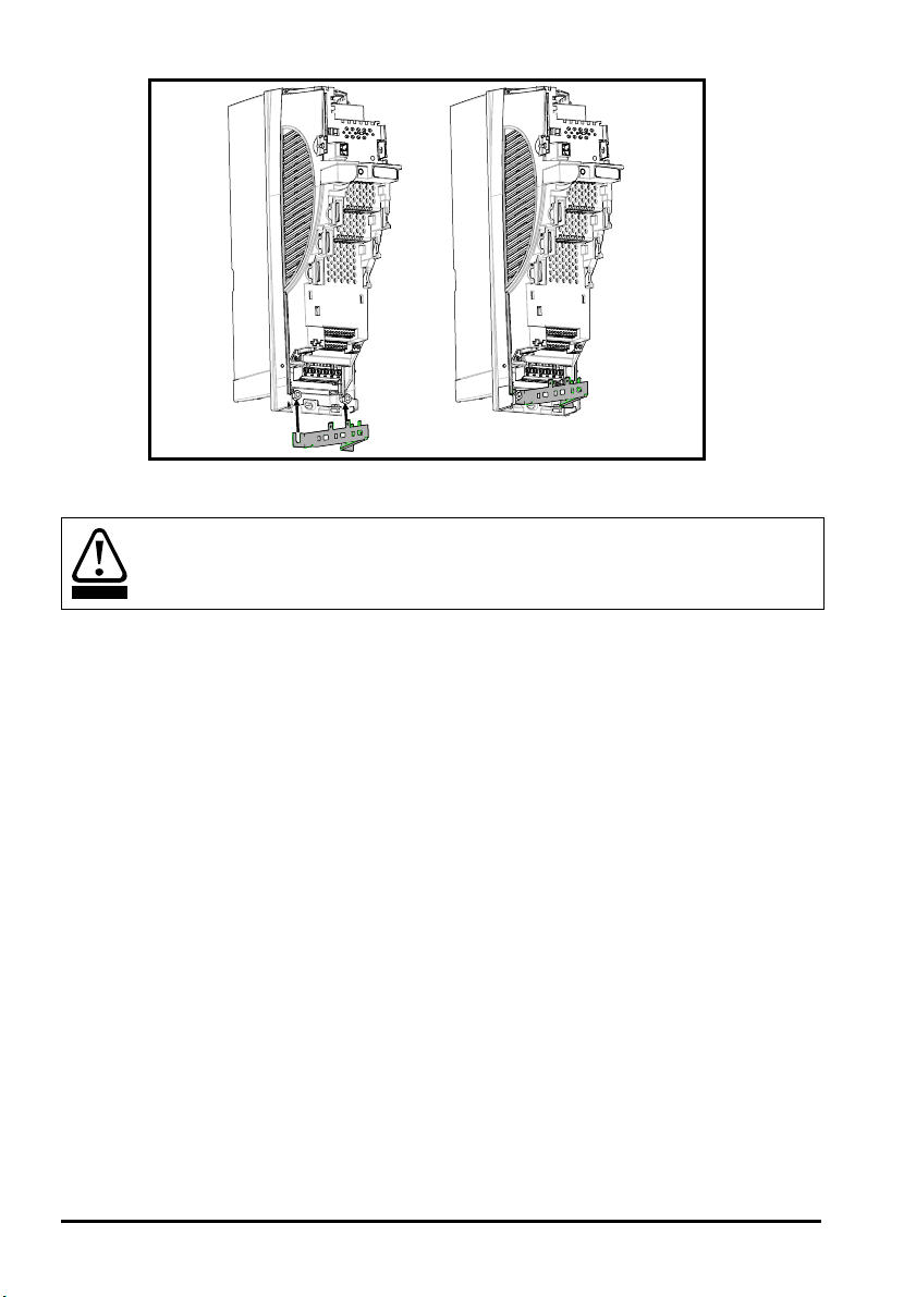
5 Installing the SM-Universal Encoder Plus
e
5.1 Solutions Module slots
Before installing the SM-Universal Encoder Plus, refer to Chapter 2 Safety
WARNING
Information on page 6.
There are three slots available, which the Solutions Module can be plugged into as
shown in Figure 5-1. The Solutions Module can be plugged into either one of these, but
it is recommended that slot 3 be used for the first Solutions Module then slot 2 and slot
1. This ensures maximum mechanical support for the Solutions Module once fitted.
Figure 5-1 Location of slots 1, 2 and 3 on the Unidrive SP
Solutions Module
slot 1 (Menu 15)
Solutions Module
slot 2 (Menu 16)
Solutions Modul
slot 3 (Menu 17)
5.2 Installation
1. Before installing the SM-Universal Encoder Plus in the Unidrive SP, ensure the AC
supply has been disconnected from the drive for at least 10 minutes.
2. Ensure that both the +24V, and +48V backup power supplies are disconnected from
the drive for at least 10 minutes.
3. Check that the exterior of the SM-Universal Encoder Plus is not damaged, and that
the multi-way connector is free from dirt and debris.
4. Do not install a damaged or dirty SM-Universal Encoder Plus in the drive.
5. Remove the termin al cover from the drive. (For removal / re-fitting instructions, see
Unidrive SP Solutions Module Installation Sheet provided with the Solutions
Module.)
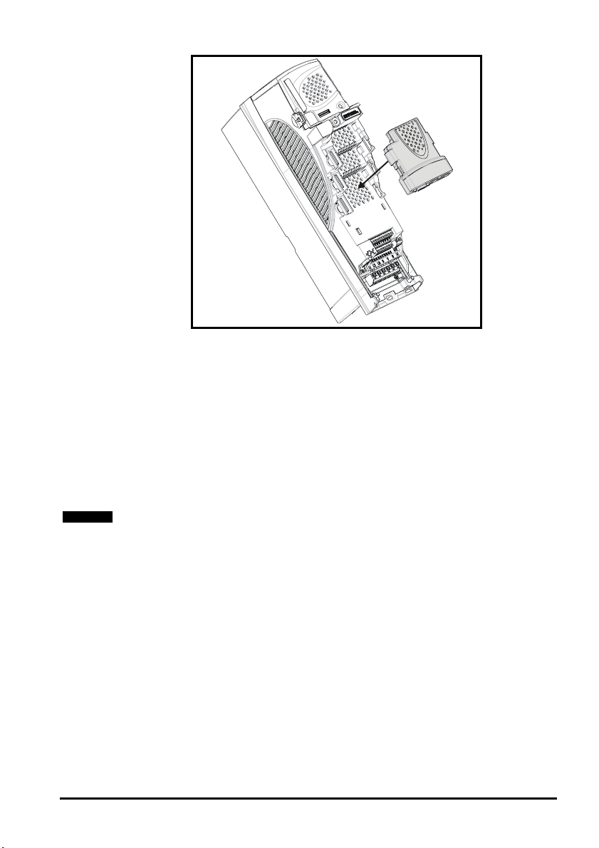
6. Position the drive connector of the SM-Universal Encoder Plus over the connector
of the appropriate slot in the drive and push downwards until it locks into place.
24 SM-Universal Encoder Plus User Guide
www.controltechniques.com Issue Number: 6
Page 25
NOTE
Figure 5-2 Fitting the SM-Universal Encoder Plus
7. Re-fit the terminal cover to the drive. (For removal / re-fitting instructions, see
Unidrive SP Solutions Module Installation Sheet provided with the Solutions
Module.)
8. Connect the AC supply to the drive.
9. Set Pr 0.49 to L2 to unlock read only security.
10. Check that Menu 15 (slot 1), 16 (slot 2), or 17 (slot 3) parameters are now available.
11. Check that Pr 15.01, Pr 16.01 or Pr 17.01 show the correct code for the SM-
Universal Encoder Plus (code = 102).
12. If the checks in steps 10 and 11 fail, either the SM-Universal Encoder Plus is not
fully inserted, or the Solutions Module is fault.
13. If a trip code is now present refer to Chapter 10 Diagnostics on page 98.
Check the SM-Universal Encoder Plus is the correct issue and has the correct software.
• Issue 3 - V.03.xx.xx
• Issue 4 - V.04.xx.xx
Encoder connections
In order to ensure correct operation there are a number of checks which should be
carried out:
• Ensure the encoder is securely mounted to the motor as spurious operation can
result due to the encoder slipping whilst the motor is rotating.
• Ensure encoder connections to both the encoder and the Solutions Module
terminals are secured, intermittent connections can result in spurious operation or
the Solutions Module not detecting the feedback signals.
• Ensure screen and grounding recommendations as specified in Chapter
5.5 Encoder shield connections on page 28, Encoder, Shield connections of this
User guide are followed to prevent noise being induced on the encoder feedback
signals. Noise induced on encoder feedback cables cannot only result in spurious
operation but in extreme cases can result in encoder failure and/or damage to the
Solutions Modules encoder input.
SM-Universal Encoder Plus User Guide 25
Issue Number: 6 www.controltechniques.com
Page 26
• Encoder feedback and communications data is transmitted from an encoder as low
S
voltage analogue or digital signals. Ensure that electrical noise from the drive or
motor does not adversely affect the encoder feedback. Also refer to drive and motor
instructions given in Chapter 4 Electrical Installation in the Unidrive SP User Guide,
and that the encoder feedback wiring and shielding recommendations are followed
in section 5.5 Encoder shield connections on page 28.
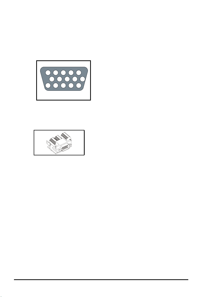
5.3 Terminal descriptions
Figure 5-3 Connector SK2 terminal descriptions
K2
12345
678910
1112131415
15 way female D-type
The standard connector SK2 provided on the SM-Universal Encoder Plus is a 15 way DType requiring a similar 15 way D-Type for connection of an encoder. A standard 15 way
D-Type has solder connections, the following UT01 allows direct connection to the 15
way D-Type on the Solutions Module providing screw terminals for encoder connection.
Figure 5-4 15-way D-type converter
Each terminal is appropriately labelled on the printed circuit board.
26 SM-Universal Encoder Plus User Guide
www.controltechniques.com Issue Number: 6
Page 27

Figure 5-5 Connector SK2 terminal descriptions
Encoder
Term
Ab Fd Fr
1AFF A F F Cos
2 A\ F\ F\ A\ F\ F\ Cosref Cosref Cosref
3BDR B D R Sin Sin Sin
4 B\ D\ R\ B\ D\ R\ Sinref Sinref Sinref
5Z
6 Z\ Encoder input - Data\ (input/output)
Simulated encoder
7
8
9
10
11 W Encoder input - Clock (output) W
12 W\ Encoder input - Clock\ (output) W\
13 +V
14 0V common
15 th
Aout, Fout,
Data SSI (output)
Simulated encoder
Aout\, Fout\,
Data\ SSI (output)
Simulated encoder
Bout, Dout,
Clock\ SSI (input)
Simulated encoder
Bout\, Dout\,
Clock SSI (input)
Ab.
SErvo
Fd.
SErvo
U
U\
V
V\
Fr.
SErvo
SC.
SC
HiPEr
Encoder input - Data (input/output)
Simulated encoder
Aout, Fout, Data SSI (output)
Simulated encoder
Aout\, Fout\, Data\ SSI (output)
Simulated encoder
Bout, Dout, Clock\ SSI (input)
Simulated encoder
Bout\, Dout\, Clock SSI (input)
SC.
EndAt
EndAt
Cos Cos
SSI
SC.
SSI
SC.
SErvo
U
U\
V
V\
NOTE
The simulated encoder outputs present on terminals 7, 8,9,10 (A.A\, B.B\, F.F\, D.D\) can
be through either software simulation or hardware, this being determined by Pr x.28
NOTE
No simulated encoder output is available when operating with either of the following
encoders configured at the modules input, Ab.SErvo, Fd.SErvo, Fr.SErvo, SC.SErvo due
to the commutation signals using the same inputs/outputs as used by the simulated
encoder output.
SM-Universal Encoder Plus User Guide 27
Issue Number: 6 www.controltechniques.com
Page 28
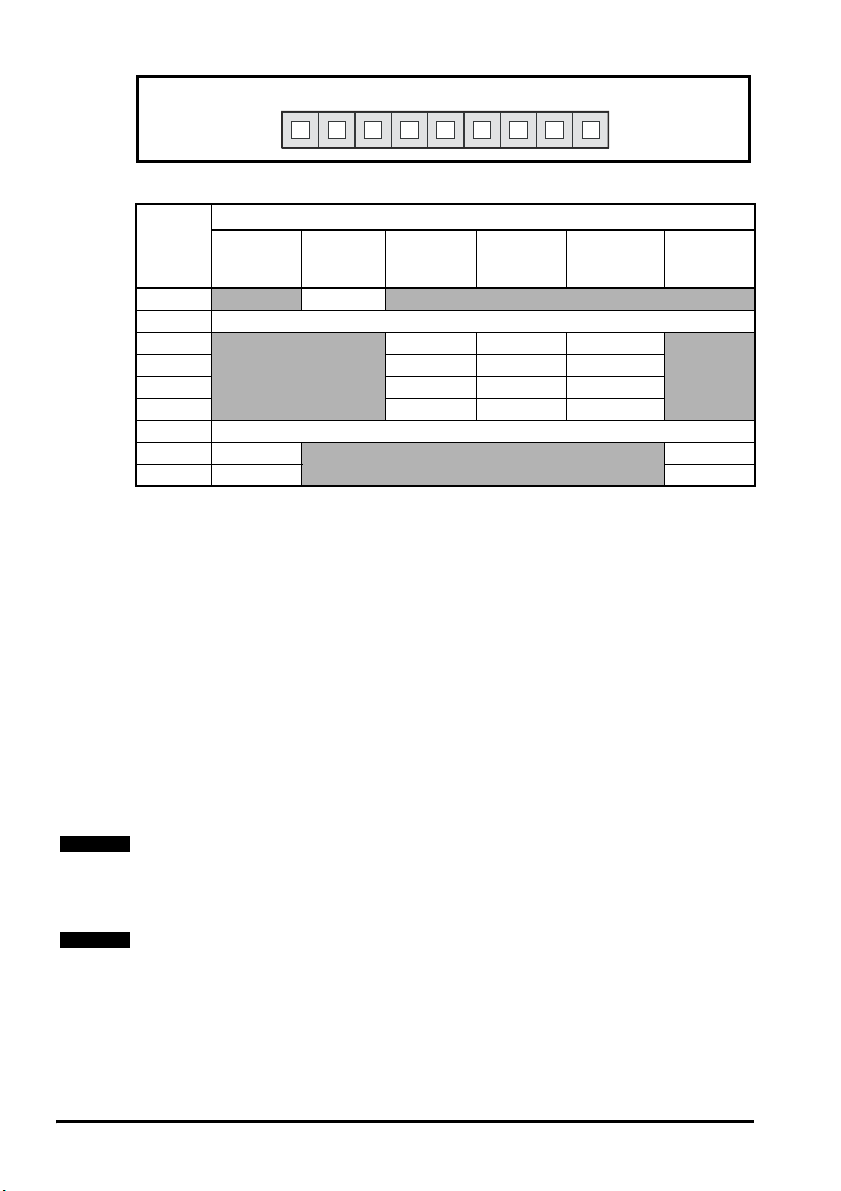
Figure 5-6 Connector PL1
Table 5.1 Connector PL1 terminal descriptions
Terminal
1
2 0V common
3
4 A\ F\ Data\
5BDClock\ (input)
6B\D\Clock (input)
7 0V common
8Freeze
9 Freeze\ Z\
Freeze
RS485
input
5.4 Power supply
The total user load of the drive and Solutions Modules if exceeded will result in a 24V
internal power supply overload, trip ‘PS.24V’.
The user load comprises of:
• the drive’s digital outputs plus the SM-I/O Plus digital outputs
or
• the drive’s main encoder supply plus the SM-Universal Encoder Plus encoder
supply
Example
If exceeding the user load:
• the drive’s main encoder supply, SM-Universal Encoder Plus encoder supply,
drive’s digital output and SM-I/O Plus digital outputs
an external 24V >50W power supply will be required. The external 24V supply should
be connected to the drives control terminals 1 and 2.
NOTE
If the encoder will exceed the SM-Universal Encoder Plus and encoder supply (5V, 8V
>300mA, 15V >200mA), the encoder must be supplied externally without a power
supply connection to the module. Ensure the 0V connection is common between both
the SM-Universal Encoder Plus and the encoder.
PL1
123456789
Freeze inputs / Encoder outputs
Freeze
+24V input
Freeze
Ab output Fd output SSI output
AFData
Marker
output
Z
NOTE
There should be no parallel connection of the external 24V supply and the encoder
supply from the drive.
5.5 Encoder shield connections
Shielding considerations are important for PWM drive installations due to the high
voltages and currents present in the output circuit with a very wide frequency spectrum,
typically from 0 to 20 MHz. Encoder inputs are liable to be disturbed if careful attention
is not given to managing the cable shields.
28 SM-Universal Encoder Plus User Guide
www.controltechniques.com Issue Number: 6
Page 29

5.6 Grounding hardware
The Unidrive SP is supplied with a grounding clamp and a grounding bracket to facilitate
EMC compliance. They provide a convenient method for direct grounding of cable
shields without the use of "pig-tails". Cable shields can be bared and clamped to the
grounding bracket using metal clips or clamps
shield must in all cases be continued through the clamp to the intended terminal on the
drive, in accordance with the connection details for the specific signal.
A suitable clamp is the Phoenix DIN rail mounted SK14 cable clamp (for cables with a
maximum outer diameter of 14mm).
See Figure 5-2 and Figure 5-3 for details on fitting the grounding clamp.
See Figure 5-4 for details on fitting the grounding bracket.
Figure 5-2 Fitting of grounding clamp (size 1 and 2)
1
(not supplied) or cable ties. Note that the
Figure 5-3 Fitting of grounding clamp (size 3)
SM-Universal Encoder Plus User Guide 29
Issue Number: 6 www.controltechniques.com
Page 30
WARNING
Figure 5-4 Fitting of grounding bracket (sizes 1 to 6)
Loosen the ground connection nuts and slide the grounding bracket in the direction
shown. Once in place, re-tighten the ground connection nuts.
On Unidrive SP size 1 and 2, the grounding bracket is secured using the power ground
terminal of the drive. Ensure that the supply ground connection is secure after fitting /
removing the grounding bracket. Failure to do so will result in the drive not being
grounded.
A faston tab is located on the grounding bracket for the purpose of connecting the drive
0V to ground should the user require to do so.
When a Unidrive SP size 4 or 5 is through-panel mounted, the grounding link bracket
must be folded upwards. A screw can be used to secure the bracket or it can be located
under the mounting bracket to ensure that a ground connection is made. This is
required to provide a grounding point for the grounding bracket as shown in Figure 5-4.
30 SM-Universal Encoder Plus User Guide
www.controltechniques.com Issue Number: 6
Page 31

Figure 5-5 Grounding link bracket in its surface mount position (as supplied
bracke
with drive)
Grounding
link bracket
Figure 5-6 Grounding link bracket folded up into its through- panel mount position
Grounding
link bracket
Mounting
t
SM-Universal Encoder Plus User Guide 31
Issue Number: 6 www.controltechniques.com
Page 32

If the control wiring is to leave the enclosure, it must be shielded and the shield(s)
clamped to the drive using the grounding bracket as shown in Figure 5-7. Remove the
outer insulating cover of the cable to ensure the shield(s) make contact with the bracket,
but keep the shield(s) intact until as close as possible to the terminals
Alternatively, wiring may be passed through a ferrite ring, part no. 3225-1004.
Figure 5-7 Grounding of signal cable shields using the grounding bracket
Encoder mounting methods
There are three methods for mounting an encoder onto a motor:
1. Galvanic isolation between encoder and motor
2. Galvanic isolation between encoder circuit and encoder body
3. No Isolation
32 SM-Universal Encoder Plus User Guide
www.controltechniques.com Issue Number: 6
Page 33

5.6.1 Encoder with galvanic isolation from motor
When galvanically isolated the encoder device is mounted to the motor with isolation
fitted between the motor housing / shaft and encoder as shown in Figure 5-7.
Figure 5-7 Galvanic Isolation from Motor
Isolation
between motor shaft
and encoder
Motor
Housing
Motor
Shaft
+5V
+5V
+5V
0V
A
A
0V
B
B
0V
Z
Z
Encoder
Circuit
Encoder
Connection
Encoder
Body
Isolation
between motor housing
and encoder housing
Encoder
Housing
An example of this is the Unimotor where isolation from the motor is achieved by
inserting a plastic mounting plate between the motor housing and encoder housing and
a plastic insert fitted in the motor shaft for encoder mounting to the motor shaft. With this
preferred method of mounting noise current is prevented from passing from the motor
housing into the encoder housing, and hence into the encoder cable. The ground
connection of the cable shield is optional, this may be required to comply with safety
measures or to reduce radiated radio frequency emissions from either the drive or
encoder.
5.6.2 Encoder circuit with galvanic isolation from encoder body
In this case the encoder device is mounted directly on the motor housing with contact
being made between the motor housing/shaft and encoder. With this mounting method
the encoder internal circuits are exposed to electrical noise from the motor housing
through the stray capacitance, and they must be designed to withstand this situation.
However this arrangement still prevents large noise currents from flowing from the
motor body into the encoder cable. The ground connection of the cable shield is
optional, this may be required to comply with safety measures or to reduce radiated
radio frequency emissions from either the drive or encoder.
SM-Universal Encoder Plus User Guide 33
Issue Number: 6 www.controltechniques.com
Page 34

Figure 5-8 Encoder Galvanically Isolated from Encoder Body
5.6.3 No isolation
As shown in Figure 5-9 the encoder 0V connection may be permanently connected to
the housing. This has the advantage that the encoder body can form a shield for its
internal circuits. However it permits noise current from the motor body to flow into the
encoder cable shield. A good quality shielded cable correctly terminated protects the
data against this noise current, but much more care is needed in ensuring correct cable
management than for the isolated cases.
Motor
Housing
Motor
Shaft
No Isolation
between motor housing
and encoder housing
No Isolation
between motor shaft
and encoder
0V
A
A
+5V
0V
B
B
+5V
0V
Z
Z
+5V
Galvanic
Isolation
Figure 5-9 No Isolation
No Isolation
between motor shaft
and encoder
Encoder
Encoder
Housing
Circuit
Encoder
Circuit
Stray
Capacitance
Encoder
Connection
Encoder
Body
Stray
Motor
Housing
Motor
Shaft
No Isolation
between motor housing
and encoder housing
0V
+5V
0V
+5V
0V
+5V
Encoder
Housing
A
A
B
B
Z
Z
Encoder
Body
Capacitance
Encoder
Connection
Optional
0V
connection
to encoder
housing
34 SM-Universal Encoder Plus User Guide
www.controltechniques.com Issue Number: 6
Page 35

5.6.4 Cable requirements
p
All mounting methods:
• Shield connection at drive terminal to 0V
• Shield connection at encoder to 0V
• It is recommended that the shielded cable should be run in a continuous length to
the terminal, to avoid the injection of noise at intermediate pigtails and to maximise
the shielding benefit.
• The shield connections ("pigtails") to the drive and encoder should be kept as short
as possible
Mounting with no isolation:
• Shield connected to ground at both ends. The connection must be made by direct
fixing of the cable to the grounded metal parts, i.e. to the encoder body and the
drive grounding bracket, as illustrated in Figure 5-7 on page 33. "Pigtails" must be
avoided. The outer sheath of the cable should be stripped back enough to allow for
the ground clamp to be fitted. The shield connection should not be broken. The
ground clamps should be located as close as possible to the drive and encoder.
• It is essential that the shielded cable should be run in a continuous length to the
terminal, to avoid the injection of noise at intermediate "pigtails" and to maximise the
shielding benefit.
In this case under no circumstances must the cable shield connection be omitted at
either end of the cable in this case, since the noise voltage may well be sufficient to
CAUTION
WARNING
destroy the line driver and receiver chips in the encoder and the drive.
Cable shield ground connection
For all mounting methods, grounding of the feedback cable shield has added benefits. It
can protect the drive and encoder from induced fast electrical transients, and prevent
radiated radio-frequency emission. However it is essential that it be carried out in the
correct manner as explained above and shown in Figure 5-11 on page 36.
Connecting the cable shield to ground at both ends carries the risk that an electrical fault
might cause excessive power current to flow in the cable shield and overheat the cable.
There must be an adequately rated safety ground connection between the motor/
encoder and the drive.
Recommended cable
The recommended cable for feedback signals is a twisted pair, shielded with an overall
shield as shown in Figure 5-10
Figure 5-10 Feedback Cable, Twisted Pair
Cable overall shield
Twisted
pair
cable
Twisted
air shield
Cable
Using this type of cable also allows for the connection of the outer shield to ground and
the inner shields to 0V alone at both drive and encoder end, when required.
SM-Universal Encoder Plus User Guide 35
Issue Number: 6 www.controltechniques.com
Page 36

NOTE
Twi
on shield
Ensure that feedback cables are kept as far away as possible from power cables and
avoid parallel routing.
Figure 5-11 Feedback cable connections
sted
pair
shield
Shield
connection
to 0V
Shield
connection
to 0V
Twisted
pair
shield
Cable
Connection
at drive
Cable
shield
Ground clamp
Cable
shield
Connection
at motor
36 SM-Universal Encoder Plus User Guide
www.controltechniques.com Issue Number: 6
Page 37

6 Getting Started
6.1 Installation
The control circuits are isolated from the power circuits in the drive by basic insulation
only, as specified in IEC60664-1. The installer must ensure that the external control
WARNING
circuits are insulated from human contact by at least one layer of insulation rated for use
at the AC supply voltage.
If the control circuits are to be connected to other circuits classified as Safety Extra Low
Voltage (SELV) (e.g. to a personal computer) an additional isolating barrier must be
included in order to maintain the SELV classification.
Encoder connections
In order to ensure correct operation there are a number of checks which should be
carried out:
• Ensure the encoder is securely mounted to the motor as spurious operation can
result due to the encoder slipping whilst the motor is rotating.
• Ensure encoder connections to both the encoder and the Solutions Module
terminals are secured, intermittent connections can result in spurious operation or
the Solutions Module not detecting the feedback signals.
• Ensure screen and grounding recommendations as specified in Chapter
5.5 Encoder shield connections on page 28, Encoder, Shield connections of this
User guide are followed to prevent noise being induced on the encoder feedback
signals. Noise induced on encoder feedback cables cannot only result in spurious
operation but in extreme cases can result in encoder failure and/or damage to the
Solutions Modules encoder input.
Encoder feedback and communications data is transmitted from an encoder as low
voltage analogue or digital signals. Ensure that electrical noise from the drive or motor
does not adversely affect the encoder feedback. Also refer to drive and motor
instructions given in Chapter 4 Electrical Installation in the Unidrive SP User Guide, and
that the encoder feedback wiring and shielding recommendations are followed in
section 5.5 Encoder shield connections on page 28.
Encoder initialisation
Encoder initialisation will occur as follows: at drive power-up, when requested by the user
via Pr
3.47
or when trips in this module (which are option module specific) are reset.
Initialisation causes an encoder with comms to be re-initialised and auto-configuration to
be performed if selected. After initialisation Ab.SErvo, Fd.SErvo, Fr.SErvo and SC.SErvo
encoders will use the UVW commutations signals to give position feedback for the first
120
°
(electrical) of rotation when the motor is restarted.
A delay is provided during initialisation for some encoders to allow the encoder to be
ready to provide position information after it has powered up. The delay is provided
during initialisation because this occurs during drive power-up and after encoder power
supply trips are reset. The delays are as follows:
Encoder type Initialisation delay
Ab, Fd, Fr, Ab.SErvo, Fd.SErvo, Fr.SErvo, SC.SErvo 250ms
SC.HiPEr 150ms, then encoder reset, then 400ms
SC.EndAt, EndAt 1.25s
All other types 1.45s
SM-Universal Encoder Plus User Guide 37
Issue Number: 6 www.controltechniques.com
Page 38

NOTE
Encoder initialisation will only occur when trips 1 through to 74 in Pr x.50, Solutions
Module error status are reset.
Pr x.18 Auto-configuration enable\SSI binary format select
When a SC.HiPEr or SC.EndAt encoder is being used, the Solutions Module will interroga te the encoder on
power-up. If Pr x.18 is set and the encoder type is recognised based on the information provided by the
encoder, the Solutions Modul e will set the encoder turns Pr x.09, the equivalent lines per revolution Pr x.10 and
the encoder comms resolution Pr x.11 for the encoder. If the encoder is recognised these parameters will all
become read only. If the encoder is not recognised, the Solutions Module will initiate a 7 trip to prompt the user
to enter the information. The Solutions Module should be able to auto-configure with any EndAt encoder where
the number of turns and lines per revolution are a power of 2, and the following Hiperface encoders: SCS 60/70,
SCM 60/70, SRS 50/60, SRM 50/60, SHS 170, LINCODER, SCS-KIT 101, SKS36, SKM36, SEK52, SEK53.
NOTE
NOTE
When operating with an SSI encoder, Pr x.18 is used to set-up the data format: 0 = Gray
code and 1 = binary format.
When using only the simulated encoder outputs from the SM-Universal Encoder Plus,
the error detection Pr x.17 should be disabled to avoid Enc2 trips.
38 SM-Universal Encoder Plus User Guide
www.controltechniques.com Issue Number: 6
Page 39

6.1.1 Incremental encoders
The following parameter set-up should be followed when configuring an Incremental
Encoder.
Incremental Encoders, Ab, Fd, Fr, SC
Before powerup
Power-up drive
Slot
identification
Select
Solutions
Module
Set-up
encoder power
supply
Set-up
encoder type
Set-up
encoder lines
per revolution
Set-up
encoder turns
Error detection
Initialisation
Ensure:
• Feedback device is connected
• Drive secure disable is not given (terminal 31)
Ensure:
• Drive displays “inh”
• If the drive trips refer to Chapter 10 Diagnostics on page 98
Identify:
• Identify slot and associated menu, 15, 16, or 17
Enter:
• Speed feedback selector Pr 3.26
1: Slot 1, 2: Slot 2, 3: Slot 3
Enter:
• Encoder power supply Pr x.13
0: 5v, 1: 8v, 2:15v
Enter:
• Encoder Type Pr x.15
0 (Ab), 1 (Fd), 2 (Fr), 6(SC)
• Equivalent lines per revolution Pr x.10
Set according to encoder, see belo w for restrictions
• Line per revo l u ti o n divider Pr x.46
The equivalent lines per revolution Pr x.10 is divided by the value in Pr x.46. This can be used
when an encoder is used where the number of lines or sine waves per pole is not an integer e.g.
128.123 lines per rev = 128.123 in Pr x.10 and 1000 in Pr x.46 giving 128123/1000 = 128.123.
Encoder Pr x.10 Equivalent lines per revolution
Ab Number of lines per revolution
Fd, Fr Number of lines per revolution / 2
SC Number of sine waves per revolution
• Encoder turns Pr x.09
Defines the maximum number of the revolution counter (when operating with an incremental
encoder) before it rolls over at zero e.g. if Pr x.09 = 5, then Pr x.04 counts up to 31 before rolling
over at zero.
Ensure:
• The required error detection is set-up in Pr x.17
Ensure:
• Position feedback is initialised Pr x.45
• A re-initialise can be carried out enabling Pr 3.47
NOTE
When operating in servo mode with either of the above Incremental encoders a flux
alignment test (Pr 5.12) is required at every power up in order to determine the phase
offset angle. The miminal movement flux alignment test can be set-up through Pr 5.14
to carry out the required test automatically at every power up.
SM-Universal Encoder Plus User Guide 39
Issue Number: 6 www.controltechniques.com
Page 40

6.1.2 Incremental plus commutation, absolute encoders
The following parameter set-up should be followed when operating with an incremental
plus commutation absolute encoder.
Incremental plus commutation, absolute encoders, Ab.SErvo, Fd.SErvo, Fr.SErvo, SC.SErvo
Before powerup
Power-up drive
Slot
identification
Select Solutions
Module
Set-up encoder
power supply
Set-up encoder
type
Set-up encoder
lines per
revolution
Set-up encoder
turns
Error detection
Initialisation
NOTE
Ensure:
• Feedback device is connected
• Drive secure disable is not given (terminal 31)
Ensure:
• Drive displays “inh”
• If the drive trips refer toChapter 10 Diagnostics on page 98
Identify:
• Identify slot and associated menu, 15, 16, or 17
Enter:
• Speed feedback selector Pr 3.26
1: Slot 1, 2: Slot 2, 3: Slot 3
Enter:
• Encoder power supply Pr x.13
0: 5v, 1: 8v, 2:15v
Enter:
• Encoder Type Pr x.15
3 (Ab.SErvo), 4 (Fd.SErvo), 5 (Fr.SErvo), 12 (SC.SErvo)
• Equivalent lines per revolution Pr x.10
Set according to encoder, see below for restrictions
Encoder Pr x.10 Equivalent lines per revolution
Ab.SErvo Number of lines per revolution
Fd.SErvo
Fr.SErvo
SC.SErvo Number of sine waves per revolution
• Encoder turns Pr x.09
Defines the maximum number of the revolution counter (when operating with an incremental
encoder) before it rolls over at zero e.g. Pr x.09 = 5, then Pr x.04 counts up to 31 before rolling
over at zero.
Ensure:
• The required error detection is set-up in Pr x.17
Ensure:
• Position feedback is initialised Pr x.45
• A re-initialise can be carried out enabling Pr 3.47
Number of lines per revolution / 2
When using the above incremental plus commutation, absolute encoders Pr x.46 lines
per revolution divider should remain at 1 to ensure correct operation.
40 SM-Universal Encoder Plus User Guide
www.controltechniques.com Issue Number: 6
Page 41

6.1.3 Incremental absolute encoders
The following parameter set up should be followed when configuring an incremental
absolute encoder.
Incremental absolute encoders, SC.HiPEr, SC.EndAt, SC.SSI
Before power-up
Power-up drive
Slot identification
Select Solutions
Module
Set-up encoder
power supply
Set-up encoder
type
Encoder comms
Auto configuration
Set-up encoder
lines per revolution
Error detection
Initialisation
NOTE
Ensure:
• Feedback device is connected
• Drive secure disable is not given (terminal 31)
Ensure:
• Drive displays “inh”
• If the drive trips refer toChapter 10 Diagnostics on page 98
Identify:
• Identify slot and associated menu, 15, 16, or 17
Enter:
• Speed feedback selector Pr 3.26
1: Slot 1, 2: Slot 2, 3: Slot 3
Enter:
• Encoder power supply Pr x.13
0: 5v, 1: 8v, 2:15v
Enter:
• Encoder Type Pr x.15
7 (SC.HiPEr), 9 (SC.EndAt), 11 (SC.SSI)
• Encoder comms baud rate Pr x.14 (EndAt, SSI)
• Encoder comms resolution Pr x.11
Where encoder comms is used for initial setting of the absolute position the comms
resolution in bits must be set correctly. The comms resolution, Pr x.11 may be set at a higher
resolution than the SinCos lines per revolution.
• Encoder turns Pr x.09
When an encoder with comms is used Pr x.09 must contain the number of bits in t he comms
message used to give the multi-turn information. For a single turn comms encoder Pr x.09
must be set to zero.
Enter:
It is possible for the drive to set-up Pr x.09, Pr x.11 and Pr x.10 automatically see Pr x.18
• Equivalent lines per revolution Pr x.10
Ensure:
• The required error detection is set-up in Pr x.17
Ensure:
• Position feedback is initialised Pr x.45
• A re-initialise can be carried out enabling Pr 3.47
If SSI power supply bit monitor feature is enabled ensure that this has been configured
in encoder setup parameters; Pr x.09, Pr x.11.
NOTE
When using the above encoders Pr x.46 lines per revolution divider should remain at 1
to ensure correct operation.
SM-Universal Encoder Plus User Guide 41
Issue Number: 6 www.controltechniques.com
Page 42

6.1.4 Comms only, absolute encoders
The following parameter set-up should be followed when configuring a Comms only
absolute encoder.
Comms only absolute encoders, EndAt and SSI
Before power-up
Power-up drive
Slot identification
Select Solutions
Module
Set-up encoder
power supply
Set-up encoder
type
Set-up data
format
Auto
configuration
Encoder comms
Error detection
Initialisation
Ensure:
• Feedback device is connected
• Drive secure disable is not given (terminal 31)
Ensure:
• Drive displays “inh”
• If the drive trips refer to Chapter 10 Diagnostics on page 98
Identify:
• Identify slot and associated menu, 15, 16, or 17
Enter:
• Speed feedback selector Pr 3.26
1: Slot 1, 2: Slot 2, 3: Slot 3
Enter:
• Encoder power supply Pr x.13
0: 5v, 1: 8v, 2:15v
Enter:
• Encoder Type Pr x.15
8 (EndAt), 10 (SSI)
Enter:
• SSI encoder format Pr x.18 (0 Gray code, 1 Binary format)
Enter:
• EndAt, It is possible for the drive to set-up Pr x.09, Pr x.11 automatically see
Pr x.18
• Encoder comms baud rate Pr x.14 (EndAt, SSI)
• Encoder comms resolution Pr x.11
Where encoder comms is used for initial setting of the absolute position the
comms resolution in bits must be set correctly.
• Encoder turns Pr x.09
When an encoder with comms is used Pr x.09 must contain the number of bits in
the comms message used to give the multi-turn information. For a single turn
comms encoder Pr x.09 must be set to zero.
Ensure:
• The required error detection is set-up in Pr x.17
Ensure:
• Position feedback is initialised Pr x.45
• A re-initialise can be carried out enabling Pr 3.47
NOTE
If SSI power supply bit monitor feature is enabled ensure that this has been configured
in encoder setup parameters; Pr x.09, Pr x.11.
42 SM-Universal Encoder Plus User Guide
www.controltechniques.com Issue Number: 6
Page 43

6.1.5 Linear encoders
The following parameter set-up should be followed when configuring a linear encoder.
Linear encoders, Ab, SC, Ab.SErvo, SC.SErvo, SC.HiPEr, SC.EndAt, SC SSI, EndAt, SSI
Before power-up
Power-up drive
Slot identification
Select Solutions
Module
Set-up encoder
power supply
Set-up encoder
type
Auto configuration
Set-up encoder
lines per
revolution
Encoder comms
Error detection
Initialisation
NOTE
Ensure:
• Feedback device is connected
• Drive secure disable is not given (terminal 31)
Ensure:
• Drive displays “inh”
• If the drive trips refer to Chapter 10 Diagnostics on page 98
Identify:
• Identify slot and associated menu, 15, 16, or 17
Enter:
• Speed feedback selector Pr 3.26
1: Slot 1, 2: Slot 2, 3: Slot 3
Enter:
• Encoder power supply Pr x.13
0: 5v, 1: 8v, 2:15v
Enter:
• Encoder Type Pr x.15
0 (Ab), 6(SC), 3 (Ab.SErvo), 12 (SC.SErvo), 7 (SC.HiPEr), 9 (SC.EndAt), 11 (SC.SSI), 8
(EndAt), 10 (SSI)
• SSI encoder format Pr x.18 (0 Gray code, 1 Binary format)
Enter:
It is possible for the drive to set-up Pr x.09, Pr x.10, Pr x.11 automatically see Pr x.18
• Equivalent lines per revolution Pr x.10
Calculate according to motor pole pitch and encoder resolution as follows
Pr x.10 = Motor pole pitch / encoder resolution
• Line per revolution divider Pr x.46
The equivalent lines per revolution Pr x.10 is divided by the value in Pr x.46. This can be u sed
when an encoder is used where the number of lines or sine waves per pole is not an integer
e.g. 128.123 lines per rev = 128.123 in Pr x.10 and 1000 in Pr x.46 giving 128123/100 0 =
128.123.
• Define linear encoder Pr x.16 = 0
• Encoder comms baud rate Pr x.14 (EndAt, SSI)
• Encoder comms resolution Pr x.11
Pr x.11 must be set to the number of comms bits used to represent the whole encoder
position in the comms message
Encoder turns Pr x.09
When a linear encoder is selected no mask is placed on the turns information in Pr x.09, this
parameter displays the turns information as a full 16bit value. Linear SinCos encoders are
normally specified with a length for each sine wave period and the length for the least
significant bit of the position in the comms message. Pr x.09 should be set-up with the ratio
between these two lengths:
Pr x.09 ratio = Length for a sine wave period
Length of the LS bit of the position in the comms message
Ensure:
The required error detection is set-up in Pr x.17
Ensure:
Position feedback is initialised Pr x.45
A re-initialise can be carried out enabling Pr 3.47
When using the above incremental plus commutation, absolute encoders (Ab.SErvo,
SC.SErvo) Pr x.46 lines per revolution divider should remain at 1 to ensure correct
operation.
SM-Universal Encoder Plus User Guide 43
Issue Number: 6 www.controltechniques.com
Page 44

6.2 Termination resistors
The encoder input termination resistors cannot be disabled when encoders with SinCos
waveforms are selected. The Marker pulse input termination resistors cannot be
disabled except when one of the following encoders is selected
Ab, Fd, Fr, Ab.SErvo, Fd.SErvo, Fr.SErvo.
By default the termination resistors on the encoder inputs are connected with the
exception of the Marker pulse inputs which are disconnected. The termination resistors
can be can be configured as shown below using encoder termination Pr x.16.
Terminal Encoder Input Pr x.16=0 Pr x.16=1 Pr x.16=2
1, 2 A, A\ Disabled Enabled Enabled
3, 4 B, B\ Disabled Enabled Enabled
5, 6 Z, Z\, Data, Data\ Disabled Disabled Enabled
7, 8, 9, 10, 11, 12 U, U\ V, V\ W, W\ Enabled Enabled Enabled
The termination resistance when connected (A, A\) = 120Ω total.
44 SM-Universal Encoder Plus User Guide
www.controltechniques.com Issue Number: 6
Page 45

6.3 Simulated encoder outputs
Simulated Encoder Outputs
Software
Simulation
Hardware
Simulation
Type Details Output scaling Update rate
Ab
Fd
Fd.L
SSI
Gray Code or
Binary Format
H.int
H.drv
When a marker is detected by the input source
the marker position based on the non-marker
reset position is transferred within 500µs.The
simulator reacts in 250µs to a change in
marker position sending out a change in
position resulting from the marker correction.
This change could be large when the first
marker input is received. The simulator is
limited to 500kHz, so many 250µs periods at
maximum output frequency could be used if
the position change is large. This system does
not discard lines but could include a delay
before the marker is output while the position
change caused by the first marker input is
output at the maximum output frequency. The
marker is output as normal when the output
position passes through zero.
When a marker is detected by the input source
the marker position based on the non-marker
reset position is transferred within 500µs. The
simulator reacts to this change in marker
position in the next 250µs period by sending a
marker out in the next 250µs cycle at the same
location in time within that cycle as the
incoming marker was into the source. N.B.
High A and B (or high F) alignment may alter
the position.
No pulses are discarded from the Ab / Fd
outputs so that the relative speed delta is
always correct. The device receiving the
simulated encoder output signals can correct
it's absolute position using the marker to
become synchronised with the simulation
source.
The SSI output position is updated every
250µs, in binary or Gray SSI, with the start bit
high and the power supply alarm bit (the last or
lowest significance position bit) low. In SSI
output the absolute position from the source is
shifted, converted and then placed into a
buffer, here it wait s for an SSI master (clock
signal) to transfer and decode the value. The
baud rate for the simulated SSI encoder output
is defined by the clock input from the external
Master.
The drive or Solutions Modules incremental
encoder inputs are routed directly through to
the simulated encoder output terminals
through hardware.
Output initialisation
During power-up the source position may not be valid. The simulator will wait until the
position feedback source has been initialised before using the current position as the
first output position. As a result the SSI output will be held high until the source has
been initialised which will trigger the master to trip on power supply failure. Once
initialised the simulator will not stop even if the source device is re-initialised or trips.
Scaling available
through both
Pr x.25, Pr x.26
Shifting available
through both
Pr x.47 and
Pr x.48
Scaling not
possible
Source
dependant
e.g.
Pr x.05 = 250µs
Pr 3.29 = 250µs
Pr x.30 = 4msAb.L
Minimal due to
hardware
simulation
approx 100ns
SM-Universal Encoder Plus User Guide 45
Issue Number: 6 www.controltechniques.com
Page 46

NOTE
If the source is not feedback device, the simulator waits until all feedback device
sources have initialise before the starting to output. The wait for initialisation does not
occur if the drive software version is less than V01.08.00
NOTE
NOTE
NOTE
NOTE
NOTE
For more detailed information on the simulated encoder output details and set-up refer
to the following sections.
The above simulated encoder outputs are not available when the source encoder
connected to the SM Universal Encoder Plus is one of the following, Ab.SErvo,
Fd.SErvo, Fr.SErvo, or SC.SErvo. This is due to the commutation inputs from these
encoders using the same I/O ports as the simulated encoder output.
The simulator used to generate the simulated encoder output updates at a rate of
250µs, if a source is selected for the simulated encoder output which updates at a much
slower rate, for example 4ms, averaging will be applied to the simulated encoder output
to prevent "stepping" effects being seen.
The simulated encoder outputs available on terminal PL1 are identical to the simulated
encoder outputs available on terminal SK2 (internally connected)
At default the simulated encoder output is set-up to give a 4096 line output (Pr x.25 =
0.2500 and Pr x.26 = 1.000).
The simulated encoder outputs can be generated from either of the following sources,
through configuration of Pr x.24.
• SM-Universal Encoder Plus positional information.
• Any parameter, which has a 16-bit position value in the form of a roll-over counter
(parameters with a range of -32768 to 32767 or 0 to 65535) or any parameter/ value
which has a 32 bit position value in the form of a roll over counter for SSI.
The simulated encoder output mode can be configured with Pr x.28 to be either of the
following types.
Terminals Mode Output Pr x.28
Quadrature Ab 0
SK2
7, 8, 9, 10
3, 4, 5, 6
Frequency and Direction Fd 1
SSI output, Gray code SSI Gray 2
SSI output, Binary format SSI Binary 3
Quadrature with marker LOCK Ab.L 4
PL1
Frequency and direction with marker LOCK Fd.L 5
Drive ABZ inputs routed directly to the simulated
encoder output through hardware
Solutions Modules ABZ input routed directly to the
simulated encoder output through hardware
H.drv 6
H.int 7
H.drv and H.int are only available with drive software version 01.07.00 onwards.
In order to set-up the scaling of the simulated encoder output both the numerator
Pr x.25 and denominator Pr x.26 should be set-up taking into consideration the source
parameter defined in Pr x.24.
Example:
Simulated encoder output source = Pr 3.29 main encoder feedback (65536 - 16 Bit)
The ratio for a simulated encoder output of 1024 lines (4096) is (Pr 3.29) 65536 / (Enc
cpr) 4096 = 16
46 SM-Universal Encoder Plus User Guide
www.controltechniques.com Issue Number: 6
Page 47

Therefore to set-up a simulated encoder output of 1024 lines, the scaling has to be set
to a ratio of 1/16, parameter settings being: Pr x.24 = Pr 3.29, Pr x.25 = 0.1, Pr x.26 =
1.6 and Pr x.28 = 0 (Ab).
Or the following parameter settings can be used:
Source Encoder output Pr x.25 Pr x.26
4096 4096
2048 2048
65536
1024 1024
512 512
256 256
1.6384
Source - 65536 rollover parameter e.g Pr 3.29, Pr x.05.
Encoder output - the encoder output resolution can be higher than the encoder
connected to the source, however quantisation effects need to be taken into
consideration, e.g 1 count on source may equal 10 on simulated output.
NOTE
The simulated encoder output simulator has no information regarding the lines per
revolution of the source for the simulated encoder output. Instead, it treats this position
as a 16 bit or 24 bit number with roll-over / roll-under.
6.3.1 Simulated encoder source resolution
16-bit
The encoder output resolution at default will be 16-bit (source parameters range -32768
to 32767 or 0 to 65535) however this can be increased to 24-bit as detailed below.
24-bit
When using a high precision encoder as feedback i.e. SinCos, SSI or EndAt and the
source parameter, Pr x.24 has been selected as Pr x.05 position, the encoder output
resolution can only then be increased from 16-bit to a 24 bit position value by setting
Pr x.27 encoder simulation resolution.
6.3.2 Software simulation: high resolution encoder
This situation occurs when the source parameter is Pr x.05 (Position) of the same
module, the source device is a high precision encoder i.e. Comms only, and the
simulated encoder output is Ab or Fd and Pr x.27 encoder simulation resolution is
selected.
The position Pr x.05 and fine position Pr x.06 are read every 250µs with the output
being generated during the next period. This gives a simulated encoder output of the
main encoder with higher resolution (24 bit). The output position is defined as follows.
Output position = Counted input position x (Pr x.25 / Pr x.26)
Example:
in order to simulate one to one with a 13 bit (8192 count) comms only encoder
resolution. (The current position is taken in 16777216
ratio down to 8192 pulses requires 1/2048, or 0.0001/0.2048. So Pr x.25 = 0.0001 and
Pr x.26 = 0.2048.
ths
of a revolution (24 bit)). The
6.3.3 Software simulation: any other condition
If the source parameter is not as described above the parameter will be read every
250µs and the output generated during the next period under software control within the
Solutions Module. The output position is defined as follows.
Output position = Parameter value x (Pr x.25 / Pr x.26)
SM-Universal Encoder Plus User Guide 47
Issue Number: 6 www.controltechniques.com
Page 48

NOTE
The source parameter’s update rate should be taken into consideration. If the source
parameter has a 4ms update rate, this will result in a block of output pulses in 250µs
and then 3.75ms of no pulses. Due to this if the source is for example a 4ms update
averaging will be applied to the simulated encoder output preventing “stepping” effects
being seen.
6.3.4 Simulated encoder output SSI
NOTE
The position in the simulator is updated every 250µs, this being determined by the drive
and SM-Universal Encoder Plus software and not the master.
In SSI output mode the absolute position from the source is shifted, converted and then
placed in a buffer to await for an SSI master to transfer and decode the value. The
output can be binary or Gray code. There is no scaling. The source (directed by Pr x.24)
can be of three types:
• Position from a feedback device, Pr 3.29 of the drive or Pr x.05, SM-Universal
Encoder Plus or a SM-SLM which can be corrected by the device's marker if this is
enabled. This can be up to 16 turn bits and 32 position bits value.
• A 32 bit user parameter (range of -2^31 to 2^31 -1 or 0 to 4,294,967,295) which can
be split between the turns and position bits. The data is taken from the most
significant part of the source parameter.
• A 16 bit user parameter (range of -32768 to 32767 or 0 to 65535) which can be split
between the turns and position bits. The data is taken from the most significant part
of the source parameter.
The SSI is an absolute encoder so if possible the position will be synchronised to the
source's full position. If the source is the drive position (Pr 3.29) or any SM-Universal
Encoder Plus option module (Pr x.05), and source's marker reset is not disabled (Pr
3.31 = 0, or Pr x.07 = 0), the source will become synchronised to the marker reset
position.
If the position source is the drive, SM Universal Encoder Plus or an SM-SLM, Pr x.47
(the SSI output turns) and Pr x.48 (the SSI output resolution) are used to construct the
SSI output position which is updated every 250µs. The position is in Binary format, or
Gray code SSI with the start bit high and the power supply alarm bit (the last or lowest
significance position bit) low.
If the source is a 32 bit user parameter, the most significant M bits will be used as the
SSI output string, where M is the total of the turns and position bits set in Pr x. 47 and
Pr x.48. The same applies for a 16 bit source. The master can transfer up to 49 bits (the
start high bit and 48 bits of data including the power supply alarm low bit). The source
parameter data will be the most significant part and the rest of the data will be packed
with zeros. The position is in Binary format or Gray code SSI with the start bit high and
the power supply alarm bit (the last position bit) low.
It must be remembered that the Solutions Module acts as a slave and is clocked by the
master device. As the position is updated synchronised to the drive, this position will not
be synchronised to the master.
The Solutions Module detects the end of a transfer when the master pauses the clock
for more than 90µs. During this time the SSI interface resets and prepares for the next
transfer. The baud rate is set in the master device, but the Solutions Module can output
up to 500kHz. The pause time of 90µs must never be reduced. Invalid data transfer can
occur if the pause length is reduced below 90µs (must not pause for > 20µs).
The SM-Universal Encoder Plus simulated output may require a longer time to initialise
than the encoder input port, on a SM-Universal Encoder, Drive or an external receiver.
48 SM-Universal Encoder Plus User Guide
www.controltechniques.com Issue Number: 6
Page 49

The power failure bit will be set by the simulating SM-Universal Encoder Plus until it is
S
S
µ
ready. If the simulating SM-Universal Encoder Plus and the receiver connected to it are
powered-up simultaneously, the receiver may fail to initialise due to the power failure bit.
The user must then re-initialisation the receiver (using Pr 3.47 if a drive is the receiver)
now the simulating SM-Universal Encoder Plus is ready.
Example:
Figure 6-1 shows the Clock (master), which is configured for 24 bits of information and
the simulated data output from the Solutions Module. The simulated data output from
the Solutions Module can be seen from two requests. Request 1 is shown as position 1
with this being zero, then there is the required interval of 90µs, request 2 = position 2
with this now being 4194305.
The Solutions Module detects the end of a transfer when the master pauses the clock
for more than 90µs.
NOTE
The position in the simulator is updated every 250µs; this being determined by the drive
and SM-Universal Encoder Plus software and not the master.
Figure 6-1 24 bit simulated SSI encoder output
MSBL
1 2 25
Clock
(master)
Data
(slave)
Tp
- Interval required between clock pulse trains, 90 s
24 24
24 bits 24 bits
Data = 0 Data = 4194305
position 1
During this time the SSI interface resets and prepares for the next transfer. The baud
rate is set in the master device, but the Solutions Module can output up to 500kHz. The
pause time of 90µs must never be reduced.
A typical drive source example is given below:
The SSI output turns Pr x.47 are set to the maximum, 16 and the SSI output resolution
Pr x.48 is set to its maximum, 32 to produce the full 48 bit multi-turn position (the start/
latching bit is added to this to give 49 bits that will be transferred). The master is set up
for this also, and its clock rate is set at 400kHz. The master transfers a position value
every 250µs.
At 400kHz, the transfer takes 122.5µs. As the next transfer will be 127.5µs later the
pause condition is satisfied. If the clock were to be reduced to 300kHz, the pause time
would be less than 90µs so the communication channel could not be guaranteed.
B
Tp
90 s
µ
MSBL
1 2 25
position 2
B
SM-Universal Encoder Plus User Guide 49
Issue Number: 6 www.controltechniques.com
Page 50

Figure 6-2 SSI data transfer at maximum resolution and 300 / 400 kHz clock
s
frequency
400kHz
Clock
300kHz
Clock
NOTE
Bit 0 Bit 1 Bit 2 Bit 3 Bit 46 Bit 47 Bit 48
2.5 sµ5sµ7.5 sµ10 s
5sµ7.5 sµ10 s
Bit 0 Bit 1 Bit 2 Bit 46 Bit 47 Bit 48
3.3 sµ6.6 sµ9.9 s
0
µ
µ
µ
115 s
µ
117.5 s
156.6 s
153.3 s
µ
1 drive sample period
120 s
µ
µ
122.5 s
µ
127.5 s
µ
µ
160 s
163.3 s
µ
µ
Minimum of 90 s pause
required for reliable operation
86.7 s
µ
µ
A typical 32-bit source parameter example is given below:
The master controls the number of bits transferred and how many of the bits are the
turn’s information. For example a 32-bit parameter could contain 8 bits of turn
information as the most significant part, and 10 bits of positional information as the next
significant part. The bit string is shown below:
31 24 23 14 13 0
Turns information
Position Do not care
The master is set to transfer 18 bits (plus one for the start/latch). The least significant bit
sent will be forced low to indicate that the power supply is fine. The master is also set to
take the most significant 8 bits as the turns information. The user is responsible for
preparing the source parameter.
Output initialisation
During power-up the source position may not be valid. The simulator will wait until the
position feedback source has been initialised before using the current position as the
first output position. As a result the SSI output will be held high until the source has
been initialised which will trigger the master to trip on power supply failure. Once
initialised the simulator will not stop even if the source device is re-initialised or trips.
If the source is not feedback device, the simulator waits until all feedback device
sources have initialise before the starting to output. The wait for initialisation does not
occur if the drive software version is less than V01.08.00
250
µ
50 SM-Universal Encoder Plus User Guide
www.controltechniques.com Issue Number: 6
Page 51

6.4 Marker inputs
A marker channel input is only optional when operating with either of the following
incremental encoders:
Ab Ab.SErvo
Fd Fd.SErvo
Fr Fr.SErvo
When the marker channel input becomes active this can be used to
1. Reset the encoder position Pr x.05 and Pr x.06 and set the marker flag Pr x.08 (Pr
x.07 should = 0)
2. Set the marker flag Pr x.08 (Pr x.07 should = 1)
When the position is reset by the marker channel input, Pr x.05 and Pr x.06 are reset to
zero. The marker flag is set each time the marker input becomes active, but it is not
reset by the drive, and so this must be done by the user.
Marker reset data
Each time the marker becomes active the non-marker position values in Pr x.29
revolution counter Pr x.30 position and Pr x.31 fine position are sampled and stored in
Pr x.32 marker revolution counter, Pr x.33 marker position and Pr x.34 marker fine
position.
Non marker reset data
Pr x.29, Pr x.30, and Pr x.31 positional information is taken from the position feedback
device with these not being affected by the marker inputs.
6.5 Marker outputs
A simulated marker output is available (Pr x.38) with either Fd, Fd.locK, Ab or Ab.locK,
H.drv or H.int as the simulated encoder output mode (Pr x.28) and a simulated encoder
output source has been defined (Pr x.24).
The marker pulse is simulated if the marker output port is not being used for the RS485
freeze input with the marker being synchronised with the zero count, and the duration is
calculated from the current position (taken every 250µs) and the change in position.
The marker is output when both the A and B quadrature signals or F frequency is high
(when the source defined in Pr x.24 reaches 0).
If the source is the drive position (Pr 3.29) or any SM-Universal Encoder Plus (Pr x.05),
and the source's marker reset is enabled (Pr 3.31 = 0, or Pr x.07 = 0), the source will
become synchronised to the marker reset position:
In AB or FD modes (normal marker synchronisation):
When a marker is detected by the input source (the drive or SM-Universal Encoder
Plus) the marker position based on the non-marker reset position is transferred within
500µs.
The simulator reacts to this change in marker position in the next 250µs period by
sending out the change in position resulting from the marker correction. This change
could be large when the first marker input is received by the source. The simulator is
limited to 500kHz, so many 250µs periods at maximum output frequency could be used
if the position change is large. The marker is output as normal when the output position
passes through zero.
This system does not discard lines but could include a delay before the marker is output
while the position change caused by the first marker input is output at the maximum
output frequency.
SM-Universal Encoder Plus User Guide 51
Issue Number: 6 www.controltechniques.com
Page 52

NOTE
High A and B (or high F) alignment may alter the position.
In AB.L or FD.L modes (marker lock):
When a marker is detected by the input source (the drive or SM-Universal Encoder
Plus) the marker position based on the non-marker reset position is transferred within
500µs.
The simulator reacts to this change in marker position in the next 250µs period by
sending a marker out in the next 250µs cycle at the same location in time within that
cycle as the incoming marker was into the source.
NOTE
High A and B (or high F) alignment may alter the position.
No pulses are discarded from the Ab/Fd outputs so that the relative speed delta is
always correct.
The device receiving the simulated signals can correct it's absolute position using the
marker to become synchronised with the simulation source.
Output initialisation
During power-up the source position may not be valid. The simulator will wait until the
position feedback source has been initialised before using the current position as the
stored last position. This in turn makes the initial output delta equal to zero during the
first simulator output cycle. As a result there will be no output pulses to move from zero
(the reset value of the stored last position) to the initial position of absolute encoder
sources. Once initialised the simulator will not stop even if the source device is reinitialised or trips.
NOTE
If the source is not feedback device, the simulator waits until all feedback device
sources have initialise before the starting to output. The wait for initialisation does not
occur if the drive software version is less than V01.08.00
6.5.1 Configuration
Parameter setup
1. Define source in Pr x.24 simulated encoder source
2. Using Pr x.38 configure te rminals 8 and 9 on connector PL1 for marker output
NOTE
In order to have the marker pulse synchronised to the falling edge of the encoder output
the encoder input signals on terminals 1, 2, 3, and 4 have to be reversed (e.g. A with A\
and B with B\).
6.6 Freeze inputs
NOTE
Limitations apply if the drive software version is later than V01.07.00, refer to Pr x.38
description (limited freeze inputs).
NOTE
Any unused freeze inputs when operating with another freeze input should be held in a
low condition to prevent spurious/incorrect operation of the freeze. If multiple freeze
inputs are connected, the freeze will operate as an OR function.
6.6.1 Configuration
If a freeze input of 24V or RS485 is to be used to freeze more than one SM-Universal
Encoder Plus, the freeze drive/slot bus input should be selected with Pr x.38.
When Pr x.41 = 0 freeze occurs on the rising edge of the freeze input and when Pr x.41
= 1 freeze occurs on the falling edge of the freeze input.
52 SM-Universal Encoder Plus User Guide
www.controltechniques.com Issue Number: 6
Page 53

The selection of which freeze input is used is dependent upon the value of Pr x.38. The
selection of the freeze inputs are as shown following. The default is 1 that corresponds
to only the 24V input.
The freeze input can take the form of either
1. A 485 signal on terminals 8 and 9 of PL1
2. A 24V signal on the freeze 24V input on terminal 1 of PL1
3. A signal on the internal drive and slot freeze line generated by another Solution
Module.
Pr x.38 24V input 485 input Drive / Slot bus input
0No No No
1 Yes No No
2NoYes No
3YesYes No
4No No Yes
5Yes No Yes
6NoYes Yes
7YesYes Yes
Freeze data
Each time the freeze input to the Solutions Module becomes active the non-marker
position Pr x.29 revolution counter Pr x.30 position and Pr x.31 fine position are stored
in Pr x.35 freeze revolution counter Pr x.36 freeze position and Pr x.37 freeze fine
position and the freeze flag Pr x.39 is set.
The freeze flag Pr x.39 is not reset by the module and must be reset by the user, if not
reset no other freeze conditions will be stored.
When a freeze occurs on the Solutions Module the main drive slot can also be stored if
Pr x.40 Freeze main drive other slots is set to one.
6.6.2 Freeze input with SM-Applications
Whenever a SM-Applications and a SM-Universal Encoder Plus are used, the freeze
input can be connected to either the SM-Universal Encoder Plus and Pr x.40 Freeze
main drive other slots set or connected to the SM-Applications.
NOTE
For SM-Applications, also refer to Pr 90.47 and Pr 90.48 Enable freeze flag.
SM-Universal Encoder Plus User Guide 53
Issue Number: 6 www.controltechniques.com
Page 54

Figure 6-1 SM-Universal Encoder Plus to SM-Applications freeze transfer
D
g
atum
Freeze input
SM-Universal
Encoder Plus
SM-Applications
Freeze unlatched
AB
250 s
µ
C
90 s
µ
D
160 s
F
µ
E
90 s
µ
340 s
µ
590 s
µ
Maximum latch delay = 200ns for freeze input to be detected
A Freeze input active anywhere within 250µs
B Freeze positional data available in SM-Universal Encoder Plus
C 90µs delay before SM-Applications can use data
D Data available for SM-Applications, plus freeze unlatch sent to SM-Universal Encoder Plus
E Freeze input unlatched anywhere with 90µs by SM-Universal Encoder Plus
F Freeze input unlatched
Maximum delay for freeze data to
be available to SM-Applications
Maximum delay to 2nd freeze input bein
detected by SM-Universal Encoder Plus
6.6.3 Freeze input with SM-Encoder Plus and SM-Resolver
Before consecutive freeze operations can be performed in the SM-Encoder Plus or SMResolver, the SM-Universal Encoder Plus freeze flag (Pr x.39), or SM-Applications
freeze flag (Pr 90.18 and Pr 90.28) must be cleared together with the SM-Encoder Plus
and SM-Resolver freeze flag (Pr x.39).
54 SM-Universal Encoder Plus User Guide
www.controltechniques.com Issue Number: 6
Page 55

6.7 Thermistor input
The SM-Universal Encoder Plus has a thermistor input which will allow connection of a
motor thermistor (as with the Unidrive SP drive)
x.12 Motor thermistor check enable
RW Bit US
Ú
Update rate: Background read
This bit should be set if a motor thermistor is connected to the SM-Universal Encoder
Plus Solutions Module. The Solutions Module will trip for both
• Over temperature
• Thermistor short circuit.
Thermistor trip 9
Thermistor short circuit 10
The thermistor must have a positive temperature gradient.
For a resistance less than 50 Ω a short-circuit trip will occur.
For a resistance greater than 3k3 Ω an over temperature trip will occur. The trip will not
be permitted to be reset unless the resistance reduces to below 1k8 Ω or Pr x.12 is
returned to 0 to disable the motor thermistor check.
RO Bi NC PT
Ú
Update rate: 4ms write
The resistance value of the thermistor input can be seen in Pr x.21. The motor
thermistor resistance value shown in Pr x.21 is shown in 0.1% of 10k Ω units.
If the feedback reference is being used (Pr x.23) then Pr x.21 becomes the feedback
reference and takes priority over the motor thermistor resistance indication.
OFF (0) or On (1)
Trip Pr x.50
x.21 Feedback reference/ motor thermistor resistance
-100.0 to +100.00%
Ö
Ö
OFF (0)
SM-Universal Encoder Plus User Guide 55
Issue Number: 6 www.controltechniques.com
Page 56

7 Encoder feedback positional information
7.1 Encoder feedback positional information
The encoder feedback in the SM Universal Encoder plus option module can consist of
the following positional information. The positional information available being
determined by the encoder feedback device used.
1. Revolutions
2. Position
3. Fine position
The encoder feedback parameters effectively give the position with a resolution of
1/232ths of a revolution, as a 48bit number as shown below.:
47 32 31 16 15 0
Revolutions Position Fine position
The position is always converted to units of 1/232ths of a revolution, but some parts of
the value may not be relevant depending on the resolution of the feedback device.
For example a 1024 line digital encoder produces 4096 counts per revolution (12bit), the
position is represented as shown below (bits in shaded area only).
47 32 31 20 19 16 15 0
Revolutions
If a linear encoder is used the turns information is used to represent movement by the
number of poles defined by Pr 5.11. Therefore if the number of poles is set to two, one
revolution is the movement by one pole pitch.
This positional information available inside the SM Universal Encoder Plus option
module is located in three "parameter sets" as follows:
1. Marker reset position information [Pr x.32, Pr x.33, Pr x.34] each time the marker
input becomes active the non-marker reset position values, Pr x.29, Pr x.30 and
Pr x.31 are sampled and stored here. If there is no marker input these parameters
are not applicable.
2. Non - marker reset position information [Pr x.29, Pr x.30, Pr x.31] this position is
taken from the encoder feedback device and is not affected by either the marker or
freeze inputs.
3. Position information [Pr x.04, Pr x.05, Pr x.06] each time the marker input
becomes active this position is updated with the "non marker reset position" minus
the "marker reset position" (the revolution positional information Pr x.04 is
unaffected). If the marker position disable Pr x.07 is selected, or there is no marker
input, then the position information [Pr x.04, Pr x.05, Pr x.06] is equal to the nonmarker reset position.
Position Fine position
Dependent upon the encoder type used the position information representation can
change as detailed following:
Incremental encoder
• The non-marker reset position is the relative position of the encoder and is not
modified by a marker input.
• The marker reset position information is updated every time a marker input is
detected
56 SM-Universal Encoder Plus User Guide
www.controltechniques.com Issue Number: 6
Page 57

• Positional information = non-marker reset position - the marker position.
• The non-marker reset position (relative) is used as the control position internally by
the drive.
SinCos, Comms, SinCos plus comms encoder
• Due to there being no marker input with these encoders the non-marker reset
position = position information.
• The marker reset position is not applicable
• The non-marker reset position (relative) is used as the control position internally by
the drive.
Incremental or SinCos plus commutation
• The non marker reset position is the relative position of the encoder and is not
modified by a marker input
• Marker reset positional information is updated every time a marker input is detected
• Positional information is the non marker reset position minus the marker position
• The control position in this case is the non marker reset position minus the offset
generated from the commutation signals during the synchronisation (first 60° to
120°), this position is only available internally and cannot be viewed in any
parameter.
Figure 7-1 Encoder position flow diagram
Position
x.04
Revolutions
x.05
Position
x.06
Fine position
Marker reset position
x.32
Revolutions
x.33
Position
x.34
Fine position
Marker
Input
Control
position
Control
position
Ab, Fd, Fr, SC
Incremental
Commutation
Encoder feedback signals
signals
Comms
position
signals
Non - marker reset position
x.29
Revolutions
x.30
Position
x.31
Fine position
Incremental position
and commutation signal offset
both used for control position
SC.Hiper
SC.EndAt
SC.SSI
SSI,EndAt
SC.Hiper
SC.EndAt
SC.SSI
SSI,EndAt
Encoder types
SM-Universal Encoder Plus User Guide 57
Issue Number: 6 www.controltechniques.com
Page 58

8 Advanced Operation
8.1 Serial communications
NOTE
At power-up Pr x.45 is initially zero, but is set to one when the encoder connected to the
Solutions Module has been initialised. The drive cannot be enabled until Pr x.45 is one.
If the encoder power-supply is lost, or the encoder type Pr x.15 is changed for an
encoder connected to a Solutions Module, and the encoder type is SC, SC.HiPEr,
SC.EndAt or EndAt the encoder will no longer be initialised.
When an encoder is no longer initialised Pr x.45 is reset to zero and the drive cannot be
enabled.
The encoder may be re-initialised, provided the drive is not active, by setting Pr 3.47 to
one. Pr 3.47 is automatically reset to zero when the initialisation is complete.
8.1.1 SinCos
Encoder Comms Resolution
Where encoder comms is used for initial setting of absolute position (SC.HiPEr or
SC.EndAt), the comms resolution in bits must be set correctly, either by the user in
Pr x.11 or the Solutions Module automatically (see Pr x.18). The comms resolution may
be higher than the resolution of the sine waves per revolution.
Encoder Comms Baud Rate
The SinCos encoder comms baud rate is fixed at 9600 baud when using a Stegmann
Hiperface encoder (Pr x.14 encoder comms baud rate has no effect.)
Any baud rate can be used when encoder comms is used with a SinCos encoder to
obtain the absolute position during initialisation, as long as this is within the encoder’s
specification.
Encoder Turns
When an encoder with comms is used, Pr x.09 must contain the number of bits in the
comms message used to give the multi-turn information. For a single turn comms
encoder Pr x.09 must be set to zero. It is possible for the drive to set up this parameter
automatically from information obtained from the encoder via Hiperface or EndAt
interfaces during auto configuration.
Encoder Position Check
If Pr x.44 is set to one, position checking is disabled and encoder comms is available via
the transmit and receive registers. The transmission system can be used to
communicate with encoders provided the mode is SC.HiPEr or SC.EndAt as follows:
For both comms protocols more than one byte of data must be written to the transmit
register or read from the receive register during the transfer of one message. Bits 13-15
are used to indicate the following:
58 SM-Universal Encoder Plus User Guide
www.controltechniques.com Issue Number: 6
Page 59

Register Bit Function
Transmit 15
Transmit 14
Transmit 13
Receive 15
Receive 14 The byte in the LS byte is the last byte of the receive message
Receive 13
Must be set for the Solutions Module to transfer the LS byte to the
comms buffer.
The LS byte is the last byte of the message and this byte should be
put in the comms buffer and be transferred to the encoder.
The LS byte is the first byte of the message. (If this is used the buffer
pointer is reset to the start of the buffer.)
Indicates data from the last transfer can be read from the receive
buffer.
There is no data in the receive buffer and the LS byte is the comms
system status. If there was an error in the received message this will
always be set and one of the status error bits will be set until the
comms is used again by this system.
Data should be written to the transmit buffer when the buffer has been reset to zero by
the module. The data will be transferred to the comms buffer and the transmit register
will be cleared. Data can be read from the receive buffer at any time. If there is receive
data in the buffer bit 15 will be set. Once the data has been read the buffer should be
cleared and the module will then transfer more data. The buffer is 16 bytes long and any
messages that exceed this length (including the checksum added for Hiperface) will
cause an error. The status flags are defined as follows:
Bit Meaning
The number of bytes put into the transmit buffer is not consistent with the expected
0
message length.
The number of bytes written to the transmit buffer, or the expected length of the store
1
data transmit message, or the expected length of a read data message have exceed
the length of the buffer.
2 The command code is not supported.
3 The encoder has signalled an error.
4 There was an error in the checksum/CRC of the received message.
5 A timeout occurred.
The last message was to auto-configure the drive encoder and the encoder was
6
identified successfully.
The last message was initiated through the Solutions Module interface or from the drive
7
electronic nameplate system and the last message was successful.
SC.HiPEr
The Stegmann Hiperface comms protocol is an asynchronous byte based system. Up to
15 bytes of data can be written to the buffer. The first byte should be the encoder
address. The checksum will be calculated by the module and added to the end of the
message before the message is transmitted to the encoder. The module checks the
checksum of the received message. If successfully received, the receive message can
be read via the receive register including the address and the checksum received from
the encoder. It should be noted that the encoder must be set up for 9600 baud, 1 start
bit, 1 stop bit and even parity (default set-up) for the encoder comms to operate with the
module. Also the data block security should not be enabled if the SM-Encoder
nameplate system is to operate correctly.
SM-Universal Encoder Plus User Guide 59
Issue Number: 6 www.controltechniques.com
Page 60

The following commands are supported:
Code Command
0x42 Read position
0x43 Set position
0x44 Read analogue value
0x46 Read counter
0x47 Increment counter
0x49 Clear counter
0x4a Read data (maximum of 10 bytes)
0x4b Store data (maximum of 9 bytes)
0x4c Data field status
0x4d Create a data field
0x4e Available memory
0x50 Read encoder status
0x52 Read type
Example of a SC.HiPEr positional data transfer via serial comms
Requesting the position from a SC.HiPEr encoder (12/14 = Turns/Position).
Pr x.44 has to be set to a one (encoder comms set-up for transmit / receive registers Pr
x.42 and Pr x.43) to open the parameter channels. For position, only two bytes need to
be sent from the SM-Universal Encoder Plus, the address and command being 0x42
(hex). For simplicity the address is chosen as the broadcast address 0xFF, which can be
seen by encoders of any address.
The 16-bit word to be placed through drive serial comms, or a SM-Applications, is made
up of a transfer command byte (the highest byte) and the data to be transferred (the
least significant byte). To alert the SM-Universal Encoder Plus to the fact that there is
new data in Pr x.42, the most significant bit of the transfer command byte (bit 15 of the
full word) must be set. To alert the SM-Universal Encoder Plus that this is the first byte
to be transferred, bit 13 of the full word should be high. The first byte to be sent is the
address, so the full word to be placed in Pr x.42 is below in binary:
Most significant end
1010 0000 : 1111 1111
Transfer Command : Data to transfer
0xa0 : 0xff
Gives the decimal number 41215.
Once placed into Pr x.42, the parameter will be read by the option and its value returned
to zero to signify that the next word can be entered. This is the last byte required to send
(as the option will add the checksum) so bit 15 and bit 14 of the full word must be set.
The data byte to be sent is the read position command 0x42. The last byte to be sent is
the Hiperface command, so the full word to be placed in Pr x.42 is below in binary:
Most significant end
1100 0000 : 0100 0010
Transfer Command : Data to transfer
0xc0 : 0x42
Gives the decimal number 49218.
Once placed into the Pr x.42, the parameter will be read by the SM-Universal Encoder
60 SM-Universal Encoder Plus User Guide
www.controltechniques.com Issue Number: 6
Page 61

Plus and its value returned to zero to signify that the data has been sent. Next the
receive register, Pr x.43 should be read. If the most significant bit is high (if the value is
≥ than 32768) new data has been placed there by the SM-Universal Encoder Plus. This
data should be read by the user and then Pr x.43 should be set to zero by the user to
alert the option that the next word should be placed into this parameter.
In this particular example the position with SinCos interpolation according to Pr x.04 and
Pr x.05 was turn 3429 and position 36446. The position requires dividing by 8 to
produce a 14-bit position as will be given from the read position data transfer, this gives
a position of 9112. The returned data from the encoder and read through Pr x.43 is
given in the following table:
Word
number
Returned
value
1 32832 0x8040 64 0x40 0100 0000
2 32834 0x8042 66 0x42 0100 0010
3 32771 0x8003 03 0x03 0000 0011
4 32857 0x8059 89 0x59 0101 1001
5 32867 0x8063 99 0x63 0110 0011
6 32919 0x8097 151 0x97 1001 0111
7 49324 0xc0ac 172 0xac 1010 1100
Returned
value in
hex.
Data in
decimal
Data in
hex.
Data in
binary
All the returned values have been offset by 32768 which is the most significant bit. The
last byte has an addition offset of 16384 to denote that it is the last byte.
First check the CRC (which is also checked by the Solutions Module), this is the XOR of
all the data bytes before bit position by bit position, for example the least significant bit
of the CRC is zero as the XOR (001111) is zero.
Words 3 to 6 are the position with the least significant bit as the least significant bit of
word 6 so any unused bits being placed in the more significant part of word 3. Below are
the numbers laid out in the correct order:
Word 3 Word 4 Word 5 Word 6
3 89 99 151
0000 0011 0101 1001 0110 0011 1001 0111
Shifted to turns and position (which is 12-bits then 14-bits):
1101 0110 0101
10 0011 1001 0111
(end of turns and start of the position)
3429 9111
So the absolute position is 3429/9111 which should be compared to the displayed
interpolated position of 3429/9112.
SC.EndAt
The Heidenhain EndAt protocol is a synchronous protocol using the following message
format.
Command
Address
Data (LSB)
Data (MSB)
st
1
byte
th
4
byte
SM-Universal Encoder Plus User Guide 61
Issue Number: 6 www.controltechniques.com
Page 62

The following commands are supported:
Code Command Address Data
0x00 Encoder to send position Don’t care Don’t care
0x01 Selection of memory area MRS code Don’t care
0x03 Encoder to receive parameter Address Data
0x04 Encoder to send parameter Address Don’t care
0x05 Encoder to receive reset Don’t care Don’t care
The following is an example of the response when the encoder to send position
command is used.
LS byte
MS byte
st
byte
1
th
byte
8
Bit 7-0 = 0
Bit 7-0 = 0
Bit 7-0 = 0
Bit 7-0 = 0
Bits 5-0 = 0
Bit 6 = Alarm bit
Bit 7 = Bit 0 of position
Bits 7-0 = Bits 8-1 of position
Bits 3-0 = Bits 12-9 of position
Bits 7-4 = Bits 3-0 of turns
Bits 7-0 = Bits 11-4 of turns
The example shown above is for an encoder with 12 bits representing the turns and 13
bits representing the position within a turn. The position command only requires one
byte to be sent to the encoder. Bits 14 and 13 can both be set in the transmit register to
indicate that this is both the first and last byte of the message.
If any other command is used then the response is as follows:
Address
Data (LSB)
Data (MSB)
st
1
byte
rd
3
byte
Example of a SC.EndAt positional data transfer via serial comms
Requesting the position from a SC.EndAt encoder (12/13 = Turns/Position).
To request the position the following data output must be sent:
Command = 0x00
1
st
byte
Address = not needed = 0x00
Data (LSB) = not needed = 0x00
Data (MSB) = not needed = 0x00
4
th
byte
The 16-bit word to be placed through drive serial comms, or a SM-Applications, is made
up of a transfer command byte (the highest byte) and the data to be transferred (the
least significant byte). To alert the SM-Universal Encoder Plus to the fact that there is
new data in Pr x.42, the most significant bit of the transfer command byte (bit 15 of the
full word) must be set. To alert the SM-Universal Encoder Plus that this is the first byte
to be transferred, bit 13 of the full word should be high. The first byte to be sent is the
command, so the full word to be placed in Pr x.42 is below in binary:
62 SM-Universal Encoder Plus User Guide
www.controltechniques.com Issue Number: 6
Page 63

Most significant end
1010 0000 : 000 0000
Transfer Command : Data to transfer
0xa0 : 0x00
Gives the decimal number 40960.
Once placed into Pr x.42, the parameter will be read by the SM-Universal Encoder Plus
and its value returned to zero to signify that the next word can be entered.
The next two words only require the most significant bit to be high:
32768
32768
Once placed into the Pr x.42, the parameter will be read by the SM-Universal Encoder
Plus and its value returned to zero to signify that the next word can be entered. This is
the last byte required to send so bit 15 and bit 14 of the full word must be set. The data
byte to be sent is the read position command 0x42. The last byte to be sent is the most
significant byte of data, so the full word to be placed in x.42 is below in binary:
Most significant end
1100 0000 : 0000 0000
Transfer Command : Data to transfer
0xc0 : 0x00
Gives the decimal number 49152.
Once placed into the Pr x.42, the parameter will be read by the option and its value
returned to zero to signify that the data has been sent. Next the receive register Pr x.43
should be read. If the most significant bit is high (if the value is equal to or higher than
32768) new data has been placed there by the SM-Universal Encoder Plus. This data
should be read by the user and then the Pr x.43 should be set to zero by the user to
alert the SM-Universal Encoder Plus that the next word should be placed into this
parameter.
In this particular example the position with SinCos interpolation according to Pr x.04 and
Pr x.05 was turn 1860 and position 59887. The position requires dividing by 16 to
produce a 13-bit position as will be given from the read position data transfer, this gives
a position of 7485. The returned data from the encoder and read through Pr x.43 is
given below:
Word number Returned value Data in decimal Data in binary
1 32768 00 0000 0000
2 32768 00 0000 0000
3 32768 00 0000 0000
4 32768 00 0000 0000
5 32768 00 0000 0000
6 32927 159 1001 1111
7 32846 78 0100 1110
8 49268 116 0111 0100
All the returned values have been offset by 32768, which is the most significant bit. The
last byte has an addition offset of 16384 to denote that it is the last byte.
SM-Universal Encoder Plus User Guide 63
Issue Number: 6 www.controltechniques.com
Page 64

Words 5 to 8 are the position with the least significant bit in word 5. Below are the
numbers laid out in the correct order:
Word 8 Word 7 Word 6 Word 5
116 78 159 00
0111 0100 0100 1110 1001 1111 0000 0000
Shifted to turns and position (which is 12 bits then 13 bits):
0111 0100 0100
(end of turns and start of the position)
1860 7486
So the absolute position is 1860/7486 which should be compared to the displayed
interpolated position of 1860/7485.
8.1.2 SSI and EndAt
Encoder Comms Resolution
Where encoder comms alone is used the encoder single turn comms resolution Pr x.11
and the encoder turns bits Pr x.09 must be set correctly. Although Pr x.11 can be set to
any value from 0 to 32, if the value is less than 1, the resolution is 1 bit.
Some SSI encoders include a power supply monitor alarm using the least significant bit
of the position. It is possible for the drive to monitor this bit and produce an EnC6 trip if
the power supply is too low see Pr x.17. If the encoder gives this information the comms
resolution should be set up to include this bit whether or not it is being monitored by the
drive.
It is possible for the drive to set up this parameter automatically from information
obtained from the encoder via the EndAt interface see Pr x.18.
Encoder Turns
When an encoder with comms is used, Pr x.09 must contain the number of bits in the
comms message used to give the multi-turn information. For a single turn comms
encoder Pr x.09 must be set to zero. It is possible for the drive to set up this parameter
automatically from information obtained from the encoder via Hiperface or EndAt
interfaces during auto configuration.
Encoder Comms Baud Rate
Pr x.14 defines the baud rate for the encoder comms when using SSI or EndAt
encoders.
Pr value Parameter string Baud rate
0 100 100k
1 200 200k
2 300 300k
3 400 400k
4 500 500k
5 1000 1M
6 1500 1.5M
7 2000 2M
1 1101 0011 1110
When encoder comms is used alone the time taken to obtain the comms position must
be 200µs or less.
There is a delay associated with obtaining the position from an encoder using comms
alone to transmit the position. The length of this delay affects the sample rate and timing
64 SM-Universal Encoder Plus User Guide
www.controltechniques.com Issue Number: 6
Page 65

of the position used by the drive for control. If the position within one turn can be
obtained in 30µs and the whole comms message including CRC (if appropriate) can be
obtained in 60µs then fast sampling is used, otherwise slow sampling is used as shown
in Figure 8-1. In each case the encoder position is sampled by the encoder at the start
of the comms message.
Figure 8-1 E ncoder data transferral via comms
Start of comms messages and encoder position sampling point
20 s
Fast
µ
Sampling
200 s
Slow
µ
Sampling
250 s
µ
Datum
Point
Datum
Point
In the example the current / torque sampling rate is 4kHz, but this will change if a
different switching frequency is selected. If fast sampling is used the control position
used to define the drive reference frame is obtained every current/torque control
sample. If slow sampling is used the control position is obtained 200µs before the
datum. When fast sampling is used the delay introduced into the control system by the
encoder is less, and so a higher control system bandwidth will be possible. So that the
position values from the encoder can be used in a position control system
compensation is provided for the delay in obtaining the position so that it appears to
have been sampled at the datum. This compensation is based on the delay (i.e. 20µs or
200µs) and the change of position over the previous sample (between the last two
datum points).
EndAt Comms
The following equations are used by the Solutions Module to determine the time taken
to obtain the position information from an EndAt encoder. These are based on t
where t
is the time from the first clock edge of the position command message from
cal
cal
≤ 5µs,
the drive to the first clock edge when the encoder responds as defined in the EndAt
specification. This limit of 5µs may exclude a small number of EndAt encoders from
being used by the drive as a comms only feedback device. It is also assumed that t
1.25µs where t
is the data delay from the encoder as defined by the EndAt
D
≤
D
specification for 105m of cable. It should be noted that all values are rounded up to the
nearest microsecond.
Command message time = t
command
= 10T or t
whichever is the longest
cal
Where:
T = 1/Baud Rate, t
Time for single turn position = t
= t
cal
= 5µs
+ tD + (2 + Single turn resolution) x T
command
+ tD + (2 + Pr x.11) x T
command
SM-Universal Encoder Plus User Guide 65
Issue Number: 6 www.controltechniques.com
Page 66

Where:
t
= 1.25µs
D
Time for whole message including CRC = Time for single turn position + (Number of
turns bits + 5) x T
= Time for single turn position + (Pr x.09 + 5) x T
For example an encoder with 12 turns bits, 13 bit single turn resolution and a baud rate
of 2M would give the following times:
Time for single turn position = 14µs (13.75µs rounded up)
Time for the whole message including CRC = 23µs (22.25µs rounded up)
SSI Comms
The whole position must be obtained from an SSI encoder before it can be used by the
Solutions Module, therefore the time for the single turn position and the time for the
whole message are the same. It is also assumed that t
delay from the encoder for 105m of cable. This value would be significantly less for
shorter cable distances. It should be noted that all values are rounded up to the nearest
microsecond (µs).
Time to obtain the position = ((No. of turns bits + Single turn resolution + 1) x T) + t
= ((Pr x.09 + Pr x.11 + 1) x T) + t
For example and encoder with 12 turns bits, 13 bit single turn resolution and a baud rate
of 1M would give the following time:
Time to obtain the position data = 28µs (27.25µs rounded up).
8.2 Electronic nameplate transfers
The electronic nameplate system is a means of storing some specific drive parameters
within the EEPROM of a Stegmann or Heidenhain encoder attached to the drive. The
parameters are transferred to the encoder using the Stegmann 485, or EndAt comms
protocols and stored are in two categories:
• Motor object parameters
• Performance object parameters.
Loading/storing object parameters
Parameters may be transferred to or from the drive to a suitable encoder attached to the
drive or one of its Solutions Modules by entering a code into Pr x.00, 110z0 and then
resetting the drive. The z in the request defines the location of the encoder for the
transfer, 0 = drive, 1 = option slot 1, 2 = option slot 2, and 3 = option slot 3.
≤ 1.25µs, where tD is the data
D
D
D
Transfer Data Pr x.00 Code
Drive to encoder Motor object parameters 110z0
Encoder to drive Motor object parameters 110z1
Drive to encoder
Encoder to drive
Drive to encoder
Encoder to drive
Performance object block
1 parameters
Performance object block
1 parameters
Performance object block
2 parameters
Performance object block
2 parameters
110z2
110z3
110z4
110z5
66 SM-Universal Encoder Plus User Guide
www.controltechniques.com Issue Number: 6
Page 67

Motor object parameters
The encoder can contain one motor object that holds parameters related to the motor on
which the encoder is fitted and the motor load.
Pr Description
18.11 Motor object version number**
18.12 Motor type (LSW)**
18.13 Motor type (MSW)**
18.14 Motor manufacturer**
18.15 Motor serial number (LSW)**
18.16 Motor serial number**
18.17 Motor serial number (MSW)**
1.06 Maximum speed
03.18 Motor and load inertia
03.25 Encoder phase angle
04.15 Motor thermal time constant
04.25 Low speed thermal protection mode
05.06 Rated frequency
05.07 Rated current
05.08 Rated load rpm
05.09 Rated voltage
05.10 Rated power factor
05.11 Motor poles
05.17 Stator resistance (Rs)
05.24 Transient inductance (Ls')
05.25 Stator inductance (Ls)
05.29 Motor saturation breakpoint 1
05.30 Motor saturation breakpoint 2
05.32 Motor torque per amp (Kt)
05.33 Motor volts per 1000rpm (Ke)
** The motor object includes some data that does not normally have associated
parameters, but would be entered into the object by the motor manufacturer. To allow
this data to be transferred to an encoder from a drive without additional equipment,
Pr 18.11 to Pr 18.17 can be used to transfer this data if Pr 3.49 is set to one.
SM-Universal Encoder Plus User Guide 67
Issue Number: 6 www.controltechniques.com
Page 68

Performance object parameters
The encoder can contain up to 2 performance objects each of which contains a set of
parameters that can be used to give different levels of motor performance.
Pr
3.10 Speed controller Kp gain Speed controller Kp gain
3.11 Speed controller Ki gain Speed controller Ki gain
3.12 Speed controller Kd gain Speed controller Kd gain
3.17 Speed controller set-up method Speed controller se t-up method
3.19 Compliance angle Compliance angle
3.20 Bandwidth Bandwidth
3.21 Damping factor Damping factor
4.05 Motoring current limit Motoring current limit
4.06 Regen current limit Regen current limit
4.12 Torque demand filter Torque demand filter
4.13 Current controller Kp gain Current controller Kp gain
4.14 Current controller Ki gain Current controller Ki gain
Performance object 1
Description
Performance object 2
Description
It should be noted that the data within the objects in the encoder is undefined until it has
been written and that the manufacturer’s data is undefined until it has been written by a
complete motor object write with Pr 3.49 set to one. If a value stored in the nameplate
data exceeds the maximum of a parameter when the data is transferred the parameter
in the drive is not updated.
The checksum for each object is Zero – sum of bytes in the object excluding the
checksum itself. The number of bytes defines the number of bytes used to generate the
checksum. This includes all the parameters and the number of bytes parameter, and so
this value will always be 62 for the motor object and 30 for a performance object.
When either a motor or performance object is transferred to the drive all drive
parameters are saved. When a performance object is loaded the speed control gain
select parameter is automatically set to zero. Therefore either the speed controller gains
defined in the performance object or those derived from the compliance angle,
bandwidth and damping factor parameters are used.
Encoder cable length
The allowable encoder cable length is determined / specified by either:
• The encoder manufacturer
• The cable manufacturer (specified transmission delay and line attenuation rating).
Data sampling - transmission delays
The encoder begins setting the data up on the falling edge of the clock. The Unidrive SP
samples the data line level on the rising edge of the clock. The maximum permissible
delay between the clock falling edge at the drive and the data being correct at the drive
is thus half the clock period.
The delay is made up of the transmission delays of:
• The clock signal down the line to the encoder
• The encoder data set up time
• The transmission delay of the data level returning from the encoder to the drive.
68 SM-Universal Encoder Plus User Guide
www.controltechniques.com Issue Number: 6
Page 69

The transmission delay is a factor of the cable used. The following table gives examples
of m/s transmission characteristics of three different cable types.
Cable
A
B
C
Transmission
m/s
8
2.78 x 10
8
1.78 x 10
8
1.33 x 10
The following table give the maximum delay for each baud rate as well as the
approximate maximum cable length for cables with specific metre per second
transmission characteristics (neglecting data set-up delay):
Frequency
(Baud rate)
Maximum
delay
Approximate maximum cable lengths
ABC
100 kHz 5 µs 694 m 445 m 331 m
200 kHz 2.5 µs 347 m 222 m 165 m
300 kHz 1.66 µs 231 m 148 m 110 m
400 kHz 1.25 µs 173 m 11 1 m 82 m
500 kHz 1 µs 138 m 89 m 66 m
1 MHz 500 ns 69 m 44 m 33 m
1.5 MHz 333 ns 46 m 29 m 22 m
2 MHz 250 ns 34 m 22 m 16 m
Clock output - line attenuation
Assuming a model for a basic performance screened cable of 60mΩ and 250pF per/m
and the minimum generator and receiver specifications (for one to one installations
using RS485), the approximate maximum frequency (baud rate) per cable length is
given below:
Length Time constant Maximum frequency (Baud rate)
10
50
100
150
200
250
300
350
400
450
500
2.97 x 10
7.14 x 10
2.73 x 10
5.87 x 10
1.00 x 10
1.50 x 10
2.08 x 10
2.72 x 10
3.43 x 10
4.19 x 10
5.00 x 10
-9
-8
-7
-7
-6
-6
-6
-6
-6
-6
-6
150 MHz
6 MHz
1.5 MHz
651 kHz
363 kHz
230 kHz
158 kHz
115 kHz
87 kHz
68 kHz
54 kHz
A standard cable would allow improved performance.
SM-Universal Encoder Plus User Guide 69
Issue Number: 6 www.controltechniques.com
Page 70

9 Parameters
9.1 Introduction
The parameters listed in this chapter are used for programming and monitoring the SMUniversal Encoder Plus.
NOTE
WARNING
The same parameter structure is available in menu 15, 16 and 17 referring to slots 1, 2
and 3.
Before attempting to adjust any parameters, refer to Chapter 2 Safety Information on
page 6.
Table 9.1 Key to parameter coding
Coding Attribute
RW Read/write: can be written by the user
RO Read only: can only be read by the user
Bit 1 bit parameter
Bi Bipolar parameter
Uni Unipolar parameter
Txt Text: the parameter uses text strings instead of numbers.
Filtered: some parameters which can have rapidly changing
FI
values are filtered when displayed on the drive keypad for
easy viewing.
Destination: indicates that this parameter can be a
DE
destination parameter.
Rating dependant: this parameter is likely to have different
values and ranges with drives of different voltage and
current ratings. This parameters is not transferred by smart
RA
cards when the rating of the destination drive is different
from the source drive.
Not cloned: not transferred to or from smart cards during
NC
cloning.
PT Protected: cannot be used as a destination.
User save: saved in drive EEPROM when the user initiates
US
a parameter save.
Power-down save: automatically saved in drive EEPROM
PS
at power-down.
70 SM-Universal Encoder Plus User Guide
www.controltechniques.com Issue Number: 6
Page 71

9.2 Single line descriptions
Ú) Default(Ö)
Parameter
x.01 Solutions Module ID 0 to 599 RO Uni PT US
Solutions Module software
x.02
version
x.03 Speed ±40,000.0 rpm
x.04 Revolution counter 0 to 65,535 revolutions
x.05 Position
x.06 Fine position
Marker position reset
x.07
disable
x.08 Marker flag OFF (0) or On (1) OFF (0) RW Bit NC
Encoder turns/ linear
x.09
encoder comms to sine
wave ratio
Equivalent lines per
x.10
revolution
Single turn comms bits/
x.11
linear encoder comms bits
Motor thermistor check
x.12
enable
x.13 Encoder supply voltage
x.14 Encoder comms baud rate
x.15 Encoder type
Rotary encoder select/
x.16
comms only encoder
mode/ terminations
x.17 Error detection level 0 to 7 1 RW Uni US
Auto configuration/ SSI
x.18
binary format select
x.19 Feedback filter
Maximum feedback
x.20
reference
Feedback reference/
x.21
motor thermistor
resistance
Feedback reference
x.22
scaling
Feedback reference
x.23
destination
x.24 Encoder simulation source Pr 0.00 to Pr 21.51 Pr 0.00 RW Uni PT US
Encoder simulation ratio
x.25
numerator
Encoder simulation ratio
x.26
denominator
Range(
OL CL OL VT SV
0.0 to 99.99
16
0 to 65,535 (1/2
0 to 65,535 (1/2
OFF (0) or On (1) OFF (0) RW Bit US
0 to 50,000 4096 RW Uni US
OFF (0) or On (1) OFF (0) RW Bit US
100 (0), 200 (1), 300 (2),
400 (3), 500 (4), 1,000 (5),
1,500 (6), 2,000 (7)
Ab (0), Fd (1), Fr (2),
Ab.SErvo (3), Fd.SErvo (4),
Fr.SErvo (5), SC (6),
SC.HiPEr (7), EndAt (8),
SC.EndAt (9), SSI (10),
SC.SSI (11), SC.SErvo(12)
OFF (0) or On (1) OFF (0) RW Bit US
0.0 to 40,000.0 rpm 1500.0 RW Uni US
0.000 to 4.000 1.000 RW Uni US
Pr 0.00 to Pr 21.51 Pr 0.00 RW Uni DE PT US
0.0000 to 3.0000 0.2500 RW Uni US
0.0000 to 3.0000 1.0000 RW Uni US
ths of a
revolution)
32
nds of a
revolution)
0 to 16 bits 16 RW Uni US
0 to 32 bits 0 RW Uni US
5V (0)
8V (1)
15V (2)
0 to 2 1 RW Uni US
0 to 5 (0 to
16 ms)
±100.0%
5V (0) RW Uni US
300 (2) RW Txt US
Ab (0) RW Uni US
0RWUni US
Type
RO Uni NC PT
RO Bi FI NC PT
RO Uni FI NC PT
RO Uni FI NC PT
RO Uni FI NC PT
RO Bi NC PT
SM-Universal Encoder Plus User Guide 71
Issue Number: 6 www.controltechniques.com
Page 72

Ú) Default(Ö)
Parameter
Encoder simulation
x.27
resolution select
x.28 Encoder simulation mode
Non-marker reset
x.29
revolution counter
x.30 Non-marker reset position
Non-marker reset fine
x.31
position
x.32 Marker revolution counter 0 to 65,535 revolutions
x.33 Marker position
x.34 Marker fine position
x.35 Freeze revolution counter 0 to 65,535 revolutions
x.36 Freeze position
x.37 Freeze fine position
Freeze input mode/
x.38
Marker output select
x.39 Freeze flag OFF (0) or On (1) OFF (0) RW Bit NC
Pass freeze to drive and
x.40
other slots
x.41 Freeze invert OFF (0) or On (1) OFF (0) RW Bit US
Encoder comms transmit
x.42
register/ Sin signal value/
commutation signal level
Encoder comms receive
x.43
register/ Cos signal value
Disable encoder position
x.44
check
Position feedback
x.45
initialised
Lines per revolution
x.46
divider
x.47 SSI output turns 0 to 16 16 RW Uni US
SSI output comms
x.48
resolution
x.49 Lock position feedback OFF (0) or On (1) OFF (0) RW Bit
Solutions Module error
x.50
status
Solutions Module software
x.51
sub-version
Range(
OL CL OL VT SV
OFF (0) or On (1) OFF (0) RW Bit NC
Ab (0), Fd (1),
SSI.Gray (2), SSI.Bin (3),
Ab.L (4), Fd.L (5),
H-drv (6), H-int (7)
0 to 65,535 revolutions
16
0 to 65,535 (1/2
revolution)
0 to 65,535 (1/2
revolution)
0 to 65,535 (1/2
revolution)
0 to 65,535 (1/2
revolution)
0 to 65,535 (1/2
revolution)
0 to 65,535 (1/2
revolution)
OFF (0) or On (1) OFF (0) RW Bit NC US
0 to 65,535 0 RW Uni NC
0 to 65,535 0 RW Uni NC
OFF (0) or On (1) OFF (0) RW Bit NC
OFF (0) or On (1)
0 to 32 bits 0 RW Uni US
ths of a
32
nds of a
16
ths of a
32
nds of a
16
ths of a
32
nds of a
0 to 7 1 RW Uni US
1 to 1024 1 RW Uni US
0 to 255
0 to 99
Ab (0) RW Txt US
Type
RO Uni NC PT
RO Uni NC PT
RO Uni NC PT
RO Uni NC PT
RO Uni NC PT
RO Uni NC PT
RO Uni NC PT
RO Uni NC PT
RO Uni NC PT
RO Bit NC PT
RO Uni NC PT
RO Uni NC PT
RW Read / Write RO Read only Uni Unipolar Bi Bi-polar
Bit Bit parameter Txt Text string FI Filtered DE Destination
NC Not cloned RA Rating dependent PT Protected US User save
PS Power down save
72 SM-Universal Encoder Plus User Guide
www.controltechniques.com Issue Number: 6
Page 73

SM-Universal Encoder Plus User Guide 73
Issue Number: 6 www.controltechniques.com
Page 74

SK2
PL1
Figure 9-1 SM-Universal Encoder Plus logic diagram
Reference / feedback encoder input
Encoder setup
SK2
Solutions
Module
15-way
D-type
.....
.....
.....
Solutions
Module
terminal
block
Solutions
Module
15-way
D-type
.....
.....
.....
Error
detection
x.17
SK2
Term
1
2
3
4
5
6
7
Aout, Fout, Data SSI (output)
8
Aout\, Fout\, Data\ SSI (output)
9
Bout, Dout, SSI (input)
10
Bout\, Dout\, SSI (input)
11
12
13
14
15
Hard wired connections inside the module
PL1 Term
1
2
3
4
5
6
7
8
9
x.09
x.10
x.11
x.13
x.14
x.15
x.16
x.18
x.16
x.44
Termination
x.45
disable
x.46
Key:
ü
- Information required from user
#
- Configuration dependant / User selectable
- Parameter can be set-up by the user or the drive automatically
X
Ab Fd Fr
(0) (1) (2)
AFF
A\ F\ F\
BDR
B\ D\ R\
Clock\
Clock
Freeze RS485
input
Freeze
Freeze\
Parameter
Encoder turns / Linear encoder
comms to sinewave ratio
Equivalent lines per rev
Single turn comms resolution /
Linear encoder comms bits
Encoder supply voltage
Encoder comms baud rate
Encoder type
Comms encoder mode /
Rotary select / Terminations
Auto-config / SSI format
Disable encoder position check
Position feedback initialised
Lines per revolution divider
Marker
input
Ab.SErVO Fd.SErVO Fr.SErVO
(3) (4) (5)
AFF
A\ F\ F\
BDR
B\ D\ R\
Z
Z\
Freeze inputs / Encoder outputs
Freeze +24V
Ab output Fd output SSI output Marker output
input
Freeze
0V common
0V common
A
A\
B
B\
Incremental
ü
ü
XXXX
U
U\
V
V\
W
W\
F\
D
D\
SC
encoder
encoder
üüü
ü
üüü
ььььь
ььььь
üüüü
Encoder
0V common
F
Non marker position information
Position
feedback
SC SSI
Comms
encoder
encoder
SC.Hiper
xx.SErVO
SC EnDAt
initialised
ü
ü
x.45
ü
üü
ü
ü
ü
üü
ü
üüüü
#
##
ü
XX
#####
SC SC.HIPEr EndAt SC.EndAt SSI SC.SSI SC.SErVO
(6) (7) (8) (9) (10) (11) (12)
Cos
Cosref
Sin
Sinref
Simulated encoder: Aout, Fout, Data SSI (output)
Simulated encoder: Aout\, Fout\, Data\ SSI (output)
Simulated encoder: Bout, Dout, SSI (input)
Simulated encoder: Bout\, Dout\, SSI (input)
+V
Revolution
counter
Position
x.29 x.30 x.31
Marker position information
Revolution
counter
Position
x.32 x.33 x.34
Marker
flag
Encoder input - Data (input/output)
Encoder input - Data\ (input/output)
Encoder input - Clock (output)
Encoder input - Clock\ (output)
Encoder type
x.08
Pr =0to12x.15
Cos
Cosref
Sin
Sinref
Clock\
Clock
th
Marker
Data
Data\
Clock\ (input)
Clock (input)
Z\
output
24V
RS485
Z
Drive /slot
bus input
Fine
position
Fine
position
Marker
position
disable
Cos
Cosref
Sin
Sinref
U
U\
V
V\
W
W\
Freeze input
mode/ Marker output
select
x.38
x.07
7
8
9
10
74 SM-Universal Encoder Plus User Guide
www.controltechniques.com Issue Number: 6
Page 75

Speed feedback
selector
3.26
Speed feedback
selector
Motor map 2
21.21
+
_
Revolution
counter
x.04 x.05 x.06
Ab, Fd, SSI.Gray, SSI.Bin,Ab.L, Fd.L
H.drv, H.int
Drive / Slot
485 input24V input
bus input
Marker
Marker
Yes
Yes
Yes
Marker
Yes
Marker
Yes
Yes
Yes
Yes
Position
Positional information
Ab
Fd
SSI.Gray
SSI.Bin
Ab.L
Fd.L
H.drv
H.int
input mode/ Marker output
0
1
2
3
4
5
6
5
7
x.49
Lock position
feedback
Fine
position
0
1
2
3
4
5
6
7
Freeze
select
x.38
Encoder
simulation
mode
x.28
Feedback
filter
x.19
Marker
Freeze
Simulated
encoder
resolution
x.27
.....
.....
.....
Drive or
Solutions
Module
Feedback
reference
destination
x.23
Speed
x.03
xx.xx
xx.xx
Maximum
feedback
reference (rpm)
x.20
Feedback
reference/
motor
thermistor
resistance
x.21
16ms
internal
filter
Feedback
reference
scaling
x.22
Simulated encoder
SSI output
x.47
turns
SSI output
x.48
comms
resolution
Ab, Fd
only
SSI
only
Numerator
x.25
x.26
Denominator
Simulation
encoder
source
x.24
xx.xx
xx.xx
Freeze input
SM-Applications
SM-Encoder Plus
Main drive
Freeze
flag
x.41
Freeze
invert
x.39
x(-1)
Pass freeze
to drive and
other slots
x.40
x.35
Freeze revolution counter
x.36
Freeze position
x.37
Freeze fine position
SM-Universal Encoder Plus User Guide 75
Issue Number: 6 www.controltechniques.com
Page 76

9.3 Parameter descriptions
x.01 Option ID code
RO Uni PT US
Ú
Update rate: Write on power-up
The menu for the relevant slot appears for the new Solutions Module category with the
default parameter values for the new category. When no Solutions Module is fitted in the
relevant slot this parameter is zero. When a Solutions Module is fitted this parameter
displays the identification code as shown below.
0 to 599
Ö
Code Solutions Module Category
0 No Solutions Module fitted
101 SM-Resolver
102 SM-Universal Encoder Plus
104 SM-Encoder Plus 9
201 SM-I/O Plus
203 SM-I/O Timer
204 SM-PELV
206 SM-I/O 120V
207 SM-I/O Lite
301 SM-Applications
302 SM-Application Lite
303 SM-EZMotion
403 SM-Profibus DP
404 SM-Interbus
406 SM-CAN
407 SM-DeviceNet
408 SM-CANopen
409 SM-SERCOS
410 SM-Ethernet
501 SM-SLM SLM
Feedback
Automation
Fieldbus
Dumb
module
9
9
The new parameters values are not stored in EEPROM until the user performs a
parameter save. When parameters are saved by the user in the drive EEPROM the
option code of the currently fitted Solutions Module is saved in EEPROM. If the drive is
subsequently powered-up with a different Solutions Module fitted, or no Solutions
Module fitted where one was previously fitted, the drive gives a Slot.dF or SLot.nf trip.
x.02 Option software version
RO Uni NC PT
Ú
00.00 to 99.99
Ö
Update rate: Write on power-up
NOTE
When operating with an Issue 3 SM-Universal Encoder Plus, the software must be of
version 03.xx.xx. When operating with an Issue 4 SM-Universal Encoder Plus, the
software must be of version 04.xx.xx.
Failure to comply with the above can result in Solutions Module failure.
76 SM-Universal Encoder Plus User Guide
www.controltechniques.com Issue Number: 6
Page 77

x.03 Speed
RO Bi FI NC PT
Ú
Update rate: 4ms write
Provided the set-up parameters for the position feedback are correct this parameter
shows the speed in rpm, this parameter is filtered to give a readable indication of speed.
x.04 Revolut ion counter
RO Uni FI NC PT
Ú
Update rate: 4ms write
x.05 Position
RO Uni FI NC PT
Ú
Update rate: 4ms write
Standard source for simulated encoder output with feedback position being updated
every 250µs for the simulated encoder output. Pr x.05 display value is updated every
4ms.
x.06 Fine position
RO Uni FI NC PT
Ú
Update rate: 4ms write
These parameters give the position with a resolution of 1/2
bit number as shown below.
±40,000.0 rpm
0 to 65535 revolutions
0 to 65535
16
ths of a revolution)
(1/2
0 to 65535
32
nds of a revolution)
(1/2
Ö
Ö
Ö
Ö
32
ths of a revolution as a 48
47 32 31 16 15 0
Revolutions Position Fine position
Provided the set-up parameters are correct, the position is always converted to units of
32
1/2
ths of a revolution, but some parts of the value may not be relevant depending on
the resolution of the feedback device.
Example:
A 1024 line digital encoder produces 4096 counts per revolution, and so the position is
represented by the bits in the shaded area only.
47 32 31 20 19 16 15 0
Revolutions
When the feedback device rotates by more than one revolution, the revolutions in
Pr x.04 increment or decrement in the form of a sixteen bit roll-over counter. If an
absolute position feedback is used the position is initialised at power-up with the
SM-Universal Encoder Plus User Guide 77
Issue Number: 6 www.controltechniques.com
Position Fine position
Page 78

absolute position.
If a linear encoder is used the turns information is used to represent the movement by
the number of poles defined by Pr 5.11. Therefore if the number of poles is set to two,
one revolution is the movement by one pole pitch.
NOTE
It may be required that Pr x.04, Pr x.05 and Pr x.06 are reset to zero this can be carried
out by changing the encoder type Pr x.15 with all counters being reset.
x.07 Marker position reset disable
RW Bit US
Ú
Update rate: Background read
RW Bit NC
Ú
Update rate: 4ms write
An incremental digital encoder may have a marker channel and when this channel
becomes active (rising edge in the forward direction and falling edge in reverse) it may
be used to reset the encoder position and set the marker flag (Pr x.07 = 0), or just to set
the marker flag (Pr x.07 = 1). When the position is reset by the marker, Pr x.05 and
Pr x.06 are reset to zero.
The marker flag is set each time the marker input becomes active, but it is not reset by
the Solutions Module, and so this must be done by the user. The marker function only
operates when Ab, Fd, Fr, Ab.SErvo, Fd.SErvo, Fr.SErvo, SC.SErvo type encoders are
selected with Pr x.15.
RW Uni NC US
Ú
Update rate: Background read
This parameter has a different function depending on the type of encoder selected with
Pr x.15 and Pr x.16.
Ab, Fd, Fr, Ab.SErvo, Fd.SErvo, Fr.SErvo, SC, SC.SErvo
It is sometimes desirable to mask off the most significant bits of the revolution counter
with these types of encoders. This does not have to be done for the drive to function
correctly. If Pr x.09 is zero the revolution counter (Pr x.04) is held at zero. If Pr x.09 has
any other value it defines the maximum number of the revolution counter before it is
reset to zero.
Example, if Pr x.09=5, then Pr x.04 counts up to 31 before being reset. If Pr x.09 is
greater than 16 the number of turns bits is 16 and Pr x.04 counts up to 65535 before
being reset.
OFF (0) or On (1)
x.08 Marker flag
OFF (0) or On (1)
x.09
Encoder turns/ linear encoder comms to sine wave
ratio
0 to 255
Ö
Ö
Ö
OFF (0)
OFF (0)
16
78 SM-Universal Encoder Plus User Guide
www.controltechniques.com Issue Number: 6
Page 79

NOTE
SC.HiPEr, SC.EndAt, SC.SSI and Pr x.16 = 1 or 2 (Rotary encoder)
Pr x.09 must contain the number of bits in the comms message used to give the multiturn information. For a single turn comms encoder, Pr x.09 must be set to zero. As well
as setting the number of comms turns bits this parameter also sets up a mask on the
turns displayed in Pr x.04 as described above.
With SC.HiPEr or SC.EndAt encoders it is possible for this parameter to be obtained
automatically from the encoder (see Pr x.18). If Pr x.09 is greater than 16 the number of
turns bits is 16.
SC.HiPEr, SC.EndAt, SC.SSI and x.16 = 0 (Linear encoder)
When a linear encoder is selected no mask is placed on the turns information displayed
in Pr x.09, and so this parameter always displays the turns information as a full 16 bit
value with a maximum of 65535. Linear SINCOS encoders with comms are normally
specified with a length for each sine wave period and the length for the least significant
bit of the position in the comms message. Pr x.09 should be set up with the ratio
between these two lengths so that the Solutions Module can determine the encoder
position during initialisation.
The Linear encoder comms to sine wave ratio is defined as follows:
Linear encoder comms
to sine wave ratio
With SC.HiPEr or SC.EndAt encoders it is possible for this parameter to be obtained
automatically from the encoder (see Pr x.18).
EndAt, SSI
Pr x.09 must contain the number of bits in the comms message used to give the multi-
turn information. For a single turn comms encoder, Pr x.09 must be set to zero. As well
as setting the number of comms turns bits this parameter also sets up a mask on the
turns displayed in Pr x.04 as described above. It is possible for this parameter to be
obtained automatically from the encoder (see Pr x.18). If Pr x.09 is greater than 16 the
number of turns bit is 16.
It should be noted that if the Pr x.19 the Feedback Filter is used where, the speed
feedback is provided by either an EndAt or SSI encoder connected directly to the
module, it is necessary for the encoder to provide at least 6 bits of turns information. This
is not a problem when the position is defined by the absolute position from the encoder
at initialisation and then accumulated delta positions (Pr x.16 = 0), however, if the
absolute position is taken directly from the encoder (Pr x.16 > 0) the encoder must
provide at least 6 bits of turns information.
If the Feedback filter Pr x.19 is not used turns information from the encoder is not
required.
=
Length of the LS bit of the position in the comms
Length for sine wave period
x.10 Equivalent lines per revolution
RW Uni US
Ú
Update rate: Background read
When Ab, Fd, Fr, Ab.SErvo, Fd.SErvo, Fr.SErvo or SINCOS signals are used the
equivalent number of encoder lines per revolution must be set-up correctly in Pr x.10 to
give the correct speed and position feedback. This is particularly important if the
encoder is selected for speed feedback with Pr 3.26. The equivalent number of encoder
lines per revolution (ELPR) is defined as follows.
SM-Universal Encoder Plus User Guide 79
Issue Number: 6 www.controltechniques.com
0 to 50000
Ö
4096
Page 80

NOTE
Position feedback device ELPR
Ab, Ab.SErvo number of lines per revolution
Fd, Fr, Fd.SErvo, Fr.SErvo number of lines per revolution / 2
SC.HiPEr, SC.EndAt, SC, SC.SErvo number of sine waves per revolution
For any type of linear encoder one revolution is the motor pole pitch multiplied by the
number of poles set up in Pr 5.11.
Ab, Fd, Fr, Ab.SErvo, Fd.SErvo and Fr.SErvo
The incremental signal frequency should not exceed 600kHz. SC.HiPEr, SC.EndAt,
SC.SErvo, SC and SC.SSI
The absolute maximum sine wave signal frequency is 166kHz (version 3.x.x) 250kHz
(version 4.x.x).
The encoder port is designed to give 10 bits of interpolation resolution at 115kHz. The
resolution is reduced at frequencies higher than 115kHz and at peak to peak differential
voltages less than 1 volt. The total resolution in bits per revolution is the ELPR plus the
number of bits of interpolated information.
The table below shows the number of bits of interpolated information at different
frequencies and with different voltage levels at the drive encoder port.
Volt/Freq 1,000 5,000 50,000 100,000 150,000 200,000 250,000
1.2 11 11 11 10 10 9 9
1.0 11 11 10 10 9 9 8
0.8 10 10 10 10 9 8 8
0.6 10 10 10 9 9 8 7
0.4 9 9 9 9 8 7 7
NOTE
200kHz and 250kHz are not available with hardware versions less than 4.x.x
If the position feedback device is a rotary SINCOS encoder with comms the position
supplied via comms gives a number of counts per revolution that is a power of two and
the resolution is defined by the single turns comms bit (Pr x.11).
When Pr x.11 is adjusted an "Initialisation failed - 7" trip is produced, because the
encoder requires re-initialisation.
EndAt, SSI
Where encoder comms alone is used as position feedback, the equivalent lines per
revolution (Pr x.10) is not used in setting up the encoder interface. It is possible for the
drive to set up this parameter automatically from information obtained from an EndAt
encoder (see Pr x.18).
The equivalent lines per revolution in Pr x.10 can be divided where required using
Pr x.46 line per revolution divider.
Example 128.123 lines per revolution would be set as 128123 in Pr x.10 and 100 in
Pr x.46 giving 128123 / 1000 = 128.123
x.11 Single turns comms bits/ linear encoder comms bits
RW Uni US
Ú
0 to 32 bits
Ö
0
Update rate: Background read
Where encoder comms is used for initial setting of absolute position (SC.HiPEr or
SC.EndAt), the comms resolution in bits must be set correctly, either by the user or the
80 SM-Universal Encoder Plus User Guide
www.controltechniques.com Issue Number: 6
Page 81

drive (see Pr x.18), in Pr x.11. The comms resolution may be higher than the resolution
of the sine waves per revolution.
Ab, Fd, Fr, Ab.SErvo, Fd.SErvo, Fr.SErvo, SC, SC.SErvo
Pr x.11 has no effect.
SC.HiPEr, SC.EndAt, SC.SSI and x.16 = 1 or 2 (Rotary encoder)
Pr x.11 must be set to the number of comms bits used to represent one revolution of the
encoder. The single turn comms resolution may be higher than the resolution of the sine
waves per revolution.
SC.HiPEr, SC.EndAt, SC.SSI and x.16 = 0 (Linear encoder)
Pr x.11 must be set up to the total number of bits representing the whole encoder
position in the comms message.
This parameter is not used with linear SC.HiPEr encoders as the number of bits used to
represent the whole position is always 32.
EndAt, SSI
Pr x.11 must be set to the number of bits used to represent one revolution of the
encoder.
Although Pr x.11 can be set to any value from 0 to 32, if the value is less than 1, the
resolution is 1 bit. Some SSI encoders (SC.SSI or SSI) include a power supply monitor
alarm using the least significant bit of the position. It is possible for the drive to monitor
this bit and produce a trip 6 if the power supply is too low (see Pr x.17). If the encoder
gives this information the comms resolution should be set up to include this bit whether
it is being monitored by the Solutions Module or not.
It is possible for the drive to set up this parameter automatically from encoder
information via Hiperface or EndAt interfaces (see Pr x.18).
x.12 Motor thermistor check enable
RW Bit US
Ú
Update rate: Background read
The motor thermistor if connected to the Solutions Module for temperature monitoring is
enabled through this parameter.
Refer to section 6.7 Thermistor input on page 55 for full details.
OFF (0) or On (1)
Ö
OFF (0)
x.13 Encoder supply voltage
RW Uni US
Ú
Update rate: Background read
The encoder supply voltage present on the SM-Universal Encoder is defined by this
parameter as 0(5V), 1(8V), or 2(15V).
x.14 Encoder comms baud rate
RW Txt US
Ú
Update rate: Background read
This parameter defines the baud rate for the encoder comms when using encoders with
either SSI or EndAt interfaces. A fixed baud rate of 9600 is used with Hiperface
SM-Universal Encoder Plus User Guide 81
Issue Number: 6 www.controltechniques.com
0 to 2
0 to 7
Ö
Ö
0
2
Page 82

encoders and this parameter has no effect. Any baud rate can be used when encoder
comms is used with a SINCOS encoder to obtain the absolution position during
initialisation.
Pr value Pr string Baud rate
0 100 100k
1 200 200k
2 300 300k
3 400 400k
4 500 500k
5 1000 1M
6 1500 1.5M
7 2000 2M
When the encoder comms is used and the position within one turn can be obtained in
30µs and the rest of the message including CRC within a further 30µs (60µs total) the
encoder position for control is taken during each level 1 interrupt (fast sampling).
If either of these conditions is not met the position is taken every 250µs. The position
feedback used for speed control is taken every 250µs irrespective of the encoder
message time. The comms message must not be longer than 200µs otherwise position
feedback errors will occur. Compensation based on the speed over the previous 250µs
is applied to correct the position so that it appears to have been taken at the encoder
datum used by all other encoder types.
If fast sampling is used the control position used to define the drive reference frame is
obtained every current/torque control sample (switching frequency selected dependant).
If slow sampling is used the control position is obtained every 200µs.
When fast sampling is used the delay introduced into the control system by the encoder
is less, and so a higher control system bandwidth will be possible (position values from
the encoder could be used in a position control system).
NOTE
Also refer to Chapter 8 Advanced Operation on page 58, for further detailed information
on operation with encoder serial comms.
x.15 Encoder type
RW Uni US
Ú
0 to 12
Ö
0
Update rate: Background read
The following encoders can be connected to the SM-Universal Encoder Plus.
0, Ab: Quadrature incremental encoder, with or without marker pulse
1, Fd: Incremental encoder with frequency and direction outputs, with or without
marker pulse
2, Fr: Incremental encoder with forward and reverse outputs, with or without
marker pulse
3, Ab.SErvo: Quadrature incremental encoder with commutation outputs, with or
without marker pulse
4, Fd.SErvo: Incremental encoder with frequency, direction and commutation
outputs, with or without marker pulse
5, Fr.SErvo: Incremental encoder with forward, reverse and commutation outputs,
with or without marker pulse
U, V , W commutation signals are required with an incremental type encoder when used
with a servo motor.
82 SM-Universal Encoder Plus User Guide
www.controltechniques.com Issue Number: 6
Page 83

NOTE
The UVW commutation signals are used to define the motor position during the first
120° electrical rotation after the drive is powered-up or the encoder is initialised.
6, SC: SinCos encoder with no serial communications
This type of encoder gives incremental position and can only be used for control in
Closed-loop vector mode.
7, SC.HiPEr: Absolute SinCos encoder using Stegmann 485 comms protocol
(HiperFace).
This type of encoder gives absolute position and can be used for motor control in
closed-loop vector or servo modes. The Solutions Module can check the position from
the sine and cosine waveforms against the internal encoder position using serial
communications and if an error occurs the Solutions Module trips the drive. Additional
communications with the encoder is possible.
8, EndAt: Absolute EndAt only encoder
This type of encoder gives absolute position and can be used for motor control in
closed-loop vector or servo modes. Additional communications with the encoder is not
possible.
9, SC.EndAt: Absolute SinCos encoder using EndAt comms protocol
This type of encoder gives absolute position and can be used for motor control in
closed-loop vector or servo modes. The Solutions Module can check the position from
the sine and cosine waveforms against the internal encoder position using serial
communications and if an error occurs the drive trips. Additional communications with
the encoder is possible.
10, SSI: Absolute SSI only encoder
This type of encoder gives absolute position and can be used for motor control in
closed-loop vector or servo modes. Additional communications with the encoder is not
possible. SSI encoders use either gray code or binary format which can be selected with
Pr x.18. Most SSI encoders use 13 bit single turn position information, and so Pr x.11
should normally be set to 13. If the single turn resolution of the encoder is lower then the
least significant bits of the data are always zero. Some SSI encoders use the least
significant bit to show the status of the encoder power supply. In this case the single turn
position resolution should be set to include this bit, but the Solutions Module should be
set up to monitor it via Pr x.17. Some SSI encoders use a right shifted format where the
unused single turn position bits are removed instead of being set to zero. For these
encoders the single turn position resolution should be set to the number of bits used for
the single turn position.
If an Absolute SSI only encoder is used with a data transfer rate of >30µs timing
problems may occur, resulting in speed feedback instability.
11, SC.SSI: SinCos encoder using SSI comms protocol
This type of encoder gives absolute position and can be used for motor control in
Closed-loop vector or Servo modes. The drive can check the position from the sine and
cosine waveforms against the internal encoder position using serial communications
and if an error occurs the drive trips.
12, SC.SErvo: SinCos encoder with UVW communication outputs
The type of encoder gives absolute position and can be used for motor control in
closed-loop vector or servo modes. U, V, W commutation outputs are required with a
SinCos type encoder when used with a servo motor. The U, V, W commutation outputs
are used to define the motor position during the first 120° electrical rotation after the
drive is powered-up or the encoder is initialised.
SM-Universal Encoder Plus User Guide 83
Issue Number: 6 www.controltechniques.com
Page 84

The following should be noted:
It should be noted that all SINCOS encoders and encoders using communications must
be initialised before their position data can be used. The encoder is automatically
initialised at power-up or when the initialisation parameter (Pr 3.47) is set to 1.
In addition to using all the above encoders types as position feedback from a motor,
they may be used as a position reference for the drive position controller or a position
controller application in an Solutions Module etc. When a comms only encoder interface
is used, it is possible to instantly change the position by a large number of turns. This
can cause a position error in the drive if the change over a 250µs period appears to
produce a speed of greater than 40,000rpm. Therefore if the EndAt or SSI interface is
used to provide a reference the change over each 250µs sample must not exceed 0.16
turns. If the position is incorrect because the change is too large this can be corrected
by re-initialising the encoder interface, Pr 3.47.
If an SSI encoder is used, but is not powered from the drive, and the encoder is
powered up after the drive it is possible that the first change of position detected could
be big enough to cause the problem described above. This can be avoided if the
encoder interface is initialised via Pr 3.47 after the encoder has powered up. If the
encoder includes a bit that indicates the status of the power supply the power supply
monitor should be enabled, Pr 3.40.
Trips can be enabled/disabled using Pr 3.40 as follows.
Bit Function
0 Wire break detect
1 Phase error detect
2 SSI power supply bit monitor
This will ensure that the drive remains tripped until the encoder is powered up and the
action of resetting the trip will re-initialise the encoder interface.
x.16
RW Txt US
Ú
Update rate: Background read
Encoder termination/rotary encoder select/comms
only encoder mode
0 to 2
Ö
1
Encoder termination select
Ab, Fd, Fr, Ab.SErvo, Fd.SErvo, Fr.SErvo.
The terminations may be enabled/disabled by this parameter as follows:
Encoder input Pr x.16=0 Pr x.16=1 Pr x.16=2
A-A\ Disabled Enabled Enabled
B-B\ Disabled Enabled Enabled
Z-Z\ Disabled Disabled Enabled
U-U\, V-V\, W-W\ Enabled Enabled Enabled
SC- Not used
Pr x.16 has no effect
SC.SErvo
U-U\, V-V\, W-W\ and Sin and Cos signals are terminated and cannot be disabled.
SC.HiPEr, SC.EndAt, SC.SSI - Rotary encoder select
If Pr x.16 is set to 1 or 2 the encoder is a rotary encoder and the following applies
84 SM-Universal Encoder Plus User Guide
www.controltechniques.com Issue Number: 6
Page 85

1. Pr x.09 defines the number of turns bits in the comms message from the encoder
and a mask is applied to Pr x.04 to remove turns bits in excess of those provided in
the encoder comms position.
2. Pr x.11 defines the number of comms bits used to define a single turn.
If Pr x.16 is set to 0 the encoder is a linear encoder and the following apply:
1. Pr x.09 defines the ratio between the length of a sine wave period and the length of
the least significant comms bit.
2. No mask is applied to the turns displayed in Pr x.04.
3. Pr x.11 defines the number of comms bits used to give the whole position value.
If the position feedback device is SC.HiPEr or SC.EndAt it is possible for the drive to set
up this parameter automatically from information obtained from the encoder (see
Pr x.18).
EndAt, SSI - Comms only encoder mode
If this parameter is set to 1 or 2 the drive always takes the complete absolute position for
these comms only type encoders. The turns (Pr x.04), position (Pr x.05) and fine
position (Pr x.06) will be an exact representation of the position from the encoder.
If the encoder does not provide 16bits of turns information, the internal representation of
the turns used by the position controller in Menu 13 and functions within the SMApplications Module such as the Advanced Position Controller, rolls over at the
maximum position value from the encoder. This jump in position is likely to cause
unwanted effects.
EndAt
The EndAt format includes a CRC that is used by the drive to detect corrupted data, and
so if the position data has been corrupted the drive uses the previous correct data until
new uncorrupted data is received.
If this parameter is set to 0 the drive only takes the absolute position directly from the
encoder during initialisation. The change of position over each sample is then used to
determine the current position. This method always gives 16 bits of turns information
that can be used without jumps in position by the position controller in Menu13 and SMapplications modules etc. This method will only operate correctly if the change of
position over any 250µs period is less than 0.5 of a turn, or else the turns information
will be incorrect. The turns can then only be corrected by re-initialising the encoder.This
problem should not occur with EndAt encoders because three consecutive corrupted
messages at the slowest sample rate (i.e. 250µs) would be required even at the
maximum speed of 40,000rpm before the change of position would be the required 0.5
turns to give possible corruption of the turns information. If three consecutive messages
with CRC errors occur this will cause the drive to produce an EnC5 trip. The drive can
only be re-enabled after the trip is reset which will re-initialise the encoder and correct
the absolute turns
SSI
As the SSI format does not include any error checking and it is not possible for the drive
to detect if the position data has been corrupted. The benefit of using the absolute
position directly from an SSI encoder is that even if the encoder communications are
disturbed by noise and position errors occur, the position will always recover the correct
position after the disturbance has ceased.
Under normal operating conditions and at a maximum speed of 40,000rpm the
maximum change of position is less than 0.5 turns, however, if noise corrupts the data
from an SSI encoder it is possible to have apparent large change of position, and this
can result in the turns information becoming and remaining corrupted until the encoder
is re-initialised.
SM-Universal Encoder Plus User Guide 85
Issue Number: 6 www.controltechniques.com
Page 86

If an SSI encoder is used, but is not powered from the drive, and the encoder is
powered up after the drive, it is possible that the first change of position detected could
be large enough to cause the problem described above. This can be avoided if the
encoder interface is initialised via Pr 3.47 after the encoder has powered up. If the
encoder includes a bit that indicates the status of the power supply the power supply
monitor should be enabled (see Pr x.17). This will ensure that the drive remains tripped
until the encoder is powered up and the action of resetting the trip will reinitialise the
encoder interface.
x.17 Error detection level
RW Uni US
Ú
0 to 7
Ö
0
Update rate: Background read
Trips can be enabled/disabled using Pr x.17 as follows:
Bit Function
0 Wire break detect
1 Phase error detect
2 SSI power supply monitor
The binary sum defines the level of error detection as below:
Bit 2 Bit 1 Bit 0 Error detection level Pr x.17
0 0 0 Error detection disabled 0
0 0 1 Wire break detect 1
0 1 0 Phase error detect 2
0 1 1 Wire break + phase error detect 3
1 0 0 SSI po wer su pply bit monitor 4
1 0 1 Wire break + SSI power supply bit monitor 5
110
111
Phase error detect + SSI power supply bit
monitor
Wire break detect + phase error detect +
SSI power supply bit monitor
6
7
NOTE
If SSI power supply bit monitor feature is enabled ensure that this has been configured
for an encoder setup Pr x.09, Pr x.11.
NOTE
In order for the phase error detection to function correctly the LPR of the SC.HiPEr,
SC.EndAt and SC.SSI encoder must be greater than 9 x number of motor poles (e.g 54
for a 6 pole servo motor)
x.18 Auto configuration enable / SSI binary format select
RW Bit US
Ú
OFF (0) or On (1)
Ö
OFF (0)
Update rate: Background read
SC.HiPEr, SC.EndAt, EndAt
When an SC.HiPEr, SC.EndAt or EndAt encoder is being used, the Solutions Module
will interrogate the encoder on power-up. If Pr x.18 is set to one and the encoder type is
recognised based on the information provided by the encoder, the Solutions Module will
set-up.
86 SM-Universal Encoder Plus User Guide
www.controltechniques.com Issue Number: 6
Page 87

1. The encoder turns / linear encoder comms to sine wave ratio (Pr x.09)
2. The equivalent lines per revolution (Pr x.10)
3. The encoder comms resolution / linear encoder comms bits (Pr x.11)
For SC.HiPEr or SC.EndAt encoders the rotary encoder select (Pr x.16) is also set up. If
the encoder is not recognised, there is a comms error or the resulting parameter values
are out of range the Solutions Module initiates a trip 7 or 12 to 16 trip to prompt the user
to enter the information. The Solutions Module can auto-configure with any of the
following devices.
Rotary EndAt encoders
The encoder turns, comms resolution and equivalent lines per rev are set up directly
using the data read from the encoder.
Linear EndAt encoders
The comms resolution is set to the number of bits required for the whole position within
the position data messages from the encoder. The linear encoder comms to sine wave
ratio is calculated from the sine wave period and LS comms bit length. The encoder
does not give the equivalent lines per rev directly, but gives the length of a sinewave
period in mm. Therefore the Solutions Module uses the pole pitch (Pr 5.36) and the
number of motor poles (Pr 5.11) for the motor to calculate the equivalent lines per
revolution.
ELPR = Pole pitch x Number of motor pole pairs / Length of a sinewave
Normally the Number of motor poles will be set to 2, and so:
ELPR = Pole pitch / Length of a sinewave
It should be noted that the equivalent lines per revolution parameter is only updated
when auto-configuration occurs, i.e. when the encoder is initialised, and that it uses the
pole pitch for the active motor. The value for Pole pitch x Number of motor pole pairs is
limited to 655.35mm by the drive. If the pole pitch is left at its default value of zero which
would give ELPR = 0, or the result of the calculation is over 50000, the drive will initiate
an Enc15 trip.
NOTE
NOTE
SM-Universal Encoder Plus User Guide 87
Issue Number: 6 www.controltechniques.com
The ELPR divider (Pr x.46) is returned to 1 if auto-configuration completes correctly.
Hiperface encoders
The Solutions Module can recognise any of the following devices: SCS 60/70, SCM 60/
70, SRS 50/60, SRM 50/60, SHS 170, LINCODER, SCS-KIT 101, SKS36, SKM36,
SEK52 and SEK53. If the Solutions Module cannot recognise the encoder type it will
initiate 12 trip.
The ELPR divider (Pr x.46) is returned to 1 if auto-configuration completes correctly.
SC.SSI, SSI
SSI encoders normally use gray code data format. However, some encoders use binary
format that may be selected by setting this parameter to one.
x.19 Feedback filter
RW Uni US
0 (0), 1 (1), 2 (2), 4 (3), 8
Ú
Update rate: Background read
0 = 0ms, 1 = 1ms, 2 = 2ms, 3 = 4ms, 4 = 8ms, 5 = 16ms
(4), 16 (5) ms
Ö
0 (0)
Page 88

A sliding window filter may be applied to the feedback. This is particularly useful in
applications where the feedback is used to give speed feedback for the speed controller
and where the load includes a high inertia, and so the speed controller gains are very
high. Under these conditions, without a filter on the feedback, it is possible for the speed
loop output to change constantly from one current limit to the other and lock the integral
term of the speed controller.
It should be noted that if this filter is used where the speed feedback is provided by an
EndAt or SSI encoder connected directly to the module, it is necessary for the encoder
to provide at least 6 bits of turns information. This is not a problem when the position is
defined by the absolute position from the encoder at initialisation and then accumulated
delta positions (Pr x.16=0), however, if the absolute position is taken directly from the
encoder (Pr x.16 > 0) the encoder must provide at least 6 bits of turns information. If this
filter is not used (i.e. Pr x.19=0) turns information from the encoder is not required.
The speed filter can be used to reduce resolution "stepping" problems with low line per
revolution encoder inputs when used through the feedback reference router also.
x.20 Maximum feedback reference
RW Uni US
Ú
Update rate: Background read
RO Bi NC PT
Ú
Update rate: 4ms write
The resistance value of the thermistor input can be seen in Pr x.21. The motor
thermistor resistance value shown in Pr x.21 is shown in 0.1% of 10kΩ units. The
position feedback when used as a reference can be viewed here.
0.0 to 40,000.0rpm
x.21 Feedback reference/ Motor thermistor resistance
-100.0 to +100.00%
Ö
Ö
x.22 Feedback reference scaling
RW Uni US
Ú
Update rate: Background read
The feedback reference scaling is applied as follows:
Pr x.20 Max f/b ref 3000.0 1500.0 6000.0 3000.0 1500.0 6000.0
Pr x.21 F/b ref 100.0 100.0 50.0 100.0 100.0 50.0
Pr x.22 F/b ref scaling 1.000 1.000 1.000 0.500 0.500 0.500
Pr x.23 Destination Pr 1.21 Pr 1.21 Pr 1.21 Pr 1.21 Pr 1.21 Pr 1.21
Pr 1.21 Preset speed 3000.0 3000.0 1500.0 1500.0 1500.0 750.0
x.23 Feedback reference destination
RW Uni DE US
Ú
Update rate: Read on reset
0.000 to 4.000
Parameter Example 1 Example 2 Example 3 Example 4 Example 5 Example 6
00.00 to 21.51
Ö
3000rpm Motor
Ö
1.000
00.00
88 SM-Universal Encoder Plus User Guide
www.controltechniques.com Issue Number: 6
Page 89

NOTE
The position feedback can be used as a reference for any unprotected parameter and is
the output from the speed filter (Pr x.19). This value is also displayed in Pr x.03 after
further filtering to aid readability.
The filtered reference is converted to percentage of the maximum position feedback
reference (Pr x.20) and displayed via the feedback reference (Pr x.21). This value is to
the nearest tenth of a percent and is limited to ± 100.0%. The limited percentage value
is then scaled by the feedback reference scaling (Pr x.22). This scaled value is also to
the nearest tenth of a percent and is also limited to ± 100.0%. The value written to the
destination parameter is converted to a percentage of the full-scale value of the
destination (Pr x.23) to the nearest tenth of a percent.
The destination is updated every 4ms.
If the destination for the feedback is the hard speed reference (Pr 3.22), a shortcut
facility is provided in the drive. In order to invoke this facility, the maximum feedback
reference (Pr x.20) must be set to the maximum currently used for the hard speed
reference and the scaling parameter (Pr x.22) must be set to 1.0000. The destination is
updated every 250µs and a value in rpm is written to Pr 3.22 every 4ms for indication
only.
If the destination is default or invalid (non-existent or protected) Pr x.21 displays the
motor thermistor resistance in 0.1% of 10kΩ units. This operates even if Pr x.12
(thermistor enable) is not enabled allowing the user to design their own characteristic
without trips using the threshold detector.
Example
Speed is 200rpm Pr x.20 is 400rpm so Pr x.21 shows 50%. Pr x.22 is 0.500 so the final
percentage value is 25%. The destination is a 16 bit bipolar parameter which therefore
will have 25% * (2^15) = 8192 written to it.
Effect of encoder resolution
A 1024 line encoder as the input produces 4096 counts per revolution. The resolution is
one count per 250µs. As one count is 1/4096th of a revolution, the speed resolution is
actually 58.8rpm.
A 4096 line encoder as the input produces 16384 counts per revolution. As one count is
1/16384th of a revolution, the speed resolution is actually 14.6rpm.
To compensate for the resolution of one count per 250µs the speed filter can be used.
For example a filter of 4ms divides the resolution by 16, but could affect the
performance of any control loop.
Effect of percentage resolution
Destinations other than the hard speed reference (Pr 3.22) will be rounded to the
nearest tenth of a percent. This would give a minimum resolution of 1 rpm if the
destination maximum were 1000.0rpm for example.
x.24 Encoder simulation source
RW Uni PT US
Ú
Update rate: Read on reset
SM-Universal Encoder Plus User Guide 89
Issue Number: 6 www.controltechniques.com
00.00 to 21.51
Ö
00.00
Page 90

x.25 Encoder simulation ratio numerator
RW Uni US
Ú
Update rate: Background read
The simulated encoder output (incremental), Ab, Ab.L, Fd, Fd.L can be scaled using the
above parameter.
RW Uni US
Ú
Update rate: Background read
The simulated encoder output (incremental), Ab, Ab.L, Fd, Fd.L can be scaled using the
above parameter.
RW Bit NC US
Ú
Update rate: Background read
The simulated encoder output (incremental), Ab, Ab.L, Fd, Fd.L can be scaled using the
above parameter.
An encoder simulation output can be generated from any parameter as a source as
defined by Pr x.24 (00.00 disables encoder simulation). Although any parameter can be
used, the source parameter is assumed to be a 16 bit position value in the form of a rollover counter. Therefore only parameters with a range of -32768 to 32767 or 0 to 65535
are normally used. The marker is simulated when the source rolls over or under.
The sources update rate should be considered when setting up a simulated encoder
output, for example with Pr x.05 as the source this has an update rate of 250µs
(shortcut in software) with Pr x.30 this has an update rate of 4ms (averaging is applied
for the simulated encoder output in this example to prevent “stepping effects” being
seen on the simulated encoder output.)
When the Solutions Module is connected to a high precision encoder (i.e. SinCos) and
the source has been selected as the internal position (Pr x.05), the resolution can be
increase to a 24 bit position value by setting Pr x.27 to a one.
0.0000 to 3.0000
x.26 Encoder simulation ratio denominator
0.0000 to 3.0000
x.27 Encoder simulation resolution select
OFF (0) or On (1)
Ö
Ö
Ö
0.2500
1.0000
OFF (0)
90 SM-Universal Encoder Plus User Guide
www.controltechniques.com Issue Number: 6
Page 91

x.28 Encoder simulation mode
RW Txt US
Ú
Update rate: Background read
Pr
x.28
defines the output mode for simulated encoder output as follows.
Pr x.28 String Mode
0 Ab Quadrature
1 Fd Frequency and direction
2 SSI.Gray SSI output (Gray code)
3 SSI.Bin SSI output (Binary format)
4 Ab.L Quadrature with marker LOCK
5 Fd.L Frequency and direction with marker LOCK
6 H.drv Drive ABZ input signals routed through Hardware
7 H.int Solutions Module ABZ input signals routed through Hardware
0 to 7
Ö
0
NOTE
NOTE
NOTE
Modes 6 and 7 are only available with the drive software versions 01.07.00 onwards.
If the source is not the feedback device, the simulator waits until all feedback devices
are initialised before the starting to output. The wait for initialisation does not occur if
the drive software version is less than V01.08.00.
Also refer to section section 6.3 Simulated encoder outputs on page 45 for further
detailed information.
x.29 Non-marker reset revolution counter
RO Uni NC PT
0 to 65535 revolutions
Ú
Update rate: 4ms write
x.30 Non-marker reset position
RO Uni NC PT
0 to 65535 (1/216ths of a
Ú
Update rate: 4ms write
x.31 Non-marker reset fine position
RO Uni NC PT
Ú
Update rate: 4ms write
This position is taken from the position feedback device and is not affected by the
marker or the freeze inputs.
revolution)
0 to 65535 (1/232nds of a
revolution)
Ö
Ö
Ö
SM-Universal Encoder Plus User Guide 91
Issue Number: 6 www.controltechniques.com
Page 92

x.32 Marker revolution counter
RO Uni NC PT
0 to 65535 revolutions
Ú
Update rate: 4ms write
x.33 Marker position
RO Uni NC PT
0 to 65535 (1/216ths of a
Ú
Update rate: 4ms write
x.34 Marker fine position
RO Uni NC PT
Ú
Update rate: 4ms write
Each time the marker becomes active the non-marker position values (Pr x.29 to
Pr x.31) are sampled and stored in Pr x.32 to Pr x.34.
x.35 Freeze revolution counter
RO Uni NC PT
Ú
Update rate: 250µs write
revolution)
0 to 65535 (1/232nds of a
revolution)
0 to 65535 revolutions
Ö
Ö
Ö
Ö
x.36 Freeze position
RO Uni NC PT
0 to 65535 (1/216ths of a
Ú
Update rate: 250µs write
x.37 Freeze fine position
RO Uni NC PT
Ú
Update rate: 250µs write
x.38 Freeze input mode/ Marker output select
RW Uni US
Ú
Update rate: Background read
revolution)
0 to 65535 (1/232nds of a
revolution)
0 to 7
Ö
Ö
Ö
1
92 SM-Universal Encoder Plus User Guide
www.controltechniques.com Issue Number: 6
Page 93

NOTE
The freeze input to the SM Universal Encoder Plus can take the following forms
• A 485 signal through the encoder marker simulation output pins
• A 24V signal on the freeze 24V input
• A signal on the internal drive and slot freeze line generated by another Solutions
Module.
The selection of which mode used is dependent on the value of Pr x.38. The default is 1
that corresponds to only the 24V input to this Solutions Module. The values correspond
to the modes as described in the table below:
Value in Pr x.38 24V input 485 input Drive/slot bus input
0NoNo No
1 Yes No No
2NoYes No
3YesYes No
4NoNo Yes
5YesNo Yes
6NoYes Yes
7YesYes Yes
Modes 6 and 7 are only available with the drive software versions 01.07.00 onwards.
x.39 Freeze flag
RW Bit NC
Ú
Update rate: 250µs write
Each time the freeze input on the Solutions Module becomes active the non-marker
position (Pr x.29 to Pr x.31) is stored in Pr x.35 to Pr x.37 and the freeze flag (Pr x.39)
is set. The freeze flag is not reset by the module and must be reset by the user. No other
freeze conditions will be trapped if the flag is set.
OFF (0) or On (1)
Ö
OFF (0)
x.40 Pass freeze to drive and other slots
RW Bit NC US
Ú
Update rate: Background read
This parameter enables the Solutions Module to pass the freeze signal internally to the
drive and other slots so that when a freeze occurs on the Solutions Module the main
drive position and/or other slots can also be frozen.
RW Bit US
Ú
Update rate: Background read
When Pr x.41 = 0 freeze occurs on the rising edge of the freeze input. When Pr x.41 = 1
freeze occurs on the falling edge of the freeze input.
SM-Universal Encoder Plus User Guide 93
Issue Number: 6 www.controltechniques.com
OFF (0) or On (1)
x.41 Freeze invert
OFF (0) or On (1)
Ö
Ö
OFF (0)
OFF (0)
Page 94

NOTE
NOTE
x.42
RW Uni NC
Ú
Update rate: Background read
In SINCOS mode (6) ONLY with no comms or commutation inputs, the internal
differential Sin signal value is written to Pr x.42 as an unsigned number.
A value greater then 32768 in Pr x.42 requires the user to minus 65536 to get the
negative result. 0.675V approximate differential input produces 16384 (the maximum).
The value given is quantized to 32 as the ADC produces a 10bit value with the outputs
most significant bit in bit14 of the value in Pr x.42.
0.5V gives approximately 12192 and 0.25V gives approximately 6112.
In AB.SErvo (3), FD.SErvo (4) or FR.SErvo (5) mode, the value in Pr x. 42 is obtained
from the rules below. This permits the user to determine the current segment and status
of the commutation inputs (U high equals logic 1, U low equals logic 0):
Pr x.42 = 1000 * segment + 100 * U state + 10 * V state + W state
Example
If the commutation inputs equalled 110 (which is the 2nd segment) then {Pr x.42 would
be set to 2110.
Segment 9 means that the current commutation input is invalid.
All other modes follow the description for Pr x.44.
This parameter has no effect for SC.SErvo encoders.
x.43 Encoder comms receive register/Cos signal value
RW Uni NC
Ú
Update rate: Background write
In SINCOS mode (6) ONLY with no comms or commutation inputs, the internal
differential Cos signal is written to this parameter as an unsigned number.
A value greater then 32768 in Pr x.42 requires the user to minus 65536 to get the
negative result.
In AB.SErvo (3), FD.SErvo (4) or FR.SErvo (5) mode, Pr x.43 equals zero.
All other modes follow the description for Pr x.44.
This parameter has no effect for SC.SErvo encoders.
Encoder comms transmit register/Sin signal value/
commutation signal level
0 to 65535
0 to 65535
Ö
Ö
0
0
x.44 Disable encoder position check
RW Bit NC PT
Ú
Update rate: Background read
If Pr x.44 is zero the drive can check the position derived with the sine and cosine
waveforms from a SinCos encoder via serial communications.
If Pr x.44 is set to one the checking is disabled and encoder comms is available via the
OFF (0) or On (1)
Ö
OFF (0)
94 SM-Universal Encoder Plus User Guide
www.controltechniques.com Issue Number: 6
Page 95

NOTE
NOTE
transmit and receive registers. The transmission system can be used to communicate
with encoders provided the mode is either SC.HiPEr or SC.EndAt.
For further detailed information refer to Chapter 8 Advanced Operation on page 58.
x.45 Position feedback initialised
RO Bit NC PT
Ú Ö
Update rate: Background write
At power-up Pr x.45 is initially zero, but is set to one when the encoder connected to
position module has been initialised. The drive cannot be enabled until this parameter is
one.
If the encoder power-supply is lost, or the encoder type parameter is changed for an
encoder connected to a Solutions Module, and the encoder type is SC, SC.HiPEr,
SC.EndAt or EndAt the encoder will no longer be initialised. When an encoder is no
longer initialised Pr x.45 is reset to zero and the drive cannot be enabled. The encoder
may be re-initialised, provided the drive is not active, by setting Pr 3.47 to one. Pr x.45
is automatically reset to zero when the initialisation is complete.
x.46 Line per revolution divider
RW Uni US
Ú
Update rate: Background read
The LPR divider Pr x.46 is used to scale the equivalent lines per revolution in Pr x.10 of
incremental and SinCos encoders, without comms, on rotary motors, and all but comms
only encoders on linear motors. (Servo encoders must have the same number and pitch
of poles as the motor.)
The equivalent line per revolution parameter (Pr x.10) is divided by the value in Pr x.46.
This can be used when an encoder is used with a linear motor where the number of
counts or sine waves per pole is not an integer.
Example
128.123 lines per revolution would be set as 128123 in Pr x.10 and 1000 in Pr x.46
giving:
128123 / 1000 = 128.123. If the value is less than 1, the value used will be 1.
When using SinCos encoders with comms, the comms and SinCos positions must be
aligned. The comms position resolution may be a multiple of the analogue position
resolution. When a linear encoder type has been selected (Pr x.16 = 0) the value in Pr
x.09 is this multiple.
The motor pole pitch used to configure EndAt and Hiperface encoders is that of the
currently selected motor map.
When setting larger values in Pr x.10 when the Solutions Module is the main feedback
device, the drive will limit the maximum speed, which in turn limits the maximum of
some of the drive parameters such as Pr 1.06 and Pr 1.21. If the overall value of the
LPR after division is low once more, the parameters that have been limited will not
return to their original values and may need to be increased. An ELPR of 10,000 gives
a maximum speed of 3000rpm.
1 to 1024
Ö
1
SM-Universal Encoder Plus User Guide 95
Issue Number: 6 www.controltechniques.com
Page 96

NOTE
When operating with an Incremental plus commutation (absolute encoder), Ab.SErvo,
Fd.SErvo, Fr.SErvo or SC.SErvo this parameter should remain at default (Pr x.46 = 1).
x.47 SSI output turns
RW Uni US
Ú
Update rate: Background read
Used to define the simulated encoder output in SSI mode, refer to Chapter
6.3 Simulated encoder outputs on page 45
x.48 SSI output comms resolution
RW Uni US
Ú
Update rate: Background read
Used to define the simulated encoder output in SSI mode, refer to Chapter
6.3 Simulated encoder outputs on page 45
x.49 Lock position feedback
RW Bit
Ú
Update rate: Background write
If Pr x.49 is set to one, Pr x.04, Pr x.05 and Pr x.06 are not updated. If this parameter is
zero, Pr x.04, Pr x.05 and Pr x.06 are updated normally.
x.50 Solutions Module error status
RO Uni NC PT
Ú
Update rate: Background write
The error status is provided so that the only one option error trip is required for each
Solutions Module slot. If an error occurs, the reason for the error is written to this
parameter and the drive may produce a ‘SLX.Er’ trip, where x is the slot number. A
value of zero indicates that the Solutions Module has not detected an error, a non-zero
value indicates that an error has been detected. (See Chapter 10 Diagnostics for the
meaning of the values in this parameter.) When the drive is reset, this parameter is
cleared for the relevant Solutions Module.
This Solutions Module includes a temperature monitoring circuit. If the PCB temperature
exceeds 90°C (94°C V.03.02.00 or later), the drive fan is forced to operate at full speed
(for a minimum of 10s). If the temperature falls below 90°C (94°C V.03.02.00 or later),
the fan can operate normally again. If the PCB temperature exceeds 100°C, the drive is
tripped and the error status is set to 74.
x.51 Solutions Module software sub-version
RO Uni NC PT
Ú
Update rate: Write on power-up
0 to 16
0 to 32 bits
OFF (0) or On (1)
0 to 255
0 to 99
Ö
Ö
Ö
Ö
Ö
16
0
96 SM-Universal Encoder Plus User Guide
www.controltechniques.com Issue Number: 6
Page 97

The SM-Universal Encoder Plus includes a processor with software. The software
version is displayed in Pr x.02 and Pr x.51 in the form Pr x.02 = xx.yy and Pr x.51 = zz.
Where:
xx specifies a change that affects hardware compatibility
yy specifies a change that affects product documentation
zz specifies a change that does not affect the product documentation
When a Solutions Module is fitted that does not contain software, both Pr x.02 and
Pr x.51 appear as zero.
NOTE
When operating with an Issue 3 SM-Universal Encoder Plus option module, the software
must be V.03.xx.xx. When operating with an Issue 4 SM-Universal Encoder Plus option
module, the software must be V.04.xx.xx
Failure to comply with the above can result in Solutions Module failure.
SM-Universal Encoder Plus User Guide 97
Issue Number: 6 www.controltechniques.com
Page 98

10 Diagnostics
n
n
10.1 Display
There are two keypads available for the Unidrive SP. The SM-Keypad has an LED
display and the SM-Keypad Plus has an LCD display. Both keypads can be fitted to the
drive but the SM-Keypad Plus can also be remotely mounted on an enclosure door.
10.1.1 SM-Keypad (LED)
The display consists of two horizontal rows of 7 segment LED displays.
The upper display shows the drive status or the current menu and parameter number
being viewed.
The lower display shows the parameter value or the specific trip type.
Figure 10-1 SM-Keypad
Upper display
Lower display
Control buttons
Fwd / Rev (blue) button
Stop/reset (r ed) button
Start (green) button
10.1.2 SM-Keypad Plus (LCD)
The display consists of three lines of text.
The top line shows the drive status or the current menu and parameter number being
viewed on the left, and the parameter value or the specific trip type on the right.
The lower two lines show the parameter name or the help text.
Figure 10-2 SM-Keypad Plus
Mode (black) butto
Joypad
Mode (black) butto
Help button
Joypad
NOTE
Control buttons
Fwd / Rev (blue) button
Stop/reset (r ed) button
Start (green) button
The red stop button is also used to reset the drive.
If the drive trips, the output is disabled so that the drive stops controlling the motor. The
lower display indicates that a trip has occurred and the upper display shows the trip.
Trips are listed alphabetically in Table 10.3 based on the trip indication shown on the
drive display. Refer to Figure 10-1.
98 SM-Universal Encoder Plus User Guide
www.controltechniques.com Issue Number: 6
Page 99

If a display is not used, the drive LED Status indicator will flash if the drive has tripped.
S
S
Refer to Figure 10-2.
The trip indication can be read in Pr 10.20 providing a trip number.
10.2 Displaying the trip history
The drive retains a log of the last 10 trips that have occurred in Pr 10.20 to Pr 10.29 and
the corresponding time for each trip in Pr 10.43 to Pr 10.51. The time of the trip is
recorded from the powered-up clock (if Pr 6.28 = 0) or from the run time clock (if Pr 6.28
= 1).
Pr 10.20 is the most recent trip, or the current trip if the drive is in a trip condition (with
the time of the trip stored in Pr 10.43). Pr 10.29 is the oldest trip (with the time of the trip
stored in Pr 10.51). Each time a new trip occurs, all the parameters move down one,
such that the current trip (and time) is stored in Pr 10.20 (and Pr 10.43) and the oldest
trip (and time) is lost out of the bottom of the log.
If any parameter between Pr 10.20 and Pr 10.29 inclusive is read by serial
communications, then the trip number in Table 10.3 Trip codes on page 100 is the value
transmitted.
Figure 10-1 Keypad status modes
tatus Mode
Healthy Status
Trip StatusAlarm Status
Drive status
= tripped
Trip type (UU
= undervolts)
Figure 10-2 Location of the status LED
tatus LED
Non flashing:
Normal status
Any trip can be initiated by writing the relevant trip number to Pr 10.38. If any trips
shown as user trips are initiated the trip string is "txxx", where xxx is the trip number.
Trips can be reset after 1.0s if the cause of the trip has been rectified.
A full list of drive trips can be found in the Unidrive SP User Guide.
Flashing:
Trip status
SM-Universal Encoder Plus User Guide 99
Issue Number: 6 www.controltechniques.com
Page 100

Table 10.3 Trip codes
Trip Diagnosis
C.Optn
Enc1 Drive encoder trip: Encoder power supply overload
ENP.Er
PS.24V 24V internal power supply overload
SLX.dF Solutions Module slot X trip: Solutions Module type fitted in slot X changed
204, 209,
SLX.HF Solutions Module slot X trip: Solutions Module X hardware fault
200,205,
SLX.nF Solutions Module slot X trip: Solutions Module has been removed
203,208,
SLX.tO Solutions Module slot X trip: Solutions Module watchdog time-out
201,206,
SL.rtd
SMARTCARD trip: Solutions Modules fitted are different between source drive
and destination drive
Ensure correct Solutions Modules are fitted
Ensure Solutions Modules are in the same Solutions Module slot
180
Press the red reset button
Check encoder power supply wiring and encoder current requirement
189
Maximum current = 200mA @ 15V or 300mA @ 8V and 5V
Data error from electronic nameplate stored in selected position feedback
device
178 Replace feedback device
The total user load of the drive and Solutions Modules has exceeded the internal 24V
power supply limit.
The user load consists of the drive’s digital outputs plus the SM-I/O Plus digital
outputs, or the drive’s main encoder supply plus the SM-Universal Encoder Plus
9
encoder supply.
• Reduce load and reset
• Provide an external 24V >50W power supply
• Remove any Solutions Modules and reset
Save parameters and reset
214
Ensure Solutions Module is fitted correctly
210
Return Solutions Module to supplier
Ensure Solutions Module is fitted correctly
Replace Solutions Module
213
Save parameters and reset drive
Press reset.
211
If the trip persists, contact the supplier of the drive.
Solutions Module trip: Drive mode has changed and Solutions Module
parameter routing is now incorrect
Press reset.
215
If the trip persists, contact the supplier of the drive.
100 SM-Universal Encoder Plus User Guide
www.controltechniques.com Issue Number: 6
 Loading...