

Page 1
EF
www.controltechniques.com
User Guide
SM-Resolver
Solutions Module for
Unidrive SP
Part Number: 0471-0015-04
Issue Number: 4
Page 2

General Information
The manufacturer accepts no liability for any consequences resulting from inappropriate, negligent
or incorrect installation or adjustment of the optional operating parameters of the equipment or from
mismatching the variable speed drive with the motor.
The contents of this guide are believed to be correct at the time of printing. In the interests of a
commitment to a policy of continuous development and improvement, the manufacturer reserves the
right to change the specification of the product or its performance, or the contents of this guide,
without notice.
All rights reserved. No parts of this guide may be reproduced or transmitted in any form or by any
means, electrical or mechanical including photocopying, recording or by an information storage or
retrieval system, without permission in writing from the publisher.
Drive software version
The SM-Resolver can only be used with drive software version 01.01.00 onwards.
Copyright © September 2004 Control Techniques Drives Ltd
Issue Code: 4
Page 3

Contents
1 How to use this guide ................................................... 4
1.1 Intended personnel .................................................................................4
1.2 Information .............................................................................................. 4
2 Safety information ......................................................... 5
2.1 Warnings, Cautions and Notes ...............................................................5
2.2 Electrical safety - general warning .......................................................... 5
2.3 System design and safety of personnel .................................................. 5
2.4 Environmental limits ................................................................................ 6
2.5 Compliance with regulations ................................................................... 6
2.6 Motor ....................................................................................................... 6
2.7 Adjusting parameters .............................................................................. 6
3 Introduction .................................................................... 7
3.1 Features .................................................................................................. 7
3.2 Solutions Module identification ................................................................ 7
3.3 Set-up parameters ..................................................................................8
3.4 Compatible resolver types ....................................................................... 8
3.5 Operation of a resolver ............................................................................ 9
4 Installing the SM-Resolver .......................................... 11
4.1 Solutions Module slots .......................................................................... 11
4.2 Installation ............................................................................................. 11
4.3 Terminal descriptions ............................................................................ 12
4.4 Wiring, Shield connections .................................................................... 13
5 Getting started ............................................................. 15
5.1 Installation ............................................................................................. 15
5.2 Solutions Module set-up ........................................................................ 16
5.3 Encoder simulation output ..................................................................... 17
5.4 Freeze function .....................................................................................17
6 Parameters ................................................................... 18
6.1 Introduction ........................................................................................... 18
6.2 Single line descriptions .........................................................................20
6.3 Parameter descriptions ......................................................................... 24
7 Diagnostics .................................................................. 31
7.1 Displaying the trip history ...................................................................... 31
8 Terminal data ............................................................... 33
Index ............................................................................. 35
SM-Resolver User Guide
Issue Number: 4 www.controltechniques.com
Page 4

1 How to use this guide
1.1 Intended personnel
This guide is intended for personnel who have the necessary training and experience in
system design, installation, commissioning and maintenance.
1.2 Information
This guide contains information covering the identification of the Solutions Module,
terminal layout for installation, fitting of the Solutions Module to the drive, parameter
details and diagnosis information. Additional to the aforementioned are the
specifications of the Solutions Module.
4 SM-Resolver User Guide
www.controltechniques.com Issue Number: 4
Page 5

2 Safety information
2.1 Warnings, Cautions and Notes
A Warning contains information, which is essential for avoiding a safety hazard.
WARNING
A Caution contains information, which is necessary for avoiding a risk of damage to the
CAUT ION
product or other equipment.
NOTE
A Note contains information, which helps to ensure correct operation of the product.
2.2 Electrical safety - general warning
The voltages used in the drive can cause severe electrical shock and/or burns, and
could be lethal. Extreme care is necessary at all times when working with or adjacent to
the drive.
Specific warnings are given at the relevant places in this User Guide.
2.3 System design and safety of personnel
The drive is intended as a component for professional incorporation into complete
equipment or a system. If installed incorrectly, the drive may present a safety hazard.
The drive uses high voltages and currents, carries a high level of stored electrical
energy, and is used to control equipment which can cause injury.
Close attention is required to the electrical installation and the system design to avoid
hazards either in normal operation or in the event of equipment malfunction. System
design, installation, commissioning and maintenance must be carried out by personnel
who have the necessary training and experience. They must read this safety information
and this User Guide carefully.
The STOP and SECURE DISABLE functions of the drive do not isolate dangerous
voltages from the output of the drive or from any external option unit. The supply must
be disconnected by an approved electrical isolation device before gaining access to the
electrical connections.
With the sole exception of the SECURE DISABLE function, none of the drive
functions must be used to ensure safety of personnel, i.e. they must not be used
for safety-related functions.
Careful consideration must be given to the functions of the drive which might result in a
hazard, either through their intended behaviour or through incorrect operation due to a
fault. In any application where a malfunction of the drive or its control system could lead
to or allow damage, loss or injury, a risk analysis must be carried out, and where
necessary, further measures taken to reduce the risk - for example, an over-speed
protection device in case of failure of the speed control, or a fail-safe mechanical brake
in case of loss of motor braking.
SM-Resolver User Guide 5
Issue Number: 4 www.controltechniques.com
Page 6

The SECURE DISABLE function has been approved
EN954-1 category 3 for the prevention of unexpected starting of the drive. It may be
used in a safety-related application. The system designer is responsible for
ensuring that the complete system is safe and designed correctly according to
the relevant safety standards.
1
Independent approval by BIA has been given for sizes 1 to 3.
2.4 Environmental limits
Instructions in the Unidrive SP User Guide regarding transport, storage, installation and
use of the drive must be complied with, including the specified environmental limits.
Drives must not be subjected to excessive physical force.
2.5 Compliance with regulations
The installer is responsible for complying with all relevant regulations, such as national
wiring regulations, accident prevention regulations and electromagnetic compatibility
(EMC) regulations. Particular attention must be given to the cross-sectional areas of
conductors, the selection of fuses or other protection, and protective earth (ground)
connections.
The Unidrive SP User Guide contains instruction for achieving compliance with specific
EMC standards.
Within the European Union, all machinery in which this product is used must comply
with the following directives:
98/37/EC: Safety of machinery.
89/336/EEC: Electromagnetic Compatibility.
2.6 Motor
Ensure the motor is installed in accordance with the manufacturer’s recommendations.
Ensure the motor shaft is not exposed.
Standard squirrel cage induction motors are designed for single speed operation. If it is
intended to use the capability of the drive to run a motor at speeds above its designed
maximum, it is strongly recommended that the manufacturer is consulted first.
Low speeds may cause the motor to overheat because the cooling fan becomes less
effective. The motor should be fitted with a protection thermistor. If necessary, an
electric forced vent fan should be used.
The values of the motor parameters set in the drive affect the protection of the motor.
The default values in the drive should not be relied upon.
It is essential that the correct value is entered in parameter 0.46 motor rated current.
This affects the thermal protection of the motor.
1
as meeting the requirements of
2.7 Adjusting parameters
Some parameters have a profound effect on the operation of the drive. They must not
be altered without careful consideration of the impact on the controlled system.
Measures must be taken to prevent unwanted changes due to error or tampering.
6 SM-Resolver User Guide
www.controltechniques.com Issue Number: 4
Page 7

3Introduction
3.1 Features
The SM-Resolver provides an interface for a resolver to be connected to the Unidrive
SP, to be used as position and speed feedback for the drive. The SM-Resolver also
provides a simulated quadrature encoder output.
NOTE
3.2 Solutions Module identification
The SM-Resolver will only provide speed and position feedback when it is selected as
the source of the drive speed/position feedback. Hence the SM-Resolver does not
function when the drive is operating in open-loop mode. Similarly, it is not possible to use
a resolver as a speed/position reference.
All three Solutions Module slots can simultaneously accommodate a SM-Resolver,
however, only one of the three can be used to provide speed/position feedback at any
given time (see NOTE above).
Figure 3-1 SM-Resolver
The SM-Resolver can be identified by:
1. The label located on the underside of the Solutions Module.
2. The colour coding across the front of the Solutions Module. All Unidrive SP
Solutions Modules are colour coded, with the SM-Resolver being light blue.
Figure 3-2 SM-Resolver label
Solutions Module
name
Issue
number
SM-Resolver
Issue: 0
Ser No : 3000005001
STDJ41
Customer
and date code
Serial number
3.2.1 Date code format
The date code is split into two sections: a letter followed by a number.
The letter indicates the year, and the number indicates the week number (within the
year) in which the Solutions Module was built.
The letters go in alphabetical order, starting with A in 1990 (B in 1991, C in 1992 etc.).
Example:
A date code of L35 would correspond to week 35 of year 2002.
SM-Resolver User Guide 7
Issue Number: 4 www.controltechniques.com
Page 8

3.3 Set-up parameters
All parameters associated to the SM-Resolver can be found in either menu 15, 16, or
17. Each of menus 15, 16, and 17 refer to one of the available slots into which the SMResolver can be fitted. See Figure 4-1 on page 11.
3.4 Compatible resolver types
The SM-Resolver will allow for resolvers with the following specification to be used with
the Unidrive SP:
Input impedance: >85Ω at 6kHz
Turns ratio: 3:1 or 2:1 (input : output)
Number of poles: 2, 4, 6 or 8
Suitable resolvers from CT Dynamics are frames sizes 55RSS and 80RS.
NOTE
If the number of poles of the resolver is not 2, then the resolver can only work with a
motor that has the same number of poles (e.g. a 6 pole resolver with a 6 pole motor).
NOTE
A 4-pole resolver will give two electrical cycles within one mechanical revolution.
Therefore, a 4-pole resolver cannot provide absolute position (mechanical). Similarly, a
6-pole or 8-pole resolver cannot provide absolute position (mechanical).
3.4.1 SM-Resolver excitation output
Output wave form: either 6kHz 6V rms sine wave (turns ratio = 3:1)
or 6kHz 4V rms sine wave (turns ratio = 2:1)
3.4.2 SM-Resolver inputs
Input voltage: 2V rms
8 SM-Resolver User Guide
www.controltechniques.com Issue Number: 4
Page 9
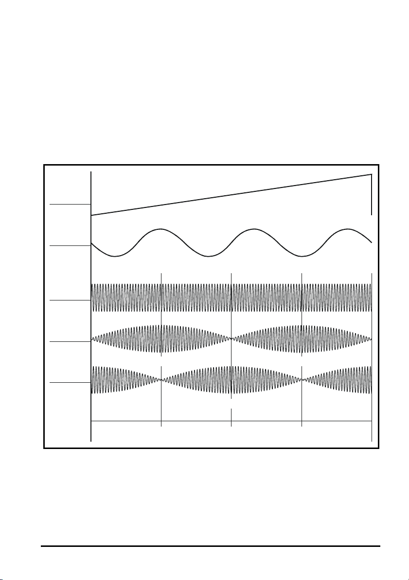
3.5 Operation of a resolver
A resolver is a rotating transformer that produces output voltages on a pair of SIN and
COS secondary windings. When an excitation voltage is applied to the primary winding
and the resolver shaft is rotated, amplitude-modulated voltage waveforms appear on the
secondary windings, where the excitation voltage acts as a carrier for the modulation. In
addition, on each secondary, the phase of the carrier voltage is reversed twice every
revolution.
Figure 3-3 shows the relationships between the resolver position and the SIN and COS
outputs, as well as the phase reversals in the carrier waveforms for forward rotation (for
a clearer indication of the phase reversals, see Figure 3-4). Figure 3-3 also shows the
waveform of the U motor phase for a six-pole motor when the motor and resolver are
aligned for zero phase offset.
Figure 3-3 Sine and Cosine modulation on the secondary windings
Resolver
position
Motor
U phase
Excitation
(primary)
SIN
secondary
COS
secondary
Carrier with excitationin phase
in phase Carrier
with excitation
Zero position Zero position
Carrier with excitationin anti-phaseCarrier
o
90
Carrier with excitationin anti-phase
o
180
270
o
in phase
with excitation
3.5.1 Direction of rotation
Forward rotation is defined as follows:
Motor
Phase sequence: U V W
Resolver
COS modulation leads the SIN modulation (by 90°) (see Figure 3-4)
SM-Resolver User Guide 9
Issue Number: 4 www.controltechniques.com
Page 10
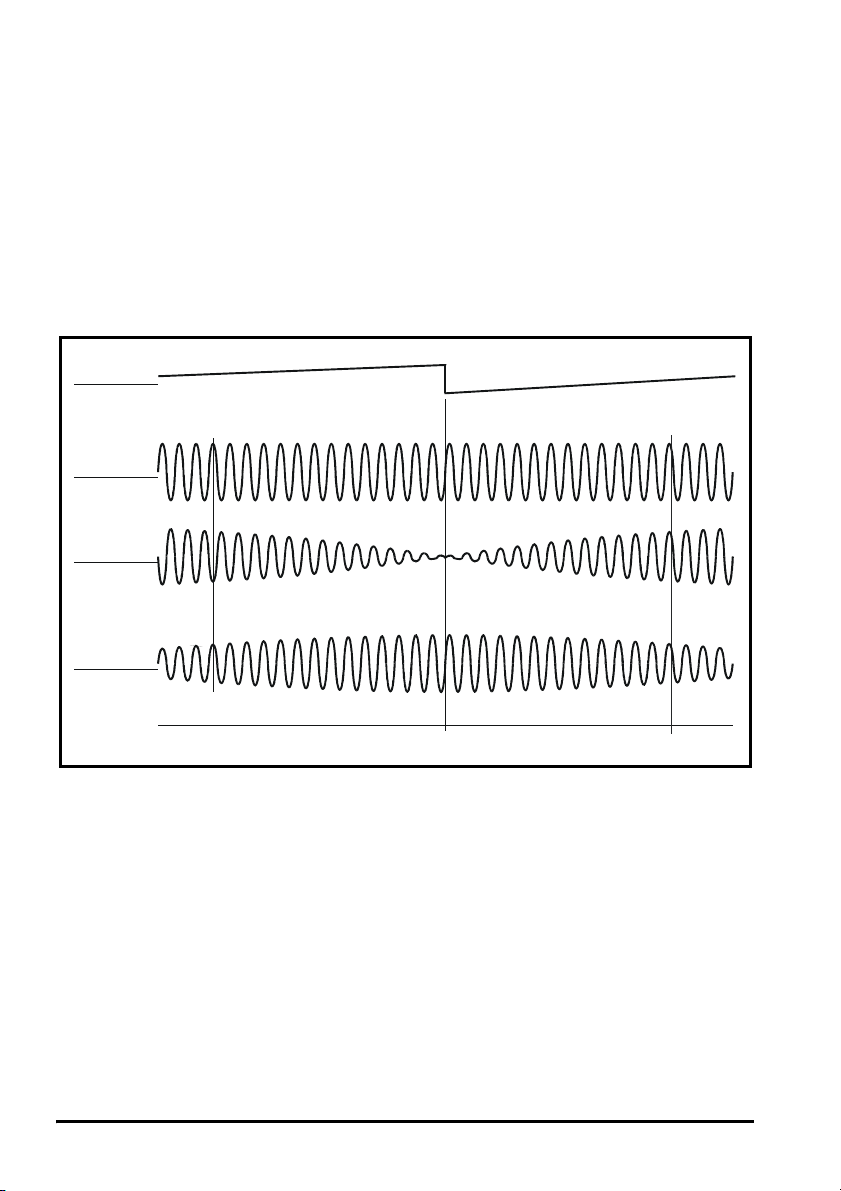
3.5.2 Zero-position point
p
The resolver passes through its zero position when the following occur (see Figure 3-4):
SIN output
• The modulation is at minimum
• The carrier waveform changes from being in anti-phase with the excitation voltage
on the primary to being in phase with the excitation voltage on the primary
COS output
• The modulation is at maximum
• The carrier waveform is in phase with the excitation voltage on the primary
Figure 3-4 Modulation and carrier-phase conditions around the zero position of
the resolver
Resolver
position
Excitation
(primary)
SIN
secondary
COS
secondary
Carrier with excitationin anti-phase
Carrier with excitationin phase
Zero
Carrier with excitationin phase
Carrier with excitationin phase
osition of resolver
10 SM-Resolver User Guide
www.controltechniques.com Issue Number: 4
Page 11
4 Installing the SM-Resolver
e
4.1 Solutions Module slots
Before installing the SM-Resolver, refer to Chapter 2 Safety information on page 5.
WARNING
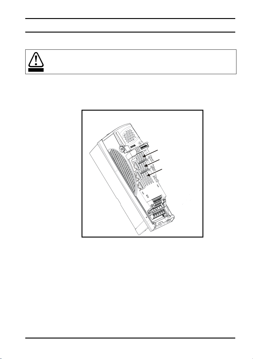
There are three slots available, which the Solutions Module can be plugged into as
shown in Figure 4-1. The Solutions Module can be plugged into either one of these, but
it is recommended that slot 3 be used for the first Solutions Module then slot 2 and slot
1. This ensures maximum mechanical support for the Solutions Module once fitted.
Figure 4-1 Location of slots 1, 2 and 3 on the Unidrive SP
Solutions Module
slot 1 (Menu 15)
Solutions Module
slot 2 (Menu 16)
Solutions Modul
slot 3 (Menu 17)
4.2 Installation
1. Before installing the SM-Resolver in the Unidrive SP, ensure the AC supply has
been disconnected from the drive for at least 10 minutes.
2. Ensure that both the +24V, and +48V backup power supplies are disconnected from
the drive for at least 10 minutes if used.
3. Check that the exterior of the SM-Resolver is not damaged, and that the multi-way
connector is free from dirt and debris.
4. Do not install a damaged or dirty SM-Resolver in the drive.
5. Remove the terminal cover from the drive. (For removal / re-fitting instructions, see
Unidrive SP Solutions Module Installation Sheet provided with the Solutions
Module.)
6. Position the drive connector of the SM-Resolver over the connector of the
appropriate slot in the drive and push downwards until it locks into place.
SM-Resolver User Guide 11
Issue Number: 4 www.controltechniques.com
Page 12
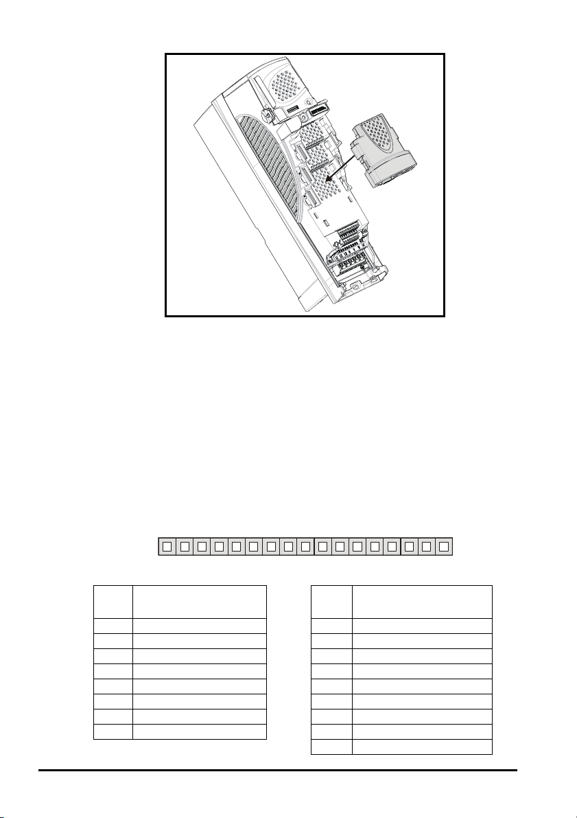
Figure 4-2 Fitting the SM-Resolver
7. Re-fit the terminal cover to the drive. (For removal / re-fitting instructions, see
Unidrive SP Solutions Module Installation Sheet provided with the Solutions
Module.)
8. Connect the AC supply to the drive.
9. Set Pr 0.49 to L2 to unlock read only security.
10. Check that Menu 15 (slot 1), 16 (slot 2), or 17 (slot 3) parameters are now available.
11. Check that Pr 15.01, Pr 16.01 or Pr 17.01 shows the correct code for the SMResolver (code = 101).
12. If the checks in steps 10 and 11 fail, either the SM-Resolver is not fully inserted, or
the Solutions Module is faulty.
13. If a trip code is now present refer to Chapter 7 Diagnostics on page 31.
4.3 Terminal descriptions
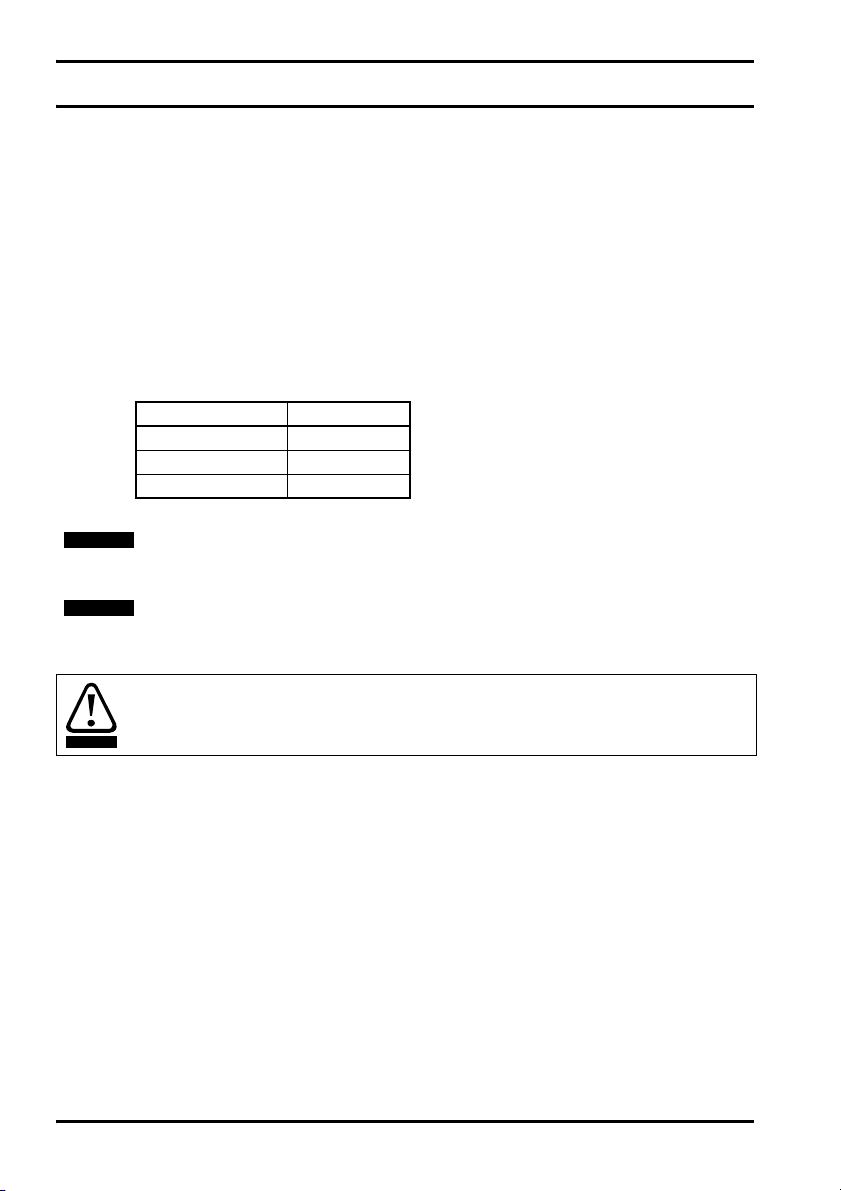
Figure 4-3 SM-Resolver terminals
12345678910 11 12 13 14 15 16 17
Table 4.1 SM-Resolver terminal descriptions
Term Simulated encoder
Term Resolver connections
output connections
1A 9SIN LOW
2 A\ 10 SIN HIGH
30V 11COS LOW
4 B 12 COS HIGH
5 B\ 13 REF HIGH (excitation)
6 0V 14 REF LOW (excitation)
7 Z 15 0V
8Z\ 160V
17 0V
12 SM-Resolver User Guide
www.controltechniques.com Issue Number: 4
Page 13

4.4 Wiring, Shield connections
shield
Shielding considerations are important for PWM drive installations due to the high
voltages and currents present in the output circuit with a very wide frequency spectrum,
typically from 0 to 20 MHz.
The sensitivity of various inputs to electromagnetic disturbance differs with the
introduction of shielding providing good data transfer. Circuits at particular risk are
precision analog inputs, where quite small induced voltages may cause significant
errors, and fast data or encoder inputs where the signal levels are relatively high but the
bandwidth is wide so that very brief excursions may cause errors.
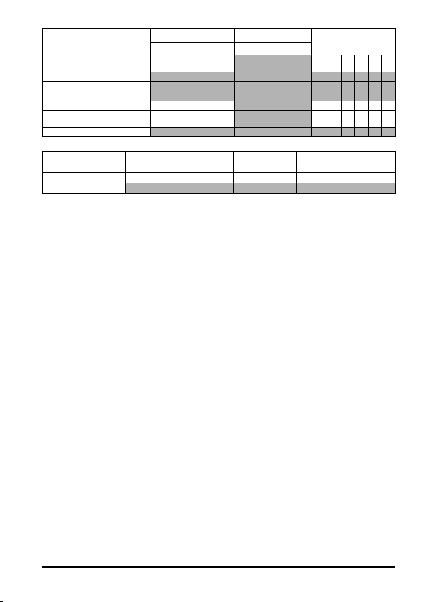
Table 4.2 Feedback Device Properties
Input Type Nature Wiring Requirement
Resolver Inputs
Encoder Inputs
Data links/
comms port
It is also necessary to provide the correct shielding arrangement in order to meet the
radiated emission requirements of EMC standards.
4.4.1 Functional shielding requirements
These requirements are necessary to ensure the correct transfer of data from the
resolver to the drive.
Figure 4-4 Functional shielding requirements
Twisted pair
shield and
overall shield
connected
to 0V
Medium bandwidth e.g. 10kHz,
sensitive
Wide bandwidth e.g. 500kHz.
Good immunity but limited
common mode range
Wide bandwidth for advanced
communications systems, e.g.
500kHz to 10MHz.
Good immunity but limited
common mode range.
Twisted
pair
shield
Shielding recommended
Correct shielding arrangement essential.
Matched cable and correct termination
recommended.
Correct shielding arrangement essential/
Matched cable and correct termination
recommended with no discontinuity.
Twisted
pair
Cable
shield
Connection at
SM-Resolver
Cable
shield
Cable
Resolver
Note that the resolver provides inherent galvanic isolation of the signal connections from
ground. This means that no special provisions are required in order to provide surge
immunity for cables exceeding 30m.
SM-Resolver User Guide 13
Issue Number: 4 www.controltechniques.com
Page 14

4.4.2 Compliance with generic emission standards
g
p
In this case the outer cable shield must be clamped to ground at the drive end using the
grounding bracket, as shown in the EMC section of the Unidrive SP User guide. It is
recommended that the overall shield is not connected to 0V.
Figure 4-5 Shielding for compliance with generic emission standards
Grounding
bracket
Overall shield clamped
to ground using the
rounding bracket
Twisted pair
shield only
connected
to 0V
Connection at
SM-Resolver
Cable
shield
Twisted
pair
shield
4.4.3 Recommended cable
The recommended cable for feedback signals is a twisted pair, shielded with an overall
shield type as shown below.
Figure 4-6 Feedback Cable, Twisted Pair
Cable overall shield
Twisted
pair
cable
Cable
Cable
Twisted
pair
shield
Cable
shield
Resolver
air shield
Twisted
NOTE
Ensure that feedback cables are kept as far away as possible from power cables and
avoid parallel routing.
14 SM-Resolver User Guide
www.controltechniques.com Issue Number: 4
Page 15

5 Getting started
5.1 Installation
The control circuits are isolated from the power circuits in the drive by basic insulation
only, as specified in IEC60664-1. The installer must ensure that the external control
WARNING
circuits are insulated from human contact by at least one layer of insulation rated for use
at the AC supply voltage.
If the control circuits are to be connected to other circuits classified as Safety Extra Low
Voltage (SELV) (e.g. to a personal computer) an additional isolating barrier must be
included in order to maintain the SELV classification.
Resolver feedback is transmitted from a resolver as low voltage analog signals. Ensure
that electrical noise from the drive or motor does not adversely affect the resolver
feedback. Ensure that the drive and motor are connected as per the instructions given in
Chapter 4 Electrical Installation in the Unidrive SP User Guide, and that the resolver
feedback wiring and shielding recommendations are followed in section 4.4 Wiring,
Shield connections on page 13.
SM-Resolver User Guide 15
Issue Number: 4 www.controltechniques.com
Page 16

5.2 Solutions Module set-up
Action Detail
Ensure:
Before power-up
Power-up the drive
Slot identification
Set-up the operating
resolution and
variable maximum
speed limit
Set-up resolver
excitation voltage
Set-up the resolver
number of poles
Enable SM-Resolver
• Drive enable signal is not given (terminal 31)
• Solutions Module is fitted in appropriate slot
• Resolver is connected to the SM-Resolver
Ensure:
• Encoder Phase Error Detect is disabled (Pr
• Module error detectionis set-up as required (Pr
• Drive displays ‘inh’
If the drive trips, see Chapter 7 Diagnostics on page 31.
Identify which Solutions Module slot and associated menu are being used:
• Slot 1 – Menu 15
• Slot 2 – Menu 16
• Slot 3 – Menu 17
Enter the equivalent number of lines per revolution in Pr x.10:
Max speed of motor
(2-pole resolver)
0 to 3,300 rpm 14 bit 4,096
3,300.1 to 13,200 rpm 12 bit 1,024
13,200.1 to 40,000 rpm 10 bit 256
Set-up the correct excitation voltage for resolver:
• Turns ratio 3:1 (6V rms excitation), set Pr x.13 = 0
• Turns ratio 2:1 (4V rms excitation), set Pr x.13 = 2
Set-up the resolver number of poles:
• 2-pole set Pr x.15 = 0 (default setting)
• 4-pole set Pr x.15 = 1
• 6-pole set Pr x.15 = 2
• 8-pole set Pr x.15 = 3
Enable the SM-Resolver as the drive position / speed feedback by setting
Pr 3.26 to Slot1 (1), Slot2 (2) or Slot3 (3) depending on the location of the
Solutions Module.
Operating
resolution
3.40
= 0) to prevent Enc2 trip
x.17
)
Equivalent resolution in
encoder lines per
revolution (Pr x.10)
16 SM-Resolver User Guide
www.controltechniques.com Issue Number: 4
Page 17

5.3 Encoder simulation output
The SM-Resolver provides a simulated encoder output with this being configured for a
1024 line quadrature output at default. The source of the output can be selected by
parameter configuration (Pr x.24), as either the resolver itself or the drive main encoder
(EIA485 encoder only).
Table 5.1
Simulation based upon the resolver Simulation based upon the drive encoder
Outputs are to EIA485 specification.
Maximum output frequency of 500kHz
Simulated outputs are generated in hardware.
Output format: Quadrature with marker-pulse
(A, B, Z).
Scaling of the output is available in order to
reduce the number of lines per revolution (to a
minimum of 128) in defined steps as shown
below:
Pr x.25 Ratio
0.0000 to 0.0312 1/32
0.0313 to 0.0625 1/16
0.0626 to 0.1250 1/8
0.1251 to 0.2500 1/4
0.2501 to 0.5000 1/2
0.5001 to 3.0000 1
A marker pulse will be generated when the
resolver is at the zero position. Both A and B
are low in the zero position.
The width of the marker pulse is determined by
the operating resolution of the resolver, not the
resolution of the encoder simulation output.
The minimum marker pulse width is 300ns
Simulated outputs are a buffered version of the
EIA485 inputs of the drive encoder
Scaling is not possible.
The marker pulse is a buffered version of the Z
input of the drive encoder.
5.4 Freeze function
The SM-Resolver has a freeze function, but does not have freeze inputs. The freeze
function can be activated by the SM-Applications or SM-Universal Encoder Plus. When
a freeze signal is provided, the freeze flag (Pr x.39) is set to "ON". When activated, the
non-marker position (Pr x.30) is transferred into the freeze position (Pr x.36).
The freeze flag does not re-set itself. Before carrying out consecutive freeze functions,
the freeze flag must be cleared by the user (Pr x.39 = "OFF") on both the SM-Resolver,
the source of the freeze, and any additional associated Solutions Module..
NOTE
SM-Resolver User Guide 17
Issue Number: 4 www.controltechniques.com
A 4-pole resolver will give two electrical cycles within one mechanical revolution.
Therefore, a 4-pole resolver cannot provide absolute position (mechanical). Similarly, a
6-pole or 8-pole resolver cannot provide absolute position (mechanical).
It is for this reason that the freeze function does not operate with a resolver that has 4, 6
or 8 poles.
Page 18
6 Parameters
6.1 Introduction
The parameters listed in this chapter are used for programming and monitoring the SMResolver.
The SM-Resolver is classed as a dumb module as it does not have its own processor
and as a result all parameters are updated by the drive processor.
The SM-Resolver parameters are read/written by the drive background task or at the
combined update time for time critical parameters. The combined update time depends
on the number and type of dumb modules fitted to the drive. For each dumb module the
update rate of these parameters is specified as either 4 or 8ms. The combined update
time is the total of the update times for all dumb modules fitted. (E.g. if two modules with
4ms and 8ms update times are fitted to the drive, then the combined update time for the
time critical parameters of each module will be 12ms.)
Dumb module Update time
SM-I/O Plus 8ms
SM-Encoder Plus 4ms
SM-Resolver 4ms
NOTE
NOTE
WARNING
The same parameter structure is available in menu 15, 16 and 17 referring to slots 1, 2
and 3.
Parameter changes for the SM-Resolver will only take effect when the drive is not
enabled.
Before attempting to adjust any parameters, refer to Chapter 2 Safety information on
page 5.
18 SM-Resolver User Guide
www.controltechniques.com Issue Number: 4
Page 19

Table 6.1 Key to parameter coding
Coding Attribute
RW Read/write: can be written by the user
RO Read only: can only be read by the user
Bit 1 bit parameter
Bi Bipolar parameter
Uni Unipolar parameter
Txt Text: the parameter uses text strings instead of numbers.
Filtered: some parameters which can have rapidly changing
FI
values are filtered when displayed on the drive keypad for
easy viewing.
Destination: indicates that this parameter can be a
DE
destination parameter.
Rating dependant: this parameter is likely to have different
values and ranges with drives of different voltage and
current ratings. This parameters is not transferred by smart
RA
cards when the rating of the destination drive is different
from the source drive.
Not cloned: not transferred to or from smart cards during
NC
cloning.
PT Protected: cannot be used as a destination.
User save: saved in drive EEPROM when the user initiates
US
a parameter save.
Power-down save: automatically saved in drive EEPROM
PS
at power-down.
SM-Resolver User Guide 19
Issue Number: 4 www.controltechniques.com
Page 20

6.2 Single line descriptions
Ú) Default(Ö)
Parameter
x.01 Solutions Module ID 0 to 599 101 RO Uni PT US
x.02 No function
x.03 Speed feedback ±40,000.0 rpm RO Bi FI NC PT
x.04 Revolution counter 0 to 65,535 revolutions
x.05 Position
x.06 No function
x.07 No function
x.08 No function
x.09 No function
Equivalent lines per
x.10
revolution
x.11 No function
x.12 No function
x.13 Resolver excitation 3:1 (0), 2:1 (1 or 2) 3:1 (0) RW Uni US
x.14 No function
x.15 Resolver poles
x.16 No function
x.17 Error detection level 0 to 7 1 RW Uni US
x.18 No function
x.19 Feedback filter 0 to 5 (0 to 16 ms) 0 RW Uni US
x.20 No function
x.21 No function
x.22 No function
x.23 No function
x.24 Encoder simulation source Pr 0.00 to Pr 21.51 Pr 0.00 RW Uni PT US
Encoder simulation ratio
x.25
numerator
x.26 No function
x.27 No function
x.28 No function
Non-marker reset
x.29
revolution counter
x.30 Non-marker reset position
x.31 No function
x.32 No function
x.33 No function
x.34 No function
x.35 No function
x.36 Freeze position
x.37 No function
x.38 No function
x.39 Freeze flag OFF (0) or On (1) OFF (0) RW Bit NC
x.40 No function
x.41 No function
x.42 No function
x.43 No function
x.44 No function
Range(
OL CL OL VT SV
16
0 to 65,535 (1/2
revolution)
0 to 50,000 4,096 RW Uni US
2POLE (0), 4POLE (1),
6POLE (2),
8POLE (3 to 11)
0.0000 to 3.0000 1.0000 RW Uni US
0 to 65,535 revolutions RO Uni NC PT
0 to 65,535 (1/2
revolution)
0 to 65,535 (1/2
revolution)
ths of a
16
ths of a
16
ths of a
2POLE (0) RW Uni US
Type
RO Uni FI NC PT
RO Uni FI NC PT
RO Uni NC PT
RO Uni NC PT
20 SM-Resolver User Guide
www.controltechniques.com Issue Number: 4
Page 21
Ú) Default(Ö)
Parameter
Position feedback
x.45
initialised
x.46 No function
x.47 No function
x.48 No function
x.49 Lock position feedback OFF (0) or On (1) RW Bit
Solutions Module error
x.50
status
x.51 No function
RW Read / Write RO Read only Uni Unipolar Bi Bi-polar
Bit Bit parameter Txt Text string FI Filtered DE Destination
NC Not cloned RA Rating dependent PT Protected US User save
PS Power down save
Range(
OL CL OL VT SV
OFF (0) or On (1) RO Bit NC PT
0 to 255
Typ e
RO Uni NC PT
SM-Resolver User Guide 21
Issue Number: 4 www.controltechniques.com
Page 22
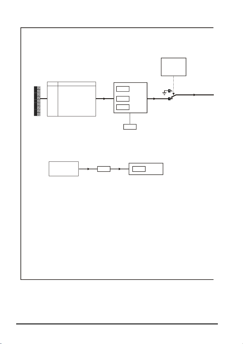
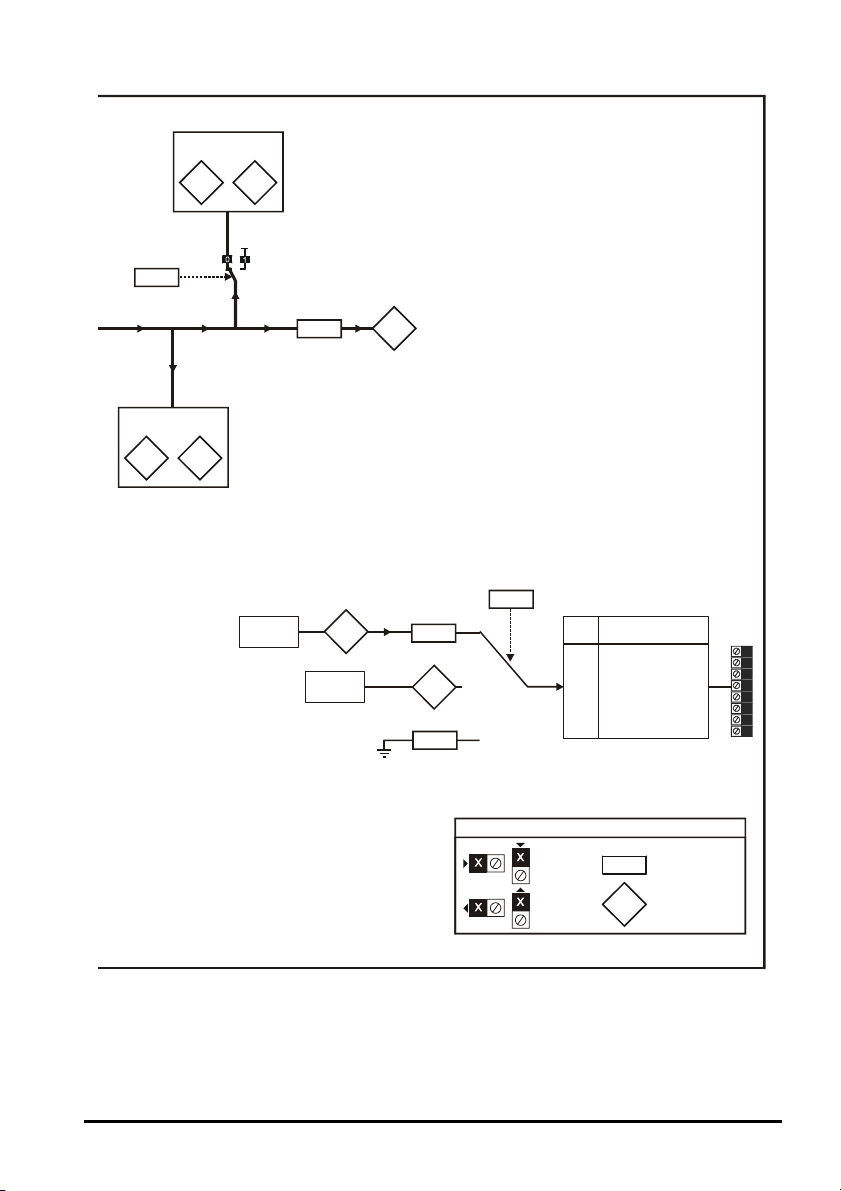
Figure 6-1 SM-Resolver logic diagram
Resolver
selected as
drive feedback
(Pr )
3.26
Term Resolver connections
9 SIN LOW
10 SIN HIGH
11 COS LOW
12 COS HIGH
13 REF H IGH (excitation)
14 REF LOW (excitation)
15 0V
16 0V
17 0V
Freeze input
SM-Applications
SM-Universal
Encoder Plus
Freeze
flag
x.39
Equivalent
x.10
lines per
revolution
Resolver
x.13
excitation
Resolver
x.15
poles
x.17
Error detection
level
Freeze positional
x.36
information
Freeze
position
22 SM-Resolver User Guide
www.controltechniques.com Issue Number: 4
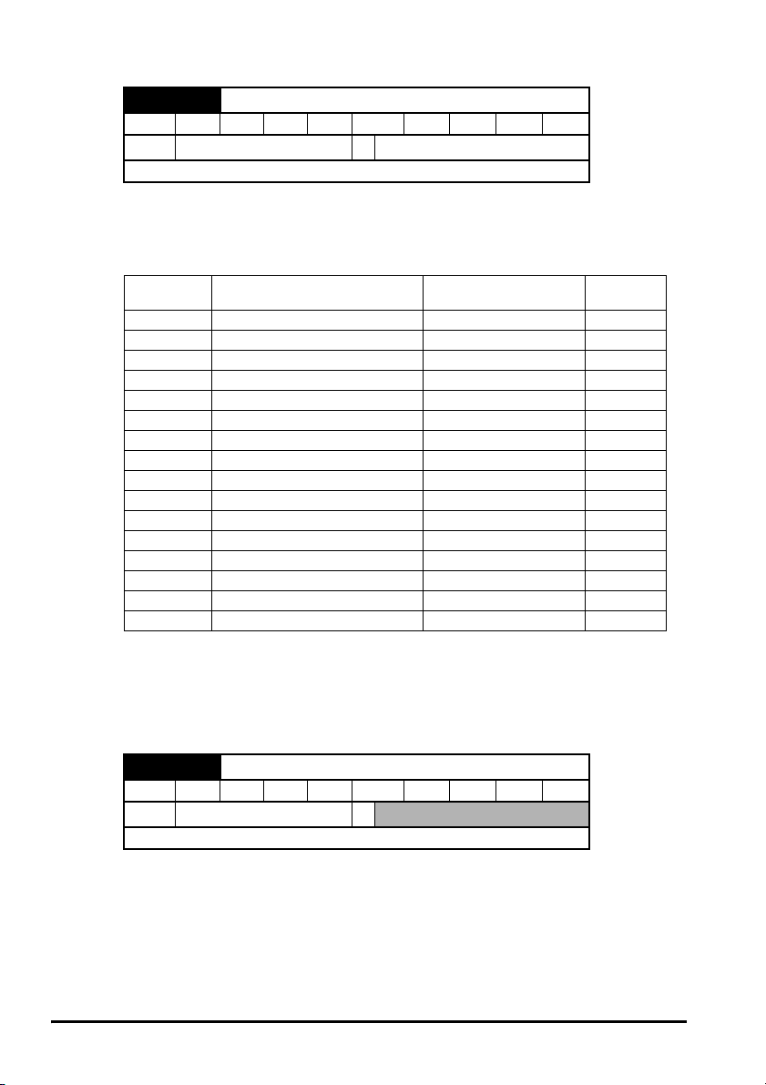
Page 23
Lock position
feedback
x.49
Positional information
Revolution
Position
counter
x.04 x.05
Feedback
filter
x.19
Speed
feedback
x.03
Revolution
positional information
Position
counter
x.29 x.30
Non marker reset
Resolver
source
Position
x.05
Encoder
source
Ratio
numerator
x.25
3.29
x.xx
Encoder
simulation
source
x.24
Simulated encoder
Ter m
output connections
1
2
3
4
5
6
7
8
Input
terminals
Output
terminals
The parameters are all shown at their default settings
Key
0.XX
0.XX
A
A\
0V
B
B\
0V
Z
Z\
Read-write (RW)
parame ter
Read-only (RO)
parame ter
SM-Resolver User Guide 23
Issue Number: 4 www.controltechniques.com
Page 24
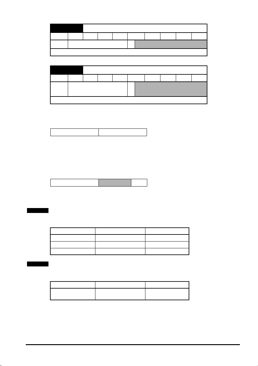
6.3 Parameter descriptions
x.01 Solutions Module ID code
RO Uni PT US
Ú
Update rate: Write on power-up
The menu for the relevant slot appears for the new Solutions Module category with the
default parameter values for the new category. When no Solutions Module is fitted in the
relevant slot this parameter is zero. When a Solutions Module is fitted this parameter
displays the identification code as shown below.
0 to 599
Ö
101
Code Solutions Module Category
0 No Solutions Module fitted
101 SM-Resolver Feedback 9
102 SM-Universal Encoder Plus Feedback
104 SM-Encoder Plus Feedback 9
201 SM-I/O Plus Automation 9
301 SM-Applications Automation
302 SM-Application Lite Automation
401 reserved Fieldbus
402 reserved Fieldbus
403 SM-Profibus DP Fieldbus
404 SM-Interbus Fieldbus
405 reserved Fieldbus
406 SM-CAN Fieldbus
407 SM-DeviceNet Fieldbus
408 SM-CANopen Fieldbus
501 SM-SLM SLM
Dumb
module
The new parameters values are not stored in EEPROM until the user performs a
parameter save. When parameters are saved by the user in the drive EEPROM the
option code of the currently fitted Solutions Module is saved in EEPROM. If the drive is
subsequently powered-up with a different Solutions Module fitted, or no Solutions
Module fitted where one was previously fitted, the drive gives a Slot.dF or SLot.nf trip.
x.03 Speed feedback
RO Bi FI NC PT
Ú
±40,000.0 rpm
Ö
Update rate: 4ms x number of dumb modules
Provided the set-up parameters for the position feedback are correct this parameter
shows the speed in rpm.
24 SM-Resolver User Guide
www.controltechniques.com Issue Number: 4
Page 25
x.04 Revolution counter
RO Uni FI NC PT
0 to 65,535 revolutions
Ú
Ö
Update rate: 4ms x number of dumb modules
x.05 Position
RO Uni FI NC PT
0 to 65,535 (1/216ths
Ú
revolutions)
Ö
Update rate: 4ms x number of dumb modules
16
Pr x.04 and Pr x.05 give the position with a resolution of 1/2
ths of a revolution as a 32
bit number as shown below.
31 16 15 0
Revolutions Position
Provided the set-up parameters are correct, the position is always converted to units of
16
1/2
ths of a revolution, but some parts of the value may not be relevant depending on
the resolution of the feedback device. For example if 10 bit resolution is selected the
resolver produces 4,096 counts per revolution, and so the position is represented by the
bits in the shaded area only.
31 16 15 4 3 0
Revolutions
Position
When the feedback device rotates by more than one revolution, the revolutions in Pr
x.04 increment or decrement in the form of a sixteen bit roll-over counter.
NOTE
The internal update time for the position Pr x.03 and Pr x.05 when used as feedback runs
at level 1, this being switching frequency dependant as follows.
Update time Switching frequency Level
167µs3kHz 1
125µs 4kHz, 8kHz, 16kHz 1
83µs 6kHz, 12kHz 1
NOTE
The internal update time for the speed Pr x.03 when used as feedback runs at level 2 as
follows.
Update time Switching frequency Level
250µs
3kHz, 4kHz, 6kHz,
8kHz, 12kHz, 16kHz
2
SM-Resolver User Guide 25
Issue Number: 4 www.controltechniques.com
Page 26

x.10 Equivalent lines per revolution
RW Uni US
Ú
0 to 50,000
Ö
4,096
Update rate: Background read
This parameter relates to the equivalent lines per revolution of a quadrature encoder
that would provide same resolution of feedback. This parameter should only be set to
256 (10 bit resolution), 1,024 (12 bit resolution) or 4,096 (14 bit resolution). If the
parameter is set to any other value the drive assumes the following: 32 to 256 = 256;
257 to 1,024 = 1,024; 1,025 to 50,000 = 4,096. If the drive is operating in Closed-loop
vector or Servo modes and the resolver is selected to provide speed feedback for the
drive (see Pr 3.23) then variable maximum SPEED_LIMIT_MAX is defined in the
following table.
Resolver poles
(Pr x.15)
2 4,096 14 3,300.0
2 1,024 12 13,200.0
2 256 10 40,000.0
4 4,096 14 1,650.0
4 1,024 12 6,600.0
4 256 10 26,400.0
6 4,096 14 1,100.0
6 1,024 12 4,400.0
6 256 10 17,600.0
8 4,096 14 825.0
8 1,024 12 3,300.0
8 256 10 13,200.0
Equivalent lines per
revolution (Pr x.10)
Operating
resolution (bit)
SPEED_LIMIT_MAX
x.13 Resolver excitation
RW Uni US
Ú
3:1 (0), 2:1 (1 or 2)
Ö
3:1 (0)
Update rate: Background read
The excitation level can be controlled for use with 3:1 ratio resolvers (Pr x.13 = 0), or 2:1
ratio resolvers (Pr x.13 = 1 or 2).
26 SM-Resolver User Guide
www.controltechniques.com Issue Number: 4
Page 27

x.15 Resolver poles
RW Uni US
2POLE (0), 4POLE (1),
6POLE (2), 8POLE (3 to
Ú
Ö
2POLE (0)
11)
Update rate: Background read
Resolvers with the following numbers of poles can be used with the Solutions Module.
0: 2POLE
1: 4POLE
2: 6POLE
3 to 11: 8POLE
A 2 pole resolver can be selected as drive speed feedback with a motor with any
number of poles. A resolver with a number of poles greater than 2 can only be used with
a motor with the same number of poles. If the number of resolver poles is set up
incorrectly and the resolver is selected as the drive speed feedback for motor control
Solutions Module error 11 is produced.
x.17 Error detection level
RW Uni US
Ú
0 to 7
Ö
1
Update rate: Background read
Trips can be enabled/disabled using Pr x.17 as follows:
Bit Function
0 Wire break detect
1 Not used
2 Not used
The binary sum defines the level of error detection as below:
Bit 2 Bit 1 Bit 0 Error detection level Value in Pr x.17
0 0 0 Error detection disabled 0
0 0 1 Wire break detect 1
0 1 0 Error detection disabled 2
0 1 1 Wire break detect 3
1 0 0 Error detection disabled 4
1 0 1 Wire break detect 5
1 1 0 Error detection disabled 6
1 1 1 Wire break detect 7
NOTE
The wire break trip is not activated provided one signal is >1.5Vrms or both are >0.2Vrms
approximately.
SM-Resolver User Guide 27
Issue Number: 4 www.controltechniques.com
Page 28

x.19 Feedback filter
RW Uni US
Ú
0 to 5 (0 to 16 ms)
Ö
0
Update rate: Background read
A sliding window filter may be applied to the feedback. This is particularly useful in
applications where the feedback is used to give speed feedback for the speed controller
and where the load includes a high inertia, and so the speed controller gains are very
high. Under these conditions, without a filter on the feedback, it is possible for the speed
loop output to change constantly from one current limit to the other and lock the integral
term of the speed controller. The filter is not active if the parameter value is 0 or 1ms,
but operates over the defined window for parameter values of 2, 4, 8 and 16ms.
Value in Pr x.19 Filter window
0 Not active
1 Not active
22ms
34ms
48ms
516ms
x.24 Encoder simulation source
RW Uni PT US
Ú
Pr 0.00 to Pr 21.51
Ö
Pr 0.00
Update rate: Background read
x.25 Encoder simulation ratio numerator
RW Uni US
Ú
0.0000 to 3.0000
Ö
1.0000
Update rate: Background read
Pr x.24 = Pr x.05
Encoder simulation output is derived from the resolver input via hardware. The
resolution multiplier can be set up using Pr x.25 as shown in the table below. The
marker output is active when the resolver position is zero, therefore the marker pulse
width is equivalent to one encoder count if the ratio is 1, but is reduced if the ratio is less
than 1.
NOTE
Some ratios are not possible when the resolver resolution is reduced below 14 bits as
shown in the table below.
Pr x.25
0.0000 to 0.0312 1/32 1/8 1/2
0.0313 to 0.0625 1/16 1/8 1/2
0.0626 to 0.1250 1/8 1/8 1/2
0.1251 to 0.2500 1/4 1/4 1/2
0.2501 to 0.5000 1/2 1/2 1/2
0.5001 to 3.0000 1 1 1
Resolver resolution
14 bit 12 bit 10 bit
28 SM-Resolver User Guide
www.controltechniques.com Issue Number: 4
Page 29

Pr x.24 = Pr 3.29
Encoder simulation output is derived from the drive encoder port via hardware from the
A, B and Z inputs. The drive encoder signals must be digital and not SINCOS. No ratio
is possible, therefore Pr x.25 has no effect.
If Pr x.24 has any value than those above the encoder simulation outputs are not active.
x.29 Non-marker reset revolution counter
RO Uni NC PT
0 to 65,535 revolutions
Ú
Update rate: 4ms x number of dumb modules
x.30 Non-marker reset position
RO Uni NC PT
0 to 65,535 (1/216ths of a
Ú
Update rate: 4ms x number of dumb modules
Pr x.29 and Pr x.30 are duplicates of Pr x.04 and Pr x.05 respectively.
x.36 Freeze position
RO Uni NC PT
Ú
Update rate: 4ms x number of dumb modules
revolution)
0 to 65535 (1/216ths of a
revolution)
Ö
Ö
Ö
x.39 Freeze flag
RW Bit NC
Ú
Update rate: 4ms x number of dumb modules
This Solutions Module does not have its own freeze input, therefore the freeze input
must come from a SM-Applications or SM-Universal Encoder Plus. The freeze data is
processed every 4ms x number of dumb modules fitted. If a freeze has occurred and the
freeze flag (Pr x.39) is zero, the position is stored in Pr x.36 and the freeze flag is set.
The freeze flag must be reset by the user before the next freeze event is stored. This
function is only active with 2 pole resolvers.
RO Bit NC PT
Ú
Update rate: Background write
At power-up Pr x.45 is initially OFF (0), but is set to On (1) when the SM-Resolver can
provide position feedback. Pr x.45 then remains at On (1) whilst the drive is poweredup.
SM-Resolver User Guide 29
Issue Number: 4 www.controltechniques.com
OFF (0) or On (1)
x.45 Position feedback initialised
OFF (0) or On (1)
Ö
Ö
OFF (0)
Page 30

x.49 Lock position feedback
RW Bit
Ú
Update rate: Background write
If Pr x.49 is set to one, Pr x.04 and Pr x.05 are not updated. If this parameter is zero, Pr
x.04 and Pr x.05 are updated normally.
RO Uni NC PT
Ú
Update rate: Background write
The error status is provided so that the only one option error trip is required for each
Solutions Module slot. If an error occurs, the reason for the error is written to this
parameter and the drive may produce a ‘SLX.Er’ trip, where x is the slot number. A
value of zero indicates that the Solutions Module has not detected an error, a non-zero
value indicates that an error has been detected. (See Chapter 7 Diagnostics for the
meaning of the values in this parameter.) When the drive is reset, this parameter is
cleared.
This Solutions Module includes a temperature monitoring circuit. If the PCB temperature
exceeds 90°C, the drive fan is forced to operate at full speed (for a minimum of 10s). If
the temperature falls below 90°C, the fan can operate normally again. If the PCB
temperature exceeds 100°C, the drive is tripped and the error status is set to 74.
OFF (0) or On (1)
x.50 Solutions Module error status
0 to 255
Ö
Ö
30 SM-Resolver User Guide
www.controltechniques.com Issue Number: 4
Page 31

7 Diagnostics
S
S
If the drive trips, the output is disabled so that the drive stops controlling the motor. The
lower display indicates that a trip has occurred and the upper display shows the trip.
Trips are listed alphabetically in Table 7.1 based on the trip indication shown on the
drive display. Refer to Figure 7-1.
If a display is not used, the drive LED Status indicator will flash if the drive has tripped.
Refer to Figure 7-2.
The trip indication can be read in Pr 10.20 providing a trip number.
7.1 Displaying the trip history
The drive retains a log of the last 10 trips that have occurred in Pr 10.20 to Pr 10.29 and
the corresponding time for each trip in Pr 10.43 to Pr 10.51. The time of the trip is
recorded from the powered-up clock (if Pr 6.28 = 0) or from the run time clock (if Pr 6.28
= 1).
Pr 10.20 is the most recent trip, or the current trip if the drive is in a trip condition (with
the time of the trip stored in Pr 10.43). Pr 10.29 is the oldest trip (with the time of the trip
stored in Pr 10.51). Each time a new trip occurs, all the parameters move down one,
such that the current trip (and time) is stored in Pr 10.20 (and Pr 10.43) and the oldest
trip (and time) is lost out of the bottom of the log.
If any parameter between Pr 10.20 and Pr 10.29 inclusive is read by serial
communications, then the trip number in Table 7-1 is the value transmitted.
Figure 7-1 Keypad status modes
tatus Mode
Healthy Status
Figure 7-2 Location of the status LED
Trip Statu sAlarm Status
Drive status
= tripped
Trip type (UU
= undervolts)
tatus LED
SM-Resolver User Guide 31
Issue Number: 4 www.controltechniques.com
Non flashing:
Normal status
Flashing:
Trip status
Page 32

Any trip can be initiated by writing the relevant trip number to Pr 10.38. If any trips
shown as user trips are initiated the trip string is "txxx", where xxx is the trip number.
Trips can be reset after 1.0s if the cause of the trip has been rectified.
A full list of drive trips can be found in the Unidrive SP User Guide.
Table 7.1 Trip codes
Trip Diagnosis
C.Optn
SMARTCARD trip: Solutions Modules fitted are different between source drive
and destination drive
1. Ensure correct Solutions Modules are fitted
180
2. Ensure Solutions Modules are in the same Solutions Module slot
3. Reset the drive
SL.rtd
Solutions Module trip: Solutions Module has failed to recognise that the drive
operating mode has changed
1. Ensure Solutions Module is fitted correctly
215
2. Contact the supplier of the Solutions Module
SLX.dF Solutions Module slot X trip: Solutions Module type fitted in slot X changed
204,209,
SLX.Er
202, 207,
Save parameters and reset the drive
214
Solutions Module slot X trip: Error detected with Solutions Module, where X is
the slot number
If the drive trips SLX.Er, Pr x.50 will display the error code. An explanation of all error
codes is given below:
212
Pr x.50 Fault description
0 No errors
1 Supply short circuit
The wire break detection looks at the SIN and COS signals and expects one signal
to be above the high threshold when the other is below the low threshold, or for
2*
both signals to be in-between the threshold values. If the above conditions are not
satisfied, an error code 2 is produced.
The number of poles of the resolver is greater than 2, but is different to the number
11
of poles of the motor.
74 Solutions Module overtemperature.
*This trip can be enabled/disabled by Pr x.17.
When the drive is reset Pr x.50 is cleared.
SLX.HF Solutions Module slot X trip: Solutions Module X hardware fault
200,205,
1. Ensure Solutions Module is fitted correctly
210
2. Contact the supplier of the Solutions Module
SLX.nF Solutions Module slot X trip: Solutions Module has been removed
1. If the Solutions Module has been purposely removed from the drive, save
203,208,
213
parameters and reset the drive.
2. Ensure Solutions Module is fitted correctly
3. Replace Solutions Module
4. Save parameters and reset drive
NOTE
The SM-Resolver will only provide speed and position feedback when it is selected as
the source of the drive speed/position feedback. Hence the SM-Resolver does not
function when the drive is operating in open-loop mode.
32 SM-Resolver User Guide
www.controltechniques.com Issue Number: 4
Page 33
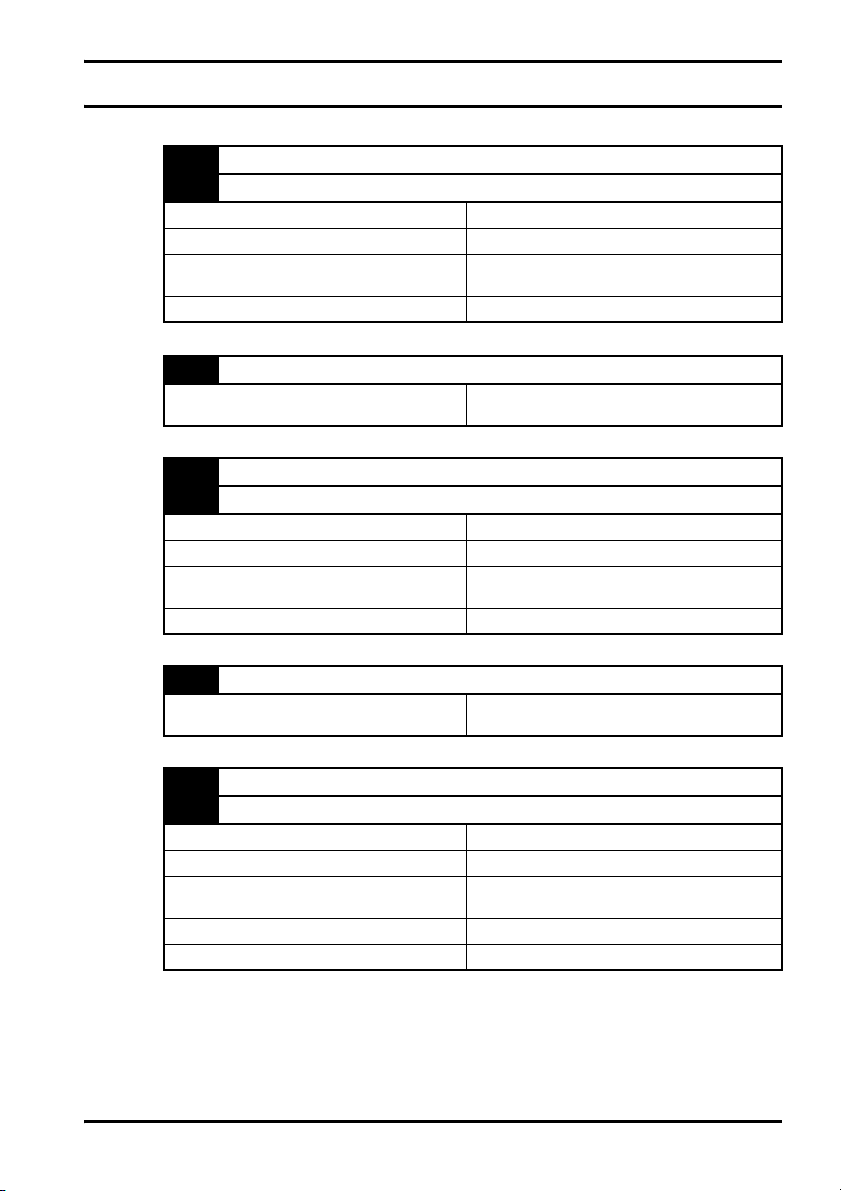
8Terminal data
Simulated encoder output channel A
1
Simulated encoder output channel A\
2
Type EIA485 differential voltage
Maximum frequency 500kHz
Absolute maximum applied voltage relative to
0V
Protection Current limit with thermal protection
0V
3
Total current for all 0V terminals of Solutions
Module
Simulated encoder output channel B
4
Simulated encoder output channel B\
5
Type EIA485 differential voltage
Maximum frequency 500kHz
Absolute maximum applied voltage relative to
0V
Protection Current limit with thermal protection
±14V
200mA
±14V
0V
6
Total current for all 0V terminals of Solutions
Module
Simulated encoder output channel Z
7
Simulated encoder output channel Z\
8
Type EIA485 differential voltage
Maximum frequency 500kHz
Absolute maximum applied voltage relative to
0V
Minimum marker pulse width 300ns
Protection Current limit with thermal protection
200mA
±14V
SM-Resolver User Guide 33
Issue Number: 4 www.controltechniques.com
Page 34

Resolver input SIN LOW
9
Resolver input SIN HIGH
10
Resolver input COS LOW
11
Resolver input COS HIGH
12
Type 2V rms (max) sinusoidal signal
Operating frequency 6kHz
Absolute maximum applied DC voltage (SIN
LOW or COS LOW) to 0V
Absolute maximum applied DC voltage (SIN
HIGH or COS HIGH) to 0V
Protection Series resistors and clamp diodes
Resolver excitation REF HIGH
13
Resolver excitation REF LOW
14
Type
Maximum load (minimum impedance) 85Ω
Nominal voltage
Absolute maximum applied DC voltage (REF
HIGH) with reference to 0V
Absolute maximum applied current (REF LOW) 200mA
Protection Over-current protection
±2.5V
±12V
6kHz sine wave synchronised to drive control
loops
6V rms (turns ratio = 3:1)
4V rms (turns ratio = 2:1)
±36V
0V
15
0V
16
0V
17
Total current for all 0V terminals of Solutions
Module
200mA
34 SM-Resolver User Guide
www.controltechniques.com Issue Number: 4
Page 35

Index
C
Cautions ....................................................................................................... 5
Colour coding ............................................................................................... 7
Compliance ............................................................................................ 6, 14
D
Diagnostics ................................................................................................. 31
E
Electrical noise ........................................................................................... 15
Electrical safety ............................................................................................ 5
Encoder simulation output .......................................................................... 17
Environmental limits ..................................................................................... 6
Error detection level ...................................................................................27
Error status ................................................................................................. 30
F
Features ....................................................................................................... 7
Feedback cable .......................................................................................... 14
Feedback filter ............................................................................................ 28
Freeze function .......................................................................................... 17
G
Grounding bracket ...................................................................................... 14
I
Identification of Solutions Module ................................................................ 7
Installation ............................................................................................ 11, 15
Internal update time ................................................................................... 25
K
Keypad status modes ................................................................................. 31
L
Logic diagram ............................................................................................. 22
M
Marker ........................................................................................................ 17
Maximum speed ......................................................................................... 16
N
Notes ............................................................................................................ 5
O
Operating resolution ................................................................................... 26
Operation of a resolver ................................................................................. 9
SM-Resolver User Guide 35
Issue Number: 4 www.controltechniques.com
Page 36

P
Parameter - single line descriptions ...........................................................20
Parameter coding .......................................................................................19
Parameter descriptions ...............................................................................24
Parameter structure ....................................................................................18
Parameters - adjusting .................................................................................6
Power cables ..............................................................................................14
R
Ratio numerator ..........................................................................................28
Recommended cable ..................................................................................14
Resolver types ..............................................................................................8
S
Safety of personnel .......................................................................................5
Scaling ........................................................................................................17
SECURE DISABLE ......................................................................................5
Set-up parameters ........................................................................................8
Shield connections .....................................................................................13
Solutions Module ID code ...........................................................................24
Solutions Module set-up .............................................................................16
T
Temperature monitoring circuit ...................................................................30
Terminal data ..............................................................................................33
Terminal descriptions .................................................................................12
Trip history ..................................................................................................31
Turns ratio ....................................................................................................8
U
Update time ................................................................................................18
W
Warnings ......................................................................................................5
Wire break trip ............................................................................................27
Wiring connections .....................................................................................13
36 SM-Resolver User Guide
www.controltechniques.com Issue Number: 4
Page 37

Page 38

0471-0015-04
 Loading...