

Page 1
User Guide
SM-Encoder Plus
SM-Encoder
Output Plus
Solutions Module for:
Unidrive SP
Digitax ST
Part Number: 0471-0026-04
Issue: 4
www.controltechniques.com
Page 2
General Information
The manufacturer accepts no liability for any consequences resulting from inappropriate, negligent
or incorrect installation or adjustment of the optional operating parameters of the equipment or from
mismatching the variable speed drive with the motor.
The contents of this guide are believed to be correct at the time of printing. In the interests of a
commitment to a policy of continuous development and improvement, the manufacturer reserves the
right to change the specification of the product or its performance, or the contents of this guide,
without notice.
All rights reserved. No parts of this guide may be reproduced or transmitted in any form or by any
means, electrical or mechanical including photocopying, recording or by an information storage or
retrieval system, without permission in writing from the publisher.
Drive software version
The SM-Encoder Plus and SM-Encoder Output Plus can only be used with the following drive
software versions:
SM-Encoder Plus SM-Encoder Output Plus
Unidrive SP ≥V01.02.00 ≥V01.13.00
Digitax ST ≥V01.00.00 ≥V01.00.00
If a SM-Encoder Output Plus module is fitted to a Unidrive SP with software version earlier than
V01.13.00, the module will operate as a SM-Encoder Plus module.
Copyright © July 2007 Control Techniques Drives Ltd
Issue Code: 4
Page 3

Contents
1 How to use this guide ................................................... 4
1.1 Intended personnel .................................................................................4
1.2 Information .............................................................................................. 4
2 Safety information ......................................................... 5
2.1 Warnings, Cautions and Notes ...............................................................5
2.2 Electrical safety - general warning .......................................................... 5
2.3 System design and safety of personnel .................................................. 5
2.4 Environmental limits ................................................................................ 6
2.5 Compliance with regulations ................................................................... 6
2.6 Motor ....................................................................................................... 6
2.7 Adjusting parameters .............................................................................. 6
3 Introduction .................................................................... 7
3.1 Features .................................................................................................. 7
3.2 Solutions Module identification ................................................................ 7
3.3 Set-up parameters ..................................................................................8
3.4 Compatible encoder types ......................................................................8
3.5 Simulated outputs (SM-Encoder Output Plus only) ................................. 9
4 Installing the Solutions Module ................................. 10
4.1 General Installation ............................................................................... 10
4.2 Terminal descriptions ............................................................................ 11
4.3 Wiring, Shield connections .................................................................... 12
5 Getting started ............................................................. 17
5.1 Installation ............................................................................................. 17
5.2 Incremental set-up ................................................................................18
5.3 Simulated encoder output set-up .......................................................... 19
5.4 Freeze function .....................................................................................19
5.5 Termination resistors ............................................................................. 19
6 Parameters ................................................................... 20
6.1 Introduction ........................................................................................... 20
6.2 Single line descriptions .........................................................................22
6.3 Parameter descriptions ......................................................................... 28
7 Diagnostics .................................................................. 35
7.1 Displaying the trip history ...................................................................... 35
8 Terminal data ............................................................... 38
8.1 Encoder inputs (PL1) ............................................................................38
8.2 Encoder Outputs (PL2) .........................................................................39
SM-Encoder Plus & SM-Encoder Output Plus User Guide 3
Issue: 4 www.controltechniques.com
Page 4

1 How to use this guide
1.1 Intended personnel
This guide is intended for personnel who have the necessary training and experience in
system design, installation, commissioning and maintenance.
1.2 Information
This guide contains information covering the identification of the Solutions Module,
terminal layout for installation, fitting of the Solutions Module to the drive, parameter
details and diagnosis information. Additional to the aforementioned are the
specifications of the Solutions Module.
4 SM-Encoder Plus & SM-Encoder Output Plus User Guide
www.controltechniques.com Issue: 4
Page 5
2 Safety information
2.1 Warnings, Cautions and Notes
A Warning contains information, which is essential for avoiding a safety hazard.
WARNING
How to use this
guide
information
Safety
A Caution contains information, which is necessary for avoiding a risk of damage to the
product or other equipment.
CAUT ION
NOTE
A Note contains information, which helps to ensure correct operation of the product.
2.2 Electrical safety - general warning
The voltages used in the drive can cause severe electrical shock and/or burns, and
could be lethal. Extreme care is necessary at all times when working with or adjacent to
the drive.
Specific warnings are given at the relevant places in this User Guide.
2.3 System design and safety of personnel
The drive is intended as a component for professional incorporation into complete
equipment or a system. If installed incorrectly, the drive may present a safety hazard.
The drive uses high voltages and currents, carries a high level of stored electrical
energy, and is used to control equipment which can cause injury.
Close attention is required to the electrical installation and the system design to avoid
hazards, either in normal operation or in the event of equipment malfunction. System
design, installation, commissioning / start up and maintenance must be carried out by
personnel who have the necessary training and experience. They must read this safety
information and this User Guide carefully.
The STOP and SECURE DISABLE / SAFE TORQUE OFF functions of the drive do not
isolate dangerous voltages from the output of the drive or from any external option unit.
The supply must be disconnected by an approved electrical isolation device before
gaining access to the electrical connections.
With the sole exception of the SECURE DISABLE / SAFE TORQUE OFF function,
none of the drive functions must be used to ensure safety of personnel, i.e. they
must not be used for safety-related functions.
The SECURE DISABLE function and secure input on Unidrive SP and the SAFE
TORQUE OFF function of the Digitax ST meet the requirements of EN954-1 category 3
for the prevention of unexpected starting of the drive. They may be used in a safetyrelated application. The system designer is responsible for ensuring that the
complete system is safe and designed correctly according to the relevant safety
standards.
Careful consideration must be given to the functions of the drive which might result in a
hazard, either through their intended behaviour or through incorrect operation due to a
fault. In any application where a malfunction of the drive or its control system could lead
to or allow damage, loss or injury, a risk analysis must be carried out, and where
Introduction
Solutions Module
Getting started Parameters Diagnostics Terminal data Index
Installing the
SM-Encoder Plus & SM-Encoder Output Plus User Guide 5
Issue: 4 www.controltechniques.com
Page 6

necessary, further measures taken to reduce the risk - for example, an over-speed
protection device in case of failure of the speed control, or a fail-safe mechanical brake
in case of loss of motor braking.
2.4 Environmental limits
Instructions in the appropriate drive manual regarding transport, storage, installation
and use of the drive must be complied with, including the specified environmental limits.
Drives must not be subjected to excessive physical force.
2.5 Compliance with regulations
The installer is responsible for complying with all relevant regulations, such as national
wiring regulations, accident prevention regulations and electromagnetic compatibility
(EMC) regulations. Particular attention must be given to the cross-sectional areas of
conductors, the selection of fuses or other protection, and protective earth (ground)
connections.
The appropriate drive manual contains instruction for achieving compliance with specific
EMC standards.
Within the European Union, all machinery in which this product is used must comply
with the following directives:
98/37/EC: Safety of machinery.
89/336/EEC: Electromagnetic Compatibility.
2.6 Motor
Ensure the motor is installed in accordance with the manufacturer’s recommendations.
Ensure the motor shaft is not exposed.
Standard squirrel cage induction motors are designed for single speed operation. If it is
intended to use the capability of the drive to run a motor at speeds above its designed
maximum, it is strongly recommended that the manufacturer is consulted first.
Low speeds may cause the motor to overheat because the cooling fan becomes less
effective. The motor should be fitted with a protection thermistor. If necessary, an
electric forced vent fan should be used.
The values of the motor parameters set in the drive affect the protection of the motor.
The default values in the drive should not be relied upon.
It is essential that the correct value is entered in parameter 0.46 motor rated current.
This affects the thermal protection of the motor.
2.7 Adjusting parameters
Some parameters have a profound effect on the operation of the drive. They must not
be altered without careful consideration of the impact on the controlled system.
Measures must be taken to prevent unwanted changes due to error or tampering.
6 SM-Encoder Plus & SM-Encoder Output Plus User Guide
www.controltechniques.com Issue: 4
Page 7
3 Introduction
S
3.1 Features
The SM-Encoder Plus and SM-Encoder Output Plus Solutions Modules provide an
interface for an additional encoder to be connected to the drive, to be used as position
and speed feedback for the drive. Typical uses for these Solutions Modules would be to
input a speed/position reference from a line speed encoder, or to digitally lock the drive
to a master reference using the position controller in drive menu 13.
The SM-Encoder Output Plus has all the features of the SM-Encoder Plus module but
also provides an encoder power supply output and simulated encoder outputs.
NOTE
3.2 Solutions Module identification
The SM-Encoder Plus does not have any simulated encoder outputs or an encoder
power supply output available.
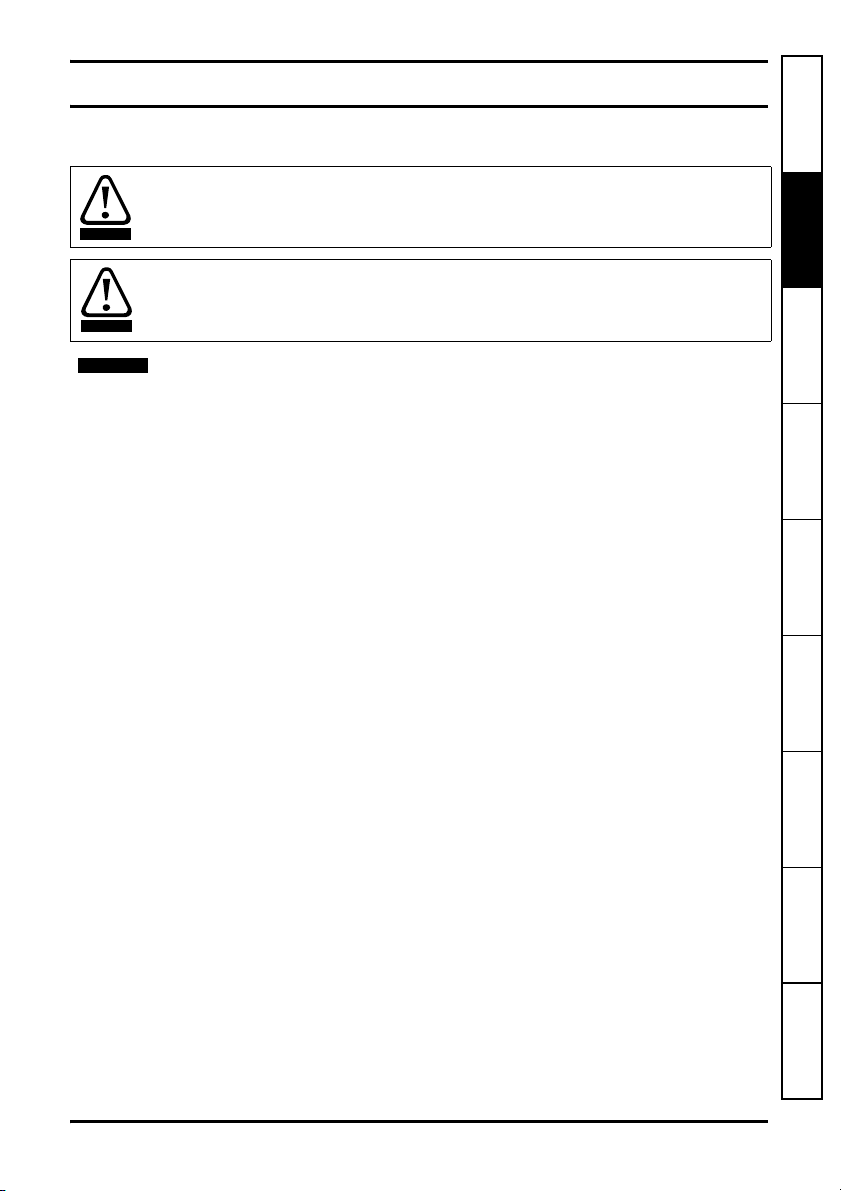
Figure 3-1 SM-Encoder Plus and SM-Encoder Output Plus
How to use this
guide
Safety information
Introduction
Solutions Module
Installing the
Getting started Parameters Diagnostics Terminal data Index
The SM-Encoder Plus and SM-Encoder Output Plus can be identified by:
1. The label located on the underside of the Solutions Module.
2. The colour coding across the front of the Solutions Module.
SM-Encoder Plus: Brown
SM-Encoder Output Plus: Dark Brown
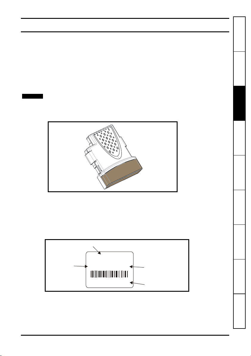
Figure 3-2 SM-Encoder Plus and SM-Encoder Output Plus label
olutions Module
name
Issue
number
SM-XXXXXXX
Issue: 0
Ser No : 3000005001
STDJ41
Customer
and date code
Serial number
3.2.1 Date code format
The date code is split into two sections: a letter followed by a number.
SM-Encoder Plus & SM-Encoder Output Plus User Guide 7
Issue: 4 www.controltechniques.com
The letter indicates the year, and the number indicates the week number (within the
year) in which the Solutions Module was built.
The letters go in alphabetical order, starting with A in 1990 (B in 1991, C in 1992 etc.).
Page 8
Example:
A date code of L35 would correspond to week 35 of year 2002.
3.3 Set-up parameters
All parameters associated to the SM-Encoder Plus or SM-Encoder Output Plus can be
found in either menu 15, 16, or 17. Each of menus 15, 16, and 17 refer to one of the
available slots into which the Solutions Module can be fitted. Slot 1 = Menu 15, Slot 2 =
Menu 16, Slot 3 = Menu 17.
NOTE
There are only two available slots for Unidrive SP size 0 and Digitax ST.
3.4 Compatible encoder types
The SM-Encoder Plus and SM-Encoder Output Plus are compatible with the following
encoders types:
Incremental encoders Ab, Fd, and Fr
This type of encoder gives incremental position and can only be used for control in
Closed Loop Vector and not Servo mode.
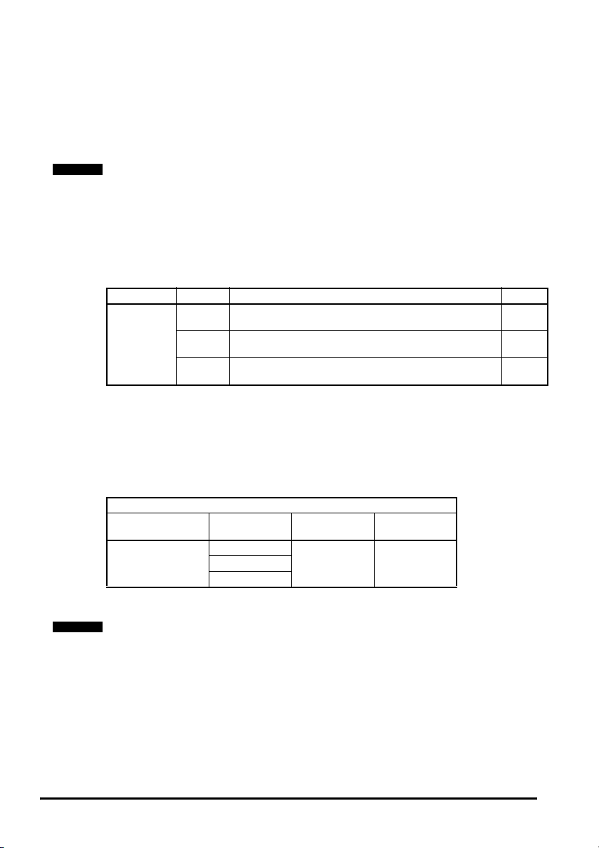
Type Encoder Description Pr x.15
Quadrature incremental encoder.
Ab
With or without marker pulse.
Incremental
Quadrature detection logic determines rotation from the phase relationship of the two
channels.
These encoders are available with a marker pulse, which identifies each individual
rotation of the disc, and is also used to reset the drive position parameter. The
incremental encoder can be used when operating in Closed Loop Vector mode, with the
optional marker pulse not being required for correct operation.
Incremental encoder with frequency and direction outputs.
Fd
With or without marker pulse.
Incremental encoder with forward and reverse outputs.
Fr
With or without marker pulse.
0
1
2
Limitations
Type Encoder Max Input
Ab
Incremental
Fr
Frequency
500kHz* 16,384Fd
Max no. of
Lines (LPR)
* Max input frequency = LPR x rpm / 60
NOTE
The maximum speed in rpm which an encoder connected to the SM-Encoder Plus or
SM-Encoder Output Plus can reach can be calculated from :
Max rpm = (60 x Max input frequency) / Encoder LPR
e.g. For a 4096 line encoder the maximum rpm would be:
(60 x 500 x 10
3
) / 4096 = 7324rpm
8 SM-Encoder Plus & SM-Encoder Output Plus User Guide
www.controltechniques.com Issue: 4
Page 9
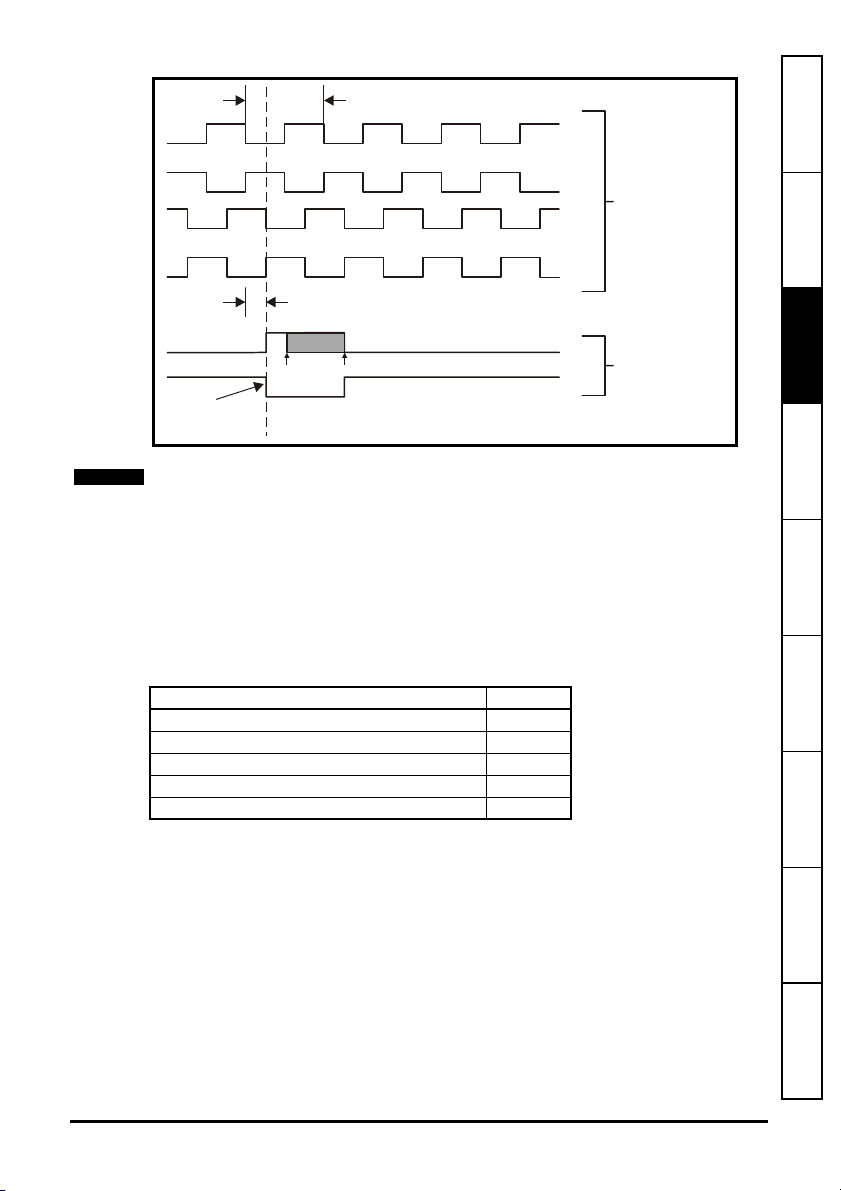
Figure 3-3 Encoder feedback signals
l
360 electrical (encoder)
°
90 separation of A and B
°
min max
Index
alignment
reference
A
/A
B
/B
Z
/Z
Incrementa
signals
Marker
signals
How to use this
guide
Safety information
Introduction
Solutions Module
Installing the
NOTE
Only encoders with lines per revolution that are a power of 2 can be used with the SMEncoder Plus and SM-Encoder Output Plus, e.g. 256, 512, 1024 etc.
The marker pulse duration must be between 45° to 360° electrical (encoder).
3.5 Simulated outputs (SM-Encoder Output Plus only)
The SM-Encoder Output Plus can provide simulated encoder output signals. The
source position is derived from either the encoder input on the module or from the drive
encoder input. The source encoder can be any incremental type or any sincos type of
encoder. If a sincos type is used as the source, the simulation output is derived from the
zero crossings of the sine waves and does not include interpolated information.
Mode x.28
Quadrature outputs 0
Frequency and direction outputs 1
Forward and reverse outputs 2
Quadrature outputs with marker lock 3
Frequency and direction outputs with marker lock 4 to 7
If a mode with marker lock is selected the incremental position is shifted when the first
input marker occurs so that with quadrature mode the marker is aligned with A high and
B high, and with frequency and direction mode the marker is aligned with F high.
The SM-Encoder Output Plus provides the ability to scale down the simulated encoder
output signals.
Getting started Parameters Diagnostics Terminal data Index
SM-Encoder Plus & SM-Encoder Output Plus User Guide 9
Issue: 4 www.controltechniques.com
Page 10
4 Installing the Solutions Module
Before installing or removing a Solutions Module in any drive, ensure the AC supply has
been disconnected for at least 10 minutes and refer to Chapter 2 Safety information on
WARNING
4.1 General Installation
page 5. If using a DC bus supply ensure this is fully discharged before working on any
drive or Solutions Module.
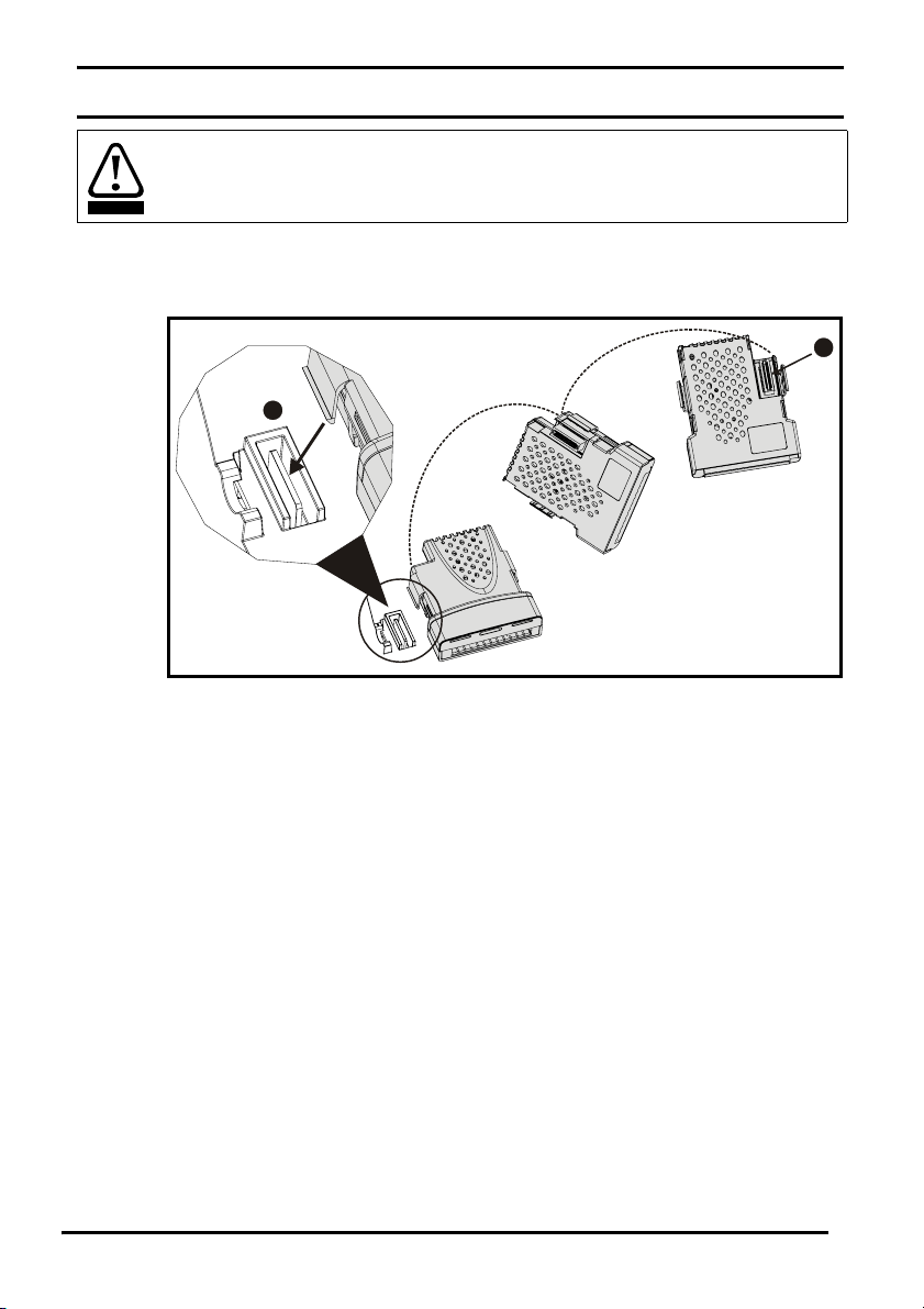
The installation of a Solutions Module is illustrated in Figure 4-1.
Figure 4-1 Fitting a Solutions Module
2
The Solutions Module connector is located on the underside of the module (1). Push
this into the Solutions Module slot located on the drive until it clicks into place (2). Note
that some drives require a protective tab to be removed from the Solutions Module slot.
For further information, refer to the appropriate drive manual.
1
10 SM-Encoder Plus & SM-Encoder Output Plus User Guide
www.controltechniques.com Issue: 4
Page 11
4.2 Terminal descriptions
r
4.2.1 SM-Encoder Plus
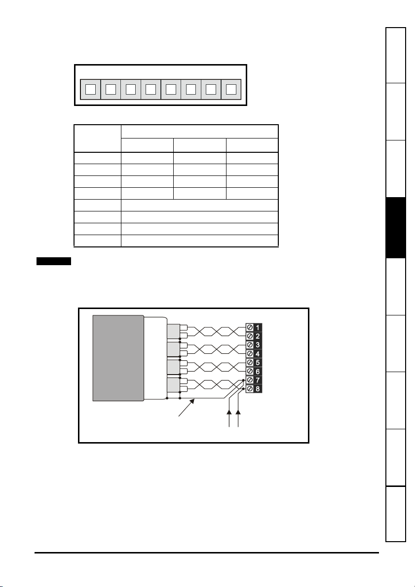
Figure 4-2 SM-Encoder Plus terminals
PL1
12345678
Table 4.1 SM-Encoder Plus terminal descriptions
Ter m En coder
Ab Fd Fr
1A F F
2A\ F\ F\
3B D R
4B\D\R\
5Z
6Z\
70V
8 External power supply decoupling
How to use this
guide
Safety information Introduction
Solutions Module
Installing the
NOTE
Terminal 8 should be used to join the external encoder power supply to the encoder as
shown in Figure 4-3. If the drive encoder supply is to be used for two encoders, the user
must ensure the total load does not exceed 300mA for 5V and 8V encoders and 200mA
for 15V encoders.
Figure 4-3 Encoder cable connections
Screen
connection
External encode
power supply
0V +V
Getting started Parameters Diagnostics Terminal data Index
SM-Encoder Plus & SM-Encoder Output Plus User Guide 11
Issue: 4 www.controltechniques.com
Page 12
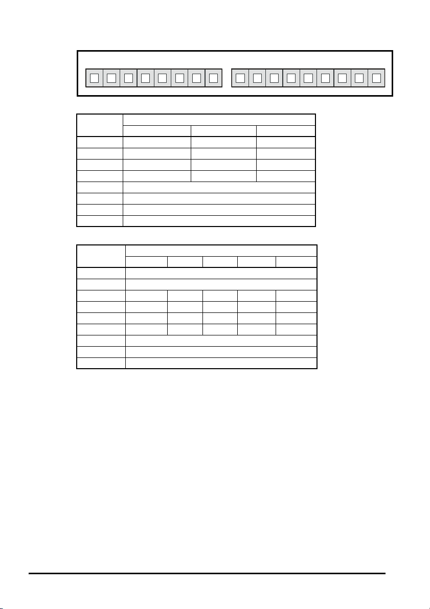
4.2.2 SM-Encoder Output Plus
Figure 4-4 SM-Encoder Output Plus terminals
PL1 PL2
12345678 12345678
Table 4.2 SM-Encoder Output Plus PL1 terminal descriptions
Term
1A F F
2A\ F\ F\
3B D R
4B\ D\ R\
5Z
6Z\
70V
8+V
Ab Fd Fr
Encoder inputs
Table 4.3 SM-Encoder Output Plus PL2 terminal descriptions
Term
10V
20V
3AFFAF
4A\F\F\A\F\
5BDRBD
6B\D\R\B\D\
70V
8Z
9Z\
Ab Fd Fr Ab.L Fd.L
Encoder outputs
9
4.3 Wiring, Shield connections
Shielding considerations are important for PWM drive installations due to the high
voltages and currents present in the output circuit with a very wide frequency spectrum,
typically from 0 to 20 MHz. Encoder inputs are liable to be disturbed if careful attention
is not given to managing the cable shields.
Encoder mounting methods
There are three methods for mounting an encoder onto a motor:
1. Galvanic isolation between encoder and motor
2. Galvanic isolation between encoder circuit and encoder body
3. No Isolation
4.3.1 Encoder with galvanic isolation from motor
When galvanically isolated the encoder device is mounted to the motor with isolation
fitted between the motor housing / shaft and encoder as shown in Figure 4-5.
12 SM-Encoder Plus & SM-Encoder Output Plus User Guide
www.controltechniques.com Issue: 4
Page 13
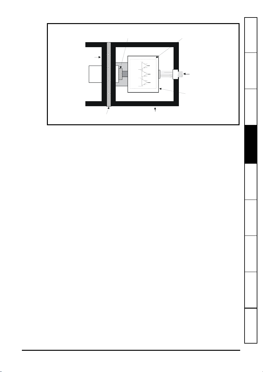
Figure 4-5 Galvanic Isolation from motor
Isolation
between motor shaft
and encoder
Encoder
Circuit
How to use this
guide
Motor
Housing
Motor
Shaft
Isolation
between motor housing
and encoder housing
+5V
+5V
+5V
0V
A
A
0V
B
B
0V
Z
Z
Encoder
Housing
Encoder
Connection
Encoder
Body
An example of this is the Unimotor where isolation from the motor is achieved by
inserting a plastic mounting plate between the motor housing and encoder housing and
a plastic insert fitted in the motor shaft for encoder mounting to the motor shaft. With this
preferred method of mounting noise current is prevented from passing from the motor
housing into the encoder housing, and hence into the encoder cable. The ground
connection of the cable shield is optional, this may be required to comply with safety
measures or to reduce radiated radio frequency emissions from either the drive or
encoder.
4.3.2 Encoder circuit with galvanic isolation from encoder body
In this case the encoder device is mounted directly on the motor housing with contact
being made between the motor housing/shaft and encoder. With this mounting method
the encoder internal circuits are exposed to electrical noise from the motor housing
through the stray capacitance, and they must be designed to withstand this situation.
However this arrangement still prevents large noise currents from flowing from the
motor body into the encoder cable. The ground connection of the cable shield is
optional, this may be required to comply with safety measures or to reduce radiated
radio frequency emissions from either the drive or encoder.
Safety information Introduction
Solutions Module
Getting started Parameters Diagnostics Terminal data Index
Installing the
SM-Encoder Plus & SM-Encoder Output Plus User Guide 13
Issue: 4 www.controltechniques.com
Page 14

Figure 4-6 Encoder galvanically isolated from encoder body
4.3.3 No isolation
As shown in Figure 4-7 the encoder 0V connection may be permanently connected to
the housing. This has the advantage that the encoder body can form a shield for its
internal circuits. However it permits noise current from the motor body to flow into the
encoder cable shield. A good quality shielded cable correctly terminated protects the
data against this noise current, but much more care is needed in ensuring correct cable
management than for the isolated cases.
Figure 4-7 No isolation
Motor
Housing
Motor
Shaft
No Isolation
between motor housing
and encoder housing
No Isolation
between motor shaft
and encoder
0V
+5V
0V
+5V
0V
+5V
Galvanic
Isolation
No Isolation
between motor shaft
and encoder
Encoder
Circuit
Stra y
Capacitance
A
A
B
B
Z
Z
Encoder
Housing
Encoder
Circuit
Encoder
Connection
Encoder
Body
Stra y
Motor
Housing
Motor
Shaft
No Isolation
between motor housing
and encoder housing
0V
+5V
0V
+5V
0V
+5V
Encoder
Housing
A
A
B
B
Z
Z
Encoder
Body
Capacitance
Encoder
Connection
0V
connected
to encoder
housing
14 SM-Encoder Plus & SM-Encoder Output Plus User Guide
www.controltechniques.com Issue: 4
Page 15

4.3.4 Cable requirements
p
All mounting methods:
• Shield connection at drive terminal to 0V
• Shield connection at encoder to 0V
• It is recommended that the shielded cable should be run in a continuous length to
the terminal, to avoid the injection of noise at intermediate pigtails and to maximise
the shielding benefit.
• The shield connections ("pigtails") to the drive and encoder should be kept as short
as possible
Mounting with no isolation:
• Shield connected to ground at both ends. The connection must be made by direct
fixing of the cable to the grounded metal parts, i.e. to the encoder body and the
drive grounding bracket, as illustrated in Figure 4.9. "Pigtails" must be avoided. The
outer sheath of the cable should be stripped back enough to allow for the ground
clamp to be fitted. The shield connection should not be broken. The ground clamps
should be located as close as possible to the drive and encoder.
• It is essential that the shielded cable should be run in a continuous length to the
terminal, to avoid the injection of noise at intermediate "pigtails" and to maximise the
shielding benefit.
In this case under no circumstances must the cable shield connection be omitted at
either end of the cable in this case, since the noise voltage may well be sufficient to
CAUT ION
WARNING
destroy the line driver and receiver chips in the encoder and the drive.
Cable shield ground connection
For all mounting methods, grounding of the feedback cable shield has added benefits. It
can protect the drive and encoder from induced fast electrical transients, and prevent
radiated radio-frequency emission. However it is essential that it be carried out in the
correct manner as explained above and shown in Figure 4-9.
Connecting the cable shield to ground at both ends carries the risk that an electrical fault
might cause excessive power current to flow in the cable shield and overheat the cable.
There must be an adequately rated safety ground connection between the motor/
encoder and the drive.
Recommended Cable
The recommended cable for feedback signals is a twisted pair, shielded with an overall
shield as shown below.
Figure 4-8 Feedback cable, twisted pair
Cable overall shield
How to use this
guide
Safety information Introduction
Solutions Module
Installing the
Getting started Parameters Diagnostics Terminal data Index
Twisted
pair
cable
Twisted
air shield
Cable
Using this type of cable also allows for the connection of the outer shield to ground and
the inner shields to 0V alone at both drive and encoder end, when required.
SM-Encoder Plus & SM-Encoder Output Plus User Guide 15
Issue: 4 www.controltechniques.com
Page 16

NOTE
Twi
on shield
Ensure that feedback cables are kept as far away as possible from power cables and
avoid parallel routing.
Figure 4-9 Feedback cable connections
sted
pair
shield
Shield
connection
to 0V
Shield
connection
to 0V
Twis ted
pair
shield
Cable
Connection
at drive
Cable
shield
Ground clamp
Cable
shield
Connection
at motor
16 SM-Encoder Plus & SM-Encoder Output Plus User Guide
www.controltechniques.com Issue: 4
Page 17

5 Getting started
5.1 Installation
The control circuits are isolated from the power circuits in the drive by basic insulation
only, as specified in IEC60664-1. The installer must ensure that the external control
WARNING
circuits are insulated from human contact by at least one layer of insulation rated for use
at the AC supply voltage.
If the control circuits are to be connected to other circuits classified as Safety Extra Low
Voltage (SELV) (e.g. to a personal computer) an additional isolating barrier must be
included in order to maintain the SELV classification.
Encoder connections
In order to ensure correct operation there are a number of checks which should be
carried out:
• Ensure the encoder is securely mounted to the motor as spurious operation can
result due to the encoder slipping whilst the motor is rotating.
• Ensure encoder connections to both the encoder and the Solutions Module
terminals are secured, intermittent connections can result in spurious operation or
the Solutions Module not detecting the feedback signals.
• Ensure screening recommendations as specified in Chapter 4.4 Wiring, Shield
connections on page 14 are followed to prevent noise being induced on the encoder
feedback signals. Noise induced on encoder feedback cables cannot only result in
spurious operation but in extreme cases can result in encoder failure and/or
damage to the Solutions Modules encoder input.
Encoder feedback and communications data is transmitted from an encoder as low
voltage analog or digital signals. Ensure that electrical noise from the drive or motor
does not adversely affect the encoder feedback. Ensure that the drive and motor are
connected as per the instructions given in the approriate drive manual, and that the
encoder feedback wiring and shielding recommendations are followed in section
4.3 Wiring, Shield connections on page 12.
How to use this
guide
Safety information Introduction
Solutions Module
Installing the
Getting started Parameters Diagnostics Terminal data Index
SM-Encoder Plus & SM-Encoder Output Plus User Guide 17
Issue: 4 www.controltechniques.com
Page 18

5.2 Incremental set-up
The following parameter set-up should be followed when operating with an Incremental Encoder
Incremental encoders, Ab, Fd and Fr
Action Detail
Ensure:
Before power-up
Power up drive
Error detection
Slot identification
Select Solutions
Module
Set-up encoder power
supply (SM-Encoder
Output Plus only)
Set-up encoder
parameters
Set-up encoder lines
per revolution
Initialisation
• Drive SECURE DISABLE/SAFE TORQUE OFF is not given (terminal 31)
• Run signal is not given
• Solutions Module is fitted in appropriate slot
• Feedback device is connected
Ensure:
• Drive displays ‘inh’
If the drive trips see Chapter 7 Diagnostics on page 35
Ensure:
• If no encoder is connected the encoder input on the drive then Pr 3.40 should be
set to 0 to disable the drive encoder input wire break detection (Enc2 trip).
Identify which Solutions Module slot and menu are being used
• Slot 1 – Menu 15
• Slot 2 – Menu 16
• Slot 3 – Menu 17
Enter:
• Speed feedback selector Pr 3.26
1: Slot 1
2: Slot 2
3: Slot 3
Enter:·
• Encoder power supply Pr x.13.
0: 5V, 1: 8V, 2: 15V
Enter:
• Encoder type Pr x.15
0 (Ab) 1 (Fd) 2 (Fr)
• Equivalent lines per revolution Pr x.10
Set according to encoder, see below for restrictions
Encoder Pr x.10 Equivalent lines per revolution
Ab Number of lines per revolution
Fd, Fr Number of lines per revolution / 2
Ensure:
Position feedback is initialised Pr x.45
18 SM-Encoder Plus & SM-Encoder Output Plus User Guide
www.controltechniques.com Issue: 4
Page 19

5.3 Simulated encoder output set-up
SM-Encoder Output Plus only
The following parameter set-up should be followed to obtain a simulated encoder
output.
How to use this
guide
Function Detail
Simulation
source
Simulation
ratio
Simulation
output mode
• Set the source of the simulated encoder output in Pr x.24.
x.05: The encoder input on the Solutions Module
3.29: The encoder input on the drive
• Set the required ratio between the source and output lines per revolution in
Pr x.25.
1.0000: ratio of 1
0.5000: ratio of 1/2
0.2500: ratio of 1/4
0.1250: ratio of 1/8
0.0625: ratio of 1/16
0.0312: ratio of 1/32
• Set the required encoder simulation mode in Pr x.28.
0: Ab – Quadrature outputs
1: Fd – Frequency and direction outputs
2: Fr – Forward and reverse outputs
3: Ab.L – Quadrature outputs with marker lock
4: Fd.L – Frequency and direction outputs with marker lock
5.4 Freeze function
The SM-Encoder Plus and SM-Encoder Output Plus have a freeze function, but do not
have freeze inputs. The freeze function can be activated using either the SMApplications or SM-Universal Encoder Plus. When a freeze signal is applied, the freeze
flag (Pr x.39) is set to "ON". When activated, the non-marker position data (Pr x.29 and
Pr x.30) is transferred into Pr x.35 and Pr x.36.
The freeze flag does not reset itself. Before carrying out consecutive freeze functions,
the SM-Encoder Plus or SM-Encoder Output Plus freeze flag must be cleared by the
user (Pr x.39 = "OFF").
NOTE
If a SM-Universal Encoder Plus is used as a freeze input, it must be set to freeze the
drive position by setting Pr x.40 to “On”. Also, before consecutive freeze operations can
be performed in the SM-Encoder Plus or SM-Encoder Output Plus, the SM-Universal
Encoder Plus freeze flag (Pr x.39) must be cleared together with the SM-Encoder Plus
or SM-Encoder Output Plus freeze flag (Pr x.39).
E.g. If slot 3 has a SM-Universal Encoder Plus fitted and slot 2 has an SM-Encoder Plus
fitted, Pr 16.39 and Pr 17.39 need to be set to “OFF” before another freeze function can
be performed on the SM-Encoder Plus or SM-Encoder Output Plus.
Safety information Introduction
Solutions Module
Getting started Parameters Diagnostics Terminal data Index
Installing the
5.5 Termination resistors
By default the termination resistors on the encoder inputs are enabled with the
exception of the marker pulse inputs which are disabled. The termination resistors can
be can be configured as shown below using encoder termination Pr x.16.
Ter mi nal Encoder Input Pr x.16=0 Pr x.16=1 Pr x.16=2
1, 2 A, A\ Disabled Enabled Enabled
3, 4 B, B\ Disabled Enabled Enabled
5, 6 Z, Z\ Disabled Disabled Enabled
The termination resistance when connected (A, A\) = 120Ω total.
SM-Encoder Plus & SM-Encoder Output Plus User Guide 19
Issue: 4 www.controltechniques.com
Page 20

6 Parameters
6.1 Introduction
The parameters listed in this chapter are used for programming and monitoring the SMEncoder Plus and SM-Encoder Output Plus
The SM-Encoder Plus and SM-Encoder Output Plus are classed as dumb modules as
they do not have their own processors, and as a result all parameters are updated by
the drive processor.
The SM-Encoder Plus and SM-Encoder Output Plus parameters are read/written by the
drive background task or at the combined update time for time critical parameters. The
combined update time depends on the number and type of dumb modules fitted to the
drive. For each dumb module the update rate of these parameters is specified as either
4 or 8ms. The combined update time is the total of the update times for all dumb
modules fitted. (E.g. if two modules with 4ms and 8ms update times are fitted to the
drive, then the combined update time for the time critical parameters of each module will
be 12ms.)
Dumb module Update time
SM-I/O Plus 8ms
SM-Encoder Plus 4ms
SM-Encoder Output Plus 4ms
SM-Resolver 4ms
Some functions with the SM-Encoder Plus or SM-Encoder Output Plus modules do not
function correctly if the update time is too long. The input frequency should not exceed
500kHz, but in addition the number of encoder counts seen over one sample period
should not exceed 32768. Provided the frequency is within the 500kHz limit, the
maximum count cannot be exceeded with Fd and Fr encoders with any sample time, or
with Ab encoders if the sample time is 16ms or less. If the sample time is 20ms then the
maximum allowed frequency with Ab encoders is 409.6kHz.
Position/speed feedback update rate
If the module is selected for motor control position feedback then the position and speed
parameters are updated as defined with each parameter, but are available within the
drive at a faster rate as shown below.
Control position Current controller sample rate
Control speed 250us
Position controller position (menu 13) 4ms
Position for SM-Applications module, etc. 250us
If the module is not selected for motor control position feedback the position and speed
are updated as defined with the appropriate parameters.
NOTE
The same parameter structure is available in menu 15, 16 and 17 referring to slots 1, 2
and 3.
20 SM-Encoder Plus & SM-Encoder Output Plus User Guide
www.controltechniques.com Issue: 4
Page 21

WARNING
Before attempting to adjust any parameters, refer to Chapter 2 Safety information on
page 5.
How to use this
guide
Table 6.1 Key to parameter coding
Coding Attribute
RW Read/write: can be written by the user
RO Read only: can only be read by the user
Bit 1 bit parameter
Bi Bipolar parameter
Uni Unipolar parameter
Txt Text: the parameter uses text strings instead of numbers.
Filtered: some parameters which can have rapidly changing values are
FI
filtered when displayed on the drive keypad for easy viewing.
DE Destination: indicates that this parameter can be a destination parameter.
NC Not cloned: not transferred to or from smart cards during cloning.
PT Protected: cannot be used as a destination.
User save: saved in drive EEPROM when the user initiates a parameter
US
save.
Power-down save: automatically saved in drive EEPROM at power-down
PS
when the under volts (UV) trip occurs.
Safety information Introduction
Solutions Module
Getting started
Parameters Diagnostics Terminal data Index
Installing the
SM-Encoder Plus & SM-Encoder Output Plus User Guide 21
Issue: 4 www.controltechniques.com
Page 22

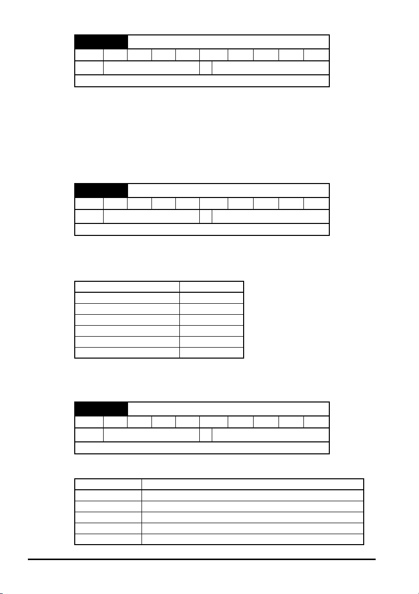
6.2 Single line descriptions
Ú) Default(Ö)
Parameter
x.01 Solutions Module ID 0 to 599 104 RO Uni PT US
x.03 Speed feedback ±40,000.0 rpm
x.04 Revolution counter 0 to 65,535 revolutions
x.05 Position
Marker position reset
x.07
disable
x.08 Marker flag OFF (0) or On (1) OFF (0) RW Bit NC
Equivalent lines per
x.10
revolution
x.13* Encoder supply voltage
x.15 Encoder type Ab (0), Fd (1), Fr (2) Ab (0) RW Uni US
x.16 Encoder termination 0 to 2 1 RW Bit US
x.19 Feedback filter 0 to 5 (0 to 16 ms) 0 RW Uni US
x.24* Encoder simulation source Pr 0.00 to Pr 21.51 0.00 RW Uni PT US
Encoder simulation ratio
x.25*
numerator
x.28* Encoder simulation mode
Non-marker reset
x.29
revolution counter
x.30 Non-marker reset position
x.32 Marker revolution counter 0 to 65,535 revolutions
x.33 Marker position
x.35 Freeze revolution counter 0 to 65,535 revolutions
x.36 Freeze position
x.39 Freeze flag OFF (0) or On (1) OFF (0) RW Bit NC
Position feedback
x.45
initialised
x.49 Lock position feedback OFF (0) or On (1)
Solutions Module error
x.50
status
Range(
OL CL OL VT SV
RO Bi FI NC PT
0 to 65,535 (1/2
OFF (0) or On (1) OFF (0) RW Bit US
0.0000 to 3.0000 0.2500 RW Uni US
3: Ab with marker lock
4 to 7: Fd with marker lock
0 to 65,535 revolutions
0 to 65,535 (1/2
0 to 65,535 (1/2
0 to 65,535 (1/2
OFF (0) or On (1)
16
0: 5V
1: 8V
2: 15V
0: Ab
1: Fd
2: Fr
0 to 255
ths of a
16
ths of a
16
ths of a
16
ths of a
0RWUni US
0RWUni US
revolution)
0 to 50,000 4,096 RW Uni US
revolution)
revolution)
revolution)
RO Uni FI NC PT
RO Uni FI NC PT
RO Uni NC PT
RO Uni NC PT
RO Uni NC PT
RO Uni NC PT
RO Uni NC PT
RO Uni NC PT
RO Bit NC PT
RW Bit
RO Uni NC PT
Typ e
RW Read / Write RO Read only Uni Unipolar Bi Bi-polar
Bit Bit parameter Txt Text string FI Filtered DE Destination
NC Not cloned RA Rating dependent PT Protected US User save
PS Power down save
NOTE
*Pr x.13, Pr x.24, Pr x.25 and Pr x.28 are only used when operating with a SM-Encoder
Output Plus module. These parameters are not used when operating with a SM-Encoder
Plus module
22 SM-Encoder Plus & SM-Encoder Output Plus User Guide
www.controltechniques.com Issue: 4
Page 23

How to use this
guide
Safety information Introduction
Solutions Module
Installing the
Getting started
SM-Encoder Plus & SM-Encoder Output Plus User Guide 23
Issue: 4 www.controltechniques.com
Parameters Diagnostics Terminal data Index
Page 24

Figure 6-1 SM-Encoder Plus logic diagram
Term Encoder
connections
1A
PL1
2A\
3B
4B\
5Z
6Z\
70V
8 Not used
x.10
x.16
x.15
Equivalent
lines per
revolution
Encoder
termination
Encoder
type
Position
feedback
initialised
x.45
Non marker position information
Revolution
Position
counter
x.29 x.30
Marker position information
Revolution
counter
Position
x.32 x.33
+
_
Freeze input
SM-Applications
SM-Universal
Encoder Plus
Freeze
flag
x.39
Marker
input
x.08
Marker
flag
Freeze positional
information
Freeze
x.35
revolution
counter
Freeze
x.36
position
x.07
Marker
position
disable
24 SM-Encoder Plus & SM-Encoder Output Plus User Guide
www.controltechniques.com Issue: 4
Page 25

How to use this
guide
Safety information Introduction
Revolution
Position
counter
x.04 x.05
Positional information
x.49
Lock position
feedback
Feedback
filter
x.19
Speed
x.03
Key
Input
terminals
Output
terminals
The parameters are all shown at their default settings
0.XX
0.XX
Read-write (RW)
parameter
Read-only (RO)
parameter
Solutions Module
Getting started
Parameters Diagnostics Terminal data Index
Installing the
SM-Encoder Plus & SM-Encoder Output Plus User Guide 25
Issue: 4 www.controltechniques.com
Page 26

Figure 6-2 SM-Encoder Output Plus logic diagram
_
Position
feedback
initialised
x.45
Marker
input
Freeze positional
information
Freeze
revolution
x.35
counter
Freeze
x.36
position
PL1
Solutions
Module
terminal
block
Freeze input
SM-Applications
SM-Universal
Encoder Plus
Term Enc oder
connections
1 A
2 A\
3 B
4 B\
5 Z
6 Z\
7 0V
8 +V
x.13
Encoder supply
voltage
x.39
Freeze
flag
x.10
x.16
x.15
x.15
Equivalent
lines per
revolution
Encoder
termination
Encoder
type
Non marker position information
Revolution
Position
counter
x.29 x.30
Marker position information
Revolution
Position
counter
x.32 x.33
x.08
Marker
flag
x.07
Marker
position
disable
+
Encoder
simulation
mode
Fd
Ab.L
Fd.L
Module encoder
port
Drive encoder
port
Position
x.05
3.29
Drive encoder
position
Encoder
simulation
source
Encoder
simulation
ratio numerator
26 SM-Encoder Plus & SM-Encoder Output Plus User Guide
www.controltechniques.com Issue: 4
Ab
Fr
Page 27

How to use this
guide
Safety information Introduction
Revolution
counter
x.04 x.05
Positional information
Ab Fd
A
A\
B
B\
F\
D
D\
F
Position
x.49
Lock position
feedback
Fr Ab.L
0V
0V
F
F\
R\
R\
0V
Z
Z\
Feedback
filter
x.19
A
A\
B
B\
Speed
x.03
The parameters are all shown at their default settings
Fd.L PL2 term
1
F
F\
D
D\
2
3
4
5
6
7
8
9
Input
terminals
Output
terminals
Key
0.XX
0.XX
Read-write (RW)
parameter
Read-only (RO)
parameter
Solutions
Module
terminal
block
PL2
Solutions Module
Getting started
Parameters Diagnostics Terminal data Index
Installing the
SM-Encoder Plus & SM-Encoder Output Plus User Guide 27
Issue: 4 www.controltechniques.com
Page 28

6.3 Parameter descriptions
x.01 Solutions Module ID code
RO Uni PT US
Ú
Update rate: Write on power-up
The menu for the relevant slot appears for the new Solutions Module category with the
default parameter values for the new category. When no Solutions Module is fitted in the
relevant slot this parameter is zero. When a Solutions Module is fitted this parameter
displays the identification code as shown below.
Solutions
Module ID
0 No module fitted
101 SM-Resolver
104 SM-Encoder Plus and SM-Encoder Output Plus
201 SM-I/O Plus
203 SM-I/O Timer
204 SM-I/O PELV
205 SM-I/O 24V Protected
206 SM-I/O 120V
207 SM-I/O Lite
208 SM-I/O 32
301 SM-Applications
302 SM-Applications Lite
303 SM-EZMotion
304 SM-Applications Plus
305 SM-Applications Lite V2
401 SM-LON
403 SM-PROFIBUS-DP
404 SM-INTERBUS
406 SM-CAN
407 SM-DeviceNet
408 SM-CANopen
409 SM-SERCOS
410 SM-Ethernet
501 SM-SLM SLM
0 to 599
Ö
Module Category
104
Feedback102 SM-Universal Encoder Plus
Automation
(I/O Expansion)
Automation
(Applications)
Fieldbus
The new parameters values are not stored in EEPROM until the user performs a
parameter save. When parameters are saved by the user in the drive EEPROM the
option code of the currently fitted Solutions Module is saved in EEPROM. If the drive is
subsequently powered-up with a different Solutions Module fitted, or no Solutions
Module fitted where one was previously fitted, the drive gives a SLx.dF or SLx.nF trip.
28 SM-Encoder Plus & SM-Encoder Output Plus User Guide
www.controltechniques.com Issue: 4
Page 29

x.03 Speed feedback
RO Bi FI NC PT
Ú
Update rate: 4ms x number of dumb modules
Provided the set-up parameters for the position feedback are correct this parameter
shows the speed in rpm.
x.04 Revolution counter
RO Uni FI NC PT
Ú
Update rate: 4ms x number of dumb modules
±40,000.0 rpm
0 to 65,535 revolutions
Ö
Ö
How to use this
guide
Safety information Introduction
x.05 Position
RO Uni FI NC PT
Ú
Update rate: 4ms x number of dumb modules
Pr x.04 and Pr x.05 give the position with a resolution of 1/2
bit number as shown below.
31 16 15 0
Revolutions Position
Provided the set-up parameters are correct, the position is always converted to units of
1/2
the resolution of the feedback device. For example if 10 bit resolution is selected the
resolver produces 4,096 counts per revolution, and so the position is represented by the
bits in the shaded area only.
31 16 15 4 3 0
Revolutions
When the feedback device rotates by more than one revolution, the revolutions in Pr
x.04 increment or decrement in the form of a sixteen bit roll-over counter.
RW Bit US
Ú
Update rate: Background read
0 to 65,535 (1/216ths
revolutions)
16
ths of a revolution, but some parts of the value may not be relevant depending on
Position
x.07 Marker position reset disable
OFF (0) or On (1)
Ö
Ö
OFF (0)
16
ths of a revolution as a 32
Solutions Module
Getting started
Parameters Diagnostics Terminal data Index
Installing the
SM-Encoder Plus & SM-Encoder Output Plus User Guide 29
Issue: 4 www.controltechniques.com
Page 30

x.08 Marker flag
RW Bit NC
Ú
Update rate: 4ms x number of dumb modules
An incremental digital encoder may have a marker channel and when this channel
becomes active (rising edge in the forward direction and falling edge in reverse) it may
be used to reset the encoder position and set the marker flag (Pr x.07 = 0), or just to set
the marker flag (Pr x.07 = 1). When the position is reset by the marker, Pr x.05 is reset
to zero.
The marker flag is set each time the marker input becomes active, but it is not reset by
the drive, and so this must be done by the user.
RW Uni US
Ú
Update rate: Background read (only has any effect when the drive is
disabled)
When Ab, Fd, or Fr signals are used the equivalent number of encoder lines per
revolution must be set-up correctly in Pr x.10 to give the correct speed and position
feedback. The equivalent number of encoder lines per revolution (ELPR) is defined as
follows:
Although Pr x.10 can be set to any value from 0 to 50,000, there are restrictions on the
values actually used as follows:
If Pr x.10 < 2, ELPR = 2. If Pr x.10 > 16,384, ELPR = 16,384. Otherwise, Pr x.10 is
rounded down to the nearest value that is a power of 2, e.g. if 5,000 is set in Pr x.10, the
drive actually uses 4,096.
OFF (0) or On (1)
x.10 Equivalent lines per revolution
0 to 50,000
Position feedback device ELPR
Ab number of lines per revolution
Fd, Fr number of lines per revolution / 2
Ö
Ö
OFF (0)
4,096
x.13 Encoder supply voltage
RW Uni US
Ú
Update rate: Background read
SM-Encoder Output Plus only
The encoder supply voltage for the SM-Encoder Output Plus module is defined by this
parameter as 0(5V), 1(8V), or 2(15V).
0 to 2
Ö
0
30 SM-Encoder Plus & SM-Encoder Output Plus User Guide
www.controltechniques.com Issue: 4
Page 31

x.15 Encoder type
RW Uni US
Ú
Ab (0), Fd (1), Fr (2)
Ö
Ab (0)
Update rate: 4ms x number of dumb modules
The following encoders can be connected to the SM-Encoder Plus.
0, Ab: Quadrature incremental encoder, with or without marker pulse
1, Fd: Incremental encoder with frequency and direction outputs, with or without marker
pulse
2, Fr: Incremental encoder with forward and reverse outputs, with or without marker
pulse
x.16 Encoder termination
RW Txt US
Ú
0 to 2
Ö
1
Update rate: Background read
The terminations may be enabled/disabled by this parameter as follows:
Encoder input x.16=0 x.16=1 x.16=2
A-A\ Disabled Enabled Enabled
B-B\ Disabled Enabled Enabled
Z-Z\ Disabled Disabled Enabled
x.19 Feedback filter
RW Uni US
Ú
0 to 5 (0 to 16 ms)
Ö
0
Update rate: Background read
A sliding window filter may be applied to the feedback. This is particularly useful in
applications where the feedback is used to give speed feedback for the speed controller
and where the load includes a high inertia, and so the speed controller gains are very
high. Under these conditions, without a filter on the feedback, it is possible for the speed
loop output to change constantly from one current limit to the other and lock the integral
term of the speed controller. The filter is not active if the parameter value is 0 or 1ms,
but operates over the defined window for parameter values of 2, 4, 8 and 16ms.
Value in Pr x.19 Filter window
0Not active
1Not active
22ms
44ms
88ms
16 16ms
How to use this
guide
Safety information Introduction
Solutions Module
Installing the
Getting started
Parameters Diagnostics Terminal data Index
SM-Encoder Plus & SM-Encoder Output Plus User Guide 31
Issue: 4 www.controltechniques.com
Page 32
x.24 Encoder simulation source
RO Uni PT US
Ú
Update rate: Read on reset
SM-Encoder Output Plus only
The encoder simulation system provides an encoder output with minimal delay from
either the drive encoder (Pr x.24 = 3.29) or the encoder connected to this option module
(Pr x.24 equal to any other value). The drive encoder can be an incremental encoder
(Ab, Fd, Fr, Ab.Servo, Fd.Servo, Fr.Servo) or it can be a SINCOS encoder (SC,
SC.Hiper, SC.EnDat or SC.SSI). If any other encoder types are selected the output is
undefined. If a SinCos type encoder is being used the encoder simulation is derived
from the sine waves and does not include interpolation information.
x.25 Encoder simulation ratio numerator
RO Uni PT US
Ú
Update rate: Background read
SM-Encoder Output Plus only
The ratio between the change of encoder position and the change of encoder simulation
output position is defined by Pr x.25. The table below shows the possible ratios.
For example, if the source encoder has a resolution of 4096 lines per revolution and
Pr x.25 set to 0.2500 (a ratio of ¼), the output resolution will be 1024 lines per
revolution.
0.00 to 21.51
0.0000 to 3.0000
Pr x.25 Ratio
0.0000 to 0.0312 1/32
0.0313 to 0.0625 1/16
0.0626 to 0.1250 1/8
0.1251 to 0.2500 1/4
0.2501 to 0.5000 1/2
0.5001 to 3.0000 1
Ö
Ö
0.00
0.2500
x.28 Encoder simulation mode
RO Uni US
Ú
Update rate: Background read
SM-Encoder Output Plus only
Pr x.28 selects the format of the encoder simulation output as shown in the table below.
Pr x.28 Mode
0 Ab Quadrature outputs
1 Fd Frequency and direction outputs
2 Fr Forward and reverse outputs
3 Ab.L Quadrature outputs with marker lock
4 to 7 Fd.L Frequency and direction outputs with marker lock
0 to 7
Ö
0
32 SM-Encoder Plus & SM-Encoder Output Plus User Guide
www.controltechniques.com Issue: 4
Page 33

The output marker pulse is derived directly from the encoder simulation input source
marker pulse. The width of the marker pulse is not adjusted with the encoder simulation
ratio, but remains the same width as the input marker pulse. If a mode without marker
lock is selected then the relationship between the marker pulse position and the
incremental signals is undefined. If a mode with marker lock is selected the incremental
position is shifted when the first input marker pulse occurs so that with Ab mode the
marker pulse is aligned with A high and B high, and with Fd mode the marker pulse is
aligned with F high. Marker lock is required when the system that is receiving the
encoder simulation signals requires a defined relationship between the marker pulse
and the incremental signals. Marker lock should not be used if the drive encoder
equivalent lines per revolution (ELPR) in Pr 3.34, is not a power of 2 or the ELPR of the
encoder simulation output is less than 1 after the divide ratio has been applied.
x.29 Non-marker reset revolution counter
RO Uni NC PT
0 to 65,535 revolutions
Ú
Update rate: 4ms x number of dumb modules
x.30 Non-marker reset position
RO Uni NC PT
0 to 65,535 (1/216ths of a
Ú
Update rate: 4ms x number of dumb modules
This position is taken from the position feedback device and is not affected by the
marker or the freeze inputs.
revolution)
Ö
Ö
How to use this
guide
Safety information Introduction
Solutions Module
Installing the
Getting started
x.32 Marker revolution counter
RO Uni NC PT
0 to 65,535 revolutions
Ú
Update rate: 4ms x number of dumb modules
x.33 Marker position
RO Uni NC PT
0 to 65,535 (1/216ths of a
Ú
Update rate: 4ms x number of dumb modules
Each time the marker becomes active, the non-marker position values (Pr x.29 and Pr
x.30) are sampled and stored in Pr x.32 and Pr x.33.
x.35 Freeze revolution counter
RO Uni NC PT
Ú
Update rate: 4ms x number of dumb modules
SM-Encoder Plus & SM-Encoder Output Plus User Guide 33
Issue: 4 www.controltechniques.com
revolution)
0 to 65535 revolutions
Ö
Ö
Ö
Parameters Diagnostics Terminal data Index
Page 34

x.36 Freeze position
RO Uni NC PT
0 to 65535 (1/216ths of a
Ú
Update rate: 4ms x number of dumb modules
x.39 Freeze flag
RW Bit NC
Ú
Update rate: 4ms x number of dumb modules
The SM-Encoder Plus and SM-Encoder Output Plus do not have their own freeze
inputs, therefore the freeze inputs must come from a SM-Applications or SM-Universal
Encoder Plus. The freeze data is processed every 4ms x number of dumb modules
fitted. If a freeze has occurred and the freeze flag (Pr x.39) is zero, the position data is
stored in Pr x.35 and Pr x.36 and the freeze flag is set. The freeze flag must be reset by
the user before the next freeze event is stored.
x.45 Position feedback initialised
RO Bit NC PT
Ú
Update rate: 4ms x number of dumb modules
At power-up Pr x.45 is initially OFF (0), but is set to On (1) when the Solutions Module
can provide position feedback. Pr x.45 then remains at On (1) whilst the drive is
powered-up.
revolution)
OFF (0) or On (1)
OFF (0) or On (1)
Ö
Ö
Ö
OFF (0)
x.49 Lock position feedback
RW Bit
Ú
Update rate: Background write
If Pr x.49 is set to one, Pr x.04 and Pr x.05 are not updated. If this parameter is zero,
Pr x.04 and Pr x.05 are updated normally.
RO Uni NC PT
Ú
The error status is provided so that the only one option error trip is required for each
Solutions Module slot. If an error occurs, the reason for the error is written to this
parameter and the drive may produce a ‘SLX.Er’ trip, where X is the slot number. A
value of zero indicates the Solutions Module has not detected an error, a non-zero value
indicates that an error has been detected. (See Table 7.1 Trip codes on page 36 for the
meaning of the values in this parameter.) When the drive is reset, this parameter is
cleared.
OFF (0) or On (1)
x.50 Solutions Module error status
0 to 255
Ö
Ö
34 SM-Encoder Plus & SM-Encoder Output Plus User Guide
www.controltechniques.com Issue: 4
Page 35
7 Diagnostics
U
D
)
If the drive trips, the output is disabled so that the drive stops controlling the motor. The
lower display indicates that a trip has occurred and the upper display shows the trip.
Trips are listed alphabetically in Table 7.1 based on the trip indication shown on the
drive display. Refer to Figure 7-1.
If a display is not used, the drive LED Status indicator will flash if the drive has tripped.
Refer to Figure 7-2.
The trip indication can be read in Pr 10.20 providing a trip number.
7.1 Displaying the trip history
The drive retains a log of the last 10 trips that have occurred in Pr 10.20 to Pr 10.29 and
the corresponding multi-module drive module number (Pr 6.49 = 0) or the trip time
(Pr 6.49 = 1) for each trip in Pr 10.41 to Pr 10.51. The time of the trip is recorded from
the powered-up clock (if Pr 6.28 = 0) or from the run time clock (if Pr 6.28 = 1).
Pr 10.20 is the most recent trip, or the current trip if the drive is in a trip condition (with
the module number or trip time stored in Pr 10.41 and stored in Pr 10.51). Each time a
new trip occurs, all the parameters move down one, such that the current trip (and time)
is stored in Pr 10.20 (and Pr 10.41 to Pr 10.42) and the oldest trip (and time) is lost out
of the bottom of the log.
If any parameter between Pr 10.20 and Pr 10.29 inclusive is read by serial
communications, then the trip number in Table 7.1 Trip codes on page 36 is the value
transmitted.
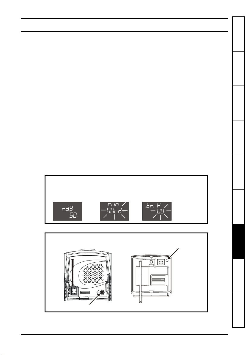
Figure 7-1 Keypad status modes
Status Mode
How to use this
guide
Safety information Introduction
Solutions Module
Installing the
Getting started Parameters
Healthy Status
Figure 7-2 Location of the status LED
Unidrive SP
(sizes 1 to 6)
LED
Non flashing: Normal status
Flashing: Trip status
SM-Encoder Plus & SM-Encoder Output Plus User Guide 35
Issue: 4 www.controltechniques.com
Trip StatusAlarm Status
Drive status
= tripped
Trip type (U
= undervolts)
Unidrive SP (size 0
Digitax ST
LE
Diagnostics Terminal data Index
Page 36

Any trip can be initiated by writing the relevant trip number to Pr 10.38. If any trips
shown as user trips are initiated the trip string is "txxx", where xxx is the trip number.
Trips can be reset after 1.0s if the cause of the trip has been rectified.
A full list of drive trips can be found in the appropriate drive manual.
Table 7.1 Trip codes
Trip Diagnosis
C.Optn
Enc1 Drive encoder trip: Encoder power supply overload
Enc2 Drive encoder trip: Wire break (Drive encoder terminals 1 & 2, 3 & 4, 5 & 6)
PS.24V 24V internal power supply overload
SLX.dF Solutions Module slot X trip: Solutions Module type fitted in slot X changed
204,209,
SLX.Er
SMARTCARD trip: Solutions Modules fitted are different between source drive
and destination drive
Ensure correct Solutions Modules are fitted
Ensure Solutions Modules are in the same Solutions Module slot
180
Press the red reset button
Check encoder power supply wiring and encoder current requirement
189
Maximum current = 200mA @ 15V or 300mA @ 8V and 5V
Check cable continuityCheck wiring of feedback signals is correct
Check encoder power supply is set correctly
Replace feedback device
190
If wire break detection on the main drive encoder input is not required, set Pr 3.40= 0
to disable the Enc2 trip
The total user load of the drive and Solutions Modules has exceeded the internal 24V
power supply limit.
The user load consists of the drive’s digital outputs plus the SM-I/O Plus digital
outputs, or the drive’s main encoder supply plus the SM-Universal Encoder Plus and
9
SM-Encoder Output Plus encoder supplies.
• Reduce load and reset
• Provide an external 24V >50W power supply
• Remove any Solutions Modules and reset
Save parameters and reset
214
Solutions Module slot X trip: Error detected with Solutions Module, where X is
the slot number
202
207
212
Pr x.50 Fault description
0 No errors
1 Power supply overloaded
When the drive is reset this parameter is cleared for the relevant Solutions Module
SLX.HF Solutions Module slot X trip: Solutions Module X hardware fault
200,205,
Ensure Solutions Module is fitted correctly
210
Return Solutions Module to supplier
36 SM-Encoder Plus & SM-Encoder Output Plus User Guide
www.controltechniques.com Issue: 4
Page 37

Trip Diagnosis
SLX.nF Solutions Module slot X trip: Solutions Module has been removed
203,208,
Ensure Solutions Module is fitted correctly
Replace Solutions Module
213
Save parameters and reset drive
SLX.tO Solutions Module slot X trip: Solutions Module watchdog time-out
203,208,
SL.rtd
Press reset.
211
If the trip persists, contact the supplier of the drive.
Solutions Module trip: Drive mode has changed and Solutions Module
parameter routing is now incorrect
Press reset.
215
If the trip persists, contact the supplier of the drive.
How to use this
guide
Safety information Introduction
Solutions Module
Installing the
Getting started Parameters
SM-Encoder Plus & SM-Encoder Output Plus User Guide 37
Issue: 4 www.controltechniques.com
Diagnostics Terminal data Index
Page 38

8Terminal data
8.1 Encoder inputs (PL1)
Ab, Fd, and Fr encoders
Channel A, Frequency or Forward inputs
1
Channel A\, Frequency\ or Forward\ inputs
2
Channel B, Direction or Reverse inputs
3
Channel B\, Direction\ or Reverse\ inputs
4
Marker pulse channel Z
5
Marker pulse channel Z\
6
Type EIA 485 differential receivers
Maximum frequency 500kHz
Line loading <2 unit loads
Line termination components
Working common mode range +12Vdc to –7Vdc
Absolute maximum applied voltage relative to
0V
Absolute maximum applied differential voltage ±25V
0V Common
7
8.1.1 SM-Encoder Plus
120
±25V
Ω
External power supply decoupling
8
Maximum voltage ±50Vdc
8.1.2 SM-Encoder Output Plus
Encoder supply voltage
8
Supply voltage 5V, 8V or 15V
Maximum output current
300mA for 5V and 8V
200mA for 15V
The encoder supply voltage is controlled by Pr x.13. The default for this parameter is 5V
(0) but this can be set to 8V (1) or 15V (2). Setting the encoder voltage supply too high
for the encoder could result in damage to the feedback device.
The termination resistors should be disabled (Pr x.16 = 0) if the outputs from the
encoder are higher than 5V.
38 SM-Encoder Plus & SM-Encoder Output Plus User Guide
www.controltechniques.com Issue: 4
Page 39

8.2 Encoder Outputs (PL2)
SM-Encoder Output Plus only
Simulated Ab, Fd and Fr encoder output
0V Common
1
0V Common
2
Channel A, Frequency or Forward
3
Channel A\, Frequency\ or Forward\
4
Channel B, Direction or Reverse
5
Channel B\, Direction\ or Reverse\
6
Marker pulse Z
8
Marker pulse Z\
9
Type EIA 485 differential receivers
Maximum frequency 500kHz
Line loading 1 unit load
Line termination components
Working common mode range +12V to –7V
Absolute maximum applied voltage relative to 0V ±25V
Absolute maximum applied differential voltage ±25V
120
Ω
How to use this
guide
Safety information Introduction
Solutions Module
Installing the
Getting started Parameters Diagnostics
SM-Encoder Plus & SM-Encoder Output Plus User Guide 39
Issue: 4 www.controltechniques.com
Terminal data Index
Page 40

Index
C
Cable requirements ....................................................................................15
Cautions .......................................................................................................5
Compliance ..................................................................................................6
D
Diagnostics .................................................................................................35
E
Electrical noise ...........................................................................................17
Electrical safety ............................................................................................5
Encoder circuit with galvanic isolation from encoder body .........................13
Encoder inputs - PL1 ..................................................................................38
Encoder Outputs - PL2 ...............................................................................39
Encoder power supply ................................................................................30
Encoder simulation output ..........................................................................19
Encoder simulation resolution ....................................................................32
Encoder type ........................................................................................30, 31
Encoder with galvanic isolation from motor ................................................12
Environmental limits .....................................................................................6
Error status .................................................................................................34
F
Features .......................................................................................................7
Feedback cable ....................................................................................15, 17
Feedback cable connections ......................................................................16
Feedback filter ............................................................................................31
Freeze data ................................................................................................34
Freeze flag .................................................................................................34
Freeze function ........................................................................................... 19
G
Galvanic isolation .......................................................................................12
I
Identification of Solutions Module ................................................................. 7
Incremental encoders ...................................................................................8
Installation ..................................................................................................17
K
Keypad status modes .................................................................................35
L
Limitations ....................................................................................................8
Line loading - PL1 ......................................................................................38
Line loading - PL2 ......................................................................................39
Logic diagram - SM-Encoder Output Plus ..................................................26
Logic diagram - SM-Encoder Plus .............................................................. 24
40 SM-Encoder Plus & SM-Encoder Output Plus User Guide
www.controltechniques.com Issue: IssueNo
Page 41

M
Maximum frequency - PL1 .........................................................................38
Maximum frequency - PL2 .........................................................................39
N
No isolation ........................................................................................... 14, 15
Notes ............................................................................................................5
P
Parameter - single line descriptions ...........................................................22
Parameter coding .......................................................................................21
Parameter descriptions ..............................................................................28
Parameter structure .................................................................................... 20
Parameters - adjusting .................................................................................6
Power cables ..............................................................................................16
Power supply overload ...............................................................................36
S
Safety of personnel ......................................................................................5
Set-up parameters ........................................................................................ 8
Shield connections ...............................................................................12, 15
Solutions Module ID code ..........................................................................28
Solutions Module set-up .............................................................................18
T
Terminal data .............................................................................................38
Terminal descriptions .................................................................................11
Termination - PL1 .......................................................................................38
Termination resistors ..................................................................................19
Trip history .................................................................................................. 35
U
Update time ................................................................................................20
W
Warnings ......................................................................................................5
Wiring connections .....................................................................................17
How to use this
guide
Safety information Introduction
Solutions Module
Installing the
Getting started Parameters Diagnostics Terminal data
SM-Encoder Plus & SM-Encoder Output Plus User Guide 41
Issue: IssueNo www.controltechniques.com
Index
Page 42

0471-0026-04
 Loading...