

Page 1

Control
Techniques
Uni
~
motor
hd,
Uni
motor
fm,
NT
Series
0.9 - 1204 lb-in {0.11 - 136 Nm)
and
XV
230V I460V
i
EMERSON
Industrial Automation
Series
™
Page 2
Contents
Introduction: A
Drive
and
Electronic Nameplates ................................................................................ 3
Servo
Motor for
Motor Selection .......................................................................... 3
Every
Application .
....
...........
UNIMOTOR FM 230 V 1460 V
Flexible
Configuration
75
mm
Frame
Ratings
................................................................................ 6
75
mm
Frame
Dimensions ......................................................................... 7 3-inch
95
mm
Frame
Ratings
................................................................................ 8 Flying
95
mm
Frame
Dimensions ......................................................................... 9
115
mm
Frame
Ratings
115
mm
Frame
Dimensions
142
mm
Frame
Ratings
142
mm
Frame
Dimensions
190
mm
Frame
Ratings
190
mm
Frame
Ratings
190
mm
Frame
Dimensions - 230 V
Unimo
tor
fm
E3/U3
Power Connector
250
mm
Frame
Ratings
250
mm
Frame
Dimensions
Selection Considerations
AC
Servo
Motors
......
....
............
....
............
..........................................................................
.....................................................................
..........................................................................
.....................................................................
- 230 V ...............................................................
- 460 V ............
..........................................................................
.....................................................................
....
...................................................................
..
.................................................
and
460 V .......................................
Size
Refe
rence
Tables ...................
UNIMOTOR HD 230 V 1460 V
Compact
, Powerful High Dynamic
Order lnfonnation .................................................................................... 23
55
mm
Frame
Ratings
and
Dimensions ................................................... 24
67
mm
Frame
Ratings
and
Dimensions ................................................... 25
89
mm
Frame
Ratings
and
Dimensions ................................................... 26
115
mm
Frame
Ratings
and Dimensions ................................................. 27 Unimotor
142
mm
Frame
Ratings
and Dimensions ................................................. 28
190
mm
Frame
Ratings
and Dimensions ................................................. 29
Selection Considerations
....
...................................................................
AC
Servo
Motors ..............
........
1
NT MOTOR 230 V
....
...
4
Compact
..
10
11
XV
..
12
13
14
15
16
17
..
18
19
..
20
....
. 22 Unimo
Economical
CABLES
FAN
..
30
NEMA
or Metric
Frame
Frame
Lead
Lead
Ratings
Ratings
and
Connector Details ........................................................... 35
and
Connector Details ........................................................... 36
2-inch
Flying
Selection Considerations ......................................................................... 37
Flange
AC
Servo
Motors ......
and
Dimensions ..................................................... 33
and
Dimensions ..................................................... 34
............
....
32
MOTOR 230 V
Metric
AC
Servo
Motors ..............
40
mm
Frame
Ratings
and Dimen
60/80
mm
Frame
Ratings
13
0
mm
Frame
Ratings
and Dimensions ..............................................
Selection Considerations ......................................................................... 42
Unimo
tor
Unimo
Unimo
NT
Motors
'YN
Motors
hd, Unimo
tor
hd, Unimo
tor
hd, Unimo
tor
hd, Unimo
to Drives .................................................................................
to Drives ................................................................................. 53
torfm
torfm,
torfm,
torfm
sions
................................................... 39
and
Dimensions ............................................. .40
...................................................................... 45
NT (-Ex
NS)
................................................... 46
NT (-Ex
NS)
................................................
...................................................................... 48
....
............
....
............
....
.. .41
..
.47
38
51
KITS
Fan
Kits .....
...........
....
............
....
............
...
............
....
............
....
. 54
Cil @I
-"'••'1,0$-
00]
SO
30610 !509001
--
•OHl
1'
OOJ
RoHS
Compliant
Page 3

A Servo Motor for Every Application
Reliability and Innovation
Emerson Industrial Automation designs its Control Techniques
products using a proven development process that prioritizes
innovation and reliability. This process has resulted in Emerson's
market-leading reputation for performance and quality.
Emerson Industrial Automation offers a wide range of reliable
servo motors designed to meet specic application requirements.
When matched to a Control Techniques' brand servo drive product
(Unidrive M, Digitax ST, Epsilon EP or MDS Servo drive), the
resulting drive/motor combination provides an optimized system
in terms of ratings, performance, cost and ease of use.
Today, businesses of all sizes are searching for partners who
understand the unique demands of today’s global economy.
Time and again they turn to Emerson Industrial Automation.
With our world-class brands, broad industry experience and
extensive global presence, Emerson Industrial Automation is
uniquely positioned to deliver cost-effective solutions for the
ever-changing industrial manufacturing market.
Performance Advantage
Unimotor fm
Designed for exible conguration for use in a wide range of
applications. A high inertia option is available.
• Voltage Rating: 230 V/460 V
• Continuous Torque: 10.6 to 1204 lb-in (1.2 to 136 Nm)
• Feedback Choices: Resolver, incremental and absolute
encoder with multiple connector options
• Frame Sizes (with NEMA flange options): 75, 95, 115,
142 ,190 and 250 mm
• Ratings: IP65, UL, CE and RoHS
Unimotor hd
Compact low-inertia servo motor for high-dynamic applications
• Voltage Rating: 230 V/460 V
• Continuous Torque: 6.4 to 752 lb-in (0.72 to 85.0 Nm)
• Feedback Choices: Resolver, encoder and absolute encoder
• Frame Sizes: 55, 67, 89, 115, 142 and 190 mm
• Ratings: IP65, UL, CE and RoHS
NT Motor
Compact NEMA or metric ange motors
• Voltage Rating: 230 V
• Continuous Torque: 7.5 to 56 lb-in (0.85 to 6.3 Nm)
• Feedback: Incremental encoder
• Flying Lead Option
• Frame Sizes: English (NEMA 23 or 34) or Metric (IEC-72-1)
• Ratings: IP65, UL and RoHS
XV Motor
Economical metric motors
• Voltage Rating: 230 V
• Continuous Torque: 0.9 to 101 lb-in (0.11 to 11.5 Nm)
• Feedback: Incremental encoder
• Frame Sizes: 40, 60, 80 and 130 mm
• Ratings: IP55 and IP65, UL, CE and RoHS
Shaft seals standard on Unimotor hd, Unimotor fm
and NT Series motors
1
Page 4
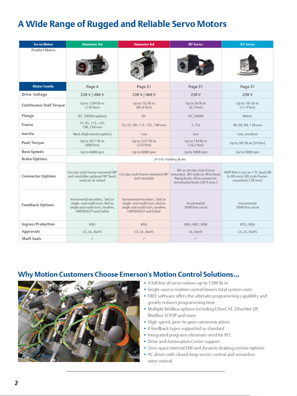
A
Wide
Range
Product Matrix
of
Rugged and Reliable Servo
Ummotorfm
Motors
Motor Family
Drive Voltage
Continuous Stall Torque
Flange
Frame
Inertia Med. (high inertia option)
Peak Torque
Base Speeds
Brake Options
Circular style frame-mounted 90' . •
Connector Options
Feedback Options
Ingress Protection
Approvals
Shaft
Seals
and rotatable· optional 90,
Incremental encoders,
single- and multi-tum,
single and multi-turn,
Page4
230V
/460V
Up
to
1204 lb-in
(136Nm) (85.0Nm) (6.3
IEC
(NEMA
option)
75, 95, 115, 142,
190,250
mm
Up
to
3611
lb-in
(408Nm) (255Nm) (16.2
Up
to
6000 rpm
vertic;I or mixed ' and rotatable
• terminated leads (20 ft max.)
HIPERFACE
• and
IP65 IP65
CE,
UL,
✓ ✓ ✓
fixed
SinCos
SinCos
resolver,
EnDat
RoHS
Page
21
230V / 460V
Up
to
752 lb-in
IEC
55, 67, 89, 115, 142, 190 mm
Low Low
Up
to
2257 lb-in
Up
to
6000 rpm
24
Vdc
Holding
Circular style frame mounted 90 mou~ted,
Incremental encoders,
single- and multi-tum,
single and multi-turn, resolver, 2048 line count
HIPERFACE•
CE,
UL,
and
RoHS
SinCos
SinCos
EnDat
Page31
230V
Up
to
56
Nm)
IEC,NEMA
2,3
Up
to
144 lb-in
Up
to
5000 rpm
Brake
MS
or circular style fra'."e
MS
ftym~
s~le
leads, dnve connector
Incremental
IP65,
IP67,
UL,
RoHS
lb-in
in
Nm)
on 40-,n lead,
IP68
Page37
Up
to 1 01
(11.4Nm)
40, 60, 80, 130 mm
Low,medium
Up
to
301
Up
to
AMP
Mat-n-Loc
to
80 mm);
mounted (130 mm)
Incremental
2048 line count
IP55,
CE,
230V
lb-in
Metric
lb-in
(34
5000 rpm
on 1-ft. lead (40
MS
style frame-
IP65
UL,
RoHS
Nm)
Why
2
Motion
Customers Choose Emerson's
• A
• Single-source motion control lowers total system costs
•
FREE
greatly reduces programming time
• Multiple
Modbus
• High-speed, peer-to-peer communications
• 8 feedback types supported as standard
• Integrated programs eliminate need for
•
Drive
• Zero-space internal
•
AC
rotor control
Motion
full
line of servo motors
software offers
Control Solutions ...
up
to
1200 lb-in
the
ultimate programming capability and
field
bus options including
TCP/IP
and more
EtherCAT,
EtherNet
PLC
and Automation Center support
EMI
and dynamic braking resistor options
drives with closed-loop vector control and sensorless
1/P,
Page 5
Drive and
Motor
Selection
Emerson Industrial Automation drive
an
provide
cost
optimized system
and
ease
components
of
use.
using
You
the
in
can manually select
following steps,
terms
and
of
ratings, performance,
or
SERVOSof~ sizing software which includes
Techniques' brand
1. Determine
the
requirements
motor
data
tables
determine
the
2. Once
a specific
speed. Make
which
application.
the
motor
motor
note
requirements
3.
Check
the
specification tables
servo drive
application's continuous
at
various
and
motor
family
model
of
the
of
the
selected motor.
and
motor
motor
shaft speeds,
the
visual reference overview
family
will
be
is
selected, use this brochure
that
delivers
continuous
the
and
in
the
Control Techniques'
of
brand individual drive brochures for Digitax
Unidrive
that
Mor
delivers
MDS
servo drives
adequate
to
continuous
select
and
selected motor.
4. Refer
5.
to
select
the
motor
Confirm
Note: A
the
Servo Motor Cables section
motor
power and feedback cables for
and
drive.
that
the
ratio
of
rotor
load
inertia/rotor
gear
reducer
will
reduce
inertia
to
inertia
the
load inertia based
following equation:
Reflected
Note: When specifying a
such options
other
as
options
load
user-interfaces
and
accessories
inertia = load
motor
system,
(HMI),
that
will
inertia/gear
be
braking resistors
enhance
performance and value.
motor
combinations
the
system
download
our
the
Control
data.
and
peak
torque
then
refer
to
most
appropriate for
to
required
torque
peak current (Amps)
ST,
Epsilon
the
drive model
peak
torque
for
of
this brochure
the
selected
load inertia
is
<10:1
<10
1
ratio
sure
to
consider
and
the
system's
to
help
select
and
EP,
the
to
on
the
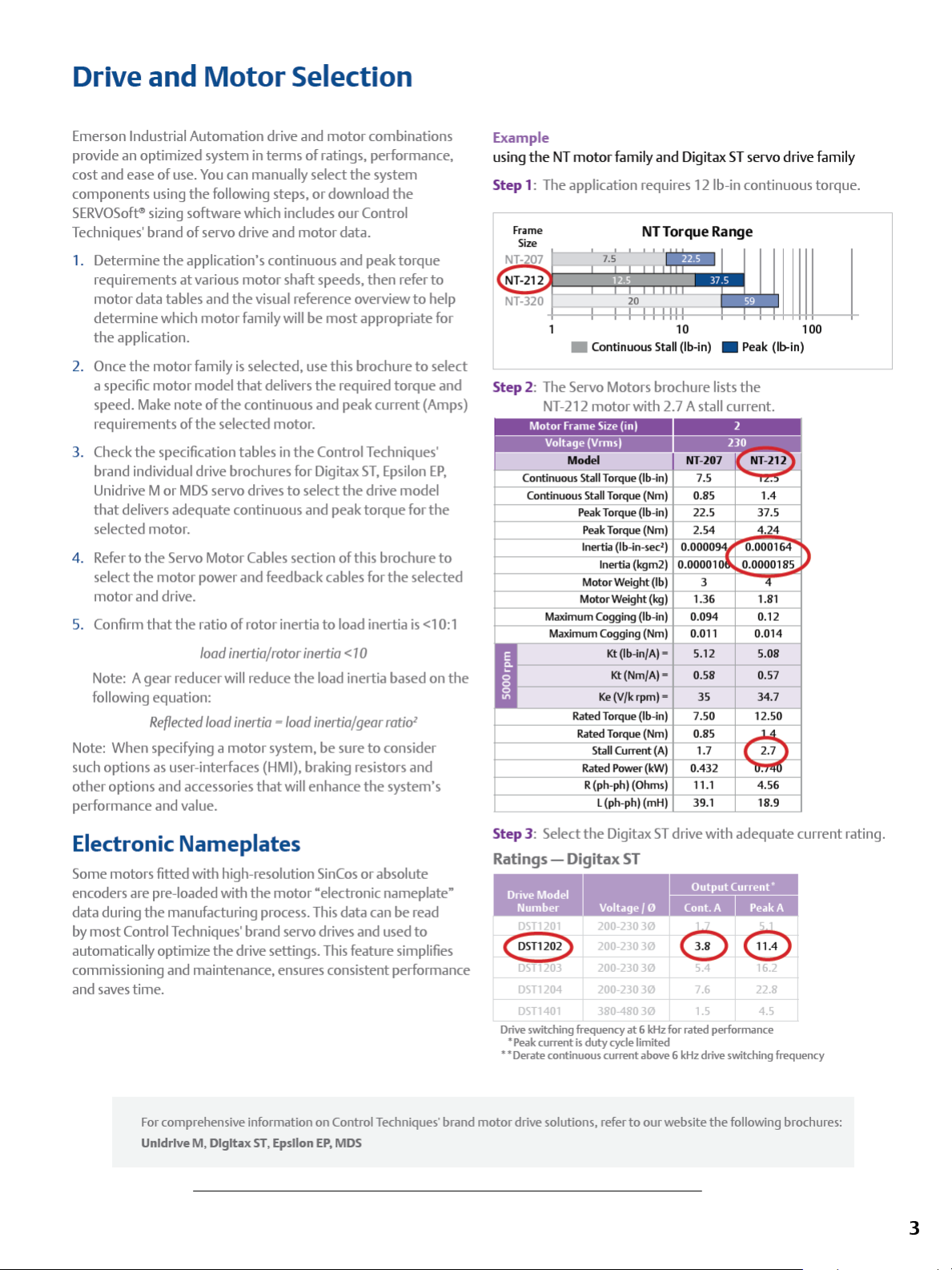
Example
the
NT
motor
family
and
using
Step 1: The application requires
• Continuous Stall (lb-in) •
Digitax ST servo drive family
12
lb-in continuous torque.
NT To
rqu
e Range
10 100
Step 2: The Servo Motors brochure lists
NT-212
motor
with 2.7 A stall current.
Continuous Stall Torque (lb-in)
Continuous Stall Torque (Nm) 0.85
Peak Torque (lb-in)
PeakTorque(Nm)
Inertia (lb-in-sec')
Inertia (kgm2)
Motor Weight (lb)
Motor Weight (kg)
Maximum Cogging (lb-in)
Maximum Cogging (Nm)
Kt
(lb-in/A)=
Kt(Nm/A) =
Ke
(V/k
rpm)=
Rated Torque (lb-in)
Rated Torque (Nm) 0.85
Stall Current
Rated Power (kW)
R (ph-ph) (Ohms)
L (ph-ph) (mH)
0.094
0.011
(A)
0.432
7.5
22.5
2.54
3
1.36
5.12
0.58 0.57
35
7.50
1.7
11.1
39.1
Peak
the
(lb-in)
1.81
0.12
0.014
5.08
34.7
12.50
4.56
18.9
Electronic Nameplates
Some motors fitted with high-resolution SinCos
the
encoders are pre-loaded with
data
during
the
manufacturing process. This data can
by
most
Control Techniques' brand servo drives and used
automatically optimize
the
motor "electronic nameplate"
drive settings.
commissioning and maintenance, ensures consistent performance
and saves time.
For comprehensive information
Unldrlve M, Dlgltax
ST,
Epsllon
or
absolute
be
read
to
This
feature simplifies
on
Control Techniques' brand
EP,
MOS
Step 3: Select
Ratings - Digitax
i·ifii
DST
<§3)
DST
DST1204 200-230
DST
Drive switching frequency
• Peak current
• • Derate continuous current above 6 kHz drive switching frequency
motor
drive solutions, refer
20
203
40
the
200-230
200-230
200-230
380-48030
is
duty
Digitax
ST
drive with
ST
Output
I .
f.
~
30
30
0 e
30
30
at
6 kHz for rated performance
cycle limited
to
our
5.4
7.6
1.5
website
adequate
Current'
6.2
22.8
4.5
the
following brochures:
current rating.
3
Page 6
Unimotor fm 230 V /
460
V
Flexible Configuration
Unimotor fm
motor
drives.
accommodate
available
and
motor
to
function as
partner
Key Features
• Torque range:
• Medium inertia design with high inertia option available
•
Connector
90° rotatable
• Variety
• Holding brake option
• IP65 conformance
• Winding
Speed
•
• Multiple feedback options:
• Resolver: Robust for
conditions - lower accuracy,
• Incremental encoder: High accuracy,
• Absolute: Medium accuracy,
and
• SinCos/Absolute: High accuracy, high resolution, single-turn
and
•
HIPERFACE
supported
is
a high performance, brush less
range
matched for use with Control Techniques' brand
"FM"
stands
for "Flexible Motor"
a wide range
in
six
frame sizes with various mounting
lengths. Emerson drives
an
optimized system.
for
Un
id
rive M, Digitax
12.4
to
1204
styles include vertical, low profile and
of
flange possibilities
to
suit
230
V and
options include 2000,
extreme
multi-turns
multi-turn
(SICK)
and
EnDat (Heidenhain) protocols
AC
Servo
and
of
applications. The
and
motors
Uni
motor
ST
and
Epsilon
lb-in
(1.4
to
(IEC/NEMA)
460
V
3000,
4000
applications
medium
medium
Motors
AC
Servo
is
designed
are designed
fm
EP
136.0
and
6000
and
resolution
medium
resolution, single-turn
to
motors
are
arrangements
is
the
perfect
servo drives.
Nm)
rpm
resolution
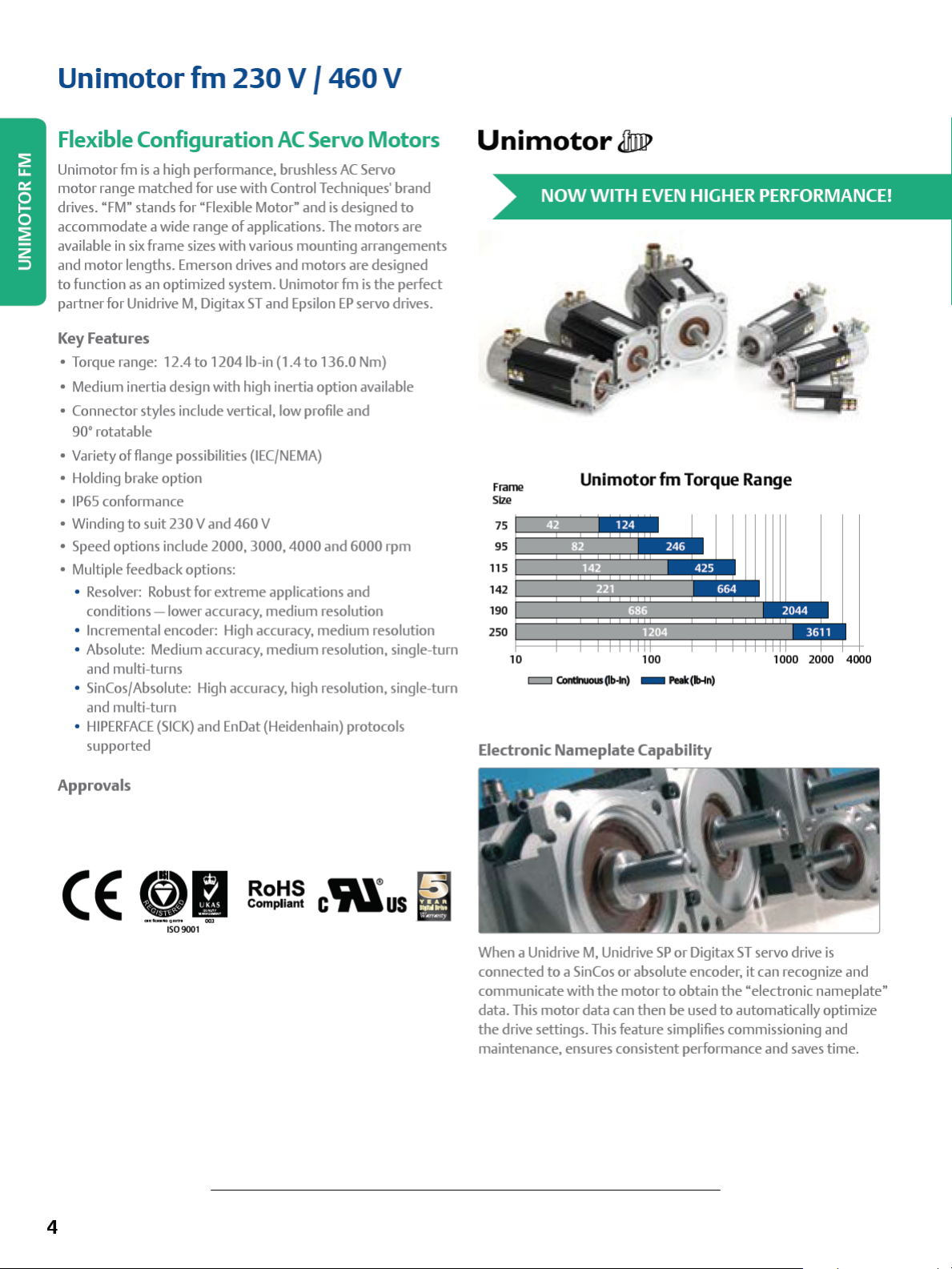
Unimotor
NOW
WITH
Fr
ame
Size
75
95
11
5
14
2
90
1
250
~==:i:::::=i=:::i:::::i::::i::::1
10 1
c:::::::J
Electronic
Unimotor
Conlhlous0b•ln) - Fak
Nameplate
J/Im>
EVEN
fm
p:i:1=
=:i:::::=i=:::i:::::i~i::::i::i:
00
Capability
HIGHER
PERFORMANCE!
Torque Range
1
000
(lb-ln
)
~~~
2000 4000
u
Approvals
( (
4
f/)fJ
IS09001
~!!~
c'i\lus
~
When a Unidrive
connected
communicate
data.
the
maintenance, ensures consistent performance and saves time.
M,
Unidrive
to a Sin
Cos
with
the
This
motor
data
drive settings. This feature simplifies commissioning
SP
or
or
absolute encoder,
motor
to
obtain
can
then
be
used
Digitax
ST
servo drive
it
can
the
"electronic nameplate"
to
automatically optimize
recognize
is
and
and
Page 7

095 U3 A
Frame
size
075
095
115
142
190
250
Motor
voltage
075-190
Fram
E3
U3
250
U3
es
= 230V
=460V
Frame
• 460V
Stator
le
075
Frame
-
095
-142
Fram
-
-
-
-
-
-
1
Frame
-
-
-
-
-
-
-
-
-
250
Frame
-
-
-
---
ngt
A
B
C
D
A
B
C
D
E
90
A
B
C
D
E
F
G
H
D
E
F
h
075-190
20=
30=
40•
60
250Frame
es
10 •
15 = 1500
20 •
25 • 2500
30
Rated
speed
(rpm)
Fram
•
075-250 075-1
Frames Frames Frames
es
0=No
2000
3000
5 =24
Parking
4000
6000
•
1000
2000
maybe removed
Hybrid
standa
PooerConnector
Refer
5
Brake Connection type
42
B=Pooerand
Brake
gnal 90•
size
and
l vertical
1.0
gna
l Vertical
1.0
90
Fram
signal 90rotatable
1.5
Power
gna
l Vertical
1.5
and
l vertical
1.5
Frames
Power
and signa
ca
l
250Frame
Power
and signa
cal (Std)
once
the motor Is I
on
"
Ratings
Size
and
1.0
es
and
hybrid
l
hybrid
l
H"-
Due
on
type
-Due
Reference Tables.
Si
rotatable
Vdc
brake
C=Pooer90°
rotatable
signa
size
V=Powerand
Si
size
142-1
J =Pooer go•
and
and
size
M =
Si
size
N= Power90°
rotatable
signa
size
115-190
H =
box
verti
H =
box
verti
Box
Connecti
rd
power connecti
to
the Connector
Output shaft
075-250
A=Keywayw/
Fu
ll
Key installed
B=NoKeyway
E• =Keywayw/
Ha
lf
Key installed
F• • Keywayw/
Ha
lf
and Full
included
nstalled.
to
the Incr
on
some
115
to
the i
ncreased
AE = Reso
CA= Incremental Encoder
EB
= Opti
FB = Opti
EC= Inductive
FC = Inductive
RA
= Optical Sl
Key
SA
=Optical Sl
AE
=
Reso
CA= Incremental Encoder (S
EB
= Opti
FB = Opti
RA
= Optical Sl
SA
= Optical Sl
Cable length
length
requirements.
eased
power rati
and
power ratings
190
ngs
frames.
Feedback
42
075-1
lver
ca
l Absolute Multi-turn
cal Abso
lute SI ngle tum
Abso
lute Multi-turn
Abso
lute Single t
nCos
Multi-turn
nCos
Single t
190-250Frames
lver
ca
l Absolute Multi-turn
cal Abso
lute Single tum
nCos
Multi-turn
nCos
Single turn
res
tricti
ons
appl
now
available
on
noo
availab
le
(E3/U3
device
Fram
es
(Std)
EnDa
EnDa
urn
HIPERFACE
urn
HIPERFACE
td)
EnDa
EnDa
HIPERFACE
HIPERFACE
y.
Refer to cable
the
E3/U3
motors),
4096ppr
t
EQN1325
t
ECN1313
EnDa
t
EQI
1331
EnDa
t ECl1319
SRM
50
SRS50
4096ppr
t
EQN1325
t
ECN1313
SRM 50
SRS50
section
motors a hybrid box Is
some
power connector
A=
B=Hl
C =
KTY84-130
thermistor
D=High+
KTY84-130
thermistor
for
Rotor Inertia +
Thermlster
075-250 Fram
Type
Standard + PTC
gh
+PTC
Sta
ndard+
noo
the
have
changed
es
Bol
tClrd
-
Diameter
(BCD)
075 Fram e
075
080
085 Opt
095 Frame
00
1
098
115 Opt
115
Frame
11
5
130 Opt
1
42
Frame
165
149
1
90
Frame
215
250
Frame
3
00
.
Std
Opt
Std
Opt
Std
Std
Opt
Std
Std
e
11
1
190
140
1
240
190
240
240
240
320
3201
320
380
480
Shaft Diameter
(ex. 110=
Shaft
Length
(mm)
075Frame
0
23
40
30
40
095F
30
90
40
50
115Frame
40
50
50
1
42
Frame
50
58
1
90
Frame
80
58
58
250F
110
11.0mm)
Frame
Length
B-D
rame
B-E
A-C
D,E
A-E
D,E
1
A
A
rame
D·F
C
V,
C:
/1)
,.,.
::I
:::r
/1)
-·
:5·
3
o'
-,
0
:3
,....
,.,.
"'
o·
0
..,
::,
O'"
/1)
....
0
:E
,.,.
0
,..,
ii,
,.,.
"'
/1)
::,
"'
0
0...
~
,..,
0
Cl..
/1)
Q
"'
C
::,
!!i'
0
,.,.
~
......
:3
";::;:-
0
"O
0
:E
;;;;·
::,
"'
/1)
X
"'
:3
"O
3
0
..,
C.
tt)
..,
-
::I
....
0
..,
3
0.t
,....
-·
0
::I
A
A
1
-H
·H
~
V1
1/\1.:1
MOlOI/\IINn
Page 8
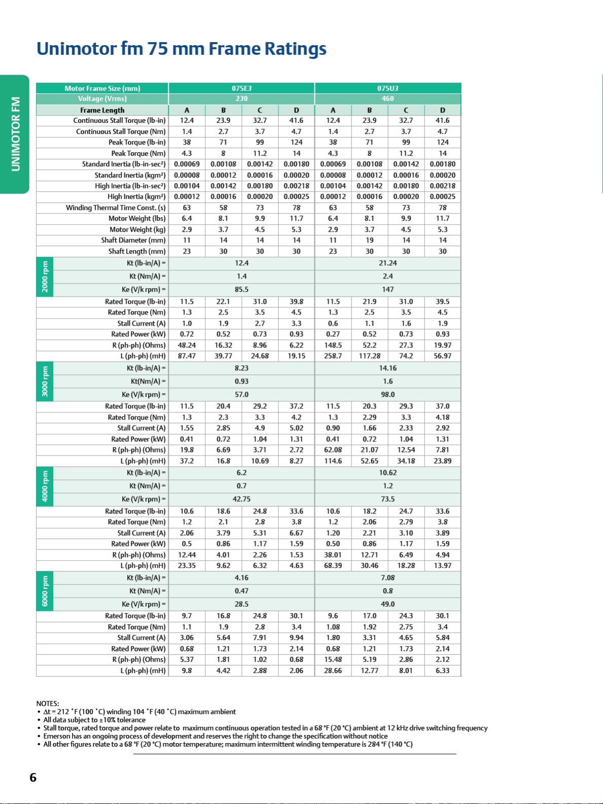
Unimotor
Motor
Frame Size
Voltage (Vrms)
Frame
length
Continuous Stall Torque (lb-in)
Winding Thermal Time Const. (s) 63
.
!:
-
-
~
!:
-
..
~
!:
-
-
Ii,
~
!:
-
-
Continuous Stall Torque (Nm)
Peak Torque (lb-in)
Standard Inertia (lb-in-
Standard Inertia (kgm') 0.00008 0.00012 0.00016 0.00020 0.00008 0.00012 0.00016 0.00020
High
Inertia (lb-in-
High Inertia (kgm') 0.00012 0.00016 0.00020 0.00025 0.00012 0.00016 0.00020 0.00025
Motor Weight (lbs)
Motor Weight (kg)
Shaft Diameter
Shaft
Rated Torque (lb-in)
Rated Torque (Nm)
Rated Torque (lb-in)
Rated Torque (Nm)
Rated Torque (lb-in) 10.6 18.6 24.8
Rated Torque (Nm)
Rated Torque (lb-in)
Rated Torque (Nm) 1.1
fm
75
mm
(mm)
Peak Torque (Nm)
sec')
0.00069 0.00108 0.00142 0.00180 0.00069 0.00108 0.00142 0.00180
sec')
0.00104 0.00142 0.00180 0.00218 0.00104 0.00142 0.00180 0.00218
(mm)
length
(mm)
Kt
(lb-in/A) =
Kt(Nm/A) =
Ke
(V/k rpm) = 85.5 147
Stall Current
Rated Power (kW)
R (ph-ph) (Ohms)
L (ph-p
Ke
Stall Current
Rated Power (kW) 0.41 0.72
R (ph-ph) (Ohms)
L (ph-p
Ke
Stall Current
Rated Power (kW) 0.5 0.86 1.17 1.59 0.50 0.86 1.17 1.59
R (ph-ph) (Ohms)
L (ph-ph) (mH)
Ke
Stall Current
Rated Power (kW)
R (ph-ph) (Ohms)
L (ph-p
(A)
48.24
h)
(mH)
87.47
Kt
(lb-in/A) = 8.23 14.16
Kt(Nm/A) = 0.93 1.6
(V/k rpm) = 57.0 98.0
(A)
h)
(mH)
Kt
(lb-in/A) = 6.2 10.62
Kt(Nm/A) = 0.7 1.2
(V/k rpm) = 42.75 73.5
(A)
12.44
23.35 9.62 6.32 4.63 68.39
Kt
(lb-in/A) = 4.16 7.08
Kt(Nm/A) = 0.47 0.8
(V/k rpm) = 28.5 49.0
(A)
h)
(mH)
Frame Ratings
075£3 075U3
A B C D A B C D
12.4
1.4
38
4.3
6.4 8.1 9.9 11.7 6.4 8.1 9.9 11.7
2.9
11
23
11.5 22.1
1.3 2.5
1.0 1.9
0.72 0.52 0.73 0.93 0.27 0.52 0.73 0.93
11.5 20.4 29.2
1.3 2.3
1.55 2.85
19.8 6.69 3.71 2.72
37.2
1.2 2.1
2.06
9.7
3.06
0.68 1.21 1.73 2.14 0.68 1.21 1.73 2.14
5.37
9.8 4.42 2.88 2.06 28.66 12.77
23.9
2.7
71
8 11.2
58
3.7
14 14 14
30 30 30
16.32 8.96 6.22 148.5 52.2 27.3 19.97
39.77
16.8 10.69 8.27 114.6 52.65
3.79
4.01 2.26 1.53 38.01 12.71 6.49
16.8 24.8 30.1 9.6 17.0 24.3 30.1
1.9
5.64
1.81 1.02 0.68
32.7
3.7
99
73
4.5 5.3
12.4
1.4
31.0
3.5
2.7
24.68 19.15 258.7 117.28 74.2 56.97
3.3
4.9
1.04
2.8
5.31 6.67 1.20 2.21
2.8
7.91 9.94 1.80 3.31 4.65
41.6
4.7
124
14
78
39.8
4.5 1.3 2.5
3.3
37.2
4.2 1.3 2.29
5.02 0.90 1.66 2.33 2.92
1.31 0.41 0.72
33.6
3.8
3.4
12.4
1.4
38
4.3 8 11.2
63
2.9
11
23
11.5 21.9
0.6 1.1 1.6
11.5 20.3 29.3
62.08
10.6 18.2 24.7
1.2 2.06 2.79
1.08
15.48
•,
I
23.9
2.7
71
58
3.7
19 14 14
30 30 30
21.07
30.46
1.92 2.75
5.19 2.86 2.12
32.7
3.7
99
73
4.5 5.3
21.24
2.4
31.0 39.5
3.5
3.3
1.04
12.54
34.18
3.10 3.89
18.28
8.01
41.6
124
37.0
4.18
1.31
7.81
23.89
33.6
4.94
13.97
5.84
6.33
4.7
14
78
4.5
1.9
3.8
3.4
NOTES:
•
&t
= 212 °
F(l00
All
data
•
• Stall torque, rated torque and power relate
• Emerson has an ongoing process
All
other
•
'CJ winding 104 °F (40
subject
to
:t 1
figures relate
0%
tolerance
to a 68
of
'F (20 '
6
°CJ
maximum ambient
to
development and reserves
maximum continuous operation tested
CJ
motor
temperature; maximum intermittent winding
the
right
to
change
in a 68
'F
(20
'CJ
the
specification without notice
temperature
ambient
is
at
12
kHz drive switching frequency
284
'F
(140
'CJ
Page 9
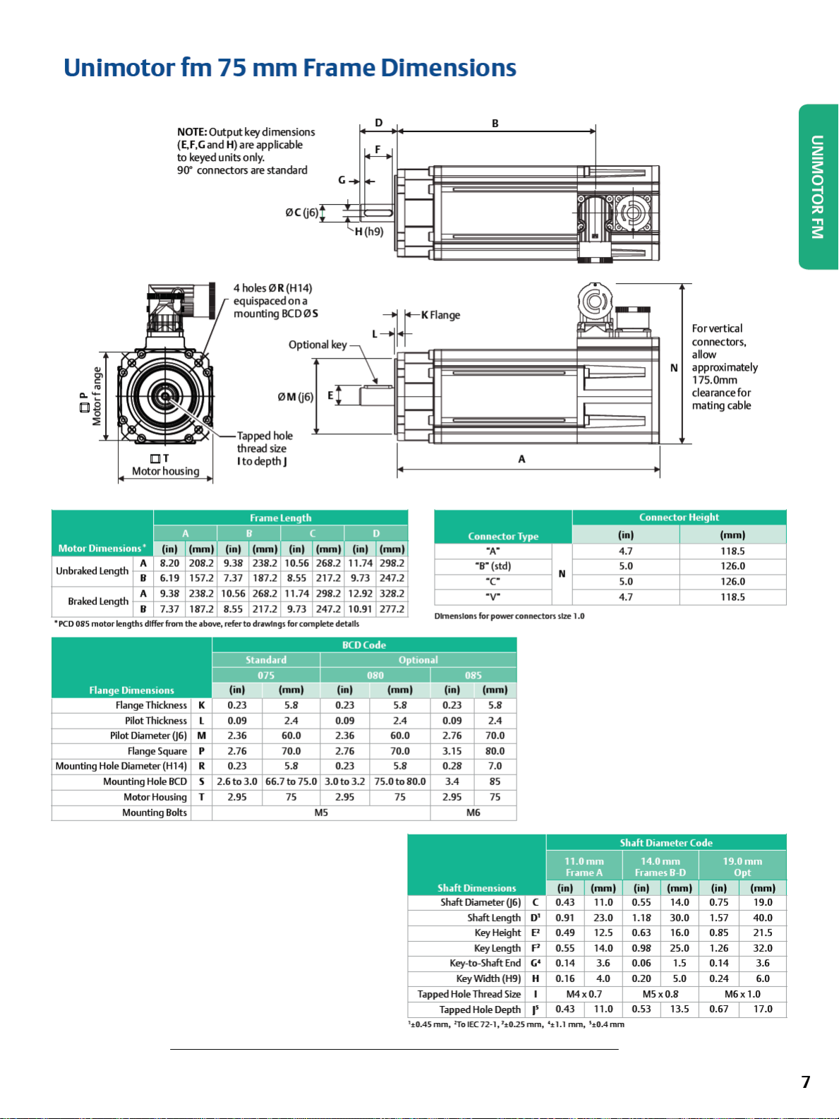
Unimotor
fm
75
mm
Frame Dimensions
NOTE:
Output
(E,F
,Ga
nd
to
90-
H) a
keyed units only.
connectors a
key dimensions
re
applicable
re
standard
4holes0R(H14)
equispaced
mounting
Tapped hole
thread
l
todepthJ
on
BC00
Opti
0Mij6
size
D
F
G
H (h9)
a
S
ona
)
lkey\
E!
LI
\
r
~KFl
~
L
-
-
r
ange
B
(Q>
~
~1
,.,,
I
I
I
I
A
For vertical
connectors,
allow
approximately
N
175.0mm
clearance
mating cable
for
Unbraked Length
Braked Length
•peo
085 mot
or
lengths differ from
Flange Thickness K 0.23 5.8 0.23 5.8 0.23 5.8
Pilot Diameter 06) M 2.36 60.0 2.36 60.0 2.76 70.0
Mounting
Hole
Mounting Hole
Connector Type
A
B
6.19 157.2
9.38 238.2
A
B 7.37 187.2 8.55 217.2 9.73 247.2 10.91 277.2
Pilot Thickness
Flange Square
Diameter (H14) R 0.23 5.8 0.23 5.8 0.28 7.0
BCD
Motor Housing
Mounting Bolts
7.37 187.2 8.
10.56 268.2 11.74
the
above, r
efer to
l 0.09 2.4 0.09 2.4 0.09
p
2.76 70.0 2.76 70.0 3.15 80.0
s
2.6to
3.0
T 2.95 75 2.95 75 2.95 75
drawings for
66.7to
55
217.2 9.73 247.2
298.2 12.92 328.2
comple
te details
75.0
3.0to3.2
MS
75.0to80.0
1
±0.45 mm, 2To I
Dimensions
Shaft Dimensions
Shaft Diameter 06) C
Tapped
Tapped
"B"
for
3.4
M6
Shaft
Key
Key
Key-to-Shaft
Key
Width (H9)
Hole Thread
Hole
EC 72-
"A"
(std)
·c
·v·
power connectors
2.4
85
length
Height
length
D' 0.91
E1
p
c;•
End
H 0.16
Size
Depth
I'
1, 1:t:0.25 mm,
(inl
4.7
N
size 1.0
11.0mm 14.0mm 19.0mm
Frame A Frames
5.0
5.0
4.7
Shaft Diameter Code
B-D
lfflllll!
23.0 1.18
0.49 12.5 0.63 16.0 0.85 21.5
0.55 14.0 0.98 25.0 1.26
0.14 3.6 0.06 1.5 0.14 3.6
4.0
M4x0.7
0.43 11.0 0.53 13.5 0.67 17.0
':t:
1.1 mm
, 5:t:0.4
mm
30.0
0.20 5.0 0.24 6.0
M5x0.8
innJ
1.57
(mml
118.5
126.0
126.0
118.5
Opt
M6x
1.0
40.0
32.0
7
Page 10
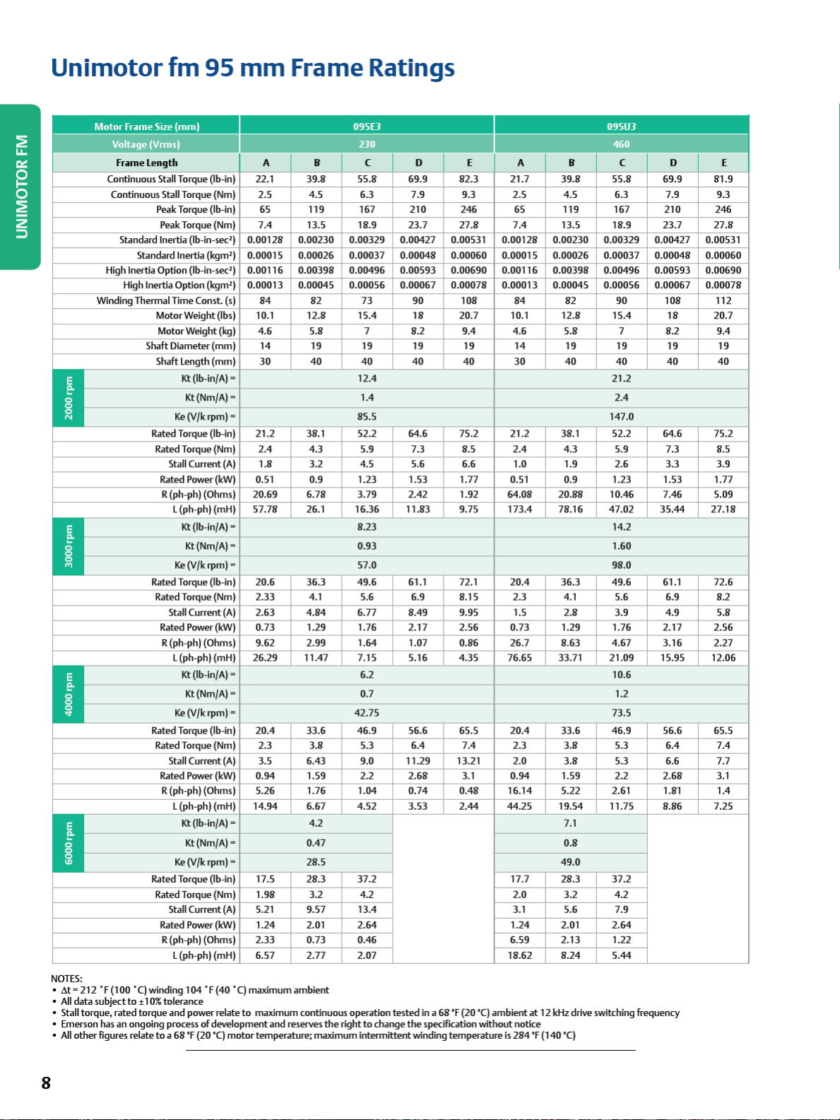
Unimotor
Motor
frame
Voltage (Vrmsl
fr
~me l ength A B C D E A B C D E
Continuous Stall Torque (lb-in)
Continuous Stall Torque (Nm) 2.5 4.5 6.3 7.9 9.3 2.5 4.5 6.3 7.9 9.3
Standard Inertia (lb-in-sec') 0.00128 0.00230 0.00329 0.00427 0.00531 0.00128 0.00230 0.00329 0.00427 0.00531
High Inertia Option (lb-in-sec') 0.00116 0.00398 0.00496 0.00593 0.00690 0.00116 0.00398 0.00496 0.00593 0.00690
High
Winding Thermal Time Const. (sl
.
-
-
-
.
-
-
-
I
I
NOTES:
•
.6.t
= 212 • f
(1
All
data subject
•
• Stall torque, rated torque and power relate
• Emerson has an ongoing process
•
All
other
00 •
figures relate
fm
95
Size
(mm)
Peak Torque (lb-in)
Peak Torque (Nm)
Standard Inertia
Inertia Option
Motor Weight (lbs)
Motor Weight (kg)
Shaft Diameter (mm)
Shaft
Rated Torque (lb-in)
Rated Torque (Nm)
Rated Power (kWl 0.51 0.9 1.23 1.53 1.77 0.51 0.9 1.23 1.53 1.77
R (ph-ph) (Ohms)
Rated Torque (lb-in)
Rated Torque (Nm)
Rated Power (kW)
R (ph-ph) (Ohms)
Rated Torque (lb-in)
Rated Torque (Nm)
Rated Power (kW)
R (ph-ph)(Ohms)
Rated Torque
Rated Torque (Nm)
Rated Power
R (ph-ph) (Ohms)
C)
winding 104 • f (40 •
to
• 10% tolerance
to a 68
(kgm'l
(kgm'l
length ( mm l 30
Kt
(lb-in/A)=
Kt(Nm/A) =
Ke
(V/k
rpm)=
Stall Current (A)
l (ph-ph) (mH)
Kt
(lb-in/A)= 8.23 14.2
Kt(Nm/A) = 0.93 1.60
Ke
(V/k
rpm)=
Stall Current
l (ph-ph) (mH)
Ke
Stall Current
l (ph-ph) (mH)
Ke
Stall Current
l (ph-ph) (mH)
(A
Kt
(lb-in/A)= 6.2 10.6
Kt(Nm/A) = 0.7 1.2
(V/k
rpm)=
(Al
Kt
(lb-in/A)= 4.2
Kt(Nm/A) = 0.47 0.8
(V/k
rpm)=
(I
b-in)
(A)
(kW)
of
development and reserves
'f (20 '
C)
mm
0.00015 0.00026 0.00037 0.00048 0.00060 0.00015 0.00026 0.00037 0.00048 0.00060
0.00013 0.00045 0.00056 0.00067 0.00078 0.00013 0.00045 0.00056 0.00067 0.00078
)
C)
maximum ambient
to
motor temperature; maximum intermittent winding temperature
Frame Ratings
095£3 095UJ
I
22.1 39.8
65 119 167 210 246 65 119 167 210 246
7.4
84
10.1
4.6
14
21.2 38.1 52.2 64.6 75.2 21.2 38.1 52.2 64.6 75.2
2.4
1.8
20.69 6.78 3.79 2.42 1.92 64.08
57.78 26.1 16.36 11.83 9.75 173.4 78.16 47.02 35.44 27.18
20.6 36.3 49.6 61.1 72.1
2.33
2.63
0.73 1.29 1.76 2.17 2.56 0.73 1.29 1.76 2.17 2.56
9.62 2.99
26.29 11.47 7.15 5.16 4.35 76.65 33.71 21.09 15.95 12.06
20.4
2.3
3.5 6.43 9.0 11.29 13.21 2.0
0.94 1.59 2.2
5.26 1.76
14.94 6.67 4.52 3.53
17.5 28.3 37.2 17.7 28.3 37.2
1.98
5.21 9.57
1.24
2.33 0.73 0.46 6.59 2.13 1.22
6.57 2.77 2.07 18.62
maximum continuous operation
13.5 18.9 23.7
82
12.8 15.4
5.8 7 8.2 9.4 4.6 5.8 7 8.2 9.4
19 19 19
40 40 40 40
4.3 5.9 7.3 8.5
3.2 4.5 5.6 6.6 1.0 1.9 2.6 3.3 3.9
4.1
4.84
33.6 46.9 56.6 65.5
3.8
28.5 49.0
3.2 4.2 2.0 3.2 4.2
2.01
55.8 69.9 82.3 21.7
27.8
73
12.4
1.4
85.5 147.0
57.0 98.0
5.6 6.9 8.15 2.3
6.77 8.49 9.95 1.5
1.64
42.75 73.5
5.3 6.4
1.04
13.4
2.64
the
right
to
90
18
1.07 0.86 26.7 8.63 4.67 3.16 2.27
2.68
0.74 0.48 16.14 5.22 2.61 1.81
tested
change
the
108
20.7 10.1
19 14 19 19 19 19
7.4
3.1 0.94 1.59 2.2
2.44
in a 68
'f (20 '
specification without notice
7.4
84
30
2.4
20.4
20.4
2.3
44.25 19.54 11.75 8.86 7.25
3.1 5.6 7.9
1.24
C)
ambient
is
284 'f (140 '
39.8
13.5 18.9 23.7
82
12.8 15.4
40 40 40 40
4.3 5.9 7.3 8.5
20.88 10.46 7.46 5.09
36.3 49.6 61.1 72.6
4.1
2.8
33.6 46.9 56.6 65.5
3.8
3.8
7.1
2.01
8.24
at
12
kHz
drive switching frequency
C)
460
55.8 69.9 81.9
90
21.2
2.4
5.6 6.9 8.2
3.9 4.9 5.8
5.3 6.4
5.3 6.6 7.7
2.64
5.44
108
18
2.68
27.8
112
20.7
7.4
3.1
1.4
8
Page 11
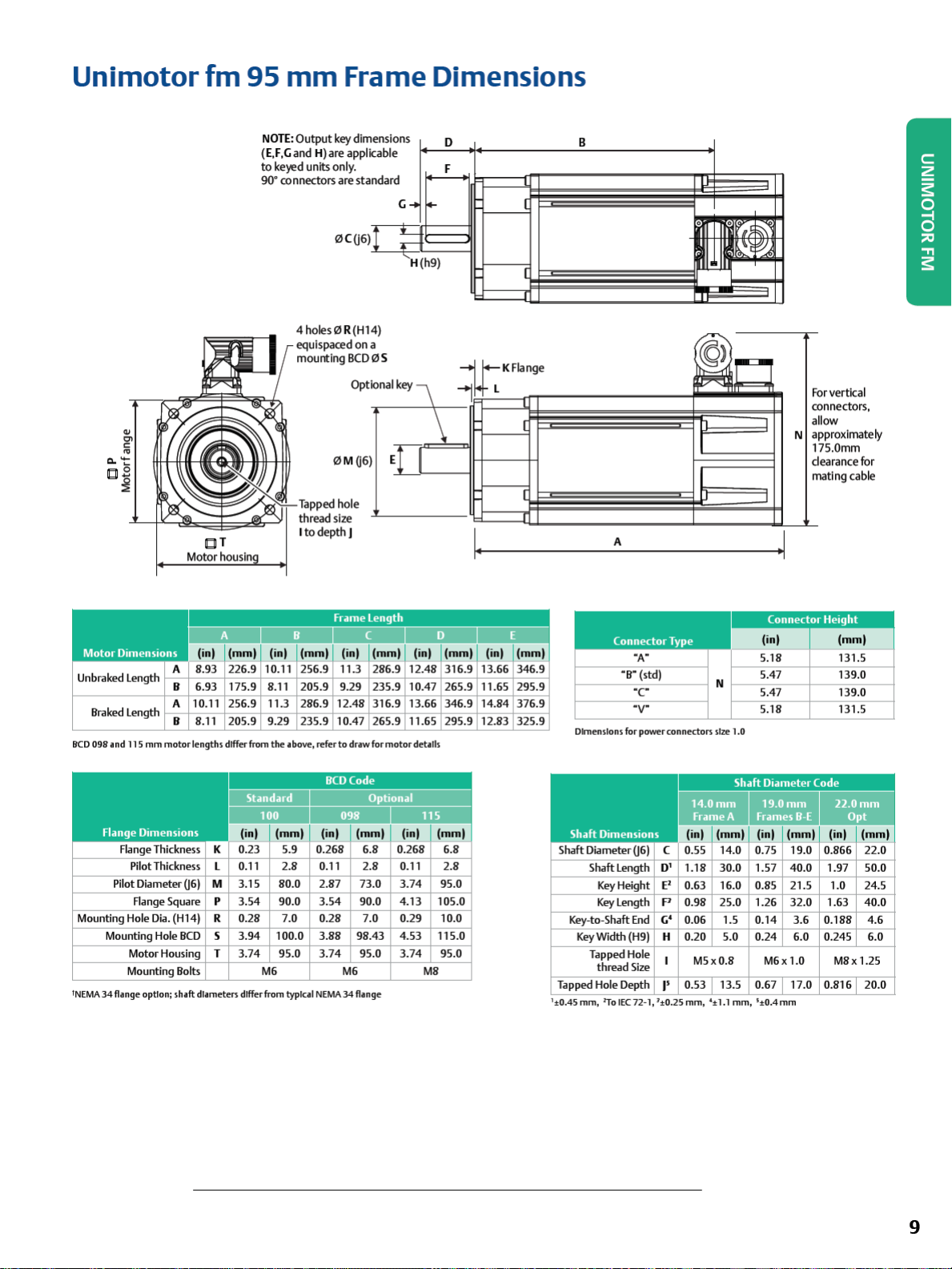
Unimotor
fm
95
mm
NOTE:
(E,F,Gand H
to
ke~d
90
° connectors are
Output
)are
units only.
Frame Dimensions
key dimensions
appl
kable
sta
ndard
0(06)
,t
G
➔
•
..
' H(h9)
~
~
D
F
l
I
B
I
0
11ilr,:
~'
1
11~
I 11
~
11
1
I
4 holes 0 R (Hl 4)
equispaced on
mounting
Tapped hole
thread size
C T
Motor housln
Unbraked Length
Braked Length
BCD
098
i nd 115
Flange Thickness K
Pilot Diameter 06) M 3.15 80.0 2.87 73.0 3.74 95.0
Mounting Hole
Mounting Hole
INEMA
34 flange option; sh•ft dl•met
A
B
6.93 175.9
A
10.11 256.9
B
8.11 205.9
mm
motor
lengths differ from the 1bove, refer
Pilot Thickness L 0.11 2.8 0.11
p
Range Square
Dia.
(H14)
BCD
Motor Housing T 3.74 95.0 3.74 95.0 3.74 95.0
Mounting Bolts
3.54 90.0 3.54 90.0 4.13 105.0
R 0.28 7.0 0.28
s 3.94 100.0 3.88 98.43
e"
differ from typical
It
8.11
11.3
9.29
M6
BCD
Opt
0M06
o depth J
205.9 9.29
286.9 12.48
235.9 10.47
to
drawformotordetills
M6 M8
NEMA
34 flange
)
2.8
7.0
a
0S
lonalkey \
~KFlange
1
\
EI]
235.9 10.47 265.9
316.9 13.66 346.9
265.9 11.65 295.9
0.11
2.8
0.29 10.0
4.53
115.0
I
I
11.65 295.9
14.84 376.9
12.83 325.9
I
I
A
"A"
"B"
(std)
·c
·v·
Dimensions
Shaft Dimensions
ShaftDiameter06) C
Key-to-Shaft
Tapped Hole Depth
1
:t0.4Smm, ?Jo1EC72-1,1:t0.25mm, '±1.1
Shaft Length
Key
Height E'
Key
length
Key
Width (H9) H
Tapped Hole
thread Size
for power
End
connectors
14.0mm
0.55 14.0
D'
1.18 30.0
0.63 16.0
p
0.98 25.0
G'
0.06 1.5
0.20 5.0
0.53 13.5
I'
©>
;
r=-
~
r-
I
I
I
I
N
size
1.0
Shaft Diameter Code
Frame A
mm
l
(
nl
M5x0.8
mm, s±0.4mm
N
_j
I
(inl
5.18
5.47
5.47
5.18
19.0mm
Frames
B-E
(inl (m
0.75 19.0
1.57 40.0
0.85 21.5
1.26 32.0
0.14 3.6
0.24 6.0
M6x
1.0
0.67 17.0
Forvertkal
connectors,
al
low
a
pproxlmately
75.0mm
1
earancefor
d
mating cable
(
mm
l
131.5
139.0
139.0
131.5
22.0mm
Opt
1.97 50.0
1.0
24.5
40.0
1.63
0.188
4.6
0.245 6.0
M8x 1.25
0.816 20.0
9
Page 12
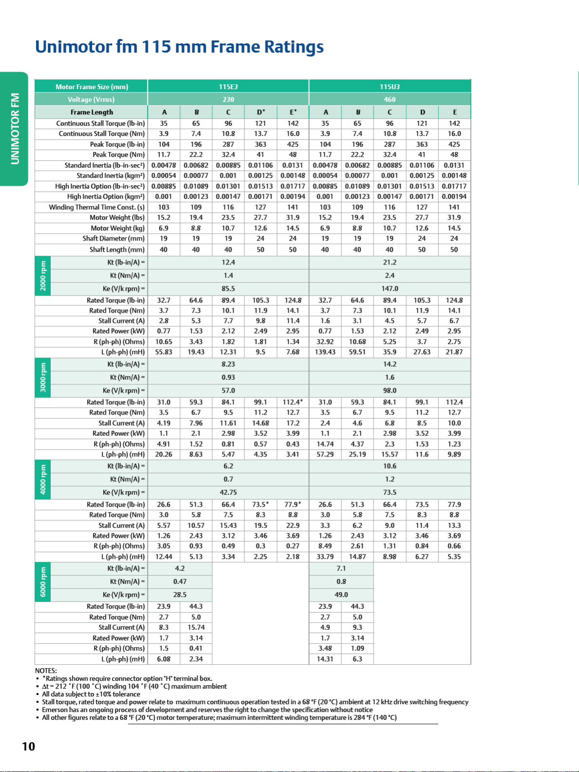
Unimotor
fm
115
mm
Frame Ratings
Motor Frame
Voltage (Vrmsl
Continuous Stall Torque (lb-in)
Continuous Stall Torque (Nm)
Standard Inertia (lb-in-sec') 0.00478 0.00682 0.00885 0.01106 0.0131 0.00478 0.00682 0.00885 0.01106 0.0131
High
High Inertia Option (kgm') 0.001 0.00123 0.00147 0.00171 0.00194 0.001 0.00123 0.00147 0.00171 0.00194
Winding Thermal Time Const. (s) 103 109 116 127 141 103
~
!:
-
~
•
R
Iii
~
!:
-
-
Iii
~
!:
-
-
NOTES:
• *Ratings shown require connector option
.6.t = 212
•
•
All
data
subject
• Stall torque, rated torque and power relate
• Emerson has an ongoing process
•
All
other
figures relate
Size (
mml
Frame L
engt
h A B C
35
3.9
Peak Torque
Peak Torque (Nm)
Standard Inertia (kgm') 0.00054 0.00077 0.001 0.00125 0.00148 0.00054 0.00077 0.001 0.00125 0.00148
Inertia Option (lb-in-sec') 0.00885 0.01089 0.01301 0.01513 0.01717 0.00885 0.01089 0.01301 0.01513 0.01717
Motor Weight (lbs) 15.2
Motor Weight (kg)
Shaft Diamet
Shaft Length (mm) 40
Rated Torque (lb-in)
Rated Torque (Nm)
Rated Power
R (ph-ph) (Ohms)
Rated Torque (lb-in)
Rated Torque (Nm)
Rated Power
R (ph-ph) (Ohms)
Rated Torque (lb-in)
Rated Torque (Nm)
Rated Power
R (ph-ph) (Ohms)
Rated Torque (lb-inl 23.9 44.3 23.9 44.3
Rated Torque (Nm)
Rated Power
R (ph-ph) (Ohms)
• F (1
00
•
CJ
to • 10%
(I
b-in)
104
11.7 22.2
19.4
6.9
er
(mm) 19 19
Kt
(lb-in/A)= 12.4 21.2
Kt(Nm/A) = 1.4 2.4
Ke
(V/k
rpm)=
32.7
3.7
Stall Current
L (ph-ph) (mH)
Ke
Stall Current
L (ph-ph) (mH)
Ke
Stall Current
L (ph-ph) (mH)
Ke
Stall Current
L (ph-ph) (mH)
winding 104 • F (40 •
(A)
2.8
(kW)
0.77 1.53 2.12 2.49 2.95 0.77 1.53 2.12 2.49 2.95
10.65
55.83 19.43 12.31 9.5 7.68 139.43 59.51
Kt
(lb-in/A)=
Kt(Nm/A) = 0.93 1.6
(V/k
rpm)=
31.0
3.5
(A)
4.19 7.96 11.61 14.68 17.2 2.4
(kW)
1.1
4.91 1.52 0.81 0.57 0.43
20.26 8.63 5.47 4.35 3.41 57.29 25.19 15.57 11.6 9.89
Kt
(lb-in/A)= 6.2 10.6
Kt(Nm/A) = 0.7 1.2
(V/k
rpm)=
26.6 51.3 66.4
3.0
(A)
5.57 10.57 15.43 19.5 22.9
(kW)
1.26 2.43
3.05
12.44 5.13
Kt
(lb-in/A)= 4.2 7.1
Kt(Nm/A) = 0.47 0.8
(V/k
rpm)=
2.7
(A)
8.3
(kW)
1.7
1.5 0.41
6.08 2.34 14.31 6.3
tolerance
of
to a 68
development and reserves
'F (20
'CJ
motor temperature; maximum intermittent winding
64.6
3.43
59.3 84.1 99.1
0.93 0.49 0.3 0.27
28.5 49.0
15.74
3.14
"H"
terrninal box.
CJ
maximum
to
maximum continuous operation
115£3
o•
65
7.4 10.8 13.7 16.0
196
8.8
40
7.3 10.1 11.9 14.1
5.3 7.7 9.8
6.7 9.5 11.2 12.7
2.1
5.8
5.0
96
287
32.4
23.5 27.7
10.7 12.6 14.5 6.9
19
40
85.5 147.0
89.4
1.82 1.81 1.34
8.23
57.0 98.0
2.98
42.75 73.5
7.5
3.12 3.46 3.69
3.34
ambient
the
121 142
363
105.3
3.52 3.99
73.5*
8.3
2.25 2.18
right
to
41
24 24
so so
change
E*
425
48
31.9
124.8
11.4
112.4
77.9·
8.8
tested
in a 68
the
specification without notice
11SU3
•
,I
A B C D E
35
3.9
104 196
11.7 22.2
15.2
19
40 40 40
32.7
3.7
1.6 3.1 4.5 5.7 6.7
32.92
•
31.0
3.5
1.1 2.1 2.98
14.74
26.6 51.3 66.4 73.5 77.9
3.0
3.3
1.26 2.43
8.49
33.79
2.7 5.0
4.9
1.7
3.48
'F (20 '
temperature
65
7.4 10.8 13.7
109 116
19.4
8.8
19 19
64.6
7.3 10.1 11.9 14.1
10.68 5.25
59.3 84.1 99.1
6.7 9.5 11.2 12.7
4.6
4.37 2.3 1.53 1.23
5.8 7.5
6.2 9.0 11.4 13.3
2.61 1.31 0.84 0.66
14.87 8.98 6.27 5.35
9.3
3.14
1.09
CJ
ambient
is
284
96
287
32.4
23.5 27.7
10.7 12.6 14.5
89.4
35.9
14.2
6.8
3.12 3.46 3.69
at
12 kHz drive switching frequency
'F
(140 '
121 142
363
127 141
105.3
3.7
27.63 21.87
8.5
3.52 3.99
8.3
CJ
41
24
so
16.0
425
48
31.9
24
so
124.8
2.75
112.4
10.0
8.8
10
Page 13
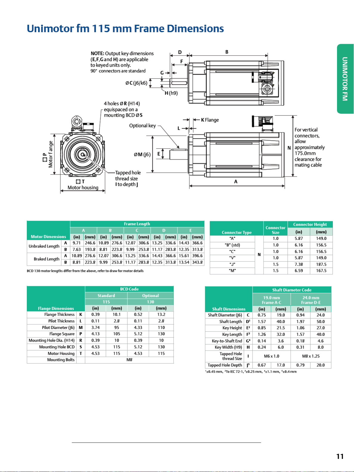
Unimotor
fm
115
mm
Frame Dimensions
4)
Cl
C:
"'
Cl. -
as
~
NOTE
(E,F
to
90• connectors are standard
OT
Motor housin
: Output key dimensions
,Gand
H)
are
keyed
applicable
units only.
0C(j6/k6)
4 holes 0 R (Hl 4)
equispaced
mounting
on
a
BCD
Optiona
0S
0M(j
thread
size
I todepthJ
Ikey~
ill
6)
G
H(h9)
D
L-J
\.
F
¥KF1ange
-
~
-l-1"
B
~
I
-
-==-
I
I
A
I
J
F or vertical
C
onnectors,
al
low
a
pproximately
N
1
75.0mm
leara
C
mating
nee
cable
for
Unbraked Length
Braked Length
IICD
130
motor lengths
Flange Thickness
Pilot Diameter 06) M 3.74
Mounting Hole
Mounting Hole
A
B 7.63 193.8 8.81 223.8 9.99 253.8 11.17 283.8 12.35 313.8
A 10.89 276.6 12.07 306.6 13.25 336.6 14.43 366.6 15.61 396.6
B 8.81 223.8 9.99 253.8 11.17 283.8 12.35 313.8 13.54 343.8
differ from
Pilot Thickness
Range Square
Dia.
(H14)
Motor Housing T
Mounting Bolts
the
above, refer
K 0.39 10.1 0.52 13.2
L 0.11 2.8 0.11
p
R 0.39 10 0.39
BCD
s
4.13
4.53
4.53
to
draw for
motor
details
95
105 5.12
115 5.12
115 4.53 115 Tapped Hole
4.33
M8
2.8
110
130
10
130
Connector
"A"
"B"
(std)
·c
·v·
•
J"
"M"
Shaft Dimensions
Shaft Diameter 06) C
Shaft L
ength
Key
Height
Key Length
Key-to-Shaft
Key
Tapped Hole Depth
1
±0.45mm, 2To
End
Width (H9) H
thread
Size
1EC72-1,1±0.25mm
Type
D'
E'
p
c;•
I'
Connector
Size
1.0
1.0
1.0
N
1.0
1.5
1.5
Shaft Diameter Code
19.0mm
FrameA-C
1.57
0.85 21.5
1.26
0.14
0.24 6.0
0.67
40.0
32.0
3.6
M6x
1.0
17.0
, '±1.1 mm, s±0.4mm
(i
n) (
5.87 149.0
6.16 156.5
6.16 156.5
5.87 149.0
7.38 187.5
6.59 167.5
mm)
24.0mm
FrameD-E
EDI
1.97 50.0
1.06 27.0
1.57 40.0
0.18 4.6
0.31
0.79 20.0
8.0
M8x1.25
11
Page 14
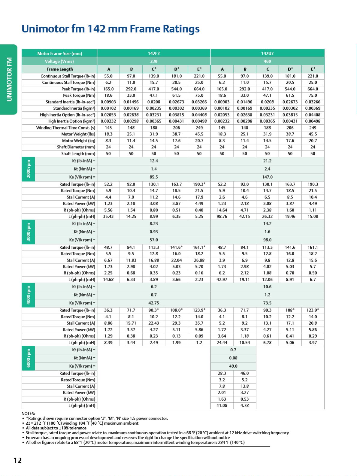
Unimotor
Motor
Frame
Voltage
Fram
Continuous Stall Torque (lb-in)
Continuous Stall Torque (Nm)
Standard Inertia (lb-in-sec') 0.00903 0.01496 0.0208 0.02673 0.03266 0.00903 0.01496 0.0208 0.02673 0.03266
Standard Inertia (kgm') 0.00102 0.00169 0.00235 0.00302 0.00369 0.00102 0.00169 0.00235 0.00302 0.00369
High Inertia Option (lb-in-sec') 0.02053 0.02638 0.03231 0.03815 0.04408 0.02053 0.02638 0.03231 0.03815 0.04408
High Inertia Option
Winding Thennal Time Const. (sl 145
I
.
-
-
-
I
I
NOTES:
• *Ratings shown require
212
"F
data
other
subject
(100
an
figures relate
• .6.t=
•
All
• Stall torque, rated
• Emerson has
All
•
fm
Size
(mm)
(Vrmsl
e l ength A B
Peak Torque (lb-in)
Peak Torque (Nm)
Motor Weight (lbs)
Motor Weight (kg)
ShaftOiameter(mml
Shaft
length
Kt
(lb-in/Al=
Kt(Nm/Al = 1.4
Ke
(V/k
Rated Torque (lb-in)
Rated Torque (Nm)
Stall Current
Rated Power
R (ph-ph) (Ohms)
L (ph-ph) (mH)
Kt
(lb-in/Al=
Kt(Nm/Al =
Ke
(V/k
Rated Torque (lb-in)
Rated Torque (Nm)
Stall Current
Rated Power
R (ph-ph) (Ohms)
L (ph-ph) (mH)
Kt
(lb-in/Al=
Kt(Nm/Al =
Ke
(V/k
Rated Torque (lb-in)
Rated Torque (Nm)
Stall Current
Rated Power
R (ph-ph) (Ohms)
L (ph-ph) (mH)
Kt
(lb-in/Al= 0.7
Kt(Nm/Al =
Ke
(V/k
Rated Torque (lb-in)
Rated Torque (Nm)
Stall Current
Rated Power
R (ph-ph) (Ohms)
L (ph-ph) (mH)
connector
·q
winding
to • 10
% tolerance
torque
and
ongoing process
to a 68
142
(kgm'l
(mm)
rpm)=
(A)
(kW)
rpm)=
(A)
(kW)
rpm)=
(A)
(kW)
rpm)=
(Al
(kW)
option "
104
"F
(40
power relate
of
development
'F (20 '
C)
mm
55.0 97.0
6.2
165.0
18.6
0.00232 0.00298 0.00365 0.00431 0.00498 0.00232 0.00298 0.00365 0.00431 0.00498
18.3
8.3
24
50 50
52.2 92.0 130.1 163.7
5.9
4.4
1.23
5.56
35.43
48.7 84.1
5.5 9.5
6.67
1.73
2.25
14.68
36.3
4.1 8.1
8.86 15.71
1.72
1.29
8.39
J'
, "M
", "N" size 1.5 power connector.
·q
maximum
to
maximum continuous operation
motor
temperature; maximum intermittent winding
Frame Ratings
142EJ 142U3
c•
139.0 181.0
11.0 15.7
292.0
33.0
148
25.1
11.4
24
10.4
7.9
2.18
1.54
14.25
11.83 16.88
2.98
0.68 0.35
6.33
71.7
3.37
0.38
3.44
ambient
and
reserves
417.0
47.1
188 206
31.9
14.5 17.6
24 24
50
12.4
85.5
14.7
11.2 14.6 17.9
3.08
0.80 0.
8.99 6.
8.23
0.93
57.0 98.0
113.3
12.8
4.02
3.89 3.66
6.2
0.7
42.75
90.3*
10.2 12.2 14.0
22.43
4.27
0.23
2.49
the
right
to
change
o•
221.0
20
.5
544.0 664.0
61
.5
38.7
50
190.3*
18
.5
3.87
51
35
141.6 * 161.1 *
16.0
22.04 26.88
5.03 5.70
0.23 0.16
108.0
* 123.9*
29.3
5.11 5.86
0.13 0.09
1.
99
tested
in a 68
the
'F (20 '
specification
temperature
E*
25.0
75.0
249
45.5
20.7
24
50
21.5
4.49
0.40
5.25 98.76
18.2
2.23
35.7
1.2
A B C
55.0 97.0
6.2
165.0
18.6
145
18.3
8.3
24
50 50
52.2 92.0 130.1 163.7
5.9
2.6
1.23
14.64
48.7 84.1
5.5 9.5
3.9
1.73
6.2
42.97
36.3
4.1 8.1
5.2 9.2 13.1 17.1
1.72
3.64
24.44
28.3
3.2
7.8
2.01
1.63
11.08
C)
ambient
without
notice
is
284
•
139.0 181.0
11.0 15.7
292.0
33.0
148
25.1
11.4
24
10.4
4.6
2.18
4.71
42.15
6.9
2.98
2.12
19.11
71.7
3.37
1.18
10.54
0.08
49.0
46.0
5.2
13.8
3.27
0.53
4.78
at
12
kHz drive switching frequency
'F (140 '
C)
417.0
47.1
188 206
31.9
14.5 17.6
24 24
21.2
2.4
147.0
14.7
6.5
3.08
2.38
26.32
14.2
1.6
113.3
12.8
9.8
4.02
1.08
12.06
10.6
1.2
73.5
90.3
10.2 12.2 14.0
4.27
0.61 0.41 0.29
6.78
50
,I
o•
221.0
20
.5
25.0
544.0 664.0
61
.5
75.0
249
38.7
50
18
8.5
3.87
1.60
19.46
141.6 161.1
16.0
12.8
5.03 5.7
0.70
8.
91
108* 123.9*
5.11 5.86
5.06
45.5
20.7
190.3
.5
21.5
10.4
4.49
1.11
15.08
18.2
15.6
0.50
6.7
20.8
3.97
E*
24
50
12
Page 15
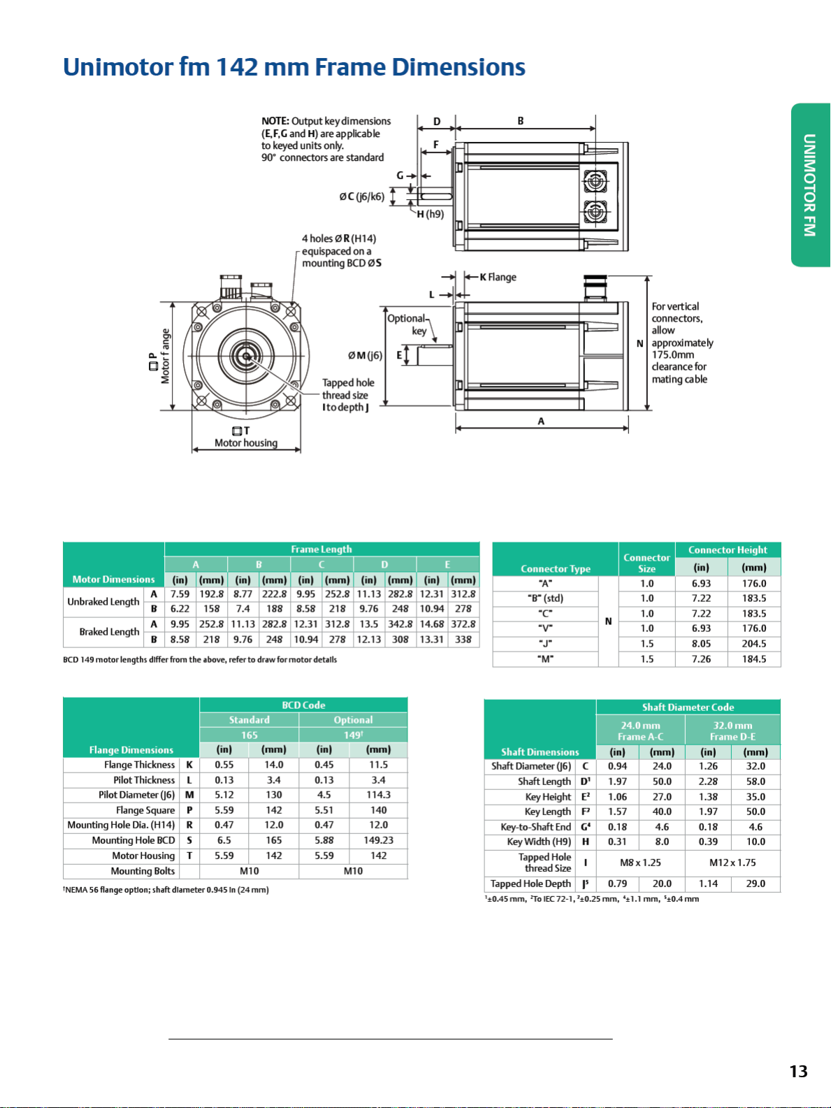
Unimotor
fm
142
CT
Motor
housln
mm
NOTE:
Output
(E,F,G
and
to
keyed
90°
connectors
Frame Dimensions
key
dimensions
H) areapplkable
units
only.
are
standard
4holes0R(H14)
equispaced
mounting
BCD
Tapped
thread
I
to
depth]
on
0M06
hole
size
a
0S
Optional\
)
El
key
I
0
lr-
L -l
KAange
B
tj
Forvertkal
I
~
'F=9
A
connectors,
allow
approximately
N
175.0mm
dearance
mat
Ing
for
cable
Unbraked Length
Braked Length
BCD
149 motor l
Flange Thickness K 0.55 14.0 0.45 11.5
Pilot Diameter 06) M 5.12 130 4.5 114.3
Mounting Hole
Mounting Hole
'NEMA 56 flange
A
B 6.22
A 9.95
B 8.58
engths
dtffer
Pilot Thickness
Flange Square
Dia.
(H14)
BCD
Motor Housing
Mounting Bolts
option;
shaft diameter
158
7.4 188
252.8 11.13 282.8
218 9.76 248
from
the
above,
refer to draw for motor
L 0.13 3.4 0.13
p
5.59 142 5.51
R 0.47 12.0 0.47 12.0
8.58
12.
31
10.94
s 6.5 165 5.88 149.23
T 5.59 142 5.59 142
Ml0
0.945
In
(24
mm)
218 9.76
312.8 13.5
278 12.13
detalls
Ml0
248 10.94 278
342.8 14.68 372.8
308
13.
31
3.4
140
338
1
±0.45
Connector
"A"
"B"
(std)
·c
·v·
•
J"
"M"
Shaft Dimensions
Shaft Length
Key
Height E'
Key
length
Key-to-Shaft
Key
Tapped Hole Depth
mm,
End
Width (H9) H
Tapped Hole
Size
thread
1To IEC 72-
Type
C
D'
p
G'
I'
1, 1±0.25
1.0 6.93 176.0
1.0 7.22 183.5
1.0 7.22 183.5
N
1.0 6.93 176.0
1.5 8.05 204.5
1.5 7.26 184.5
Shaft Diameter Code
24.0mm
FrameA-C
1.97 50.0
1.06 27.0
1.57 40.0
M8x 1.25
't 1.1
mm
4.6
, s±0.4
0.18
0.31 8.0
0.79 20.0
mm,
(inl (
32.0mm
FrameD-E
iEl
2.28 58.0
1.38
1.97 50.0
0.18
0.39 10.0
M12x1.75
1.14 29.0
mm
mml
35.0
4.6
13
Page 16
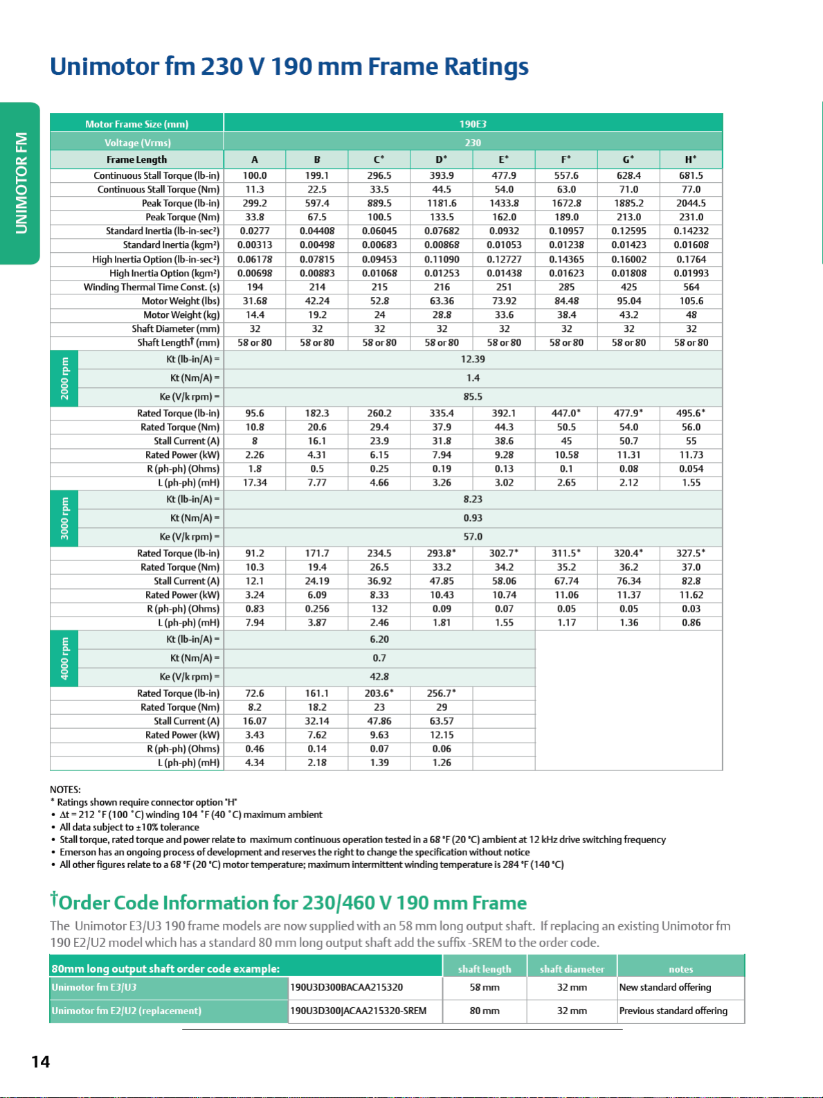
Unimotor
fm
230 V 190
mm
Frame Ratings
Motor Frame Size (
Voltage (Vrms
Fr
ame Length A B
Continuous Stall Torque (lb-in)
Continuous Stall Torque (Nm)
Standard Inertia (lb-in-sec') 0.0277 0.04408 0.06045 0.07682 0.0932 0.10957 0.12595 0.14232
Standard Inertia (kgm') 0.00313 0.00498 0.00683 0.00868 0.01053 0.01238 0.01423 0.01608
High Inertia Option (lb-in-sec') 0.06178 0.07815 0.09453 0.11090 0.12727 0.14365 0.16002 0.1764
High Inertia Option (kgm') 0.00698 0.00883 0.01068 0.01253 0.01438 0.01623 0.01808 0.01993
Winding Thermal Time Const. (s)
•
I:
§
'=
•
.
-
-
-
.
-
-
-
ii
mml
I 230
c•
100.0 199.1 296.5 393.9 477.9 557.6 628.4 681.5
To
rque (lb-in)
Peak
Peak Torque (Nm)
Motor Weight (lbs)
Motor Weight (kg)
Shaft Diameter (mm)
Shaft LengthT (mm)
Kt
(lb-in/A)= 12.39
Kt(Nm/A) = 1.4
Ke
(V/k
rpm)=
To
rque (lb-in)
Rated
Rated Torque (Nm)
Stall Current
Rated Power
R (ph-ph) (Ohms)
L (ph -ph) (mH)
Rated
Rated Torque (Nm)
Stall Current
Rated Power
R (ph-ph) (Ohms)
L (ph-ph) (mH)
Rated Torque (lb-in)
Rated Torque (Nm)
Stall Current
Rated Power
R (ph-ph) (Ohms)
L (ph-ph) (mH)
(kW)
Kt
(lb-in/A)= 8.23
Kt(Nm/A) = 0.93
Ke
(V/k
rpm)=
To
rque (lb-in)
(kW)
Kt
(lb-in/A)= 6.20
Kt(Nm/A) = 0.7
Ke
(V/k
rpm)=
(kW)
11.3 22.5 33.5 44.5 54.0 63.0 71.0 77.0
299.2 597.4 889.5 1181.6 1433.8 1672.8 1885.2 2044.5
33.8 67.5 100.5 133.5 162.0 189.0 213.0 231.0
194
31.68
14.4
32 32 32 32 32 32 32 32
58or80 58or80 58or80 58or80 58or80 58or80 58or80 58or80
95.6 182.3 260.2 335.4 392.1
10.8 20.6 29.4 37.9 44.3 50.5 54.0 56.0
(A)
(A)
(A)
8 16.1 23.9 31.8 38.6 45 50.7 55
2.26 4.31 6.15 7.94 9.28 10.58 11.31 11.73
1.8
17.34 7.77 4.66 3.26 3.02 2.65 2.12 1.55
91.2 171.7 234.5
10.3 19.4 26.5 33.2 34.2 35.2 36.2 37.0
12.1 24.19 36.92 47.85 58.06 67.74 76.34 82.8
3.24 6.09 8.33 10.43 10.74 11.06 11.37 11.62
0.83 0.256 132 0.09 0.07 0.05 0.05 0.03
7.94 3.87 2.46 1.81 1.55 1.17 1.36 0.86
72.6 161.1
8.2 18.2 23 29
16.07 32.14 47.86 63.57
3.43 7.62 9.63 12.15
0.46 0.14 0.07 0.06
4.34 2.18 1.39 1.26
214
42.24
19.2
0.5 0.25 0.19 0.13 0.1 0.08 0.054
215 216 251 285 425
52.8 63.36 73.92 84.48 95.04 105.6
24
42.8
203.6* 256.7*
190E3
o•
28.8
293.8* 302.7* 311.5* 320.4* 327.5*
85.5
57.0
E* F*
33.6
447.0* 477.9* 495.6*
38.4
(;*
43.2
H*
564
48
NOTES:
• Ratings shown require connector option "
•
at=212
.F(100 "()winding
All
data subject
•
• Stall torque, rated torque and power relate
• Emerson has an ongoing process
All
other
•
torder
The
Uni
190
E2/U2
80mm
Unimotorfm
-----------------
Uni
mot o rf
to
:t
figures relate
Code Information for
motor E3/
model which has a standard 80 mm long output shaft add
long
output
EJ/UJ 190U3D300BACAA215320
m E2/U2
(replacement)
104 "F(40 "
10%
tolerance
to a 68
'F (20 '
U3
190 frame models are now supplied with an 58 mm long output shaft.
shaft order code example:
14
H"
C)
maximum ambient
to
of
development and reserves
maximum continuous operation
C)
motor temperature; maximum intermittent winding temperature
the
right
to
change
tested
in a 68
the
specification without notice
230/460 V 190
the
190U3D300JACAA215320-SREM
'F (20 '
mm
suffix
C)
ambient
is
284 'F (140 '
Frame
-SREM
to
58mm
80mm
at
12
kHz
drive switching frequency
C)
If
replacing an existing
the
order code.
shaft
diameter
32mm
32mm
Uni
motor
fm
notes
New standard offering
Previous standard offering
Page 17
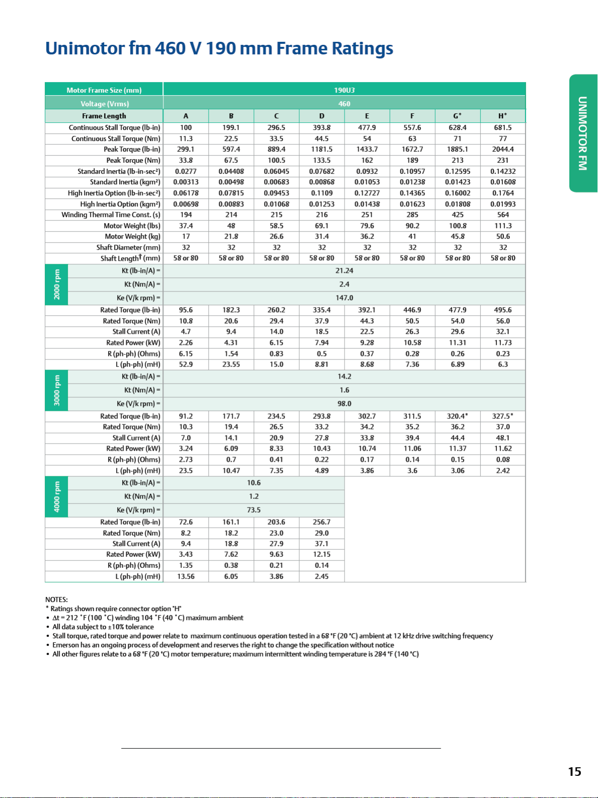
Unimotor
Motor
frame
Voltage (Vrms)
fr~me
Continuous Stall Torque (lb-in)
Continuous Stall Torque (Nm)
Standard Inertia (lb-in-sec') 0.0277 0.04408 0.06045 0.07682 0.0932 0.10957 0.12595 0.14232
Standard Inertia (kgm') 0.00313 0.00498 0.00683 0.00868 0.01053 0.01238 0.01423 0.01608
High Inertia Option (lb-in-sec') 0.06178 0.07815 0.09453 0.1109 0.12727 0.14365 0.16002 0.1764
High Inertia Option (kgm') 0.00698 0.00883 0.01068 0.01253 0.01438 0.01623 0.01808 0.01993
Winding Thermal Time Const. (s) 194 214 215 216 251 285 425 564
Shaft Diameter (mm)
.
-
-
-
.
-
-
-
I
fm
460 V 190
Size
(mm)
length
Peak Torque (lb-in) 299.1 597.4 889.4 1181.5 1433.7 1672.7 1885.1 2044.4
Peak Torque (Nm)
Motor Weight (lbs)
Motor Weight (kg)
Shaft
lengtht
(mm) 58
Kt
(lb-in/A) = 21.24
Kt(Nm/A) =
Ke
(V/k rpm) = 147.0
Rated Torque (lb-in) 95.6 182.3 260.2
Rated Torque (Nm)
Stall Current
Rated Power (kW)
R (ph-ph) (Ohms)
l (ph-ph) (mH)
Ke
Rated Torque (lb-in) 91.2 171.7 234.5 293.8 302.7 311.5
Rated Torque (Nm) 10.3
Stall Current
Rated Power (kW)
R (ph-ph) (Ohms)
l (ph-ph) (mH)
Ke
Rated Torque (lb-in) 72.6 161.1 203.6 256.7
Rated Torque (Nm) 8.2 18.2 23.0 29.0
Stall Current
Rated Power (kW)
R (ph-ph) (Ohms)
l (ph-ph) (mH)
(A)
Kt
(lb-in/A) = 14.2
Kt(Nm/A) = 1.6
(V/k rpm) = 98.0
(A)
Kt
(lb-in/A) =
Kt(Nm/A) = 1.2
(V/k rpm) = 73.5
(A)
A B C D E f
100
11.3 22.5 33.5 44.5
33.8
37.4
17
32
or
80
10.8
4.7 9.4
2.26 4.31 6.15 7.94 9.28 10.
6.15
52.9 23.55
7.0
3.24
2.73 0.7 0.41 0.22 0.17 0.14 0.15 0.08
23.5 10.47 7.35 4.89 3.86
9.4
3.43 7.62 9.63 12.15
35
1.
13.56 6.05 3.86 2.45
mm
199.1 296.5
67
.5 100.5 133.5 162
48
21.8 26.6 31.4 36.2 41 45.8 50.6
32 32 32 32 32 32 32
58
or
80
20.6 29.4
1.54
19.4
14.
1 20.9 27.8
6.09 8.33 10.43 10.74 11.06
10
18.8
0.
38
Frame Ratings
190U3
460
c;
•
393.8
58.5 69.1 79.6 90.2 100.8 111.3
58
or
80
58
or
80
335.4
37.9
14.0
0.83 0.5 0.37 0.28 0.26 0.23
15.0
26.5 33.2 34.2 35.2 36.2
.6
27.9 37.1
0.21 0.14
18
.5 22.5 26.3 29.6 32.1
8.81 8.68 7.36 6.89 6.3
477.9 557.6 628.4 681.5
54
58
or
80
2.4
392.1 446.9 477.9 495.6
44.3 50.5 54.0 56.0
33.8 39.4
58
63
189
or
3.6
58
80
58
320.4* 327.5*
71
213 231
or
80
11
.31 11.73
44.4
11.37
3.06 2.42
H*
77
58or80
37.0
48.
1
11.62
NOTES:
• Ratings shown require connector option "H"
.6.t
=212
·r(
100 "
()win
ding 104
"f(40
•
All
data subject
•
• Stall torque, rated torque
• Emerson has an ongoing process
All
other
•
to • 10%
figures relate
tolerance
an
d power relate
to a 68
'F (20 '
·q maximum ambient
of
development and reserves
C)
motor temperature; maximum intermittent winding temperature
to
maximum continuous operation
the
right
to
change
tested
in a 68
the
'f (20 '
specification without notice
C)
ambient
at
12
kHz
drive switching frequency
is
284
'f
(140 '
C)
15
Page 18
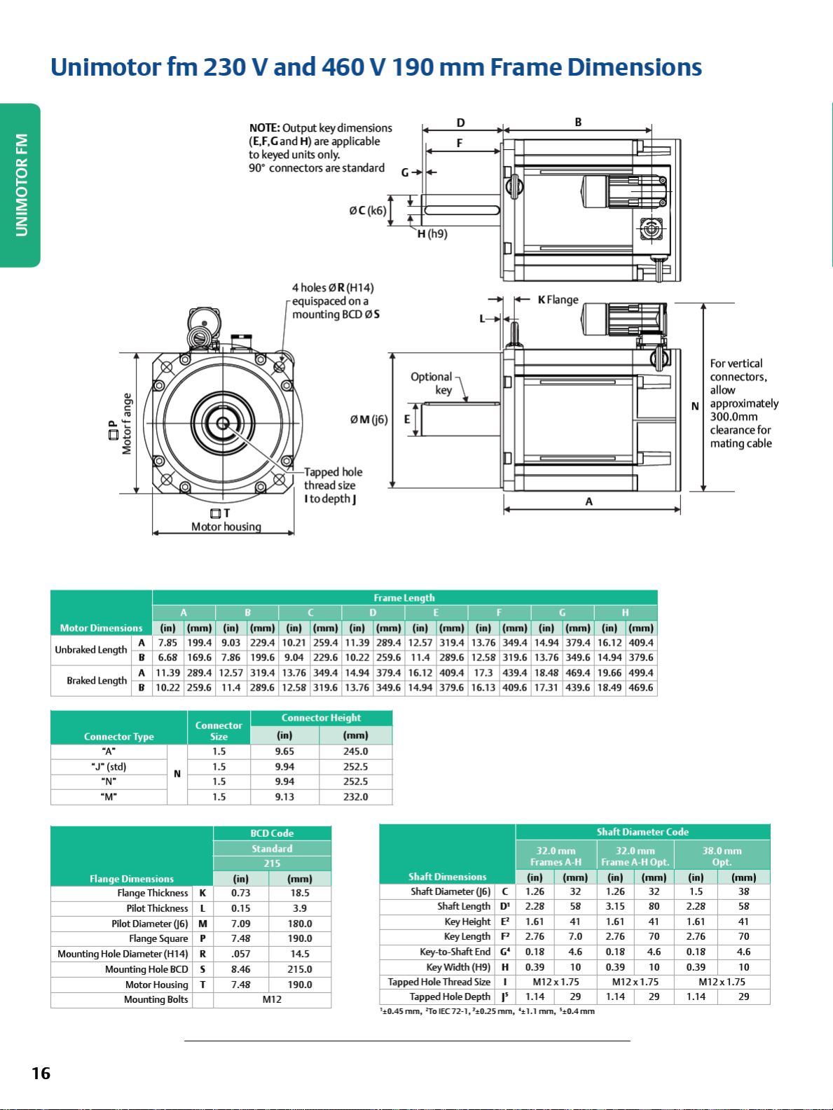
Unimotor
fm
230
V and
460 V 190
mm
Frame Dimensions
ci.'-
□
QJ
en
C:
ro
B
0
:E
lbll
T
Motor housin
NOTI:
Output
(E,F,Gand
to
keyed units only.
90° connectors are standard
key dimension
H) are applicable
0C(k6)
4holes0
equispaced
mounting
R(H14)
on
BCD
0MQ6)
Tapped hole
thread size
to
depth
I
J
a
0S
s
G
➔
I+-
TT
' H (h9)
Optional
E
key
KFlange
B
~I
II
i--,
11-
.
.
I -
•
lRIIP
For vertical
connectors,
D
F
-
ij
~
J
-
allow
N approximately
300.0mm
clearance for
mating cable
A
Unbraked Length
Braked Length
•
J"
Flange Dimensions
Mounting Hole Diameter (Hl 4) R .057 14.5
A 7.85 199.4 9.03 229.4 10.21 259.4
B 6.68 169.6 7.86 199.6 9.04 229.6 10.22 259.6 11.4 289.6 12.58
A 11.39 289.4 12.57 319.4 13.76 349.4 14.94 379.4 16.12 409.4 17.3
B 10.22 259.6 11.4 289.6
"A"
(std)
"N"
"M"
Range Thickness
Pilot Thickness L 0.15 3.9
Pilot Diameter 06)
Flange Square
Mounting Hole
Motor Housing T 7.48 190.0
Mounting Bolts
BCD
1.5 9.65 245.0
1.5 9.94 252.5
N
1.5 9.94 252.5
1.5 9.13 232.0
K
M 7.09 180.0
p
7.48 190.0
s 8.46 215.0
12
.58 319.6 13.76 349.6 14.
(i
nl (mml
BCD
Code
Standard
215
M12
11.39
289.4 12.57 319.4 13.76
94
Shaft Dimensions
Shaft Diameter 06)
Key-to-Shaft
Hole
Tapped
Tapped
1
:t0.45 mm, 2To I
379.6 16.13
Shaft Length
Key
Height
Key
length
Key
Width
Thread
Hole
EC 72-
349.4 14.94 379.4
319.6 13.76 349.6
439.4 18.48 469.4
409.6 17.31 439.6
32.0
Frames
16.12 409.4
14.94 379.6
19.66 499.4
18.49 469.6
Shaft Diameter Code
mm
A-H
Frame
32.0
mm
A-H
Opt. Opt.
lmlllllllnlll-llllllDII
C
0'
2.28 58 3.15 80 2.28 58
E2
1.61
p
2.76 7.0 2.76 70 2.76 70
c;•
End
(H9)
Size
Depth
1, 1±0.25
0.18
H 0.39 10 0.39 10 0.39 10
1.14 29 1.14 29 1.14 29
I'
mm,
':t
1.1
41
1.61
41
4.6
0.18 4.6 0.18 4.6
M12x1.75 M12x1.75 M12x 1.75
mm, 5:t0.4
mm
IIE
1.61
38.0
mm
EIII
41
16
Page 19

UNIMOTOR FM
17
Page 20

Unimotor
Motor
Frame
Size (
Voltage (Vrmsl
Frame Length D E F
Continuous Stall Torque (lb-in)
Continuous Stall Torque (Nm)
Peak Torque (lb-in)
Standard Inertia (lb-in-sec') 0.243 0.298 0.354
Standard Inertia (kgm') 0.028 0.034
High Inertia (lb-in-sec') 0.361 0.444 0.528
High Inertia (kgm') 0.041 0.050 0.060
Winding Thermal Time Const. (s)
Motor Weight (lbs)
Motor Weight (kg)
Shaft Diameter (mm)
Shaft Length (mm)
I
Ell
.
-
-
-
I:
~
~
Rated Torque (lb-in)
Rated Torque (Nm)
Rated Torque (lb-in)
Rated Torque (Nm)
Rated Torque (lb-in)
Rated Torque (Nm)
I
ml
NOTES:
• i!.t= 212
•
• Stall torque, rated
• Emerson has
•
All
All
data
other
subject
·F
figures relate
Rated Torque (lb-in)
Rated Torque (Nm)
(100 ·
CJ
winding
to
:t
10%
torque
an
ongoing process
fm
250
mml
Peak Torque (Nm)
Kt
(lb-in/A)=
Kt(Nm/A) =
Ke
(V/k
rpm)=
Stall Current
Rated Power
R (ph-ph) (Ohms)
Stall Current
Rated Power
R (ph-ph) (Ohms)
Stall Current
Rated Power
R (ph-ph) (Ohms)
Stall Current
Rated Power
R (ph-ph) (Ohms)
to a 68
(kW)
L (ph-ph) (mH)
Kt
(lb-in/A)=
Kt(Nm/A) =
Ke
(V/k
rpm)=
(kW)
L (ph-ph) (mH)
Kt
(lb-in/A)=
Kt(Nm/A) =
Ke
(V/k
rpm)=
(kW)
L (ph-ph) (mH)
Kt
(lb-in/A)=
Kt(Nm/A) = 2.1
Ke
(V/k
rpm)=
(kW)
L (ph-ph) (mH)
104
· F (40
tolerance
and
power relate
of
'F (20 '
mm
814
92
2443
276
439 486
126.5
57.5 65.5
48 48 48
110 110 110
664
75
(A)
17.2
7.9
0.61 0.48 0.34
22.9
593
67 76
(A)
25.8
10.5 11.9 13.2
0.27 0.21 0.15
10.0
593
67
(A)
34.4
10.2 11.5 12.7
0.15 0.10 0.08
5.7
549
62 70
(A)
43
9.7
0.09 0.08 0.06
3.5
·CJ
maximum
to
development
CJ
motor
Frame Ratings
250UJ
460
1027 1204
116 136
3080
348
144.1 162.1
47.8
5.4
323
814
92
21.7 25.4
9.6
19.1
31.9
3.6
216
673 743
32.5
8.6
23.9
2.7
162
655 717
74
43.4
4.2
18.6
129
620
54.2 63.6
11
3.1
ambient
maximum continuous operation
and
reserves
temperature; maximum
the
3611
408
0.04
608
73.7
938
106
11.1
14.9
84
38.1
6.6
81
50.9
3.7
681
77
12.1
2.6
right
to
intermittent
change
tested
the
in a 68
specification
winding
'F (20 '
CJ
ambient
without
temperature
is
at
12
kHz drive switching frequency
notice
284
'F
(140
'CJ
18
Page 21

Unimotor
fm
250
mm
Frame Dimensions
..
□
□ P
T
APPED
I
(,J)
t-Kl
l.E
~
G_
~
lr
n
-
F
-
~~
..., K
D
((Q))
B
.....
....
A
A1
,.1
~
((Q))
\
,?
-
IWII
~
~
-
r-
1
9
g
A
Unbraked Length Al 24.8 630.1
B 7.07 179.7
A 17.42 442.5
Braked Length
Mounting Hole Diameter (H14) R
NOTE:
Al 27.6 701.9
B 9.90 251.5
Flange Dimensions
Pilot Thickness
Pilot Diameter 06)
Flange Square
Mounting Hole
Motor Housing T
Terminal
Mounting
Shaft options below
BCD
Box Wid
Bolts
th
the
25.9 660.1
8.26 209.7
18.60 472.5
28.8 731.9
11.08 281.5
K
0.18 4.50
L
9.84 250.0
M
p
10.08 256.0
0.73 18.5
s
11.81 300.0
9.82 249.5
u
7.32 186.0
standard (Std) dimensions
27.2 690.1
9.44 239.7
19.78 502.5
30.0 761.9
12.26 311.5
BCD
Code
Standard
215
M16
Tapped Hole Thread Size M12x1.75mm
1
:t0.4Smm, ?Jo1EC72-1,1:1:
will
require
'V"
·c
"B"
"
H"
(std)
Shaft Diameter 06) C
Shaft Length
Key
Height
Key
length
Key-to
-Shaft
Key
Width (H9) H 0.39 10.0
Tapped Hole Depth
customer
approval
11.48 291.5
12.30 312.5
12.30 312.5
14.3 363.5
D' 3.15 80.0
E'
1.61 41.0
p
2.76 70.0
End
G'
0.18 4.6
1.46 37.0
I'
0.2Smm,
'±1.1
and
may
not
mm, s±0.4mm
be
covered by warranty.
8.70 221
8.70 221
8.70 221
8.70 221
4.33 110.0
1.77
3.94 100.0
0.24 6.0
0.47
1.46
45.0
M16x2.0mm
37.0
12.0
4.33 110.0
2.03 51.5
3.94 100.0
0.24 6.0
0.55 14.0
M16x2.0mm
1.14 29.0
19
Page 22

Unimotor
fm
E3/U3 Power Connector Size Reference Tables
Unimotor
Use
This
with a size
23
0 V - 75 to 142
-
2000(rpm)
3000(rpm)
4000(rpm)
6000(rpm)
Power Connector code above~.
460
V - 75 to 142
2000(rpm)
3000(rpm)
4000(rpm)
6000(rpm)
Power Connector code above~.
23
0 V - 190
the
tables
motor
mm
fm E3/U3 Pow
below
to
example
1.5
~~~~~~~~-~~~~-~~~~-
has
connector.
mm
Frames
075EJ 095EJ
1.0 1.0 1.0 1.0 1.0 1.0 1.0 1.0 1.0 1.0 1.0 1.0 1.0 1.0 1.0 1.0 1.0 1.0 1.5
1.0 1.0 1.0 1.0 1.0 1.0 1.0 1.0 1.0 1.0 1.0 1.0 1.0 H 1.0 1.0 1.0 1.5 1.5
1.0 1.0 1.0 1.0 1.0 1.0 1.0 1.0 1.0 1.0 1.0 1.0 H H 1.0 1.0 1.5 1.5 1.5
1.0 1.0 1.0 1.0 1.0 1.0 1.0 1.0 1.0 1.0 1.0
mm
Frames
1.0 1.0 1.0 1.0 1.0 1.0 1.0 1.0 1.0 1.0 1.0 1.0 1.0 1.0 1.0 1.0 1.0 1.0 1.0
1.0 1.0 1.0 1.0 1.0 1.0 1.0 1.0 1.0 1.0 1.0 1.0 1.0 1.0 1.0 1.0 1.0 1.0 1.0
1.0 1.0 1.0 1.0 1.0 1.0 1.0 1.0 1.0 1.0 1.0 1.0 1.0 1.0 1.0 1.0 1.0 1.0 1.5
1.0 1.0 1.0 1.0 1.0 1.0 1.0
Frames
er
Connector
indentify
power
the
connector
example:
C,
V
=Size
1.0 and J, M, N
75UJ 95UJ
C,
V
=Size
1.0 and J, M, N
190EJ
size
reference tables
standard
connection
order
O(J_tion J (size
142E3400JACAA
=Size
1.5, H =terminal
=Size
1.5, H =terminal
type
provided
1.5)
165240
box
box
for
the
and
requires a motor
different
115EJ 142EJ
115UJ
frame
power
sizes.
cable
142UJ
2000 (rpm) 1.5 1.5 1.5 1.5
3000 (rpm) 1.5 1.5 1.5 1.5
4000 (rpm) 1.5 1.5 H H
J, M, N
=Size
Power Connector code
460
V - 190
mm
Frames
.
'I
2000(rpm)
3000(rpm)
4000(rpm)
Power Connector code
1.5 1.5 1.5 1.5 1.5 1.5 1.5 1.5
1.5 1.5 1.5 1.5
1.5 1.5 1.5 1.5
J, M, N
1.5, H =terminal
=Size
1.5, H =terminal
box
190UJ
box
20
Page 23

UNIMOTOR FM
21
Page 24

UNIMOTOR FM
Unimotor fm Motor Selection Considerations
Feedback
SinCos Cycles
Feedback Device
Order Code Feedback Type
AE Resolver
CA Incremental Encoder 5 Vdc 4096 16384 (14 bit) +/- 60 arc second
EC (Multi-turn)
FC (Single-turn) (19 bits)
RA (Multi-turn)
SA (Single-turn) (20 bits)
EB (Multi-turn)
FB (Single-turn) (21 bits)
NOTES:
1
Resolution value shown when used with the Unidrive M resolver input or SM-Resolver Option Module (Unidrive SP and Digitax ST)
2
Resolution value shown when used with the Unidrive M, Unidrive SP or Digitax ST when the encoder type is set to either SC EnDat or
SC Hiper, depending on the encoder. Multi-turn devices have 4096 (12 bit) resolution.
Absolute Encoder EnDat
SinCos Encoder HIPERFACE
Absolute Encoder EnDat
1
Inductive
Optical
Optical
Encoder Supply
Voltage
6 Vrms
Excitation 6 kHz
2
2
2
5 Vdc 32
7 - 12 Vdc 1024
3.6 - 14 Vdc 2048
or Incremental
Pulses per
Revolution
075-250 motors
1 16384 (14 bit) +/- 720 arc second
Resolution Available to
Position Loop Feedback Accuracy
Medium Medium
Medium High
HIgh Medium
Absolute position
524288
Very high High
6
1.04 x 10
Very High Very High
6
2.08 x 10
+/- 280 arc second
+/-52 arc second
+/-20 arc second
(Differential non linearity +/- 1% signal period)
22
Page 25

Motor
Selection Considerations
Motor
Motor
Any
performance
temperature
drive switching frequency
Selection
Derating
adverse operating conditions require
be
derated. These conditions include
above
104
°F
(40 °C),
or
motor
a drive oversized for
that
the
motor
mounting position,
the
Ambient Temperatures
For
ambient
must
applies
be
derated
to
motors up
temperatures
using
the
to
3000
above
104
°F
(40 °
C),
the
following formula as a guideline (only
rpm
and
assumes
copper
dominate).
New
derated
Specified
· Measured In
For example, with
new
derated
Drive Switching Frequency
Most drive current ratings
torque=
torque
•c
torque
X
✓,-1-_
an
....,.
a=-a-m
...,.
b-ie-nt-t-em_p_er_a_tu-re-•-_-4-01
ambient
will
temperature
be
0.8 x specified
are
reduced
-:-/,-1-0--,
of
169 °F (
torque
.
at
higher switching
frequencies. See individual drive manuals for details.
motor
Most
current
frequencies. See
(these
figures
ratings
are
the
table
below for
are
for guidance only).
reduced
motor
at
lower switching
derating factors
ambient
motor.
torque
losses
0)
76
°C),
the
Thermal Protection
Thermistor protection
to
293
°F
windings and gives an indication
The installer
to
do
out.
DJJJ.S1
so
will invalidate
connect
the
the
motor
Environmental Conditions
Any
liquids
or
gases
that
may
come
be
must
confirmed
to
ensure
compliance with
international standards.
Brake Operation
Do
not apply
brake can only
operations
the
take
and
brake while
a limited number
must not
be
the
used for repeated dynamic braking.
Thermal Test Conditions
In
general,
mounting surface
gearbox,
the
Thermal
motor
motor
the
motor
is
mounted
motor
torque
is
heated
is
connected
in
mounting
should
from
a confined space with restricted air flow.
arrangement
(145 •q
is
built into
of
serious overheating problems.
thermistor
warranty
into
contact
motor
shaft
of
emergency braking
be
derated
an
external source such
to a poor
test
the
to
the
drive. Failure
if
winding burns
with
the
correct
is
rotating. The
if
the
motor
thermal
conductor, or
example:
motor
the
motor
as
a
Ingress Protection
IP65 conformance; sealed against
and
Hz
frame
75
95
(E-H)
connected
fm
Motor
0.93 0.88 0.89 0.84 0.87
0.94
0.
kHz
fm
Motor
DJ
mounted
Uni
motor
3 kHz
4k
5/6 kHz 0.95 0.93 0.93
8kHz
1
0/12/16
Uni
motor
Motor
Size
(
mml
115
142
190 (A190
250
.
Derating Factors
0.91 0.91
98
0.97 0.97 0.95 0.97 0.96 0.
Holding Brake Specifications
Powe
r Supply
(V
dcl (WI (lb-inl (Nml (m
24
24
24
24
24
24
24
Power
water
spray
and
dust
0.81
0.87
0.91
0.86 0.99 0.55
0.90 0.94 0.89 0.99
Inpu
t
Static Tor
que
6.3
16
23
23
25
25
62
19.5
108
177
177
221
548
1
195
0.98
2.2
1
2.2
20
20
42
67
135
when
0.88
0.90
0.77
0.
94
90
0.
98
Mechanical
Release Time Added Inertia Added Wei
sl
(lb-in-sec2 I ( kgcm21 (lbl (kgl
22
60
120
120
95
120
250
0.
00006
0.
00035
0.
00039
0.
00048
0.
00035
0.
00035
0.01452
075-095
115-142 13.
190
0.07
0.39
0.24
0.3
0.39
0.39
1
6.4
19.7x19.7x0.8
T
Alum
mum
Heatsmk
(inl
9.8
X 9.8 X 0.6
8x13.8x0.8
ght
1.1
0.5
1.3 0.6 0.
2.6
1.2 0.75
3.7
1.7 0.75
4.4
2.0 0.77
4.4
2.0 0.77
24.2 11.0
Plate
(mml
250x
250 X 15
350x350x20
500x500x20
Oegress
n
1.03
94
0.5
NOTES:
• Figures shown in individual
• App
ly a derate
• Backlash will
factor of 0.7
increase
over time
motor
to
standard br
sections
are
ake
at
68
torque
'F (20 '
CJ
ambient
figures if motor
temperature
is above
212
'F
(100
'CJ
23
Page 26

Unimotor
hd
230 V I
460
V
Compact, Powerful High Dynamic
AC
Servo
Designed for maximum
brushless
compact,
torque
high
Unimotor hd
absolute
nameplate"
can
be
read by
used
to
simplifies commissioning
performance
Motors
torque
density,
AC
Servo
motor
series provides an exceptionally
low inertia solution for applications
during rapid acceleration and deceleration profiles.
motors
fitted with high resolution SinCos
encoders
automatically optimize
data
most
and
are
pre-loaded with
during
the
manufacturing process. This
Control Techniques' brand servo drives
the
and
maintenance, ensures consistent
saves time.
the
Unimotor
that
require very
the
motor
"electronic
drive settings. This feature
hd
or
data
and
Unimotor
clll1P
The Unimotor
Digitax
maximum dynamic performance.
Key Features
• Torque range:
• High torque-to-inertia ratio for high-dynamic performance
Compact
•
• Optional holding brake
• IP65 conformance
•
Segmented
• World class performance
• Winding
Speeds
•
• Large shafts
• Multiple feedback options:
- Incremental encoder: High accuracy, medium resolution
- Absolute: Medium accuracy,
and
- SinCos/absolute: High accuracy, high resolution,
single-turn
-
HIPERFACE
supported
- Resolver: Robust for
lower accuracy, medium resolution
hd
torque
profile
ST
Servo drives providing
6.4
to
752 lb-in (0.72
and powerful
stator
design
to
suit
230
V and
include
multi-turn
2000,
3000,
to
increase torsional rigidity
and
multi-turn
(SICK)
and
is
closely matched
up
to
300%
to
85.0
460
V
4000
and
6000
medium
EnDat (Heidenhain) protocols
extreme
applications
to
peak
overload for
Nm)
rpm
resolution, single-turn
and
conditions;
Unimotor
Frame
Si
ze
ss
67
89
11
S
1
42
190
-
hd
motors
Unimotor
Contln
uous(lb-ln) -
(shown
10
with a Digitax
ST
Servo
hd Torque Range
100
Pea
k(lb-ln)
drive).
1000
Approvals
24
FM30610
RoHS
Compliant
All
Unimotor
connections
easier
cable
installation.
hd
motors
that
rotate
routing
feature
for
and
Page 27

Unimotor
hd
230 V I
Order Code information
Use
the
information below
to
create
an
order
460
code
for a
V
Uni
motor
hd
(top
row
is
an
example).
l!ID
■
•I•
■
-----
Stator
Frame
>-->-->---
>---
Motor
Siz
e Voltage
ID=
055
UD=4
06
7
089
115
142
190
NOTES:
*Halfke
yp
*
*Holding
!Refer to 142 mm Frame
T
Add
Bolt
(11
and 14 mm are standard). ex.
Length
055-089 055-067 055-190 055-115
Frames Frames Frames Frames
230V
60V
115
142
190
rovided
brakes are not designed
Grde
Diameter
Speed
A
30=
3000 rpm
60=
B
C
Frame
B
C
D
Frame
C
D
E
Frame
C
D
F
to
create a smooth shaft and balance
6000 rpm
089Frame
30=
3000 rpm
40=
4000rpm
60=
6000 rpm
115
Frame
20=
2000 rpm
30=
3000 rpm
142
Frame
10=
1000 rpm
15
= 1500 rpm
20=
2000 rpm
30=
3000 rpm
190
Frame
10=
1000 rpm
15
= 1500 rpm
20=
2000 rpm
for
Ratings
and Dimensions table for commector size data
(BCD)
and Shaft Diameter code
055EDC600BACRA
Brake Connection
(MV)
0=Not
Fitted
5
=
Brake
dynamic use
Holding
..
063110
Ty
pe
B = Power size
1.0 and
90' and w/full
Rotatable installed
142 Framel
B = Power size
1.0 and
90' and
Rotatable
Signal
Signal
Output
Shaft
A =
Keyway
F=
Keyway
w/full&
half key•
provided
I = Power size
Signal
1.5 and
90' Rotatable
190 Frame
I = Power size
1.5 and
90'
signal
Rotatable
and
for
055 frame only
Feedback Device
CR= Incremental Encoder
(Renco)
..
key
EM=
SinCos
Multi-Tum
FM = SinCos
AR=
CR=
(Renco)
EM=
FM=
AR= Resolver
CA=
(SICK)
EC=
EB=
FB
FC = SinCos
RA=
SA=
AE
Single-Tum
Resolver
Incremental
..
SinCos
Multi-Tum
SinCos
Single-Tum ECI 1118-EnDat
089 -190
Incremental Encoder
SinCos Muti-Tum
SinCos
Multi-Tum
=
SinCos
Single-Tum
Sinqle-Tum ECI 1319-EnDat
SinCos
Multi-Tum
SinCos
Single-Tum
= Resolver
055Frame
67Frame
Encoder
Fram
4096 ppr
(R35i)
EQI
1130 -
EO
1118-EnDat
4096 ppr
(R35i)
EQI
1130 -
es
(CFS50)
4096 ppr
EQI
1331 -EnDat
EQN
1325 -
ECN
1313 -
SRM
50
(GEN
-HIPERFACE
SRS
50
(GEN
-HIPERFACE
11114\111.'i!N
BCD
Inertia
1
A = Std. I 063
EnDat
EnDat
EnDat
EnDat
2)
2)
Diameter
055 Frame
9.0A-C
11.0A-C
14.0A-C
Shaft
OnlyT
The
Unimotor
the
capabilities
hd
series
of
Emerson
servo
Industrial
motor
Automation motion systems that
high
torque
in
a small
size
as
well
for
incremental
and
resolver
encoders,
motor
absolute
feedback.
expands
provide
as
support
encoders
25
Page 28

Unimotor
Motor
Frame Size
Voltage (Vrms I
Fr
ame l ength A B C A B
Continuous Stall Torque (lb-in)
Continuous Stall Torque (Nm) 0.72
Peak Torque (lb-in)
Motor Weight (kg) 1.2 1.5
n
~
Iii
Rated Torque (lb-in)
Rated Torque (Nm) 0.7 1.05 1.48 0.7 1.05
n
~
a
Rated Torque (lb-in)
Rated Torque (Nm) 0.68 0.9
hd
(mml
Peak Torque (Nm) 2.88 4.72 6.6 2.88 4.72
Inertia (lb-in-sec') 0.00012 0.00022 0.00032 0.00012 0.00022
Inertia (kgm2) 0.000014 0.000025 0.000036 0.000014 0.000025
Motor Weight (lb)
of
Number
Kt(lb-in/A) = 6.55 7.7 8.05 6.55
Kt(Nm/A) = 0.74 0.87
Ke
(V/k
rpm)=
Stall Current
Rated Power (hp) 0.29 0.44 0.62 0.29 0.44
Rated Power (kW)
R (ph-ph) (Ohms)
l (ph-phl (mH) 50.0
Kt(lb-in/A) =
Kt(Nm/A) = 0.45 0.43 0.48
Ke
(V/k
rpm)=
Stall Current
Rated Power (hp) 0.58 0.76 1.01 0.58 0.76
Rated Power (kW)
R (ph-ph) (Ohms)
l (ph-ph) (mH)
55
mm
6.37 10.44 14.6 6.37
25.49 41.78 58.42 25.49
2.64
Poles 8 8 8 8 8
45
6.2 9.29 13.1 6.2 9.29
(A)
0.97 1.36 1.81 0.97 0.79
0.22 0.33 0.46 0.22 0.33
28.0 14.12 9.53 28.0
3.98
27 26 29
6.02 7.97 10.62 6.02 7.97
(A)
1.61
0.43 0.57 0.75 0.43 0.57
8.50
16.00
Frame Ratings and Dimensions
OSSEO
1.18
3.3
52.5 55
32.00
3.81 4.25
2.74
3.55
8.20
1.65 0.72
3.96
0.91 0.74
23.0 50.0 100.0
3.44
2.38 28.00 10.70
6.30 50.00 25.00
1.8
1.2
2.64
1.2 1.5
45
6.55 6.99
0.74
45
0.68 0.9
0.97
,
10.44
1.18
41.78
3.3
13.19
1.49
45.0
0.79
47.5
1.49
90
'I
C
14.6
1.65
58.42
6.6
0.00032
0.000036
3.96
1.8
8
14.6
1.65
100
13.1
1.48
1
0.62
0.46
31.0
75.0
7.35
0.83
50
10.62
1.2
1.99
1.01
0.75
7.80
20.00
4 holes
0R
hole
depth I
(H14)
BCD
0S
equispaced on a
mounting
~}
I
Tapped
i...i
-.::..--
-~-
--'~"'
thread size
I
[JIT
D
K
H
to
B
A
Shaft
Shaft Diameter
Key-to-Shaft End
Tapped Hole Thread Size
Tapped Hole Depth
26
9.0mm
Dimensions
06)
C
0 0.790 20.0 0.906 23.0 1.181
Key
Height E 0.402 10.2 0.492 12.5
Key
length
F 0.591 15.0 0.591 15.0
c;
0.039 1.0 0.059 1.5
Key
Width (H9)
H 0.118
0.394 10.0 0.531 13.5
3.0
M4x10 M4x10
Shaft
Diameter
11.0mm 14.0mm
0.157 4.0
Code
0.629
0.886
0.142
0.197
0.492
30.0
16.0
22.0
M5x12.5
12.5
3.6
5.0
Unbraked
Braked
Mounting Hole Diameter(H14)
B
A 6.22
length
B 5.12 130 6.06 154 7.01
Mounting Hole
Terminal
A
length
3.55
90
158
Range Thickness
Pilot Thickness
Pilot Diameter 06)
Range Square
BCD
Motor Housing
Box
Width
Mounting
Bolts
4.49
114
5.43
7.17 182 8.11
K 0.276
l 0.098
M 1.584
N
3.897
p
2.165
R 0.228
s 2.480
T 2.115
MS
138
206
178
7.0
2.5
40.0
99.0
55.0
5.8
63.0
55.0
Page 29

Unimotor
hd
67
mm
Frame Ratings and Dimensions
Motor
Frame Size
Voltage
Fram
Continuous Stall Torque (lb-in) 12.8 22.6
Continuous Stall Torque (Nm)
Peak Torque (lb-in)
Motor Weight (kg)
.
-
-
Iii
Rated Torque (lb-in)
Rated Torque (Nm)
.
!:'
>;
-
,i,
Rated Torque (lb-in)
Rated Torque (Nm)
NOTES:
•
.6.t=
212 'F (100 '
tolerance
• Stall torque, rated torque and power relate
'F (20 '
CJ
• Maximum intermittent winding
ambient
(mml
(Vrmsl
e length A B C A B C
Peak Torque (Nm)
Inertia (lb-in-sec')
Inertia (kgm') 0.000030 0.000053 0.000075 0.000030 0.000053 0.000075
Motor Weight (lb)
Number
of
Kt
(lb-in/A)= 8.23 7.08
Kt(Nm/A) = 0.93 0.80
Ke
(V/k
Stall Current
Rated Power (hp)
Rated Power
R (ph-ph) (Ohms)
L (ph-ph) (mH)
Kt
(lb-in/A)= 4.16 7.08
Kt(Nm/A) = 0.47 0.80
Ke (V/k
Stall Current
Rated Power (hp)
Rated Power
R (ph-ph) (Ohms)
L (ph-ph) (mH)
CJ
winding 104 ' F (40 '
above
0.00027 0.00047 0.00066 0.00027 0.00047 0.00066
Poles
rpm)=
(A)
(kW)
14.92
45.43 17.40 12.70
rpm)=
(A)
(kW)
11.06 4.35
12
kHz drive switching frequency
temperature
067ED
1.45 2.55
38.5
4.35 7.65 11.10 4.35 7.65 11.10
4.40 5.72 7.04 4.41 5.73 7.05
2.00 2.60
10
12.4 21.7
1.40 2.45
1.56
0.59 1.03 1.48 0.59 1.03 1.48
0.44 0.77 1.10 0.44 0.77 1
28.5
11.5 19.5 11.5 19.5 27.4
1.30 2.20
3.12
1.10 1.85
0.82 1.38 0.82 1.38 1.95
3.86
CJ
maximum ambient;
to
32.7
3.70
67.7 98.2
3.20
10
57.0
31.0
3.50
2.74
4.88
5.48
1.22 11.69
3.98 1.81 1.59 2.31
3.33
maximum continuous operation
is
284
'F
(140
12.8
1.45 2.55
38.5
2.00 2.60
10
10
49.0
12.4
1.40
11.69 15.20 10.70
35.18
1.30
1.81
1.10
35.18
all
data
subject
'
CJ
I ,
• , I
22.5 32.7
3.70
67.7 98.2
3.20
10
21.7
2.45
54.20 40.80
49.0
2.20
3.19
1.85 2.61
3.79
13.60 10.20
to
tested
14.16
1.60
98.0
..
/-10%
in
10
31.0
3.50
.10
3.10
4.63
2.68
a
68
OP
0
~)).
~Tapped
OT thread
Shaft Diameter C 0.551
Shaft Length
Key
Height E 0.629
Key
Length F
Key-to-Shaft
Key
Width
Tapped Hole Thread Size
Tapped Hole Depth
4 holes
equispaced on a
mounting
I
I to depth I
D 1.181
End
G 0.142
H 0.197
0R
(Hl
4}
BCD
0S
hole
size
0.964
M5x0.8
0.53 13.5
14.0
30.0
16.0
25.0
3.6
5.0
Unbraked Length
Braked Length
A 5.62 142.7 6.80 172.7 7.98 202.7
B 4.28 108.8 5.46 138.8 6.65 168.8
A 7.00 177.7 8.18 207.7 9.37 237.7
B 5.66 143.8 6.84 173.8
8.02
203.8
Flange Thickness
Pilot Thickness
Pilot Diameter
Overall Height
Flange Square
Mounting Hole Diameter
Mounting Hole
Motor Housing
Mounting Bolts
BCD
K 0.295 7.5
L
0.098
M 2.362 60.0
N 4.389 111.5
p
2.755 70.0
R
0.228
2.5
5.8
s 2.953 75.0
T 2.637 67.0
MS
27
Page 30

Unimotor
Motor
Frame Size
Voltage (Vrms)
Fr~me
Continuous Stall Torque (lb-in)
Continuous Stall Torque (Nm)
lenqth
Peak Torque (lb-in)
Peak Torque (Nm)
Inertia (lb-in-sec')
Motor Weight (lb)
Motor Weight (kg)
Number
II
El
Ke
-
Rated Torque (lb-in)
Rated Torque (Nm)
Stall Current
Rated Power (hp)
Rated Power
R (ph-ph) (Ohms)
L (ph-ph) (mH)
~
lg
~
Ke
Rated Torque (lb-in)
Rated Torque (Nm)
Stall Current
Rated Power (hp)
Rated Power
R (ph-ph) (Ohms)
L (ph-ph) (mH)
II
II
D
NOTES:
•
.6.t=
212 'F (100 '
.,.
/-10% tolerance
• Stall torque, rated torque and power relate
tested
• Maximum
Ke
Rated Torque (lb-in)
Rated Torque (Nm)
Stall Current
Rated Power (hp)
Rated Power
R (ph-ph) (Ohms)
L (ph-ph) (mH)
in a
68
'F (20 '
intermittent
hd
89
(mm)
A B C A B C
28.3 48.7 70.8 28.3 48.7
3.20
85.0 146.0 212.4
9.60 16.50 24.00 9.60 16.50 24.00
0.00077 0.00142 0.00207 0.00077 0.00142 0.00207
Inertia (kgm')
Kt
(lb-in/A)=
Kt(Nm/A) = 0.93
(V/k
Kt
(lb-in/A)= 6.2
Kt(Nm/A) = 0.70
(V/k
Kt
(lb-in/A)= 4.2
Kt(Nm/A) = 0.47 0.80
(V/k
CJ
winding 104 ' F (40 '
CJ
of
Poles
rpm)=
(A)
(kW)
rpm)=
(A)
(kW)
rpm)=
(A)
(kW)
ambient
winding
0.000087 0.000161
6.8 9.2 11.7
3.30
10
26.6 42.9 61.1 26.6
3.0
3.44
1.26 2.04 2.91 1.26 2.04 2.91
0.94 1.52 2.17 0.94 1.52 2.17
3.28
21.55 11.84 7.09 65.17 38.36 21.72
25.7 40.3 56.2 25.7
2.90 4.55 6.35 2.90 4.55 6.35
4.57 7.86 11.43 2. 67 4.58 6.67
1.62 2.56 3.57 1.62 2.56
1.21 1.91 2.66 1.21 1.91 2.66
2.04
13.20 5.97
23.5
2.65
6.88 11.83 17.20 4.00 6.88 10.00
2.24
1.67 2.39
0.98 0.39 0.23 2.52 1.27 0.83
6.24 2.96 1.89 16.29 9.59 6.66
above 12 kHz drive switching frequency
temperature
mm
089ED 089UD
Frame Ratings and Dimensions
~
5.50 8.00
0.000234
4.40 5.50
10
8.2
57.0 98.0
4.85 6.
5.91 8.60 2.00
1.57 0.89 10.10 5.05
42.8
0.79 0.
4.38
28.5 49.0
33.6
3.80
3.21 4.21
CJ
maximum ambient;
to
44.3 23.5
5.00 2.65
3.14
maximum continuous operation
is
284
'F (140 '
3.20
85.0
0.000087 0.000161 0.000234
6.8
3.30
10
10 10
90
3.00
54
6.16 2.47 1.75
39.78
2.24
1.67 2.39
all
data
subject
CJ
• Motor length increases
0.512
in
feedback options
SA
and
decreases 0.394 in (10 mm)
for feedback option
5.50
146.0 212.4
9.2 11.7
4.40 5.50
14.2
1.60
42
.9 61.1
4.85 6.90
3.44
10.6
1.20
73
.5
40
.3 56.2
18.8 14.03
7.1
33.6
3.80
3.21 4.21
to
(13 mm) for
motor
FB, EB,
length
RA;
AE
70.8
8.00
10
5.00
2.68
3.57
44.3
5.00
3.14
CA,
0 (
0 M
Mounting Hole
Tapped
Tapped
4
holes
0R
(
equispaced
mounting
on
BCD
H14)
-~
C
~,,.,~h"'
, , l todepthl
7
D B
F
G
H
Optiona
l
key
IJ'------ll
Braked Length
, . I
Flange Thickness
Pilot Thickness l 0.087 2.2
Pilot Diameter
Overall Height N 5.140 130.5
Range
Square
Mounting Hole
Diameter
BCD
Motor Housing
Mounting Bolts
Shaft Diameter C 0.750
Shaft
Length
Key Hei
ght
Key
length F 1.260
Key-to-Shaft
Hole
End
KeyW
ldth
Thread Size
Ho
le Depth
ild)T
147.8 7.00 177.8 8.16
110.5 5.53 140.5 6.71
187.9
150.6 7.11 180.6
(in) (
K 0.406 10.3
M
p
R 0.276 7.0
s
T
D 1.575
E 0.850 21.5
G 0.146
H 0.236 6.0
3.150
3.583
3.940
3.504
(in)
0.670
8.58
M6
M6x 1.0
thread
size
217.9 9.76
a
0 S
8.29
mm
80.0
91.0
100.0
89.0
(mm)
19.0
40.0
32.0
3.7
17.0
207.8
170.5
247.9
210.6
)
28
Page 31

Unimotor
Motor
Frame Size
Voltage (Vrmsl
Fram
Continuous Stall Torque (lb-in)
Continuous Stall Torque (Nm) 10.20 14.60
e lenoth
Peak Torque (lb-in)
Peak Torque (Nm)
Inertia (lb-in-sec')
Motor Weight (lb)
Motor Weight (kg) 7.20
Number
~
;
~
~
Ke (V/k
Rated Torque (lb-in)
Rated Torque (Nm)
Stall Current
Rated Power (hp) 2.41
Rated Power (kW)
R (ph-ph) (Ohms)
L (ph-ph) (mH)
;
Ke (V/k
-
Rated Torque
Rated Torque (Nm) 7.70 10.50 7.70 10.50 13.60
Stall Current
Rated Power (hp) 3.25 4.43
Rated Power (kW)
R (ph-ph) (Ohms)
L (ph-ph) (mH)
hd
115
(mml
B C D B C D
90.3 129.2 166.4 90.3 129.2 166.4
270.8
30.60
0.00390
Inertia (kgm') 0.000441 0.000639 0.000838 0.000441 0.000639 0.000838
of
Poles
Kt
(lb-in/A)=
Kt(Nm/A) =
rpm)=
(A)
Kt
(lb-in/A)=
Kt(Nm/A) = 0.93
rpm)=
(I
b-in)
(A)
0.00566 0.00742 0.00391 0.00566 0.00742
15.87 19.62 23.6 15.87 19.62 23.6
10
76.1 105.3 138.1 76.1 105.3 138.1
8.60
7.29 10.43 13.43 4.25 6.08 7.83
1.80 2.49
1.40 0.77 0.61 4.41 2.41
12.84
8.2
57.0 98.0
68.2 92.9 68.2 92.9 120.4
10.97 15.70 6.38 9.13 11.75
2.42
0.58 0.39 1.83 1.21
5.40 4.01 16.93 12.72 8.65
mm
115ED 115UD
Frame Ratings and Dimensions
~
18.80 10.20 14.60 18.80
387.6
43.80 56.40
8.90 10.70 7.20 8.90 10.70
12.4
1.40 2.40
85.5
11.90 15.60
3.34
7.87 6.62 40.59 24.69 19.45
3.30
10
499.1 270.8
30.60
10
4.
38
3.27
10
8.60
2.41
1.80 2.49
3.25
2.42
387.6
43.80 56.40
21.2
147.0
11.90 15.60
3.34
14.2
1.60
4.43 5.73
3.30
499.1
10 10
4.
3.27
1.80
4.27
0.78
38
...
IEI
G
0 (
H
Optlou
lkey
\
0 M
11----ll
IC]T
4 h
oles
0 R(H14I
equlsp.1ced
on
depth
BCD
ze
I
.1
0 5
N
mounting
T• pped hole
thre.1d si
Ito
B
NOTES:
•
.6.t=
212 'F (100 '
.,./-10%
• Stall torque, rated torque and power relate
tested
• Maximum
tolerance
in a
68
intermittent
CJ
winding 104 ' F (40 '
'F (20 '
CJ
ambient
winding
CJ
above 12 kHz drive switching frequency
temperature
maximum ambient;
to
maximum continuous operation
is
284
all
data
'F (140 '
CJ
•Motor length increases
0.512
in (13
feedback options FB,
SA
and
RA;
decreases
for feedback option AE
0.394
subject
mm)
motor
to
for
length
in
(10 mm)
EB, CA,
!Jraked Length
Flange Thickness
Pilot Thickness
Pilot Diameter
Overall Height
Flange Square
Mounting Hole Diameter
Mounting Hole
Motor Housing
Mounting !Jolts
Key
Tapped Hole Thread
Tapped
IJCD
I
Shaft Diameter
Length
Shaft
Key
Height
Key
length
-to-Shaft
End
KeyWldth
Size
Ho
le Depth
193.8
154.0
230.9
191.1
(
in)
K
L 0.106
M 4.33
N 6.16
p
R
0.519
4.57
0.394
s 5.12
T 4.53
(
in)
C 0.945
D 1.97
E 1.06
F 1.57
c;
H 0.315
0.209
0.79
8.81
7.24
10.27
8.70
M8x
223.8 9.
184.0 8.43
260.9 11.45
221.1
M8
1.25
99
9.89
(
mml
13.2
2.7
110.0
156.5
116.0
10.0
130.0
115.0
(
mml
24.0
50.0
27.0
40.0
5.3
8.0
20.0
253.8
214.0
290.9
251.1
29
Page 32

Unimotor
Motor
Frame Size
Voltage (Vrms I
Fr
ame Length C D
Continuous Stall Torque (lb-in) 221.3 278.8
Continuous StallTorque(Nm) 25.0 31.5
Peak Torque (lb-in) 662.9 836.4
Peak Torque (Nm) 74.9 94.5
Inertia (lb-in-sec')
Inertia (kgm') .0017 .00221
Motor Weight (lb) 25.4 33.1
Motor Weight (kg) 11.5 15.0
Number
Ke
Rated Torque (lb-in) 206.2 256.7
Rated Torque (Nm) 23.3 29.0
Stall Current
Rated Power(hp) 3.27 4.08
Rated Power
R (ph-ph) (Ohms) 1.36 0.94
L(ph-ph)(mH) 21.34 15.17
Power Connector
Ke
Rated Torque (lb-in)
Rated Torque (Nm)
Stall Current
Rated Power (hp)
Rated Power
R (ph-ph) (Ohms)
L (ph-ph) (mH)
Power Connector
Ke
Rated Torque (lb-in) 189.4 227.5
Rated Torque (Nm) 21.4 25.7
Stall Current
Rated Power (hp) 6.01 7.21
Rated Power
R (ph-ph) (Ohms)
L (ph-ph) (mH)
Power Connector
Ke
Rated Torque (lb-in) 162.8 184.9
Rated Torque (Nm) 18.4 20.9
Stall Current
Rated Power (hp) 7.75 8.81
Rated Power
R (ph-ph) (Ohms)
L (ph-ph) (mH)
Power Connector
' These frames use Order Code Connection
hd
142
(mml
.01
of
Poles 10 10
Kt
(lb-in/A)=
Kt(Nm/A)= 2.8
(V/k
rpm)=
(A)
(kW)
Size
Kt
(lb-in/A)=
Kt(Nm/A)=
(V/k
rpm)=
(A)
(kW)
Size
Kt
(lb-in/A)=
Kt(Nm/A)= 1.4
(V/k
rpm)= 85.5
(A)
(kW)
Size
Kt
(lb-in/A)= 8.23
Kt(Nm/A)= 0.93
(V/k
rpm)= 57.0
(A)
(kW)
Size
142EO
505 .01956
24.78
171.0
8.9 11.2
2.44 3.04
12.39
17.8 22.5
4.48 5.38
0.34 0.24
5.33 3.79
26.9 33.9
5.78 6.57
0.12 0.10
1.90 1.57
1.5•
Type
1.0
1.5•
mm
336.3
38.0
1008.9
114.0
.02407
.00272
40.8
18.5
305.4
34.5
13.6
4.84
3.61
0.72
12.3
261.9
29.6
27.1
8.31
6.2
0.18
3.07
option"]'.
Frame Ratings and Dimensions
•
,I
E
10
C D E
221.3 278.8 336.3
25.0 31.5 38.0
662.9 836.4 1008.9
74.9 94.5 114.0
.01505 .01956 .02407
.0017 .00221 .00272
25.4 33.1 40.8
11.5 15.0 18.5
10 10 10
28.32
3.2
196.0
197.4 238.9 280.6
22.3 27.0 31.7
7.8 9.8 11.9
4.69 5.63 6.71
3.5 4.2 5.0
1.36 0.94 0.72
21.34 15.17 12.3
1.0
21.24
2.4
147.0
189.4 227.5 261.9
21.4 25.7 29.6
10.4 13.1 15.8
6.01 7.21 8.31
4.48 5.38 6.2
0.79 0.62 0.49
12 .15 9.66 8.34
1.0
14.16
1.6
98.0
162.8 184.9 203.6
18.4 20.9 23.0
15.6 19.7 23.8
7.75 8.81 9.70
5.78 6.57 7.23
0.34 0.24 0.18
5.33 3.79 3.07
1.0
1.5•
0C
Optional
key
0 M
Pilot Thickness
Pilot Diameter
Overall Height
Flange Square
Mounting
Mounting Hole
Tapped Hole Thread Size
Tapped Hole Depth
Key-to
Hole
Key
Key
-Shaft
Key
Dia.
BCD
Height
Length
End
Width
L
M
N
p
R
s
T
D
E
c;
H
217.0 9.72 247.0 10.91 277.0
182.5 8.37 212.5 9.55 242.5
248.0 10.94 278.0 12.13 308.0
(in) (mm)
0.551 14.00
0.134 3.40
5.120 130.0
4.1/8.1'
5.591 142.0
0.472 12.0
6.500 165.0
5.591 142.0
(int (mm)
1.260 32.0
2.283 58.0
1.380 35.0
F
1.970 50.0
0.118
0.394 10.0
1.142 29.0
4 holes 0 R (Hl 4)
equispaced on a
mounting
Tapped hole
thread size
I
N
12.30 312.5 13.48 342.5
M10
M12x1.75
to
depth
Optional
lifting
aid205.0mm
(±
1)
104/205'
3.0
PCD
J
0S
30
Page 33

Unimotor
Motor
Frame
Size
(mml
Voltage (Vrmsl
Fr
ame Length C D
Continuous Stall Torque (lb-in)
Continuous Stall Torque (Nm)
Peak Torque (lb-in) 1380.7 1646.2
Peak Torque (Nm) 156.0 186.0
Inertia (lb-in-sec')
Inertia (kgm')
Motor Weight (lb)
Motor Weight (kg) 23.5 28.6
of
Number
Kt
.
-
-
-
.
-
-
.
-
-
-
NOTES:
•
6t=
212
'F
,..
/-10% tolerance
• Stall torque, rated
tested
in a 68
• Maximum
(lb-in/A)=
Kt(Nm/
Ke
(V/k
rpm)=
Rated Torque (lb-in)
Rated Torque (Nm)
Stall Current
Rated Power (hp)
Rated Power (kW)
R (ph-ph) (Ohms)
L (ph-ph) (mH)
Kt
(lb-in/A)=
Kt(Nm/
Ke
(V/k
rpm)=
Rated Torque (lb-in)
Rated Torque (Nm)
Stall Current
Rated Power (hp)
Rated Power (kW)
R (ph-ph) (Ohms)
L (ph-ph) (mH)
Kt
(lb-in/A)= 12.39
Kt(Nm/
Ke
(V/k
rpm)=
Rated Torque (lb-in) 376.2
Rated Torque (Nm)
Stall Current
Rated Power (hp)
Rated Power (kW)
R (ph-ph) (Ohms)
L (ph-ph) (mH)
(100 'C)
winding
torque
'F {20 '
C)
intennittentwinding
ambient
hd
190
460.2
52.0
.04833 .06275
.00546 .00709
51.8
Poles
A)
=
433.7
49.0
(A)
18.6
6.88 7.
5.13 5.92
0.47
12.3
A)
=
(A)
A) = 1.4
85.5
42.5
(A)
37.1
11.9
8.9
0.12
3.07
104
'F (40 '
and
power relate
above
temperature
mm
190ED
F C
752.3
548.7
62.0
85.0
2256.9 1380.7
255.0 156.0
.09161
.0103
66.1
85.5
38.8
10 10
24.78
171.0
500.1
C)
maximum ambient;
12
kHz drive switching frequency
10 10
2.8
685.9
56.5
77.5
22.1
30.4
94
10.89
8.12
0.4
0.23
10.4
6.79
to
maximum continuous operation
is
284 'F(140 'C)
Frame Ratings and Dimensions
'I
I
• ' I
D
F
460.2
548.7
752.3
52.0
62.0
85.0
1646.2
2256.9
186.0
255.0
.04833
.06275
.09161
.00546
.00709
.0103
51.8
66.1
85.5
408.9
21.24
-
-
-
376.2
-
-
-
-
-
-
23.5
46.2
16.3
9.74
7.26
0.47
12.3
2.4
147
42.5
21.7
11.9
8.9
0.34
8.2
all
data
28.6
10
28.32
3.2
196.0
462.0
52.2
19.4
11.00
8.2
0.4
10.4
subjectto
38.6
10
606.3
68.5
26.6
14.43
10.76
0.23
6.79
0C
0M
E
B'raked Length
, . I
Flange Thickness K
Pilot Thickness
Pilot Diameter M
Overall Height N
Flange Square
Mounting Hole Diameter R
Mounting Hole
Motor Housing T
Mounting
I
Shaft Diameter C
Key-to-Shaft End
Tapped Hole Thread Size
Tapped Hole Depth
B'CD
B'olts
Shaft Length D
Key
Height E
Key
Length F
Key
Width H
L
p
s
G
12.56
11.40
220.6
191.1
319.1
289.6
(inl
0.728
0.154
7.090
9.940
7.490
0.571
8.465
7.480
(inl
1.500
3.150
1.614
2.760
0.181
0.394
1.142
13.74
12.58
4
holes0R(H14)
equispaced
mounting
Tapped hole
thread
size
todepth
I
N
9.87 250.6
8.70
221.1
349.1 16.11
319.6
M12
M12xl.75
PCD
J
12.23
9.89
14.94
(mml
18.5
180.0
252.5
190.3
14.5
215.0
190.0
(mml
38.0
80.0
41.0
70.0
10.0
29.0
on
3.9
4.6
a
05
310.6
251.1
409.1
379.6
31
Page 34

Unimotor
hd Selection Considerations
Feedback Options
Feedback Device
Order Code Feedback Type
AR
CR
EM
(Multi-Tum)
FM
(Single-Turn)
Resolver'
Incremental encoder
In
ductive
Absolute encoder
EnDat'
Encoder
Supply Voltage
7Vrms
Excitation 5 kHz
5Vdc
5Vdc
SinCos
Cycles or
Incremental
Pulses per
Revolution
055-067 Motors
4096
16
Resolution
Available
Position
16384
2.62 x 10⁵ (18 bits)
to
loop
Me
Hig
Feedback Accuracy
low
.,.
- 600 arc second
Medium
.,.
-150 arc second
Medium
-t-
/-480
arc second
AE
CA
EC(Multi-Turn)
FC
(Single-
Tum)
RA
(Multi-Tum)
SA(Single-Turn)
EB
(Multi-Tum)
FB
(Single-Turn)
NOTES:
'Resolution value shown when used with the
'Resolution value shown when used with the
SC
Hiper,
depending on the encoder- multi-tum devices
Motor
Motor
Selection
Derating
Resolver'
Incremental encoder
In
ductive
Absolute encoder
Optical
SinCos
encoder'
HIPERFACE
Optical
Absolute encoder
EnDat'
EnDat'
Unidrive
Unidrive
Adverse operating conditions require
6Vrms
Excitation 6 kHz
5Vdc
7 -10Vdc
7 -12Vdc
3.6- 14
M resolver input or
M,
Unidrive
have
that
the
motor
Vdc
SM
SP
or Digitax
4096 (12 bit) resolution
performance be derated. These conditions include ambient
temperature
drive switching frequency
above 104
°F
(40
°C),
motor
or
a drive oversized for
mounting position,
the
motor.
4096
32
1024
2048
-Resolver Option
ST
Medium
when the encoder type
Drive Switching Frequency
Most drive current ratings are reduced
frequencies. See individual drive manuals for details.
See
for guidance only).
Medium
16384 ( 14 bit)
absolute position
524288 (19 bits)
Very
high
1.04x10'(20 bits)
Very
high
2.08x10' (21 bits)
Module
(Unidrive
is
set
the
table below for
SP
and Digitax
to
either
.,.
- 720 arc second
High
-t-
/-60 arc second
f------~_
For
SinCos
For
SinCos
differential non-linearity
(total
(differential non-linearity-t-/-
ST)
SC
En
Oat or
motor
derating factors (these figures are
M_e_d_iu_m
.,.
- 280 arc second
integral non-linearity-t-/-45 arc second
accuracy-t-/-52
-t-/
at
_~------1
High
arc second)
Very
high
-20 arc second
higher switching
-t-
/-7 arc second
1%
signal period)
Ambient Temperatures
For ambient temperatures above 104
be derated using
to
3000
up
the
following formula as a guideline for motors
rpm. Consult factory for higher-speed
information.
New
de.rated
Specified
*Measured in
torque
=
torquex b -([ambient temperature"' -40} /
•c
For example, with an ambient
new
derated
torque
will
be 0.8 x specified torque.
32
°F
(40
temperature
°C),
of
the
169
torque
motor
100)
°F
(76
must
derating
°C),
the
Switching
Frequency
3kHz 0.92 0.93 0.89 0.89 0.83 0.90
4kHz 0.93 0.94 0.
5/6
kHz
8kHz
10/12/16
kHz
0.
95
0.95 0.95 0.96 0.88 1
0.96 0.98 0.97 0.98 0.
1 1 1 1 1 1
91
0.92 0.85 0.95
Mounting Arrangements
In
general,
mounting surface
gearbox,
the
motor
motor
the
motor
is
mounted
torque
should be derated
is
heated from an external source such as a
is
connected
in
a confined space with restricted air
to a poor
if
the
motor
thermal conductor,
91
'I
1
or
flow.
Page 35

Thermal Test Conditions
The performance
t
emperature
thermally
-isolat
data
of
68
°F
(20
ed
aluminum plate.
shown was r
°C)
and
the
ecorded with
motor
mounted
an
ambient
on
Thermal Protection
Thermist
a
windings and gives an indication
The installer must connect
to
out
or
do
so
will invalidate
.
protection
to
293
the
°F
(145
of seri
the
thermistor
motor
°()
is built into the mot
ous overheating probl
to
the
drive. Failure
warranty
if
winding burns
or
ems
.
Environmental Conditions
Any
liquids or gases
be
must
in
confirmed
ternational standards.
that
to
ensure
may
come into
compliance with
contact
the
with
corr
the
ect
motor
Brake Operation
Do
not
app
ly the brake while the mot
brake can only
ope
rations
and
take
a limi
must not
ted
be
used for repeated dynamic braking.
number
or
shaft
is
rotating. The
of
emergency braking
055 4.3
067, 089
5to 142
11
190
Unimotor
Motor Frame Size Power Supply Power Static Tor
(mml
055
067
089
11
142
190
190 F
NOTES
:
• Figures shown in individual motor sections are
Apply a de
•
'Backlash will increase
hd Holding Brake Specifications
5
C-D
ratefactor
of0.7
overtime
x4.3
X 1.06
9.8 X 9.8 X 0.6 250 X 250 X 15
13.8
X 13.8 X 0.8
19.7x19.7x0.8
(Vdcl
24
24
24
24
24
24
24
to
standard brake torque figures if mot
110x110x27
350x350x20
500x
500x20
(W
I (lb-inl
6.3 15.9 1.8 22 0.00003
10.2
23.4 88.5 10
19.5 117
25
25 592 67 120 0.00404
54.5 885 100
at
68 'F (20 'C) ambient
35.4 4
371
Ingress Protection
IP
65
conformance; sealed
mounted
ml
Release
(msl
que
(N
20 120 0.00029
42 95 0.00225
or
temperature is above 212 'F (100 'C)
and
Time
nom. (lb-in-sec'I
<50
<50
CF
connected
Added Inertia
0.00006
0.00010
0.00683
aga
.
(kgcm'I
0.
03
0.073
0.115
0.327
2.54
4.57
72
7.
inst wat
er
spray
and
Backlash Added Weight
Degrees•
0.73 0.88
0.75
0.75
0.75 2.6 1.2
0.77 6.2 2.8
0.77
0.75
dust when
(lbsl (kgl
.1
1
1.3 0.6
11
.7 5.3
11
.7 5.3
0.4
0.5
33
Page 36

NT
Motor
230
V
Compact NEMA
AC
Servo
The
NT
motor
motor designed
motor uses powerful magnets and
segmented core
These
motors are
terminations for
and
Epsilon
Key Features
• Torque range: 7.5
•
Very
English
•
Available
•
Motors
is
a compact, high performance brush
to
maximize torque and minimize
to
available
Control
EP
servo
low inertia for high acceleration and cycle rates
(NEMA
23
with or without holding brakes
or
maximize
Metric
is
stator
Flange
manufactured with a
efficiency.
with direct motor-to-drive connector
Techniques' brand
drives
- cable lengths
to
56
lb-in
or
34) or Metric
(0.85
Un
up
to
6.3
(IEC-
72-1) flanges
id
rive
to 20 ft are
Nm)
less
size.
M,
AC
The
Digitax
available.
• Direct connect available - no additional cables required!
Flying-lead
•
improved ingress protection;
without
IP65
•
cabling option
MS
connectors
conformance
(IP67S
(ex:
NTE-320-LONS-0005)
flying
leads are available with or
and
IP68S
optional)
with
• Standard 2048 encoder
all
• Installed shaft seal are standard with
• Optional white epoxy food-grade
motors
finish
Servo
NT
ST
Frame
Size
207
212
320
330
345
;---
-'--::;;
l---~~
I---~~~
I---~~~~
NT
.:::l;.-
Motor
~~
.:;=;
c...,....,~~-
.;:,:;:
:,....,..~
:;:;..~-~~~
Torque Range
-~~
NT
Motor
Use
the information below
NT
Approvals
230
V Order Information
to
create an order code for an
Le,id
Configuriltion
2-in frame
12 = 12.5
J-in frame
20=20
30=
32
45=4
7
55=
56
+---------1
L =
(no connectors)
T =
on
E = 90' circular
f =
epoxy food-grade
IP65
MS
connector
Aying
leads
MS
style connector
flying
leads
IP6
IP68S
Aying
lead and white
7S
Euro
0
B=
Brake
style
finish
355 t===i==i::::::i:::::i::
c::::::::J
NT
Motor (top row
= Unbraked N = Incremental S =
encoder 2048 ppr
Holding
is
an example).
m~
=:::i::::=i=:::i::::i:
10 1
Contlnuous(lb-ln) - Peak(lb-ln)
Low
Lead Configuration C,
00
= Std. configuration 00 = Std. configuration 07 =7.5 C =
Lead Configuration T Lead Config
DP=
Aying
lead with molded OS = S-ft leads
15-pin feedback connector 1
to
Digitax ST,
Epsilon
EP
Lead
Configurations
C,
EO
finish
motor•
'lndu
NOTES:
f2 = 2-
p =
L,
= White epoxy food-grade
applied
de this code when ordering •p-type lead configuration
ln
NEMA
3-
ln
NEMA
Unidrive
T,
E, f
to
standard
23
34
L,
SP
~m~
T, E
Le,id
o = 10-ft leads
and
>----------<
1 S = 15-ft leads
20 = 20-ft leads
XX=
available up to
2-ft increments
__j_
00
Co1ble
Length
Configuration
L.
T And f
Custom lengths
20
ft
C,
L, T, E
max.
in
~~~
c'i\lus~
34
Page 37

NT
Motor
Motor
Frame Size (in)
Voltage
Mo
Continuous Stall Torque (lb-in)
Continuous Stall Torque (Nm)
Cogging (lb-in) (typ.)
Cogging (Nm) (typ.)
.
-
-
NOTES:
•
.6.t=
212
subject to.,.,_
• Stall torque, rated torque and power relate
operation above
• Maximum
Rated Torque (lb-in)
'F
(100 '
10%
intermittent
2-inch Frame Ratings and Dimensions
(Vrms)
del
Peak Torque (lb-in)
Peak
Torque (Nm)
Inertia (lb-in-sec')
Inertia (kgm') 0.0000106 0.0000185
Motor Weight (lbs)
Motor Weight (kg)
Kt
(lb-in/Al=
Kt(Nm
Ke
(V/k
rpm)=
Rated Torque (Nm)
Stall Current
Rated Power
R (ph-ph) (Ohms)
L (ph-ph) (mH)
CJ
winding 104 ' F (40
tolerance
10
kHz drive switching frequency
winding
0.000094 0.000164
/AI
= 0.58 0.57
(A)
(kW)
'CJ
temperature
NT-207
7.5 12.5
0.85
22.5
2.54
0.094
0.011
3.0
1.36
5.12
35
7.50 12.50
0.85
1.7
0.432 0.740
11.1 4.56
39.1 18.9
maximum ambien
to
NT-212
1.4
37.5
4.24
0.12
0.014
4.0
1.81
5.08
34.7
1.4
2.7
maximum continuous
is
284
'F (140
t;
'CJ
all
data
H
ue1so.stJ
,k45.21)
I,
J_
__
l_
-
----
1---------
-
---
ENCOOER
MATIIG
CONN:
CONN:
BRAKE
MATIIG
~
-
------
,,
A
PT02Eo16-23P
PT(MjE-16-23S
CONN:
PT02E..g.JP
CONN:
MOTOR
MATING
(<ONSand<BNS)
PT(MjEo&-JS
CONN:
CONN:
1-•-
i
[
(-CSNS)
PT02Eo1&-8P
PTO&E-16-8S
>-K
I
- J
I
(<ONSand<BNS)
Motor
Dimensions
Unbraked length-CONS/EONS•
Braked Length -
Un
braked length-CBNS/EBNS •
length -TBNS/LBNS/FBNS
Braked
Bolt Circle Diameter
Connector Height -
Height-
Connector
Keyway
are
repres
NOTE:
• Not
Connector
Connector Height -
all
variations
English Flange
NTE-207 NTE-212
llllmlllllmllllllmllllllffl!D
5.55 141.0 6.55 166.4
TONS/LONS/FONS
Flange Square
Flange Thickness C 0.29 7.5 0.29 7.5
Pilot Diameter
Pilot Thickness
Bolt Hole Diameter
CONS
TONS/LONS
Height-
CBNS
TBNS/LBNS
Shaft Length
Shaft Diameter
length
(mini K 0.70 17.8 0.70 17.8
Keyway
Depth l 0.08 2.0 0.08 2.0
Keyway Width
ented
above; see
4.39 111.5 5.39 136.9
A
6.94 176.4 7.94 201.8
6.28 159.4 7.94 201.8
B 2.27 57.7 2.27 57.7
D 1.50 38.1 1.50 38.1
E 0.10 2.5 0.10 2.5
F 0.21 5.2 0.21 5.2
c;
2.63 66.7 2.63 66.7
1.92 48.9 1.92 48.9
1.78 45.2 1.78 45.2
H
1.98 50.4 1.98 50.4
1.78 45.2 1.78 45.2
I 1.21
0.37 9.5 0.37 9.5
I
M 0.13
our
website for complete mechanical dimension drawings
30.7
Shaft
3.2
Key
Dimen
1.21
sio
0.13
ns
30.7
3.2
I
Metric Flange
~
(in) (mm) (in) (mm)
5.55 141.0 6.55 166.4
4.39 111.5 5.39 136.9
6.94 176.4 7.94 201.8
6.28 159.4 7.28 184.8
2.57 65.2 2.57 65.2
0.29 7.5 0.29 7.5
2.36 60.0 2.36 60.0
0.10 2.5 0.10 2.5
0.23
2.95 75.0 2.95 75.0
1.92
1.78
1.98
1.78 45.2 1.78 45.2
0.93 23.5 0.93 23.5
0.43 11.0 0.43 11.0
0.51 13.0 0.51 13.0
0.08 2.1 0.08 2.1
0.16
5.8
48.9
45.2
50.4
Shaft Key Dimensions
4.0
0.23
1.92
1.78
1.98
0.16
I
5.8
48.9
45.2
50.4
4.0
35
Page 38

NT
Motor
Motor
Frame Size (inl
Voltage (Vrmsl
Continuous Stall Torque (lb-in)
Mo
Continuous Stall Torque (Nm)
Inertia (lb-in-sec')
Peak
Peak Torque (Nm)
Cogging (lb-in) (typ.)
Cogging (Nm) (typ.)
Motor Weight (lbs) 6.0 7.3
Motor Weight (kg)
-
-
-
.
-
-
-
Ii
NOTES:
• i!.t= 212 'F (100 '
• Stall torque, rated torque and power relate
Max.
•
Rated Torque (lb-in)
Rated Torque (Nm)
Rated Power
R (ph-ph) (Ohms)
Rated Torque (lb-in)
Rated Torque (Nm)
Rated Power
R (ph-ph) (Ohms)
intermittent winding
3-inch Frame Ratings and Dimensions
-320 NT-33
del
Inertia (kgm') 0.000037 0.000049
To
rque (lb-in)
Kt
(lb-in/A)=
Kt(Nm
Ke
(V/k
Stall Current
L (ph-ph) (mH)
Kt(lb-in) =
Kt(Nm
Ke
(V/k
Stall Current
L (ph-ph) (mH)
CJ
winding 104 'F (40
NT
19.7 31.5
2.2 3.56
0.000328 0.000438
59.0 94.5
6.67 10.68
0.18 0.315
0.020 0.036
2.72 3.31
/A)
=
rpm)=
(A)
(kW)
3.50 5.04
/A)
= 0.40 0.569
rpm)=
(A)
(kW)
29.0 36.0
16.0 31.6
1.8
5.4 6.25
0.757 1.49
1.5 1.2
16.0 15.0
'CJ
temperature
0
NT
-345 NT-355
47.5 55.5
5.31 6.27
0.000668 0.000888
0.000075 0.000100
141.0 166.0
15.93 18.75
0.47 0.555
0.053 0.063
10.0 12.3
4.54 5.58
7.13 7.30
0.806 0.825
50.0 50.0
47.0 55.5
5.31 6.27
6.59 7.6
1.668 1.97
1.3 1.0
17.0 13.0
3.56
maximum ambient;
to
maximum continuous operation above 10
is
284
'F (140 '
CJ
all
data subject
to
..
,_
ENCODER
CONN:
MATING CONN:
(-CONS
•nd
-CSNS)
10
1)
2
559(65
~
MAX
l
10%
tolerance
kHz
drive switching frequency
PT02E-16-23P
PT06E-16-23S
MOTOR CONN:
MATING
(-CONS
BRAKE
CONN:
------
MATING CONN:
_"!,
(-CBNS)
J_
PT02E-8-3P
PT06E
-8-3S
PT02E
CONN:PT06E-16-8S
and
-16-8P
-CSNS)
-1-
...
-K(MOI)
r
cJ
I
-
- E
,r
A*
J
r
I
36
Unbraked
length-
Braked
Unbraked Length -
length -IBNS/LBNS/FIJNS
Braked
Connector Height -
Connector Height-
Connector Height -
Connector Height-
NOTE:
• Not
all
variations are represented
Length-
CONS/EONS•
TONS/LONS/FONS
ffiNS/EBNS
Flange Square
Flange Thickness C 0.30 7.6 0.30 7.6 0.30 7.6 0.30 7.6 0.30 7.6 0.30 7.6 0.30 7.6 0.30 7.6
Pilot Diameter
Pilot Thickness E 0.10 2.5 0.10 2.5 0.10 2.5 0.10 2.5 0.12 3.0 0.12 3.0 0.12 3.0 0.12
Bo
lt Hole Diameter F 0.22 5.6 0.22 5.6 0.22 5.6 0.22 5.6 0.28 7.0 0.28 7.0 0.28 7.0 0.28
Bolt Circle Diameter
CONS
TONS
/LONS
CBNS
TBNS/LBNS
length
Shaft
Shaft Diameter 0.50 12.7 0.50 12.7 0.50 12.7 0.50 12.7 0.55 14.0 0.55 14.0 0.55 14.0 0.55 14.0
Keyway
length
(min) K 0.84 21.3 0.84 21.3 0.84 21.3 0.84 21.3 0.79 20.0 0.79 20.0 0.79 20.0 0.79 20.0
Keyway
Depth L 0.08 2.0 0.08 2.0 0.08 2.0 0.08 2.0 0.10 2.6 0.10 2.6 0.10 2.6 0.10 2.6
Keyway
Width
abo
5.22 132.5 5.82 147.8 7.02 178.3 9.42 239.2 5.22 132.5 5.82 147.8 7.02 178.3 9.42 239.2
5.22 132.5 5.82 147.8 7.02 178.3 9.43 239.6 5.22 132.5 5.82 147.8 7.02 178.3 9.43 239.6
A
• 7.24 184.0 7.84 199.2 9.04 229.7 11.44 290.7 7.24 184.0 7.84 199.2 9.04 229.7 11.44 290.7
7.24 184.0 7.84 199.2 9.04 229.7 11.44 290.7 7.24 184.0 7.84 199.2 9.04 229.7 11.44 290.7
B 3.42 86.9 3.42 86.9 3.42 86.9 3.42 86.9 3.42 86.9 3.42 86.9 3.42 86.9 3.42 86.9
D 2.88 73.0 2.88 73.0 2.88 73.0 2.88 73.0 3.15 80.0 3.15 80.0 3.15 80.0 3.15 80.0
c;
3.88
98.4 3.88 98.4 3.88 98.4 3.88 98.4 3.94 100.0 3.94 100.0 3.94 100.0
2.45 62.2 2.45 62.2 2.45 62.2 2.45 62.2 2.45 62.2 2.45 62.2 2.45 62.2 2.45 62.2
2.
35
H
M 0.13
ve;
see
59.7 2.35 59.7 2.35 59.7 2.35 59.7 2.35 59.7 2.35 59.7 2.35 59.7 2.35 59.7
2.56 65.0 2.56 65.0 2.56 65.0 2.56 65.0 2.56 65.0 2.56 65.0 2.56 65.0 2.56 65.0
2.50 63.5 2.
1.21 30.7 1.21 30.7 1.21 30.7 1.21 30.7 1.21 30.7 1.21 30.7 1.21 30.7 1.21 30.7
our
website for complete mechanical dimension drawings
50 63.5 2.50 63.5 2.50 63.5 2.50 63.5 2.50 63.5 2.50 63.5 2.50 63.5
Shaft
Key
D
ime
nsio
ns
3.2
0.13 3.2 0.13 3.2 0.13 3.2 0.20
Shaft
5.1
0.20 5.1 0.20
Key
Dimensions
5.1
3.94
0.20
3.0
7.0
100.0
5.1
Page 39

NT
Motor
Motor
Flying Lead and Connector Details
LBNS,LONS
Motor Cable
Encoder Cable
Brake Cable
TBNS,
TONS
Cable
PT02E
16
8P
Encoder Cable
TBNS-DP,
Motor
Cable
Encoder Cable
TONS-DP
Brake Cable
PT02E
16
23P
NOTE:
DP
models include connector terminations specifically
for
Unidrive
M,
Unidrive SP,
Epsilon
EP
and
Digitax
ST
(DP
-15)
37
Page 40

NT
Motor
FBNS,
1
..---•
Flying Lead and Connector Details
FONS
Motor
Cable
E-ncod-er-Ca•b•
Brake Cable
EBNS,
EONS
le
}
Undressed
cables
38
CBNS,CONS
Page 41

NT
Motor
Selection Considerations
Feedback Options
Motor
Motor
Any
performance
temperature
drive switching frequency
Selection
Derating
adverse operating conditions require
be
derated. These conditions include
above
104
°F
(40
°C),
motor
or
a drive oversized for
that
the
motor
mounting position,
the
Drive Switching Frequency
Most drive current ratings
frequencies. See individual drive manuals for details.
are
reduced
at
higher switching
Mounting Arrangements
In
general,
mounting surface
gearbox,
the
motor
motor
the
motor
is
mounted
torque
should
be
derated
is
heated
from
an
is
connected
in
a confined space with restricted air flow.
to a poor
if
the
external source such
thermal conductor,
motor
Thermal Test Conditions
The performance
temperature
thermally-isolated aluminum plate.
of
data
shown was recorded with
68
°F
(20
°C)
and
the
motor
an
mounted
ambient
motor.
as
ambient
on
a
Brake Operation
Do
not apply
brake can only
operations
the
take
and
brake while
a limited
must
not
the
motor
shaft
is
rotating. The
number
be
used for repeated dynamic braking.
of
emergency
braking
Thermal Protection
Thermistor protection
windings and gives an indication of serious overheating problems.
The installer
to
do
out.
must
so
will invalidate
to
284
connect
the
°F
(140
°C)
is
built into
the
thermistor
motor
warranty if winding burns
to
the
motor
the
drive. Failure
Environmental Conditions
Any
liquids
or
gases
that
may
come
into
contact
with
the
a
must
be
or
international standards.
confirmed
to
ensure
compliance with
the
motor
correct
Ingress Protection
All
NT
Motors have shaft seals installed
an
models have
configuration
models are rated IP68S.
ingress rating
"E"
models
(IP
are
rated IP67S. Configuration
rating)
as
standard. Standard
of
IP65.
Lead
"F"
NT
NT
Motor
Holding Brake Specifications
(in) (ms) (ms)
2
3
24
24
0.33 20.0 2.26
0.65 88.5 10.0
1o·x1o·d,
■
·
ll'i%\I
28
.0
43
.0
1 .
1·
14
.0 0.000106 0.000012
13
.0 0.000968 0.0001 09
Added
(lb-in-sec') (kgm'I
Inertia
39
Page 42

XV
Motor
230 V
Economical
The
XV
Motor
RoHS
AC
compliant,
brushless
- ideal for high-volume applications.
and
Metric
is a high
Servo motor
performance, low-inertia and high-torque
XV
AC
Servo
in
a compact economical package
UL
Motor
recognized,
CE
Motors offer low-cost solutions with
features of a premium-priced servo offering.
Intended for higher throughputs and smaller machines,
Motors are available
with speeds ranging from 2000
continuous torque requirements up
the perfect match for
XV
Motors
with 40, 60 and 80
Mate-n-Lockrelief,
these connectors can be snapped into place through
in
4 frame
XV
Motors.
mm
) connectors on 1-ft
sizes:
40, 60, 80 and 130 mm
to
5000 rpm. Applications with
to
101
lb-in
(11.4
are fitted with
flying
leads.
AMP (Tyco<!>
(For
added strain
panels or brackets.)
Key Features
• Torque range: 0.95
• Speed rating
•
Four
frame
sizes:
•
UL
recognized,
• Ambient operating temperature:
to
101
lb-in (0.1
to
5000 rpm
40, 60, 80 and 130 mm
CE
approved and
RoHS
32
to
to
11.4
122
Nm)
°F
(0
to
40
approved
XV
Nm)
are
holes
·q
the
in
Frame
Size
XV
Motor Torqu
e Range
Order
Motor
XVM
23
6011
8017
8022 22.6 2.
8023 23.3 2.
8028 28.1 3.
13046
13051
13068 67.6 7.64
13089 88.8
130101
Code
Frame Size
(
mm
Fra
see
table below for frame
0V
(i
nl
401
402
403 2.8 0.32 XVM-403
604 2.8 0.32
606 5.7 0.64 XVM-606-TONS-0000
0.9 0.1
1.4
11.24 1.
16.9 1.91 XVM-
46.5
50
.7 5.
01
.4 11.46
1
Torque
l
me
Order
Code
C =
order code
(mml
0.16 XVM-402-TONS-0000
27
XVM-
55
XVM-8022-TONS-0000
63
XVM-8023-TONS-0000
18
XVM-8028-TONS-0000
XVM-13046-CONS-O000
5.
25
XVM-13051-CONS-O000
73
XVM-13068
10.03 XVM-13089
XVM-1301 01-
T =
on flyi
XVM-401-TONS-0000 XVM-401-
-TONS-0000
XVM-604-TONS-0000 XVM-
6011-TONS
8017-TONS
-CONS-O000
-CONS-O000
CONS-0000
nn
ections
Co
MS
connector
AM
P connector
ng leads
(40-80 frame)
Or
der
Information
XVM-402XVM-403-
XVM-
-0000 XVM-6011-T
-0000 XVM-8017-T
XVM-8022-T
XVM-8023-T
XVM-8028-T
XVM
XVM
XVM-13068XVM-13089-CBNS-0000
XVM-130101-
Brake
O=Unbraked
B =
24
V Holding
TB
NS-0000
TBNS
-0000
TBNS
-0000
604-TBNS
-0000
606-TBNS
-0000
BNS
-0000
BNS
-0000
BNS
-0000
BNS
-0000
BNS
-0000
-13046-CBNS-0000
-13051-CBNS-0000
CBNS-0000
CBNS-0000
10
F
eed
back D
evice
N = Incremental encoder 2048 ppr S=Std. Low voltage windings
Brake
In
erti
a Specials
Approvals
RoHS
CE:
Compliant
c'i\lus
100
0000
~
40
Page 43

XV
Motor
40
mm
Frame Ratings and Dimensions
Rated
Max.
NOT
• The
Tyco
E:
Motor
Frame Size
Voltage (Vrms)
Continuous Stall Torque (lb-in)
Continuous Stall Torque (Nm)
Speed
3000
Speed
5000
40 mm-frame
Mate-n-
Lock
(mml
Model
Peak Stall Torque (lb-in)
Peak Stall Torque (Nm)
Inertia (lb-in-
Inertia (kgm2)
Cogging (lb-in) (typ.)
Cogging (Nm) (typ.)
Weight Unbraked (lbs)
Weight Unbraked
Kt
rpm
rpm
Ke
Rated Torque (lb-in)
Rated Torque (Nm)
Stall Current (Al
Rated Power (kW)
R (ph-ph) (Ohms)
L (ph-ph) (mH)
XV
Motor has a
connector
sec')
(Kg)
(lb-in/A) =
Kt(Nm/A) =
(V/k rpm) =
1-ft
• I
XVM-401
0.00001
0.000001
0.002
0.101
0.034
11.69
cable terminated with a
XVM-402 XVM-403
0.95
0.11
2.4
0.27
0.00002 0.00004
0.000002 0.000005
0.02
0.7
0.32
0.89
7.8
0.95
0.11
1.07
8.54
1.4
0.16 0.32
4.5 7.7
0.51 0.87
0.03 0.06
0.003 0.007
0.88 1.1
0.40 0.50
1.24
0.140 0.32
10.6 12.7
1.4
0.16 0.35
1.20
0.050 0.110
9.4 6.89
8.27
2.8
2.8
3.09
1.38
6.73
TONS
TBNS
B
Fly
ing
lead
length 1 ft
PLUG: AMP
mating connector - Amp
housing- 172159-1
pins -
D
170362
172167
-1
-1
j
G
on
40mm,
PLUG:
mating
housing • 172157-1
pins - 170362-1
B
60mm
AMP
172165
connector
and
-1
- Amp
80mm
PLUG: AMP 172171-1
mating
housing • 172163-1
pi
ns
- 170361-1
connector
- Amp
Unbraked L
NOTE:
•
All 40-
ength-TONS/LON
Braked Length-
Connector Height (max) 1.22
Connector Height (max) 1.22
mm
frame
XV
'I
(
in)
(
mm)
S (max)
TBNS/LBN
Bolt Hole Diameter
Bolt Grcle Diameter
Motors have
S (max) 4.41 112.0 4.72
Flange Square
Flange Thickness C 0.20 5.0 0.20
Pilot Diameter
Pilot Thickness
Shaft
length
Shaft Diameter 0.31
smooth
2.98
A
B 1.57 40.0 1.57
D 1.18
E 0.10 2.5 0.10
F 0.18 4.5 0.18
G 1.81 46.0 1.81
H
0.98 25.0 0.98
shafts
76.0
30.0
31.0
31.0
8.0
'I 'I
(
in)
3.27
1.18
1.22
1.22
0.31
(
mm)
83.0
120.0 5.35 136.0
40.0 1.57 40.0
5.0 0.20 5.0
30.0
2.5 0.10 2.5
4.5 0.18 4.5
46.0 1.81 46.0
31.0
31.0
25.0 0.98 25.0
8.0
(
in)
3.92
1.18
1.22
1.22
0.31
KEY
M
(mm)
30.0
31.0
31.0
99.5
8.0
40mm
motor
A
-------<
has
no
keyway
L
41
Page 44

XV
Motor
60/80
mm
Frame Ratings and Dimensions
Motor
Continuous Stall Torque (lb-inl
Rated Speed
Max.
Speed
Speed
Rated
Max.
Speed
Frame Size
Volt~ge (Vrmsl
Continuous Stall Torque (Nml
2000
3000
3000
5000
(mml
Mode
l
Peak Stall Torque (lb-inl
Peak Stall Torque (Nml
Inertia (lb-in-sec'I
Inertia (kgm21
Cogging (lb-inl (typ,I
Cogging (Nml (typ,I
Weight Unbraked (lbsl
Weight Unbraked (Kgl
Kt
rpm
rpm
rpm
rpm
(lb-in/A)=
Kt(Nm/A)=
Ke
(V/k
rpm)=
Rated Torque (lb-in)
Rated Torque (Nm)
Kt
(lb-in/A)=
Kt(Nm/A)=
rpm)=
(A)
(A)
Stall Current
Rated Power (kW)
R (ph-ph) (Ohms)
L (ph-ph l (mH)
Ke (V/k
Rated Torque (lb-in)
Rated Torque (Nm)
Stall Current
Rated Power (kW)
R (ph-ph l (Ohms)
L (ph-phl (mH)
'I
XVM- XVM-
604 606
2.81 5.7
0.32 0.64
8.45
0.
0.00010 0.00016
0.000011 0.000018
0.06 0.11
0.006
1.85 2.4
0.84 1.09
1.82
0.206 0.425
12.43 29.3
2.81 6.13
0.32 0.69
1.
0.100
2.49 4.15
7.37 15.21
95
54
16.1
1.82
0.013
3.76
1.52
0.218
:,
XVM-
6011 8017 8022 8023
11.2 16.9 22.6 23.3
1.27 1.91 2.55 2.72
32.3
3.65
0.00028 0.00096 0.001335 0.001335
0.000032 0.00011 0.00015 0.00015
0.24 0.18 0.23 0.24
0.027
1.59 2.45
4.15 5.0
0.469 0.565 0.569
29.5
1.27 2.02 2.55
2.89
0.426 0.635 0.802
1.64
7.32 9.2 5.9
XVM-
48.6 62.7 67.1
5.49 7.08 7.58
0.020
3.5
35.2 35.6
12 17.9 22.6
3.58
1.43 0.87
XVM-
0.026 0.027
5.4 6.
3.15 3.14
5.04
4.83
94
XVM-
6.9
6.32
0.714
44.6
24.1
2.72
3.82
0.8556
1.29
9.1
XVM-
8028
28.1
3.18
81.1
9.16
0.001705
0.00019
0.28
0.032
8.37
3.80
5.5
0.621
39.2
28.1
3.18
5.37
0.998
0.75
5.04
NOTE:
See
motor
drawing
dimensional
on
previous
page.
NOTE:
• The
60
mm
B'raked
and
80
mm-frame
Length-
B'olt
Connector Height (maxi 1.73 44.0 1.73 44.0 1.73 44.0 2.09
Connector Height (maxi
Keyway Length (mini
XV
Motors have a 1-ft cable terminated with a Tyco Mate-n-Lock
TB'NS/LB'NS
Flange Thickness C 0.24 6.0 0.24 6.0 0.24 6.0 0.43
B'olt
(maxi 5.14 130.0 5.75 146.0 6.85 174.0 7.01
Flange Square
Pilot Diameter
Pilot Thickness
Hole Diameter F 0.24 6.0 0.24 6.0 0.24 6.0 0.26
Circle Diameter
Shaft Length 1.18
Keyway
Keyway Width
B 2.44 62.0 2.44 62.0 2.44 62.0 3.15
D 1.97 50.0 1.97 50.0 1.97 50.0 2.76
E 0.12
c;
H
K 0.89 22.5 0.89 22.5 0.89 22.5 1.18
Depth L 0.12
M
0.197
3.0
0.12
3.0
0.12
2.76 70.0 2.76 70.0 2.76 70.0
1.73 44.0 1.73 44.0 1.73 44.0 2.09
30.0
1.18
30.0
1.18
3.0
0.12
3.0
0.12
5.0
0.197
5.0
0.197
connector
3.0
30.0
3.0
5.0
178.0 7.80 198.0
80.0
3.15
80.0
11.0 0.43 11.0 0.43 11.0
70.0 2.76 70.0 2.76 70.0
0.12
3.0
0.12
3.0
6.60 0.26 6.6 0.26 6.60
3.54
1.57
0.12
0.197
3.54
1.18
0.12
0.197
90.0
30.0
3.0
5.0
90.0
53.0 2.09 53.0 2.09 53.0
53.0 2.09 53.0 2.09 53.0
40.0 1.57 40.0 1.57 40.0
30.0
3.0
5.0
8.58
3.15
0.12
3.54
1.18
0.12
0.197
218.0
80.0
3.00
90.0
30.0
3.0
5.0
42
Page 45

XV
Motor
Motor
Voltage (Vrms)
Continuous Stall Torque (lb-in)
Continuous Stall Torque (Nm)
Rated Speed
Max. Speed 2000
Rated Speed 2000
Max. Speed
I
1000
JOOO
130
Frame Size (
Mo
Peak Stall Torque (lb-in)
mm)
del
Peak Stall Torque (Nm)
Inertia (lb-in-sec')
Inertia (kgm2)
Cogging (lb-in) (typ.)
Cogging (Nm) (typ.)
Weight Unbraked (lbs)
Weight Unbraked
Kt
rpm
rpm
rpm
rpm
(lb-in/Al=
Kt(Nm/AI =
Ke
(V/k
Rated Torque
Rated Torque (Nm)
Stall Current
Rated Power
R (ph-ph) (Ohms)
l (ph-ph) (mH)
Kt
(lb-in/A)=
Kt(Nm/A) =
Ke
(V/k
Rated Torque (lb-in)
Rated Torque (Nm)
Stall Current
Rated Power
R (ph-ph) (Ohms)
l (ph-ph) (mH)
mm
(Kg)
rpm)=
(I
b-in)
(A)
(kW)
rpm)=
(A)
(kW)
Frame Ratings and Dimensions
XVM- XVM-
13046 13051
46.5 50.7
5.25 5.73
137 147.8
15.48
0.01061 0.01061
0.00120 0.00120
0.053 0.057
15.86
0.847
46
1.101
16.70
0.47 0.51
15.8
7.21 7.18
12.57
1.420
85.8
50.7
5.73
4.15
0.600
20.1
7.5
53.1
.5
5.25
6.28
0.77
7.76
XVM-
13068 130
67.6 88.8 101.4
7.64 10.03 11.46
199.2 260.4 296.4
22.51 29.42 33.49
0.01535 0.01535 0.02001
0.00173 0.00173 0.00226
0.68 0.89 1.01
0.076 0.100 0.115
19.1 21.3 22.47
8.68
1.9
7.4
0.836
54.21
67.6
7.64
9.23
1.600
0.47
5.3
XVM- XVM-
89
130
101
9.68 10.21
13.45 13.6
1.520 1.537
94.6 89.96
88.76 101.4
10.03 11.46
6.75 7.63
1.050 1.200
1.41 0.87
15.99 10.67
K
D
.
....
E
CO
NS
CB
NS
G
Conne
ctor standard: MS3
Mating Connecto
Connector brake:
Mating Connecto
C
i--
-----
KEY
----
r:
r:
8
---
102A2<>-4P
Amphenol
MS3102A20·1SP
MS3106A-20·4S
Amphenol
MS3106A-20-1
Connector:
Mating Connector.Amphenol
A
-----
....
SS
MS3102A20-29P
9731
06A·2o-298
---<
Unbraked Length (max)
Braked Length (max)
Connector
Ht-Unbraked
Connector
Keyway
Flange Square
Flange Thickness C
Pilot Diameter
Pilot Thickness
Bolt
Hole Diameter F
Bolt Circle Diameter
(max)
Ht-
Braked (max)
Shaft
length
Shaft Diameter
Length (min) K
Keyway
Depth l
Keyway
Width
XVM-13046
(in) (
6.61 168.0
A
8.11 206.0
B
5.12 130.0
0.55 14.0
0
4.33 110.0
E
0.24 6.0
0.35 9.0
c;
5.71
4.41 112.0
H
4.41 112.0
2.28 58.0
0.75 19.0
0.98 25.0
0.118
M
0.197 5.0
mm
145.0
3.0
XVM-13051 XVM-13068
)
(in) (
6.61 168.0 7.56 192.0
8.11 206.0 9.06 230.0
5.12 130.0 5.12 130.0
0.55 14.0 0.55 14.0
4.33 110.0 4.33 110.0
0.24 6.0 0.24 6.0
0.35 9.0 0.35 9.0
5.71 145.0 5.71 145.0
4.41 112.0 4.41 112.0
4.41 112.0 4.41 112.0
2.28 58.0 2.28 58.0
0.75 19.0 0.87 22.0
0.98 25.0 0.98 25.0
0.118 3.0 0.138 3.50
0.197 5.0 0.236 6.0
mm
) (in) (mm)
M
XVM-13089 XVM-130101
(i
n) (
7.56 192.0 8.50 216.0
9.06 230.0 10.0 254.0
5.12 130.0 5.12 130.0
0.55 14.0 0.55 14.0
4.33 110.0 4.33 110.0
0.24 6.0 0.24 6.0
0.35 9.0 0.35 9.0
5.71 145.0 5.71 145.0
4.41 112.0 4.41 112.0
4.41 112.0 4.41 112.0
2.28 58.0
0.87 22.0 0.87 22.0
0.98 25.0 0.98 25.0
0.138 3.50 0.138 3.5
0.236 6.0 0.236 6.0
mm
)
(i
n) (
2.28
mm
58.0
L
)
43
Page 46

XV
Motor
Selection Considerations
XV
Motor
XV
Motors include a 5 Vdc incremental
per
revolution.
Motor
Motor
Any
performance
temperature
drive switching frequency
Derating
adverse operating conditions require
Feedback - All Frame Sizes
encoder
with
Selection
that
the
be
derated. These conditions include
above
104
°F
(40
°C),
motor
mounting position,
or
a drive oversized for
motor
the
Ambient Temperatures
For
ambient
be
derated.
temperatures
above
104
°F
(40
°C),
the
Mounting Arrangements
In
general,
mounting surface
gearbox,
the
motor
motor
the
motor
is
mounted
torque
should
be
derated
is
heated
from
an
is
connected
in
a confined space with restricted air flow.
to a poor
if
the
external source such
thermal conductor,
motor
Drive Switching Frequency
Most drive current ratings
are
reduced
at
higher switching
frequencies. See individual drive manuals for details.
Thermal Test Conditions
The performance
temperature
of
data
shown was recorded with
68
°F
(20
°C)
and
the
motor
an
mounted
thermally-isolated aluminum plate.
2048
ambient
motor.
torque
as
ambient
on
a
pulses
must
a
or
Thermal Protection
The
XV
Motors
do
not
have and are not offered with a winding
thermal
temperature
sensor. Motor feedback cables have
the
Motor Temperature Sensor lines defeated (shorted between pin
(GND)
and pin 15
XUFTS-xxx
All
Control Techniques' brand servo drives have a current-limiting
algorithm
When properly
the
drive firmware
of
the
motor
(5
V)).
and
XUFCS-xxx
in
the
firmware specifically
matched
will
fault
is
exceeded.
These cables include cable model numbers
(where
-xxx
is
and
limited
the
drive when
cable length
to
limit current levels.
to
the
the
motor
rated
in
feet).
specifications,
rms current
Environmental Conditions
Any
liquids
or
gases
that
may
come
into
must
be
confirmed
to
ensure
compliance with
contact
with
the
the
correct
motor
international standards.
Ingress Protection
Standard models have
table
below.
Frame Size
40mm
60mm
80mm
130mm
NOTE:
• Shi
ft
seal
option
IP
Is
IP55*
IP55*
IP65*
IP65*
not
an
ingress rating
rating Exclusions
Shaft through area
Shaft through area
Shaft through area
Shaft through area of face plate
avallable
(IP
rating) as listed
of
face plate and connectors
of
face plate and connectors
of
face plate and connectors
in
Brake Operation
Do
not apply
brake can only
operations
the
take
and
brake while
a limited
must
not
the
motor
shaft
is
rotating. The
number
be
used for repeated dynamic braking.
of
emergency
braking
14
the
44
Aluminum Heatsink Plate
in
l (mml
(
40
60
80 9.84 X 9.84 X 0.39
130
5.91 X 5.91
5.91 X 5.91
9.84 X 9.84 X 0.39
X 0.24
X 0.24
150x
150x6
150x
150x6
250x250x
250x250x
10
10
XV
Motor
Motor
Frame
Size
(mml
40
60
80
130
NOTES:
• Figures shown
• Apply a derate factor
Holding Brake Specifications
Power
Supply
(Vdcl
24
24
24
24
In
lndMdual
Mechanical
ions
Engagement
ue
at
68
Static Torque Time
--
Current
(AI
, ll,l:illlJ
0.25 2.8 0.318 20
0.27 13.0 1.47 50
0.38 28.6 3.23 60
0.29 70.8 8 40
motor
of
sect
0.7
to
standard brake t orque igures
'F (
20
•q •mblent
If
Added Inertia
0.0000023
0.000045 0.048
0.00011 0.125
0.000478 0.54
motor
temperature
Is
above
..
212
'F
(100 •q
Added
Weight
0.2
0.6
0.7
0.83
Page 47

45
Page 48

Cables
for
Servo
Motors
Servo
Cables are a vital
high quality cables
in
manufacturing custom assemblies.
The
Motor
matched
part
power
Cables
of
a servo
motor
installation. Using Emerson's comprehensive range
and
connector
and
feedback cables provide rapid worry- free installation.
options, installers can avoid
Control Techniques' brand servo motor-to-drive cables
to
ensure a system free from unwanted noise
Each
power
cable has drive terminations
to
the
specific drive used.
and
interference.
that
make it convenient
Cables are available for braked
and
unbraked
standard
or
flexible
motors
duty
in
formats.
Cable Selection Guide
C.1bleType
Power
*
MS
Unimotor
Set-voMotors Servo Drives
hd
fm
✓ ✓ ✓ ✓ ✓
NT
xv
Di
itaxSI UnidriveM UnidriveSP
meet
the
EMC
to
time
and risks involved
standards
connect
of
Epsilon
✓ ✓
El'
MDS
*
MB
CM
XT
XCM
Feedb.ick
*
SI
*
SR
•
ss
UF
CF
XU
XCF
NOTE:
• Flexible (Flex duty) rated cables
✓ ✓ ✓ ✓ ✓
✓ ✓ ✓ ✓ ✓
✓ ✓ ✓ ✓
✓ ✓ ✓ ✓ ✓
✓
✓ ✓ ✓ ✓
✓
(130
frame)
✓ ✓ ✓ ✓
✓
✓ ✓ ✓ ✓
✓ ✓ ✓ ✓
✓ ✓ ✓
✓ ✓
✓ ✓
✓
✓
✓ ✓
✓
✓
✓
✓
46
Page 49

Cable Selection - Unimotor hd, Unimotor
fm
Power
=
MS=Power B=PUR
MB=
NOTE:
*Size
Cables
MS
Cable Type j.icket
Power
(With
conducto
!l B !l
brake) conducto
r based
on
motor
A = 1.0
B=
2.5mm'
C =
4.0mm'
O=
6.0mm'
E=
10.0mm'
F=
16.0
stall
Ph
ase a
Co
nduct
MS/M
mm'
mm'
current.
A
nd
Ground
or Si
B M
rs
10A
22A
30A
39A
53A
70A
ze•
BBr
wires
0.5mm'
0.5mm'
1.0mm'
1.0mm'
1.0mm'
1.0mm'
1l
nn
ect
ion
Co
A =
Unidrive M size 3-4-5,
.ike
Unidrive
SP
B = Unidrive M size 6,
Unidrive SP size 3
C = Unidrive M size 7
0 = Unidrive M size
G = Unidrive
K = Epsilon
P = 6 way male plug for
Extension cable
X =
Cut
end
A
Oet.iils - Dri
size 0-1-2, Digitax
SP
size 4-5-6
EP/MDS
(no connectors)
8-1
ve
0
!l
End Connection Oet.iils -Motor
A = Size 1 power
ST
075 -142
075 -115
055 -142
(see
B = Size 1.5 power
(cable 4
mm')
142
Unimotor fm/hd
190 -250
142 -190
190
Unimotor
C = Size 1.5 power
0 = 075-250 Unimotor
prepped
X = Cut
end
142 Unimot
order code ·
Motor Fram e
142ED
142ED
142E3
142ED C
142ED
142E3
142UD
142E3
142U3
C,D,E
A
connector
Unimotor fm
Unimotor
Unimotor
table
Unimotor
Unimotor
flying leads
(no connectors)
or frn/
C, D
E
D,E
D,E
D,E
fm
hd
below)
connector
(see
fm
fm
hd
connector
fm
hd
Fr.imes us
B"
po
wer conn
RPM
2000
2000
3000
3000
3000
4000
4000
(cable 1-4
Fan
Blown
table below)
Fan
Blown
(cable 6-16
hybrid box
!l
End Cable Len
mm')
c.ible
B
B
B
B
B
B
B
Min=0010(1
Max=
Sbnd.ird
0050
= 5
0100
= 10
0150 = 15
0200 = 20
0250
= 25
0300 = 30
mm')
ing
ect
or
Order Code
0150
=
gth
m)
1000(100m)
lengths
meters
meters
meters
meters
meters
meters
Unlmotorhd
NT
Serles
Unlmotorfm
Select
one
of
the following
:
•••••••••••• f
. :
·······t.
~
............
, *
.......
~
··
·········
r
...........
. ----
:
:
:
:-···········
= ~
§ II p
~
..
=
E=
cables
based
on
braked
or
unbraked
*
MSB_A_
....,
__
___
!;~;
~.:::.:::
_-~--.,-,__ .••••••••••••••••••
--~~
•
MSB_B_, *MSB_G
:::::;:
_ : I
.................
MBB_A_
=-'--
--'l
..
[_.P .... -----;:;· ·· ··
.............
~-'
*
MSBAKA,*MSBBKA
~ =-
-...1..
-'"_...., ____
_ =~ :
··············································~
configuration
~~!>!:~';.~
Unbraked
········1--
~r:~';.~
=
Unbraked
....................
....................
..
. .
BRM 1 ••
·······~
t...........
• Flexcable
.
................
Braked
...
BRM
• •External power supply and control relay required
:
..
i
........
,
__
:
.•
.J
Unidrive M
Unidrive
!········
•
•••
J
1 • • Epsilon
•
for
I
..
SP
EP
motor
...
MOS
brake
47
Page 50

Cable Selection - Unimotor hd, Unimotor
fm,
NT
(-ExNS)
Motor
Part
Number
MSBAAA
MSBBAA
MSBCAA
MSBC
BA
MSBCAB
MSBDBC
MSBEBC
MSBAKA
MSBBKA
Part
Number
MBBAAA
BBAA
MB
MBBCAA
MBBCBA
M
BB
CAB
MBBD
BC
MBBEBC
BB
AKA
M
MBBBKA
Part
Numbet-
Undressed cable
Power Cables
Ordet- Code
0030
0050 = 5 meters
0100
0150 = 15 meters
0200
0250 =
0300
Ordet- Code
0030
0050 = 5 meters
0100
0150 = 15 meters
0200
0250
0300
II
Standard Len!Jl!!s (
is
available using cut-end order code option (examp
for
= 3 meters
= 10 meters
= 20 meters
25
meters
=
30
meters
for
= 3 meters
= 10 meters
= 20 meters
=
25
meters
=
30
meters
Len~h
Lenoi:h Description -
ml
II
Descrii,tion -
1
0A
(1
mm') Motor Power Cables with prepped
(Unidrive
M size 3-5 and
22A
(2.5 mm') Motor Power Cables with prepped
(Unidrive
M size 3-5 and
30A (4 mm') Motor Power Cables with prepped
(Unidrive
M size 3-5 and
30A (4 mm') Motor Power Cable,
(Unidrive
M size 6).
30A (4 mm') Motor Power Cable,
(Unidrive
M size 3-5 and
39A (6 mm') Motor Power Cable,
(Unidrive
M size 6).
53A
(10 mm') Motor Power Cable,
(Unidrive
M size 6).
1
0A
(1
mm') Motor Power Cables with prepped
(Epsilon
EP202
22A
(2.5 mm') Motor Power Cables with prepped
(Epsilon
EP2
16).
1
0A
(1
mm') Motor Power Cable and brake leads with prepped
(Unidrive
M size 3-5 and
22A
(2.5 mm') Motor Power Cable and brake leads with prepped
(Unidrive
M size 3-5 and
30A (4 mm') Motor Power Cable and brake leads with prepped
(Unidrive
M size 3-5 and
30A (4 mm') Motor Power Cable and brake leads,
(Unidrive
M size
30A (4 mm') Motor Power Cable and brake leads,
(Unidrive
M size 3-5 and
39A (6 mm') Motor Power Cable and brake leads,
(Unidrive
M size
53A
(10 mm') Motor Power Cable and brake
(Unidrive
M size
1
0A
(1
mm') Motor Power Cable and brake leads with prepped
(Epsilon
EP202
22A
(2.5 mm') Motor Power Cable and brake leads with prepped
(Epsilon
EP2
16).
le MBB
Digitax
Digitax
Digitax
Size
1 motor power connec
Digitax
Size
1.5 motor power connector.
Size
1.5 motor power connector.
-209).
Size
1 motor power connector.
Size
1 motor power connec
Digitax
Digitax
Digitax
6).
Size
1 motor power connec
Digitax
6).
Size
1.5 motor power connector.
6).
Size
1.5 motor power connector.
-209).
Size
1 motor power connector.
Size
1 motor power connec
AXX)
ST). Size
ST). Size
ST). Size
M6
ring
flyin
g leads on d
ST).
Size
M6
ring
M6
ST). Size
ST). Size
ST)
Size
ST). Size
ring
Power
Cable
flying
lea
1 motor power connector.
1 motor power connector
1 motor power connector.
terminals on drive end
1.5 motor power connector.
terminals
terminals on d
tor
1 motor power connector.
1 motor power connector
1 motor power connector.
1.5 motor power connector.
leads,
tor
Descrii,tion - Cable
ds on d
flying
leads on drive end
flying
lea
ds on d
tor
.
rive
end
drive
end
rive
flying
lea
ds on d
flying
leads on drive end
Powet'
Cable with brake lead s
M6
ring
tor
terminals on d
.
flying
leads
M6
ring
terminals drive end
M6
ring
terminals
no
rive
rive
end
rive
flying
flying
flying
on
drive end
flying
flying
brak
e leads
end
end
end
leads
on
drive
leads on drive end
leads
on
drive
rive
end
on
drive end
leads
on
drive
leads on drive end
end
end
end
NOT
E: Custom lengths are available
48
in
1-meter increments.
Page 51

Cable Selection - Unimotor hd, Unimotor
fm,
NT (-ExNS)
Motor
Power Extension Cables: Unidrive
....
1·······················································1···
: •
r·~
Uni
motor
hd
, Connector
..
_l
· ·
~
Unim
otorfm
Part
Numb«
*
MSB_pA
*
MBB_PA
*
MSB_pB
*
MBB_PB
•
Flex
duty
NOTES:
•custom lengths available
Fill
in
blank with appropriate conductor size
Standard Lengths (
0030 = 3 meter.;
005 0 = 5 meter.;
0100= 10 meter.;
0150= 15 meter.;
0200 =
0250 = 25 meter.;
0300 =
in
1 m increments
20
30
I
IJ
Kit
IIJ-· · .
m)
meter.;
meter.;
M/Unidrive
• Select
;;;~;;~
··r
..
Po-..er
Extension
Cab
le : :
DI
•
;;;;;;;;;;;;;;;;;;;;;;;;;;;;;;;;;;;;;;;~;:;:~;;;;;;;;;;;;;;;;;;;;;;;;;;;;;;;;;;;;;;;;_
Cable
•
..
:..
t···
--··
(
c¢cnal
Bu-d
Flange
)
· · · · · · · · · · · · · · · · · · · · · · · · · · · · · · · · · · · · · · · ·
* Flexcable
Description -Pow«
flex
Motor power extension,
Motor power extension w/brake leads,
Motor power, extension
Motor power extension w/brake leads,
rated, 055 to
flex
rated, 190 frame; 142 frame J connector type (size 1.5 power connector)
11
5 frames and
flex
rated, 055
flex
rated, 190 frame; 142 frame J connector type (size
NT ( ·EONS);
to
115 frames and
SP/Digitax ST/Epsilon
Drive
Cab
le (see
previous
page)
-e-
n •
.._
_
...
e_
::;
Extension Cable*
142 frame B connector type (size 1.0 power connector)
NT
(-E
BNS)
(size 1.0 power connector)
···,
'-"~"'"
l.hidrMSP
1.5
power connector)
EP
IJgitacST ljl,lb>EP
Part
Numb«
IM/0039/KI -
IM/0044/KI - Power connector kit, female 142, 190 frame (39
IM/0053/KI - Power connector kit, female 190 frame up
I
M/0054/KI
7579179 -
Conductor Size
A=
1.0mm2(10A)
B = 2.5
mm'
C = 4.0
mm'
0 = 6.0 mm' (39
E = 10.0 mm2(53A)
F=
16.0 mm' (70A)
(22
(30
Standard
A)
A)
A)
Len!rtJ!
s (
ml
Power connector kit, female 055-142 frame (30
Descrii,tion
- Power connector kit, female 190 frame up
All
Digitax
MD-404,
Unidrive
Unidrive
Unidrive
Unidrive
Unidrive
ST,
Epsilon
MD-407
M,
Unidrive
M,
Unidrive
M,
Unidrive
M,
Unidrive
M,
Unidrive
Bulkhead flange
Drive
EP202, EP204,
SP
up
to
SP
up
to
SP
up
to
SP
up
to
SP
up
to
22 A,
30 A
39
53
70 A
kit
for power connector size 1; for use with motor connector order code B
EP06,
EP209,
MD-410,
MD-420
A,
MD-434
A
to
to
-Connector
A);
A);
(53
(70
Kits (includes brake i,ins)
for use with motor connector order code B
for use with motor connector order code J
A);
for use with motor connector order code J
A);
for use with motor connector order code J
49
Page 52

Cable Selection - Unimotor hd, Unimotor
fm
Feedback
Cable
Incremental Encoder
SI
Cable
Type
I
SI
jacket Cable
I
1-------------------------------------------------------r-
------:
r-5=
Unlmotorhd
NT
Serles
Unlm
oto
(
ExN
rfm
'
~--s
----
-
--:
S)
1--g
: '
IM/0022/KI
Options:
and
EnDat Absolute
Unidrive M/Unidrive SP/Digitax ST/Epsilon
EP
B A A A 0150
pin D-
end
__
I
~
4D
1--------·:
------------
Details-
sub
(No Connector)
_ !
Con
struction
B
I
A
*
SIBAPA
Connection
A= 1 5 pin High density D-
B = Flying leads X = Cut
E =
26
P = Extension cable plug
X = Cut
11:.l
*
SIBAXA
IIJ
*
SIBAXX
Ii h---
*
SIBAAX
Drive
End
sub
(MDS
drive)
; -5-; 9; 60
,__
)i
--;__
o--
_.....,.d11ang
1
:
Connection Details
A=
Unimotor (17 pin)
---:---g
!
--i
~
--5:
end
(No Connector)
11
LJ
-Motor
:
:::
~
(MDS)
*
SIBABA
Breakout
I IM/0063/KI l
~
-
I]
]:]
-----------------------------------------
-------------------------------------------------
• Flexcable '
End
0030
0050
0100 = 10
0150 = 15
0200 = 20
0250
0300 = 30
---1
:
« l
------,
PCB
: I
-1
__
j Unldrl,,..SP
Eps
llonEP:lncrementalEnoxleronly
Cable
= 3 meters
= 5 meters
= 25
.....
U
nldrl
""M
Length
meters
meters
meters
meters
meters
DlgltaxST
Ep,llonEP•
Part
Numbet-
SIBAAA
SI
BABA
SIBAXA
SIBAAX
SIBAPA
SIBAXX
Part
Numbet-
IM/0022/KI
IM/0023/KI
IM/0063/KI
7579160
Part
Numbet-
STI-ENC
SM-
ET
Order
Cod
e for Len h
0030
= 3
meters
0050
= 5
meters
0100 = 10
0150 = 15
0200 = 20
0250 = 25
0300 = 30
1
C
meter
meters
meters
meters
meters
meters
Increments
Desc
ri11tion
incremental
meter
increments
incremental
custom length
incremental
meter
increments.
incremental
meter
increments.
extension cable, incremental
incremental
Feedback
connector
Feedback
connector
Feedback
connector
Optional feedback
Epsilon
EP
drive
PCB
Breakout
- Unidrive M/
or
Heidenhain EnDat,
or
Heidenhain EnDat,
in 1 meter
or
Heidenhain EnDat,
or
Heidenhain EnDat,
or
Heidenhain EnDat,
for
increments.
Description -
kit, Incremental
kit, Sick Stegmann
kit, drive
connector
Descril)tion - Unidrive M/Unidrive SP/Digitax
encoder
breakout
Un
id rive M/Unidrive SP/Digitax ST drives,
Unidri
ve SP/Digitax ST/
encoder
feedback cable, connectors
encoder
feedback cable, prepped flying lead s
encoder
feedback cable,
encoder
feedback cable,
or
Heidenhain EnDat,
encoder
feedback cable,
Unidr
ive M/Unidrive SP/Digitax
and
Heidenhain encoders
HIPERFACE and sincos encoders
end,
15-pin
flange kit for bulkhead
PCB,
push-in terminals
encoder
E11silon
EP
Increm
ental encoder
on
drive
and
cut
on
drive
end,
connector
connector
feedback cable,
cut
DP
drive
end, cut
custom
on
both ends
ST
Feedback Cable connectors
ST
Feedback connectot' Breakout
1 5
to
screw terminals
on
motor
drive
on
length
and
EnDat
ends,
custom
end, connector
motor
end,
custom
motor
end,
custom
in 1 meter
cables
length
on
increments
PCB
in
1
motor end,
length
in
length
in
1
1
50
Page 53

Cable Selection - Unimotor hd, Unimotor
fm
Feedback Cable Options:
Resolver
SR
Cable
Type
I
Part
SR
Numb
SRBBAB
SRBBBB
SRBBXB
SRBBAX
SRBBPB
SRBBXX
er
HIPERFACE
SS
Cable
Type jacket Cable Construction Connection Deta
I
ss
Onler Code
Absolute
B B A B 0150
juket
I
0030 = 3 meters
0050 = 5 meters
0100= 10meters
0150 = 15 meters
0200 =
0250 = 25 meters
0300 =
1 meter Increments
Cable Construction Connection Deta
B
I
fOt"
length Description - Unidrive M/
20
meters
30
meters
and
B
Resolver
Resolver
Resolver
Resolver
Extension
Resolver
SinCos
B C A B 0150
B
I
I
C
Motor
feedback cable, connectors on d
feedback cable, prepped
feedback cable, cut on drive end, connector on motor end
feedback cable, connector on d
cable, resolver feedback cable,
feedback cable, cut on both ends
to
A= 15 p
in
B =
Flying
P =
Extension
X=Cutend
A= 15 p
in
B =
Flying
P =
Extension
X=Cutend
Unidrive M/Unidrive SP/Digitax
ils -Dri
ve
End
High
density D-sub
leads X = Cut end
cable plug
(No
Connector)
rive
and motor ends (Digitax
flying
lea
ds on d
rive
end, cut on motor end
(Digitax ST/
ils -Dri
ve
End
High
density D-sub
leads X = Cut end
cable plug
(No
Connector)
Connection Details - Motor
B = Unimotor
Unidr
ive SP/Digitax
rive
end, connector
Unidrive
SP
with
Connection Details - Motor
B = Unimotor
(12
pin)
(No
Connector)
ST
/Unidrive
on
motor end
(Digitax ST/
SM-Resolver)
(12
pin)
(No
Connector)
SST
resolver cables
SP
with SM-
Unidrive
End
SP
End
Resolver)
with
ST
Cable length
0030 = 3 meters
0050 = 5 meters
0100 = 10 meters
0150 = 15 meters
20
0200 =
0250 = 25 meters
0300 =
SM-Resolver)
0030 = 3 meters
0050 = 5 meters
0100 = 10 meters
0150 = 15 meters
0200 =
0250 = 25 meters
0300 =
meters
30
meters
Cable length
20
meters
30
meters
Pa
rt
Number Order
SSBCBB
SSBCAB
SSBCXB
SSBCAX
SSBCPB
SSBCXX
NOTE:
Custom length
Unimotorhd
Unimotorfm
Cod
e for leng!h Descrii,tion -
0030 = 3 meters
0050 = 5 meters
01
00 = 1 0 meters
01
50
= 1 5 meters
0200 = 20 meters
0250 = 25 meters
0300 = 30 meters
1 meter Increments Sincos, Sick/Stegmann
in
1 meter increments
r
··
· · · · · · · · · · · · · ·
: *
·---~--=·
..
,=~~
IM/0022/KI
-----§'.
Sincos, Sick/Stegmann
Sincos, Sick/Stegmann
Sincos, Sick/Stegmann
Sincos, Sick/Stegmann
Extension
··
· · · ·
-;,
cable,
Sincos,
~
~~~-;~
· · · · · ·
SSBCPB
llj fll:=ftl
*
SRBBXB
*
SSBCXB
~ 11]
~====~
*
SRBBXX
*
SSBCXX
t]-
*
SRBBAX
*
SSBCAX
HIPERFAa,
HIPERFACE
HIPERFACE
HIPERFACE
Sick
HIPERFACE,
, encoder feedback cable, connectors on drive and motor end
, encoder feedback cable, cut on d
, encoder feedback cable, connector on drive end, cut on motor end
/Stegmann
··
· · ·
··
· · · · · · ·
~-~
1
---------.
:t:]] -----* -
Unidri
ve M/Unidrive SP/Digitax
encoder feedback cable, prepped
HIPERFACE,
encoder feedback cable, cut on both ends
·.:._
encoder feedback cable
·f
· ·
;;;91-60
··
·:
· § ID ,~ --
: : *
... . ..
; *
:
ST
HIPERFACE
flying
rive
end, connector on motor end
SRBBAB(Resolver)
SSBCAB(SICKStegmann
sincos
HIPERFACE)
IIJ
*
SRBBBB
*
SSBCBB
IM/0063/KI
Flex
cable --------- - -------- - - -------- - - - -
and sinc
os
cabl
es
leads on drive end, connector on motor end
-.
SM
ETC
a\.
Lhidri-.e M Digitax
Unio-iveSP
ST
51
Page 54

Cable Selection -
Unimotor
hd,
Unimotor
fm
Power:
Diameters
Cable Cod
MxBA
MxBB
MxBC
Mx
MxBE
MxBF
NOTES:
•
Minimum
Bending
•
Maximum
•
• Temperature rating = -
Motor
,-
Pin
1
2
3 Ground
4
5 [B
6 [B
7
-
8 w
9
-
-
10 A
-
11
12
-
13
-
-
14 B
15
-
16
-
-
17
Shell
PUR
Basic Cable
(MS/MB)
Phase and
e
BD
bend radius= Sxdia.
life
5,000,000 cycles
acceleration =
Connector Details
Feedback
Common Cable Order Code
Power
S
ize
1.0
Br
ake) [with
[with
Phase U
(R)
V(S)
Phase
PhaseW(T) PhaseW(T)
rake)
rake)
Conductor
(Current R.iting Cenlec
En60204.ll
(mm' I (inl (mml (inl (mml
A-
1.0(l0A)
B-2.5
{22
A)
C-4.0(30A)
D-6.0 (39A)
E- 10.0(53A)
F - 16.0 (70A)
fixe
131
ft/s' (40 m/s')
22to
176 'F (-30
Order Code
Pin
Functions
Size
1.5
Brake)
Phase
U(R)
PhaseV(S)
Ground(@)
[Brake
( ..
)I
[Brake(-))
Shield Shield
Siz
e
d, 7.Sxdia. dynamic
to
80
Incremental
R,
~
Thermistor
Thermistor
Over.ill Cable Di.imeter
=
NoBr.ike
0.311 7.9 0.374 9.5
0.433 11.0 0.472 12.0
0.480 12.2 0.523 13.3
0.768 14.5 0.610 15.5
0.728 18.5 0.740
0.842
21
'C)
Encoder
CA, MA, MRI
Braked
.4 0.850 21.6
EnDat Heidenh.iin
SinCos,
Absolute
(EM,
FM, EC, FC, EB,
SIBAM
Therrnistor
Therrnistor
Screen (encoder
u
U/
V
V/
W/
z
Z/
A/
B/
..
volts
0Volts
Feedback: Maximum Cable Lengths
= = =
18
.8
Encoders
Feedback
only)
.. clock
-Clock
TCOS
..
Data
-
Data
-
Cos
..
Sin
-
Sin
.. volts
0Volts
Shield
C.ibleTYJJ!
SIBA
incremental
SRBB Resolver
SS
BC
SinCos
• 324 ft(l 00 ml
If
..
SY
s
tolerance
can
Feedback: PUR Basic Cable Diameters
C.ibleCode
SIBA
SRB
B 0.335 8.5
SSBC
NOTES:
•
Minimum
Bending
•
•
Maximum
• Temperature rating = -
FBI
Pin
bend radius= Sxdia.
life
5,000,000 cycles
acceleration: 131 ft/s' (40 m/s')
Resolver
(AR.AEI (RA,
,r
SRBBAB
Functions
Excitation
Excitation
Cos
high
Coslow
Sin
high
Sin
low
Thermistor
Thermistor
22to
HIPERFACE
SinCos
li
high
low
M.iximum C.ible Lenqth
Resol
ver
AR/AE
100 m
be maintained at .. /·
0.394 10.0
0.350 8.9
fixe
d, 7.Sxdia. dynamic
176 'F (-30
, Absolute
SICK
Stegm.inn
SAI
SSBCAB
REF
cos
..
Data
-
Data
T
COS
..
Sin
REF
sin
Thennistor
Thennistor
Screen
0Volts
.. volts
Shield
to
Encoder
Sick
St~ mann
CA/CR
RA/SA
10%
Over.ill Cable Di.imeter
(inl (
80
'C)
s
=
-
Metersl
Heiclenh.iin
Som•
100m
EC/FC20m
EB/FB30m
mml
Plugs
Power
Size
1.5
Size
1.0
Feedback
(Incremental, Heldenhaln
encoders)
Plugs
52
(Res
olver, Sick/Stegmann
encoders)
Page 55

Cable Selection - NT
Motors
to
Drives
Power
Bra
*
*
MS3106A-20
*
MS3106A-20-15SWSF
*
MS3101A-20-15PWSF
NOTE:
Cable Options: Unidrive
NT
Serles
le
comectlon
Part
Number
CMOS
CMMS
CM
LS
CMDCS
*
CMDF
*
CMMF
*
CMLf
*
CMD
EF
*
CMME
*
CMDCF
4X08SS
4X12SS
4X16SS
*
4X16SF
*
4X12SF
*
4X08SF
PT06A-16-8SSR
PT06E-16-8SWS
PTOl
E-16-8PWSF
-1
PTIJ
-16-8
Part
Number
CBMS
*
CBMF
*
CBMCS
PT06A-8-3SSR
PTIJ
-8-3
BRM-1
Custom lengths availab
:···········
············
Standard Lengths (
-005, -015, -025, -050, -100
-005, -015, -025, -050, -100
-005, -015, -025, -050, -100
.................................................................
PT06A•
16-8SS
MS3
106A·20-1
MS3
106A•24-10S
PT06A•
16-8SSR
*
MS3106A·20-15PWSF
*
MS3106A•24-10PWSF
m
►
-
-005, -015, -025
-005, -015, -025
-005, -015, -025
-005, -015, -025
-005, -015, -025
F
-
-
-
-
-
-
-
-
F -
-
5SSR
-
-
-
-
Standard Lengths
-005, -015, -025, -050, -100
-005, -015, -025, -050, -100
- Cable
-
-
-
le
in
5
ft
increments
M/Unidrive
SP/Digitax ST/Epsilon
:
*
CMDEF
or *
CMMEF
CMDCS
or *
CMDCF
R
5SSR
•••••••••••••••••••••••••••••••• •••••••••••••••••••
*
CBMCS
ft
)
Molded
cable, 16
Molded
cable, 12
Molded
cable, 8
Molded
cable, connects
Molded
flex
Molded
flex
Molded
flex
Molded
flex
Molded
flex
Flex
cable, connects bulkhead on one end, motor on the other for 2· and
Cable for 8" motors, 4-wire,
Cable for4" and 6" motors, 4-wire
Cable for 2· and 3" motors, 4-wire, 16
Flex
cable for 2· and 3· motors, 4-wire,
Flexcablefor4" and
Flex
cable for
Motor power connector
Motor end power cable, female, w/backshell,
Extension
Motor power connector
4" motor power connector, female, not
Power cable extension plug for4" motors, male; mates with motor end of motor cable (not shown above)
Motor bulkhead connector
(ft
) Desc
Molded
cable, standard duty, connector
Flex
cable, connector
to
Brake
connector kit (not shown above)
Brake
bulkhead connector
Brake
relay module, 24
••••••
•••••••• ·1
Plll• 16-8 :
CII
---
-
PTB•8·3
MOI
···
AWG
for 2· and 3· motors, connector on motor end, ferrules on drive end;
AWG
for4" and 6" motors, connector on motor end, ferrules on drive end;
AWG
for
8"
to
cable, connector
cable, connectors
cable, connector
extension cable, connectors
cable, connectors
6"
motors, 4-wire,
8"
motors, 4-wire,
for
(male) mates with motor end of motor cable;
for
at
drive, leads
be connected
to
V,
••• • :
:··········
.......
•
Description - P
motors, connector on motor end, ferrules on
bulkhead on one end, motor connector on
at
motor end for 2· and 3· motors;
at
both ends
at
motor end for
at
both ends for4" and 6" motors; min. bend radius
8AWG
w/shield; 0.480" (12.2 mm) diameter
12AWG
AWG
16AWG,
12AWG,
8AWG,
min.
2· and 3•
NT
4• and 6"
NT
IP65
for
2· and 3" motors
at
motor;
bulkhead connector on one end and motor connector on the other end
1 contract, 6
A,
.....
CMDSorCMMSorCMLS
1c
*
CMDFor *CMMFor *CMLF
2:
4;6,'
s•
3,'
4X16SS
4X12SS
4X08SS
="'
2:
3,' *
4;6,' *4X12SF
s•
*
CBMS
or *
CBMF
IIIIOOlll======
ower
Cables and Co
for
4" and 6" motors;
8"
motors;
min.
at
both ends for 2· and 3" motors;
w/shield; 0.440' (11.2 mm) diameter
w/shield; 0.380" (9.7 mm) diameter
w/shield; min. bend radius 5.6·
w/shield; min. bend radius 9.o·
bend radius 9.2·
motors, fema
IP65, IP65
motors, fema
shielded
ription - Brake
at
motor only
IP65
shielded connector
DIN
rail
mounting
for
le,
not
IP65,
shielded connector for 2· and 3· motors
IP65,
le,
not
IP65,
C.1
bles ,
nnerton
the
min.
bend radius 5.6"
min.
bend radius 9.o· flexing,
bend radius
3·
flexing
not shielded,
shielded,
for
not shielded
md Conn
for
EP
::::
-=
4X16SF
4X08SF
:,c::::=•·--·--
• Flexcable
drive
other end for 2· and 3" motors
9"
flexing,
min.
motors;
2· and 3" motors
ect
ors
2·,
3",
UridrmM
Oigit>x
UridrmSP
·
BRM
1
IP65
shielded connector
IP65
shielded connector
end; I
P65
shielded connector
6"
stationary
6"
for
stationary
bend radius 5.6"
9.0"
flexing,
6"
stationary
min.
bend radius 5.6"
flex
or
non-
flex
cable
4",
6" motors; min. bend radius 3•
ST
rp,iloo
:
EP
.
•
•
•
.
~
..
53
Page 56

Cable Selection - NT
Motors
to
Drives
Feedback Cable Options: Unidrive M/Unidrive SP/Digitax ST/Epsilon
-Incremental
··i :
NTSeries
P.irt
Numbet-
UFCS
MGFS
*
MGFF
CFOCS
*
CFCF
*
CFE
F
CFOF
CFOS
PT06A-16-23SSR
PT0l
E-16-23PWSF
PTB-16-23
* SIBAAX
I
M/0063/KI
P.irtNumber
STI-ENC
SM-ETC
NOTE:
Custom lengths available
Encoders
............................................................................
. .
: PTB1623 :
. .
'
~---------·
:
~--· •
. .
, •
!·········
.
:
.
.
I••••••••••••
:
.
.
:
••
PT06A
16
23SSR
PT06A
.........
a:1-
St.ind.ird
-005, -015, -025, -050, -100
-005, -015, -025, -050, -100
-005, -015, -025, -050, -100
-005, -015, -025, -050, -100
-005, -015, -025, -050, -100 Motor feedback cable, connector
-
-
-
Lengths are
-
St.ind.ird
-
- Breakout
in
5
►
@5
16
23SSR
Len!rtJ!s
in
meters
Len!rtJ!s
ft
increments
CFOCS •CFEF
MGFSor•MGFF
1 .....................
PT0lE
Pe
CFEF
.
.....
..
.....
.......
CFOS
or •
CFO
F
For
brae
motors..~
•
OM
CBMSor
c.lJle
lrnquin,d
(ft) Description -
Molded
cable, connector both ends
Standard duty cable
Flex
cable
Molded
extension cable, connects
Flex
duty feedback cable for use with
cycles
Flex
extension cable for encoderfeedback motors w/circ. connectors both ends;
million
cycles
Flex
motor feedback cable, connector
Female connector
Male
connector
Through-the-wall bulkhead connector
Incremental feedback cable, connector drive end, high density 15-pin
High
density 1 5-pin connector, motor feedback connector on
(ft) Description -
Epsi
lon
EP
...........................
.....
.......
@
---------~---------------------··------··--·------··--·------·
for
2' and 3' motors, 8 pair with shield;
for
for
drive encoder breakout
PCB
for
Un
•
·+·
16
23PWSF
ID+
:
················~
:
.
.....
.......
...
IM/0063/KI
.-,'"iii
Uniclrive M/Unidrive
for
2' and 3' motors, 8-pair with shield
motor feedback cable, not I
standard motor feedback cable, use
Unidrive
id
rive
M/Unidrive
· •=============
SP/Digit.ix ST/~
min.
to
bulkhead on one end, motor connector on the other end
PTB-16-23
at
at
motor only
PCB,
SP/Digitax
bulkhead connector,
motor end
for
M/Unidrive SP/Digit.ix
push-in tenninals
only;
P65,
feedback cables
ST
drives,
UFCS
Breakout
*
SIBAAX
* Fl
ex
cab
le
silon
bend radius 5.6'
min. bend radius 5.6' for flexing, 1 0
not shielded
at
enclosure end with
SP,DST,
ST
Feedback connector Breakout
DP
1 5
to
screw terminals
PCB
EP
Increment.ii
for
flexing,
10
million
min.
bend radius: 5.6' flexing, 10
min.
bend radius: 5.6' flexing, 10
PTB-16-23, I P65
EP
EP
..
I
=
-
..
Unidrive
M lligitaxST
Unidrive
SP
encoclet"
cables
cycles
million
shielded connector
PCB
million
cycles
.
Epsilon
,_
'
EP
54
Page 57

Cable Selection -
XV
Motor
Cables
XV
Motors
to
Drives
~
~ :t.
40
mm 60mm 80mm
. : *
XV Seri
es
·· · ···· · ····
XV Seri
es
130
mm
......
...................................................
XV Seri
40
mm 60mm 80mm
XV Seri
130
es
...... ! ........................................
....
es i I •
mm
···---•···------···-----···------··------···
::J
·-:-·
: :
•. ·-~~
.:::::::::::::::::::::::::::::::::::::::::::::::::::::::::::::::~~~-· ••• :
· r·· ·
···· · ···· · ···· · ···· · ···· · ···· · ···· · ····
. .
• *
;
___ ,ID+
.,,
............................................
:
~
..
~
• • t:::=,J
: *
•··
B!O
. .
• *
i
...
lD+ +GI
*
XTMDEF
XTBMEF
=========::,,~~·"
XCMDEF
........................................
':.
...
U
►
XCMDBEF
XUFTEF
XUFCEF
◄
~ --"
tJI
~~~~~~~
·
····r
--aw
·~--·
·;
·"
------.:
Power Cables
~
:
~
:
ICM
'
~--·
D--
i
* Flexcable
r~Bs
:
••«
Ii
f-
'
XTMDS
XTBMS'
XCMDS
XCMDBS
' includes brake leads onl
XUFTS
XUFCS
XTMDScab
,
.........
@
···················:
vi~
•••
€
--·----·----··----··--·
le also requi
y.
red
for
brake motors
••• .:
••
...:...
I
Unldri""
M Dlgitax
Unidri.,..SP
r··
■
11.
c:I•
-
••
I··
Unidri""
M Dlgitax
Unidri.,..SP
ST
ST
Epsilon
Epsilon
EP
EP
Part
Numbet-
XUFCS
XUFTS
XUFTEF
XUFCEF
Part
Numbet-
XCMDS
XTMDS
Part
Numbet-
XCMDEF
XTMDEF
XT
BM
XCMDBS
Part
Numbet-
XTBMS
XCMDBEF
Standard Lengths
-005, -015, -025, -050, -100
-005, -015, -025, -050, -100
-005, -015, -025, -050
-005, -015, -025, -050
Standard Lengths
-005, -015, -025
-005, -015, -025, -050, -100
Standard Lengths
-005, -015, -025
-005, -015, -025
-005, -015, -025, -050
EF
-005, -015, -025, -050
Standard Lengths
I -005, -015, -025, -o5o, -1
Standard Lengths
I -005, -015, -025 I
(ft
) Descrii,tion - Feedback Cables and Connectors
XV
Motor feedback cable.
XV
40, 60,
80
mm motor
Flex
extension feedback cable
Flex
extension feedback cable
(ft)
Motor power cable
Motor power cable
(ft)
Flex
motor power cable extension.
Flex
motor power cable extension.
Flex
duty brake cable
extension of
Flex
extension of
(ft)
oo
I Motor brake cable, standard duty, connector
(ft)
Flex
XCMDS
duty brake cable
XCMDS
motor brake cable extension for use with
for
cable
for
cable
to
DSUB
connector on drive end; 1 5-pin, high density socket.
for
XV
40, 60,
80
mm motor frames, connectors on both ends; bend radius: 5.6'
for
XV
130 mm motor frames, connectors on both ends; bend radius: 5.6'
Descrii,tion - Powe.- Cables
Descrii,tion - Power (Flex) Cables
For
use with
XCMDS;
min.
bend radius 5.6'
For
XV
40, 60, 80
XV
40, 60, 80
use with XT
mm
mm
Descrii,tion -
MDS;
min. bend radius 5.6'
motor frames;
motor frames.
Description -
at
motor only
XCMDBS;
TBNS
male connector
TBNS
male connector to TBNS female connector; designed as
Brake
Brake (Flex) Cable and Connectors
min. bend radius 5.6'
Cables
to
TBNS
female connector; designed
flexing
flexing
as
55
Page 58

FAN KITS
Unimotor Fan Kits
Unimotor fm and hd motors (frame sizes 075 to 250) can
be eld tted with a cooling fan. These fan kits are intended
for use in applications that operate near the thermal limit
of the motor. Each Unimotor is thermally protected with
an internal winding thermistor. If the motor experiences
a thermal trip condition and is found to be operating near
the thermal limit, a fan kit may help provide continuous
operation during times of high continuous torque output.
The motor thermal protection should never be defeated
or bypassed as this could cause permanent damage to the
motor.
Fan kits are IP20 and include mounting hardware. A
terminal box mounted on the top rear of the fan shroud
allows connection to the 230 V fan leads.
Fan Kits
Part Number Description
075FB21 075 Unimotor fm Motor Fan Box
095FB21 095 Unimotor fm Motor Fan Box
115FB21 115 Unimotor fm and Unimotor hd Motor Fan Box
142FB21 142 Unimotor fm and Unimotor hd Motor Fan Box
190FB21 190 Unimotor fm and Unimotor hd Motor Fan Box
250FB21 250 Unimotor fm Motor Fan Box
56
Page 59

57
Page 60

Connect
with
us
at:
twitter.com/ctandls
facebook.com/ctandls
youtube.com/controltechniquesandleroysomer
theautomationengineer.com (blog)
CJ
11
[!J
~
AUTOMATION
.-ENGINEER
,
...
EMERSON
•
..
Industrial Automation
P/N
~0-SRVOMTRS
03/16
OEmerson 2015. The
any
contract. The accuracy
reserve
Control Techniques
Moteurs
Leroy-Somer SAS.
lnfonna
cannot
the
rk]ht
Umlted.
Headquarters:
Share Capital:
tlon
contillned In this brochure
be
guaranteed
to
change
Registered Office:
and Wales. Company Reg. No. 01236886.
the
Bd
Marcellln Leroy,
65
800 Sl 2
as
spedicatlon
TheCro,
Is
for guidance
Emerson have an
of
their products without notice.
Newtown,
CS
€,
10015,
RCSAngouleme
ongoing
Powys
338
SYl6
16915
567
only
and does
process
of
J&L
Registered In England
Angou
leme
258.
notfonn
part
development
Cedex
9, France.
of
and
 Loading...