

Page 1
SERVO DRIVE SERIES
Digitax HD ordering information
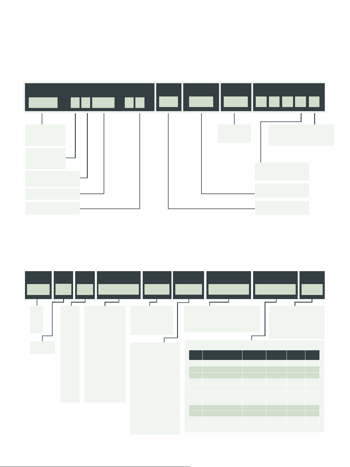
Drive part number key:
Identification Label
Derivative
Electrical Specification
Configuration
M753 - A 101 2 00022
Digitax HD range
M750 - EtherNet
M751 – Base
M753 – EtherCAT
Frame Size:
01 – frame 1
02 – frame 2
03 – frame 3
Voltage Rating:
2-200 V (200-240 ± 10%)
4-400 V (380-480 ± 10%)
Current Rating:
Nominal current rating x 10
Safety:
1 – Standard (2 x STO)
*For EtherNet and MCi versions, Option Modules are required separately. See page 29 for order codes.
Encoder
Interface
0
Documentation
1 00
Default
Region:
00 - 50 Hz
01 - 60 Hz
Optional Build
A 1B 1 0
Display option:
0 – KI-Compact Display not fitted
1 – KI-Compact Display fitted –
M750 and M753 only
Option module support:
AB10 – Not fitted
AB11 – Fitted – M751 only
Documentation:
1 – Multilingual
Encoder Interface:
0 – Standard
Unimotor HD ordering information
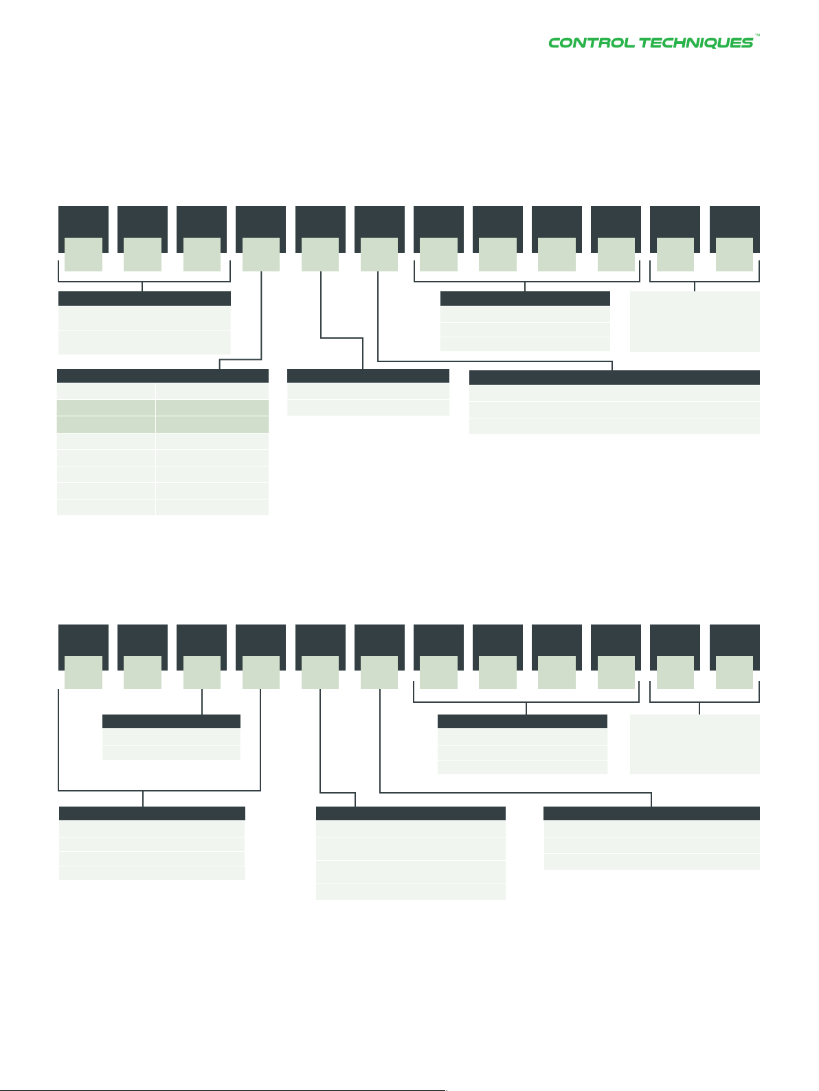
Motor part number key:
Frame
size
089
055
067
089
115
142
190
ED = 200V
UD = 400V
Motor
voltage
Stator
length*
Rated
speed
UD 0 B
055-
067
A
B
C
089
A
B
C
115
B
C
D
142
C
D
E
190
C
D
F
055 Frame
30 = 3000 rpm
60 = 6000 rpm
067 Frame
30 = 3000 rpm
60 = 6000 rpm
089 Frame
30 = 3000 rpm
40 = 4000 rpm
60 = 6000 rpm
115 Frame
20 = 2000 rpm
30 = 3000 rpm
142 Frame
10 = 1000 rpm
15 = 1500 rpm
20 = 2000 rpm
30 = 3000 rpm
190 Frame
10 = 1000 rpm
15 = 1500 rpm
20 = 2000 rpm
Brake Connection
0 = Not fitted
5 = Parking
Brake (fibre)
6 = Parking
Brake (resin)
x = Special
Size 1
B = Power and signal
90° rotatable
D= Single cable, power
& Signal combined,
90° rotatable
Size 1.5
J = Power and signal 90°
rotatable
E = Single cable, power
& signal combined,
90° rotatable
Single cable only must be
fitted with KTY thermistor
and is only available with
certain feedback options.
Please check before
ordering.
1
type*
Output shaft Feedback
device
A CA30
A = Key
B = Plain
E = Key with half
F = Key and half key supplied separately
Code Type Incremental
2
key fitted
055 and 067 frame sizes
resolution
AR Resolver 14 bit - ±600” no
EG Absolute (Multi turn) 19 bit 12 bit ±120” yes
FG Absolute (Single turn) 19 bit - ±120” yes
TL Absolute (Multi turn) 17 bit 12 bit ±120” no
UL Absolute (Single turn) 17 bit - ±120” no
089 to 190 frame sizes
AE Resolver 14 bit - ±720” no
EF Absolute (Multi turn) 19 bit 12 bit ±65” yes
FF Absolute (Single turn) 19 bit - ±65” yes
RA Absolute (Multi turn) 20 bit 12 bit ±52” no
SA Absolute (Single turn) 20 bit - ±52” no
A = Standard + PTC
C = Standard inertia +
2
E = Standard + PTC
Absolute
resolution
KTY84-130
Thermistor
Thermistor + Lifting
brackets (190 frame)
Accuracy Single
Inertia +
thermistor
type
AB
cable
*For stator length and connection type see pages 38 - 43
1
not available for 055 & 190 frames
2
n
ot available on 055 frame.
32
Additional feedback options available on request.
Page 2
Cables and connections
Power cable part number key:
FIELD NUMBER
1 32 4 5 76 8 9 1110 12
M BB A A OA O 2 S5 S
Cable & jacket type (field No 1,2 &3)
MBB = power braked
4 w + 2 w + screen, PUR jacket
MSB = power
4 w + screen, PUR jacket
Phase & conductor size (field No 4)
MSB = Un-braked MBB = Braked
2
A = 1 mm
B = 2.5 mm
C = 4 mm + 1 mm
D = 6 mm + 1 mm
E = 10 mm + 1 mm
F = 16 mm + 1 mm
G = 25 mm + 1 mm
*Length meter / cable requiring (cm) lengths will be rounded up to the next highest half meter; Eg. 2.1 will be changed to a 2.5 meter cable.
Maximum cable length refer to page 34
2
+ 0.5 mm
+ 0.5 mm
2
2
Drive end connection * (field No 5)
A = Ultrasonic welding
X = Cut end
Length meter * (field No 7, 8, 9 & 10)
0010 = 1 meter
0025 = 2.5 meter
0500 = 50 meters
Motor end connection (field No 6)
A = 6 way power size 1 from 1 to 4 mm
C = 6 way power size 1.5 from 6 to 16 mm
X = Cut end
Optional:
Progressive alphanumeric
code for custom special
requests (field No 11 & 12)
2
Signal cable part number key:
FIELD NUMBER
1 32 4 5 76 8 9 1110 12
S BI A B OA O 2 S5 S
Jacket type (field No 3)
A = PVC fixed installation
B = PUR dynamic installation
Cable & jacket type* (field No 1,2 & 4)
SI*A = CR, CA, EM, FM, EC, FC, EB, FB
SR*B = AR, AE
SS*C = TL, UL, RA, SA
SE*E = EF, FF, EG, FG, GB, HB, EN, FN
* Length meter/cable requiring (cm) lengths will be rounded up to the next highest half meter; Eg. 2.1 will be changed to a 2.5 meter cable.
Maximum cable length refer to page 34
Drive end connection (field No 5)
B = Flying leads
F = Low profile 90 deg 15 way connector
(inc. SC Endat)
T = Endat only low profile 90 Deg 15
way connector
X = Cut end
Length meter * (field No 7, 8, 9 & 10)
0010 = 1 meter
0025 = 2.5 meters
0500 = 50 meters
Motor end connection (field No 6)
A = Unimotor 17 way no speedtec connector
B = Unimotor 12 way no speedtec connector
X = Cut end
DRIVE SPECIALISTS SINCE 1973www.controltechniques.com32 33
Optional:
Progressive alphanumeric
code for custom special
requests (field No 11 & 12)
Page 3

SERVO DRIVE SERIES
Cables and connections
Hybrid cable part number key:
FIELD NUMBER
1 32 4 5 76 8 9 1110 12
H BY A A OA O 2 S5 S
Cable & jacket type (fi eld No 1,2 &3)
HYB = power standard
4 w + 2 brake + 6 signal +
screen, PUR desina orange.
Phase & conductor size (fi eld No 4)
A = 1.5 mm
B = 2.5 mm2 + 1 mm
C = 4 mm2 + 1 mm
2
+ 0.75 mm
2
2
2
Length meter * (fi eld No 7, 8, 9 & 10)
0010 = 1 meter
0025 = 2.5 meters
0500 = 50 meters
Drive end connection (fi eld No 5)
A = ULTRASONIC WELDING and 15 way High Density D Sub
for signal
D = Digitax HD Size 01, 02 & 03
E = Digitax HD Size 01 & 02 complete with EMC bracket and
terminal block fi tted
F = Digitax HD Size 03 complete with EMC bracket and terminal
block fi tted
X = Cut end
* Length meter / cable requiring (cm) lengths will be rounded up to the next highest
half meter; Eg. 2.1 will be changed to a 2.5 meter cable
Optional:
Progressive alphanumeric
code for custom special
requests (fi eld No 11 & 12)
Motor end connection (fi eld No 6)
A = Hybrid connector Size 1
B = Hybrid connector Size 1.5
X = Cut end
Maximum cable assembly length refer to table below
34
 Loading...