

Control Techniques SE11200025, SE11200075, SE2D200150, SE2D200220, SE11200037 User Manual
...Page 1
EF
User Guide
Commander SE
Sizes 1 to 4
Variable speed drive for 3 phase induction
motors from 0.25kW to 15kW
Part No. 0452-0033
Issue Number: 5
www.controltechniques.com
Page 2

WARNING
General Information
The manufacturer accepts noliability for any consequences resulting from
inappropriate, negligent or incorrect installation or adjustment of theoptional
operating parametersofthe equipment or from mismatchingthe variablespeed
drive (Drive)with the motor.
The contentsof thisUser Guideare believedto be correct at the t ime of printing.
In the interestsof a commitmentto a policy of continuousdevelopment and
improvement, the manufacturer reserves the right to change the specification of
the product or its performance, or the contents of the UserGuide, without notice.
All rightsreserved. No parts ofthis UserGuide maybe reproduced or transmitted
in any form or by any means, electrical or mechanical including photocopying,
recording or by an informationstorage or retrievalsystem, without permission in
writing from the publisher.
IMPORTANT
Drive software version
This product is supplied with the latest version of user-interface and machine
control software. Ifthis product isto beused in a new or existingsystem withother
Commander SE Drives, there may be some differences between their software
and the software in this product. These differences may causethis productto
function differently. Thismay also a pply to Drives returned from a Control
Techniques Service Centre.
If there is any doubt, contact a Control Techniques Drive Centre.
Copyright © August 2000 ControlTechniques Drives Limited
IssueCode: 5
Software: V01.08.00 onwards
Commander SE User Guide
Issue Number5
Page 3

Contents
1 Safety Information 3
1.1 Warnings, Cautions and notes 3
1.2 Electricalsafety - general warning 3
1.3 System design and safety of personnel 3
1.4 Environmentallimits 4
1.5 Compliance with regulations 4
1.6 Motor 4
1.7 Adjusting parameters 4
2 Options 5
3 Technical Data 6
3.1 Power dependant rating data 6
3.2 General data 13
3.3 RFI Filters 14
4 Installing the Drive 17
4.1 Safety information 17
4.2 Planning the installation 17
4.3 Mechanicalinstallation 18
4.4 Electrical installation 21
4.5 Electromagnetic compatibility (EMC) 24
5 Terminals 30
5.1 Power terminal connections 30
5.2 Control terminal connections 31
5.3 Serial communication connections 32
5.4 Control terminal specifications 32
6 Handling and Programming 35
6.1 Display and keypad 35
6.2 Display Messages 36
6.3 Selecting and changing parameters 36
6.4 Saving parameters 37
6.5 Security codes 37
6.6 Setting a security code 37
6.7 Unlockinga security code 38
6.8 Set security back to zero (0) - no security 38
6.9 Setting to default values 38
6.10 Level 1 and level 2 parameter descriptions 38
7 Getting Started - Bench Testing 53
7.1 Terminal control 53
7.2 Keypad control 55
Commander SE User Guide
Issue Number 5
Page 4

8 Diagnostics and Protective Features 57
8.1 Trip codes 57
8.2 Alarm warnings 58
8.3 HF-Hardware fault trip codes 59
9 Parameter List 60
10 Advanced Functions 61
10.1 Speed control 61
10.2 Ramps 61
10.3 Torque control 61
10.4 Stopping 61
10.5 Programmable I/O 61
10.6 Motorprotection 61
10.7 Monitoring 61
10.8 Auxiliary functions 61
10.9 Second motor selection 61
11 UL Listing Information 62
11.1 Common UL information 62
11.2 Power dependantUL information 62
Commander SE User Guide
Issue Number5
Page 5
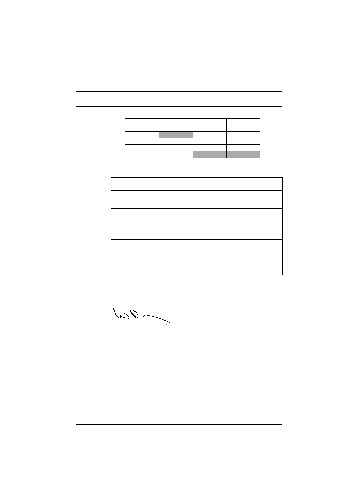
Declaration of Conformity
Control Techniques, The Gro, Newtown, Powys, UK. SY16 3BE
SE11200025 SE11200037 SE11200055 SE11200075
SE2D200075 SE2D200110 SE2D200150 SE2D200220
SE23200400
SE23400150 SE23400220 SE23400300 SE23400400
SE33200550 SE33400550 SE33200750 SE33400750
SE43401100 SE43401500
The AC variable speed drive products listed above, have been designed and
manufactured in accordancewith the following European harmonised,national
and international standards:
EN60249 Base materials for printed circuits
IEC326-1 Printed boards: generalinformation forthe specification writer
IEC326-5
IEC326-6 Printed boards: specification for multilayerprinted boards
IEC664-1
EN60529 Degrees of protection provided by enclosures(IP code)
UL94 Flammability rating of plasticmaterials
UL508C Standard for power conversion equipment
*EN50081-1
EN50081-2 Generic emission standard forthe industrial envi ronment
EN50082-2 Generic immunity standardfor the industrial envir onment
EN61800-3
*Applies to Size 1 units only.
Printed boards: specification for single- anddouble-sided printed boards
with plated-throughholes
Insulation co-ordinationfor equipment within low-voltage systems:
principles, requirements and tests
Generic emission standardfor the residential, commercialand light
industrial environment
Adjustable speed electricalpower drive sy stems - Part 3: EMC produc t
standard including specific test methods
These products comply with the Low Voltage Directive 73/23/EEC, the
Electromagnetic Compatibility(EMC) Directive 89/336/EEC and the CE Marking
Directive 93/68/EEC.
These electronic Drive products are intended to be used with appropriate
motors, controllers, electrical protection components and other equipment
to formcompleteend productsor systems. Compliance with safetyand EMC
regulations depends upon installing and configuring Drives correctly,
includingusing thespecified input filters. TheDrives must beinstalled only
by professional assemblers who are familiar with requirements for safety
and EMC. Theassembler is responsible forensuringthat theend product or
system complies with all the relevant laws in the country where it is to be
used.Refer to this User Guide. A Commander SE EMC Data Sheet is also
available giving detailed EMC information.
SE23400075 SE23400110
W. Drury
Executive VP Technology
Date: 8th March 2000
Commander SE User Guide
Issue Number 5 1
Page 6

Addendum: Spinning motor software
TwoissueshavebeenfoundduringlaboratorytestingofCommanderSErelating
to the use of spinning motor software,parameter33 (parameter 6.09 in
advancedparameters).
The firstissue appears both in open loop vectorcontrol (as default)and fixed
boost mode. A conditionoccurs whenthe Drive's software releases the motor
from spinningmotor control back to normal control. This issue is more
pronounced on Commander SE sizes 3 and 4 but is present to a lesser extent
on CommanderSEsizes 1 and 2. Itis notbelievedthatthisissuewillcause any
field problems.
The secondissue relates to the operation of the spinningmotor software while
infixedboostmode,parameter5.14 setto mode2. (Note that Fixed boostmode
can only be selected from the advanced parameters throughserial
communications). The problem occurs if the motorto be 'caught' is rotating in
the reversedirection. While attempting to 'catch' the motor, theDrive will tripon
OI.AC. If the motor to be 'caught' is rotating in the forward direction or at
standstill, thisproblem will not occur. Also, if the Drive is set up in open loop
vectormode (as default) this problem will not occur.
Commander SE User Guide
2 IssueNumber5
Page 7

1 Safety Information
1.1 Warnings, Cautions and notes
A Warning contains information which is essential for avoiding a safety hazard.
WARNING
A
Caution contains information which isnecessary for avoiding a risk of damage to
CAUTION
NOTE
1.2 Electrical safety - general warning
1.3 System design and safety of personnel
the product or other equipment.
Note contains information which helps to ensure correct operation of the product.
A
The voltages used in the Drive can cause severe electricalshock and/orburns, and
couldbe lethal. Extreme care is necessaryat alltimes when workingwithor adjacent
to the Drive.
Specific warnings are given at the relevant places in this User Guide.
The Driveis intendedas a componentfor professional incorporation into complete
equipmentor a system. Ifinstalledincorrectly,theDrivemaypresentasafetyhazard.
The Drive uses high voltage and currents, carries a high level of stored electrical
energy,and is used to control equipment which can cause injury.
Close attention is required to the electrical installation andthe system designto avoid
hazards,either in normal operationor in the eventof equipment malfunction. System
design,installation,commissioningandmaintenancemustbecarriedoutbypersonnel
who have the necessary training and experience. They must read this safety
information and this User Guide carefully.
The STOP function of the Drive does notremove dangerous voltages from the output
of the Drive or from any external option unit.
Carefulconsiderationmust be givento the functionsof t he Drive which might resultin
a hazard, either throughtheir intendedfunctions or throughincorrect operationdue to
afault.
In any application where a malfunction of the Drive could lead to damage, loss or
injury,a risk analysismust be carried out, and where necessary,further measures
takentoreducetherisk.
The STOPand STARTcontrols or electrical inputs of the Drivemust notbe relied
upon to ensure safety of personnel. If a safety hazard could exist from
unexpected startingof t he Drive, an interlock that electricallyisolatesthe Drive
from the AC supply must be installed to prevent the motor being inadvertently
started.
To ensuremechanical safety, additionalsafety devices suchas electro-mechanical
interlocks and overspeed protection devices may be required. TheDrive must not be
used in a safety critical applicationwithout additional high integrity protection against
hazards arising from a malfunction.
Undercertain conditions, the Drivecan suddenlydiscontinue control of the motor.If
the load on the motor couldcausethe motor speed to be increased(e.g.in hoistsand
Commander SE User Guide
Issue Number 5 3
Page 8

cranes),a separatemethod of brakingand stopping must be used(e.g. a mechanical
brake).
1.4 Environmental limits
Instructions in thisUser Guideregarding transport, storage, installation and use of the
Drivemustbecompliedwith,includingthespecifiedenvironmentallimits. Drivesmust
not be subjected to excessive physical f orce.
1.5 Compliance with regulations
The installeris responsible for complyingwith all relevantregulations, such as national
wiring regulations, accident preventionregulationsand electromagnetic compatibility
(EMC) regulations. Particular attention must be given to the cross-sectional areas of
conductors, the selectionof fuses or other protection, and protectiveearth (ground)
connections.
This UserGuide contains instruction for achieving compliance with specificEMC
standards.
Within the European Union, all machinery in which this product is used must comply
with the following directives:
• 97/37/EC: Safety of machinery.
• 89/336/EEC: Electromagnetic Compatibility.
1.6 Motor
Ensure the motorisinstalled in accordance withthe manufacturer’srecommendations.
Ensure the motor shaft is not exposed.
Standard squirrel cage induction motors are designedforsingle speed operation. Ifit
is intended to use the capabilityof the Drive to run a motor at speedsabove its
designed maximum,it is strongly recommended that the manufacturer is consulted
first.
Low speeds may causethe motor to overheatbecausethe cooling fan becomes less
effective. The motor should be fitted with a protection thermistor. If necessary, an
electric forced vent fan should be used.
1.7 Adjusting parameters
Some parameters havea profoundeffect on the operation ofthe Drive. Theymust not
be altered without careful consideration of the impact on the controlled system.
Measures must be taken to prevent unwanted changes due to error or tampering.
Commander SE User Guide
4 IssueNumber5
Page 9

2 Options
The following options are available for Commander SE;
• Quickey for rapid parameter transfer (SE55)
• Standard andlow earth leakage footprint / sidemountingRFI filters and low cost
panel mountingRFI filters
• Universal Keypad, IP65, hand held or door mounting plain text, LCD display
•SESoftWindows
• +10V to -10V analog input card for bi-directional input reference (SE51)
• Cablescreeningbracket and screeningclamps to providea convenientway of
connecting supply, motor and control cable screensto ground (SE11, 12, 13 &
14)
• EMC Data Sheets
• Through hole mounting plate drawings to allowheatsink to be put outside main
cubicle
• EIA232 to EIA485 (2 wire) converter for connecting between the Drive and PC
when using SE Soft(SE71 Communications lead)
• Fieldbus Communications:
• Commander S E Advanced User Guide: (See Chapter 10 of this User Guide for a
list of advanced functions).
• AC inputline reactors
• Braking resistors and mounting plate
For further details on the above options and availability, contact your local Control
Techniques DriveCentre or Distributor.
™ based set-upsoftwarefor advancedprogramming
Profibus DP (SE73)
Device Net (SE77)
CAN Open (SE77)
Interbus (SE74)
CT Net (SE75)
Commander SE User Guide
Issue Number 5 5
Page 10
3TechnicalData
3.1 Power dependant rating data
Model code explanation
SE1 -framesize1,SE2 -framesize2,SE3 - frame size 3,
SE4 -framesize4.
1 - single phase,D - Dual rating (single and three phase), 3 - three phase
2-230VAC nominalinput voltage, 4 - 400VAC nominal input voltage
00 - for expansionof Drive powerrange
025 to 1500 -0.25kWto15kWoutputpower
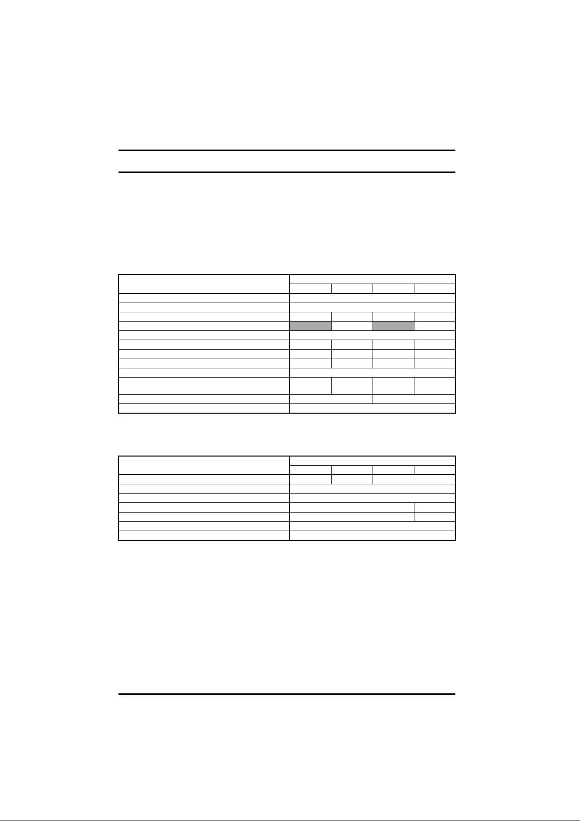
Table 3.1 CommanderSE Size 1
MODEL SE11200...
AC supply voltage andfrequency Single phase 200 - 240V +/- 10% 48 - 62Hz
Input displacement factor (cosφ)>0.97
Nominal motor power - kW 0.25 0.37 0.55 0.75
Nominal motor power - HP
Output voltage and frequency 3 phase, 0 to input voltage,0 to 1000Hz
100% RMS output current - A 1.5 2.3 3.1 4.3
150% overload current for 60 secs- A 2.3 3.5 4.7 6.5
Typical full loadinput current - A* 5.6 6.5 8.8 11.4
Typical inrush current - A** (duration <10ms) 100
Drive power losses at 230VAC at 6kHz switching
frequency - W 18 24 37 56
Weight - kg/lb 1.1/2.4 1.25/2.75
Cooling fan fitted No
* See section 3.1.1.
** For an explanation of inrush current, see section 3.1.2.
Table 3.2 Recommended supply f uses and cables
MODEL SE11200...
Recommended input supply fuse - A 6 10 16
Control cable mm² ≥ 0.5
Recommended input cable mm² 1.0 1.5
Recommendedmotor cable mm² 1.0
AWG 20
AWG 16 14
AWG 16
025 037 055 075
0.50 1.0
025 037 055 075
Commander SE User Guide
6 IssueNumber5
Page 11
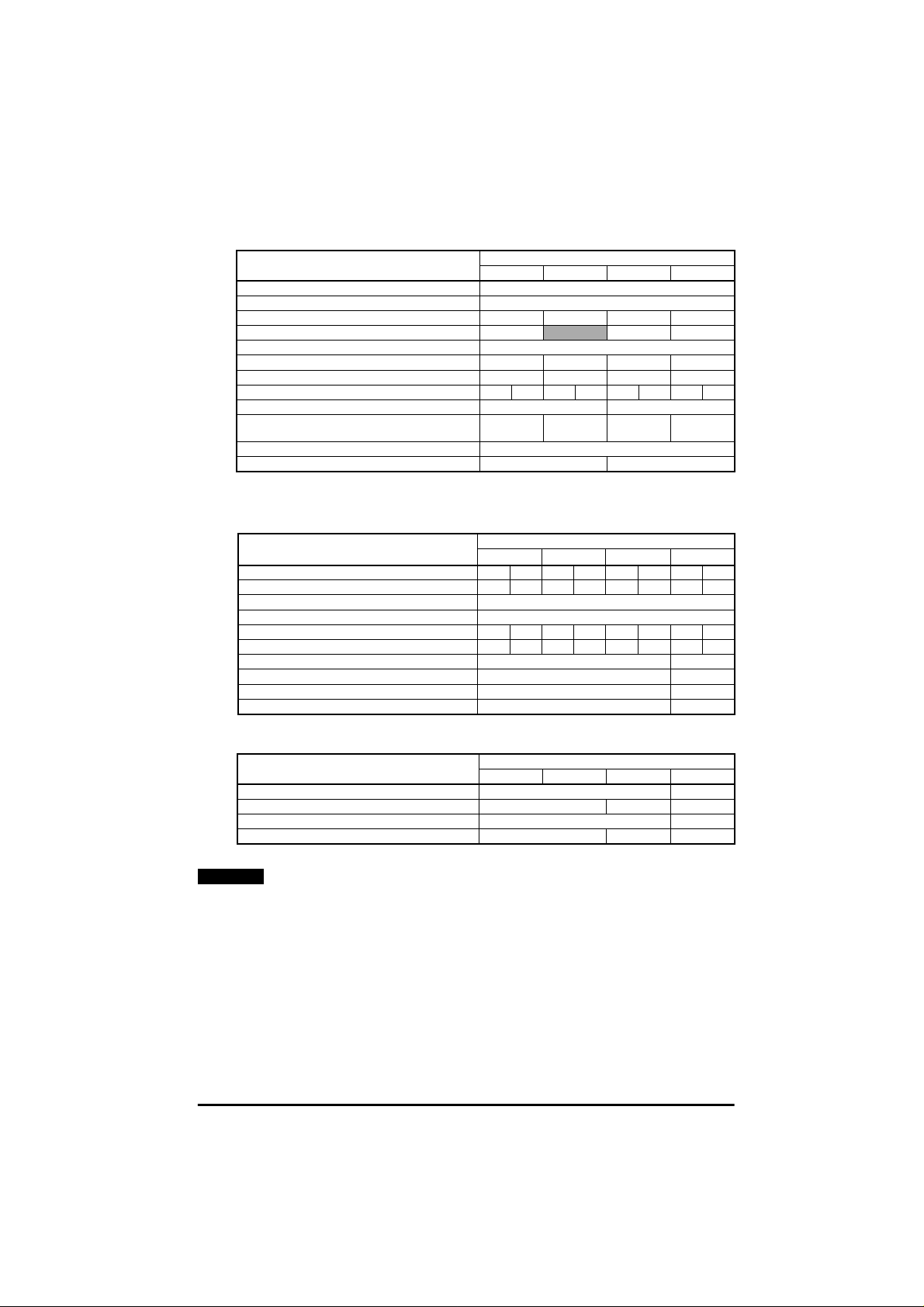
Table 3.3 Commander SE Size 2, 200V dual rated units
MODEL SE2D200...
AC supply voltage andfrequency Single or 3 phase 200 to 240V +/- 10%, 48to 62Hz
Input displacement factor (cosφ)>0.97
Nominal motor power - kW 0.75 1.1 1.5 2.2
Nominal motor power - HP 1.0
Output voltage and frequency 3 phase, 0 to input voltage, 0 to 1000Hz
100% RMS output current - A 4.3 5.8 7.5 10.0
150% overload current for 60 secs- A 6.5 8.7 11.3 15.9
Typical full loadinput current - A* 1ph/3ph 11.0 5.5 15.1 7.9 19.3 9.6 26.2 13.1
Typical inrush current - A**(duration <10ms) 55 35
Drive power losses at 230VAC at 6kHz switching
frequency - W 54 69 88 125
Weight - kg/lb 2.75 / 6
Cooling fan fitted No Yes
075 110 150 220
2.0 3.0
* See section 3.1.1.
** For an explanationof inrush current, see section 3 .1.2.
Table 3.4 Recommended supply fuses and cables
MODEL SE2D200...
Recommended input supply fuse - A 16 10 20 16 25 16 32 20
Control cable mm² ≥ 0.5
AWG 20
Recommended input cable mm² 1.5 1.0 2.5 1.5 2.5 1.5 4.0 2.5
AWG1416121412141012
Recommended motor cable mm² 1.0 1.5
AWG 16 14
Recommended brakingresistor cable mm² 1.0 1.5
AWG 16 14
075
1ph3ph1ph3ph1ph3ph1ph3ph
110 150 220
Table 3.5 Braking resistors
MODEL SE2D200...
Minimum braking resistor value - Ω 50 40
Recommended brakingresistor value - Ω 100 75 50
Maximum braking current- A 9 11
Resistor peak power rating - kW 1.8 2.4 3.5
NOTE
Before fitting a braking resistor please read the information on Braking, and
075 110 150 220
the Warnings on High Temperatures and Overload Protectionat the end of
this section.
Commander SE User Guide
Issue Number 5 7
Page 12
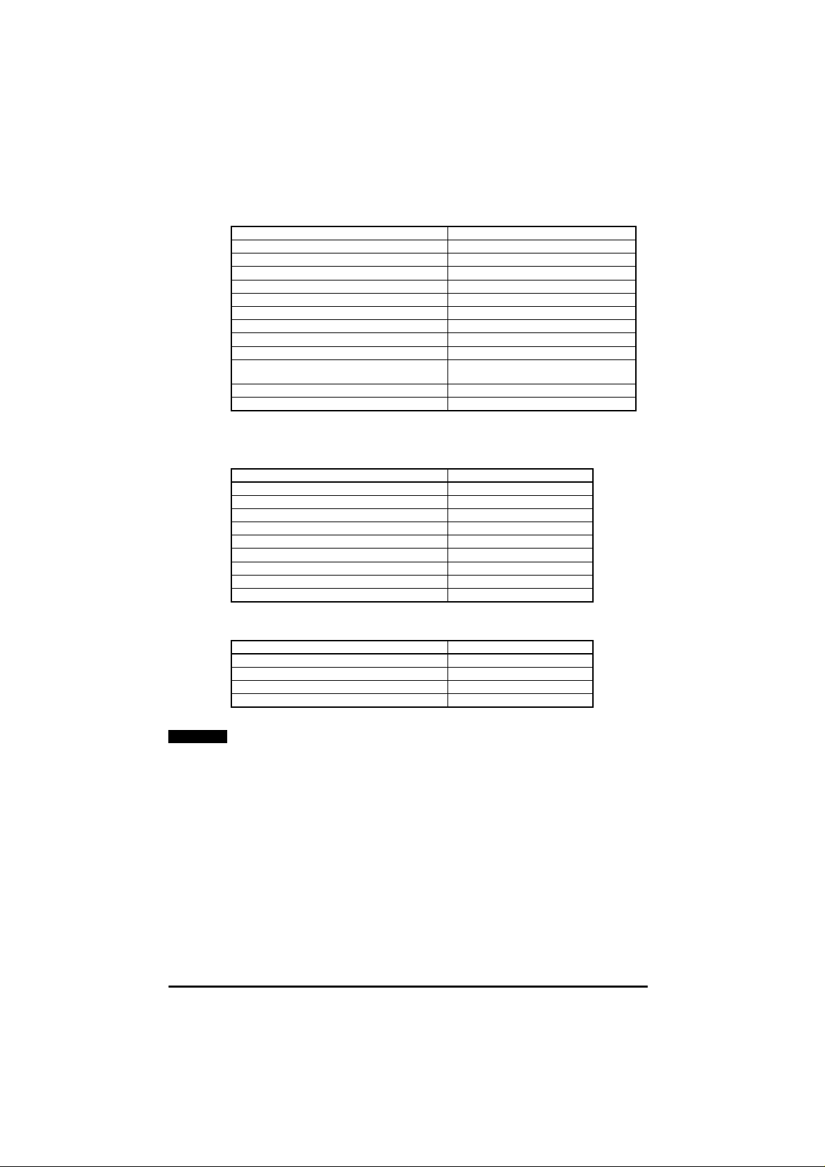
Table 3.6 CommanderSE Size 2, 200V Three phase units
AC supply voltage andfrequency 3 phase 200 to 240V +/- 10%,48 to 62Hz
Input displacement factor (c osφ) >0.97
Nominal motor power - kW 4
Nominal motor power - HP 5
Output voltage and frequency 3 phase,0 to input voltage, 0 to 1000Hz
100% RMS output current - A 17.0
150% overload current for 60 secs- A 25.5
Typical ful lload input current- A* 21
Typical inrush current - A** (duration <10ms) 35
Drive power losses at 230VAC at 6kHz switching
frequency - W 174
Weight - kg/lb 2.75 / 6
Cooling fan fitted Yes
MODEL SE23200400
* See section 3.1.1.
** For an explanation of inrush current, see section 3.1.2.
Table 3.7 Recommended supply f uses and cables
Recommended input supply fuse - A 32
Control cable mm² ≥ 0.5
Recommended input cable mm² 4.0
Recommended motor cable mm² 2.5
Recommended braking resistor cable mm² 2.5
MODEL SE23200400
AWG 20
AWG 10
AWG 12
AWG 12
Table 3.8 Braking resistors
MODEL SE23200400
NOTE
Minimum braking resistor value - Ω 30
Recommended brakingresistor value - Ω 30
Maximum braking current- A 14
Resistor peak power rating - kW 5.9
Before fittinga braking resistor please read the information on Braking, and
the Warnings on HighTemperaturesand Overload Protection at the end of
this section.
Commander SE User Guide
8 IssueNumber5
Page 13
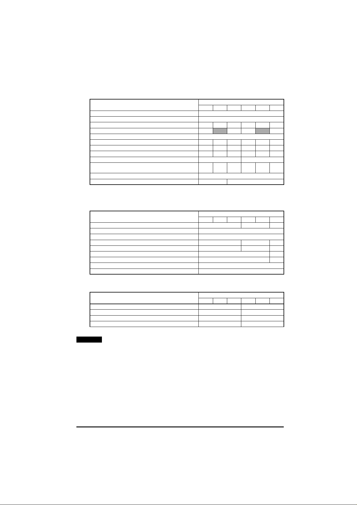
Table 3.9 Commander SE Size 2, 400V Three phase units
MODEL SE23400...
AC supply voltage andfrequency 3 phase 380 to 480V +/- 10%, 48 to 62Hz
Input displacement fac tor(cos φ)>0.97
Nominal motor power - kW 0.75 1.1 1.5 2.2 3.0 4.0
Nominal motor power - HP 1.0
Output voltage and frequency 3phase, 0 to input voltage, 0 to 1000Hz
100% RMS output current - A 2.1 3.0 4.2 5.8 7.6 9.5
150% overload current for 60 secs - A 3.2 4.5 6.3 8.7 11.4 14.3
Typical full loadinput current - A*400V, 50Hz/480V, 60Hz 3.6 4.8 6.4 9.3 11 14
Typical inrush current - A** (duration <10ms) 90 60
Drive power losses at 480VAC at 6kHz switching
frequency - W 43 57 77 97 122 158
Weight - kg/lb 2.75 / 6
Cooling fan fitted No Yes
075 110 150 220 300 400
2.0 3.0 5.0
* See section 3.1.1.
** For an explanationof inrush current, see section 3 .1.2.
Table 3.10 Recommended fuses and cables
MODEL SE23400...
Recommended inputsupply fuse - A 10 16 20
Control cable mm² ≥ 0.5
AWG 20
Recommended inputcable mm² 1.0 1.5 2.5
AWG 16 14 12
Recommended motor cable mm² 1.0 1.5
AWG 16 14
Recommended brak ingresistor cable mm² 1.5
AWG 14
075 110 150 220 300 400
Table 3.11 Braking Resistors
MODEL SE23400...
Minimum braking res istor value - Ω 100 75
Recommended brak ingresistor value - Ω 200 100
Maximum braking current - A 10 12.5
Resistor peak power rating - kW 3.4 6.9
NOTE
Before fitting a braking resistor please read the information on Braking, and
075 110 150 220 300 400
the Warnings on High Temperatures and Overload Protectionat the end of
this section.
Commander SE User Guide
Issue Number 5 9
Page 14
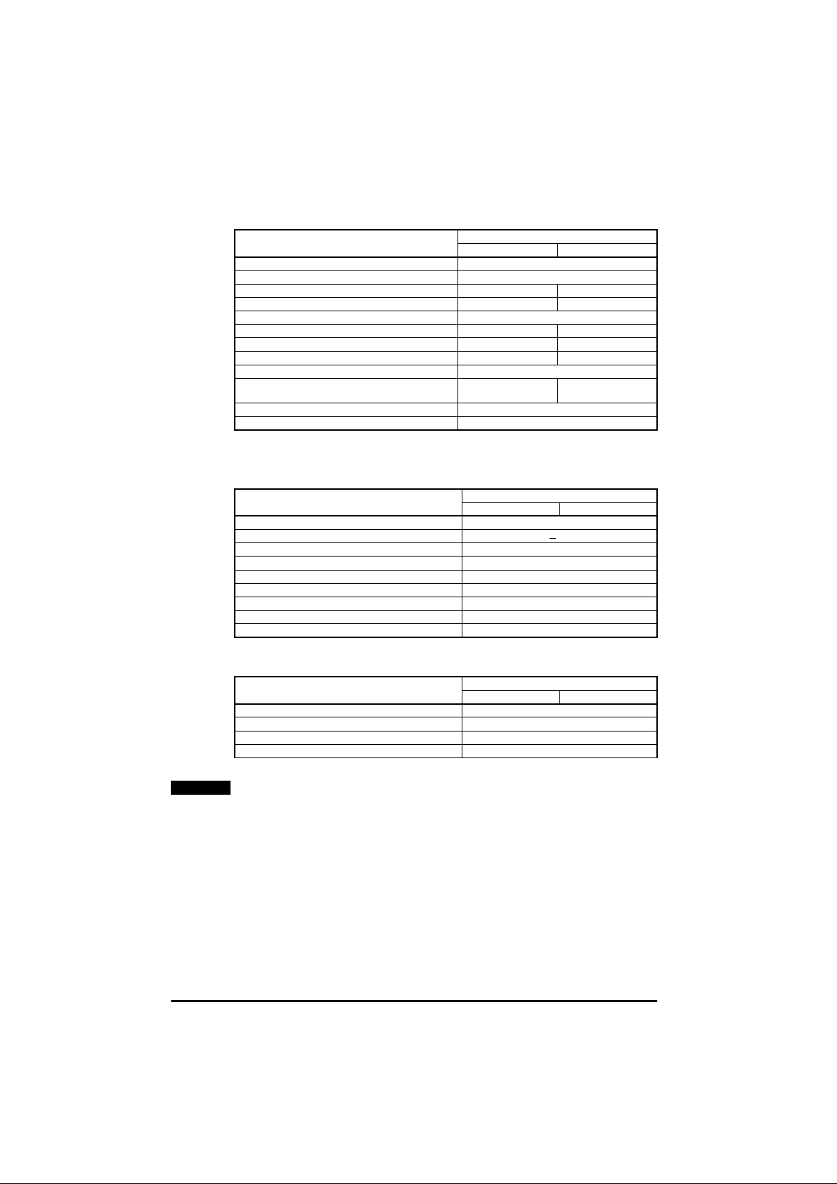
Table 3.12 CommanderSE Size 3, 200V units
MODEL SE33200...
AC supply voltage andfrequency 3 phase 200 to 240V +/-10%,48 to 62Hz
Input displacement factor (c osφ) >0.97
Nominal motor power - kW 5.5 7.5
Nominal motor power - HP 7.5 10.0
Output voltage and frequency 3 phase, 0 to input voltage, 0 to 1000Hz
100% RMS output current - A 25.0 28.5
150% overload current for 60 secs- A 37.5 42.8
Typical full loadinput current - A* 22.8 24.6
Typical inrush current - A** (duration <10ms) 44
Drive power losses at 230VAC at 6kHz switching
frequency - W
Weight - kg/lb 6 / 13.2
Cooling fan fitted Yes
550 750
230 305
* See section 3.1.1.
** For an explanation of inrush current, see section 3.1.2.
Table 3.13 Recommended fuses and cables
MODEL SE33200...
Recommended input supply fuse - A 30
Control cablemm² >
AWG 20
Recommended input cablemm² 4.0
AWG 10
Recommendedmotor cablemm² 4.0
AWG 10
Recommended brakingresistor cablemm² 4.0
AWG 10
550 750
0.5
Table 3.14 Braking Resistors
NOTE
MODEL SE33200...
Minimum braking resistor value - Ω 11.0
Recommended brakingresistor value - Ω 15.0
Maximum braking current - A 28.0
Resistor peak power rating - kW 11.8
Before fittinga braking resistor please read the information on Braking, and
550 750
the Warnings on HighTemperaturesand Overload Protection at the end of
this section.
Commander SE User Guide
10 Issue Number5
Page 15
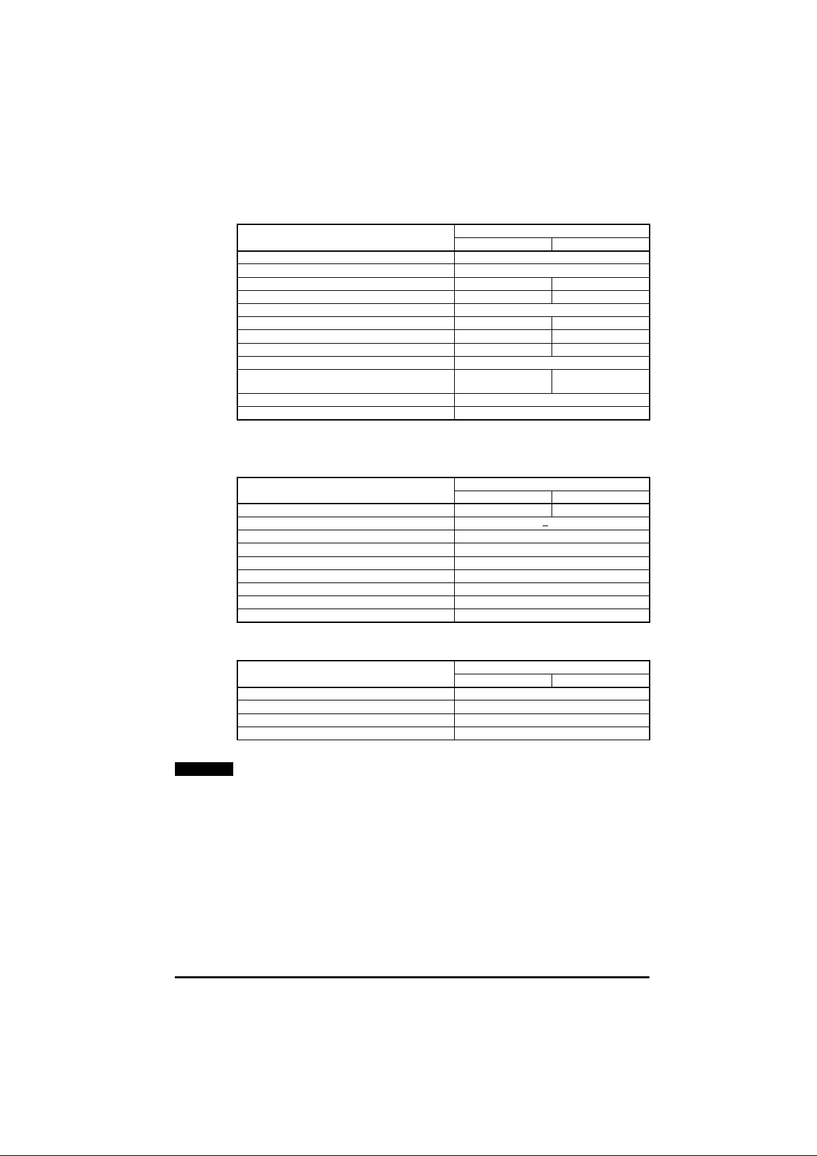
Table 3.15 Commander SE Size 3,400V units
MODEL SE33400...
AC supply voltage and frequency 3 phase 380 to 480V +/-10%, 48 to 62Hz
Input displacementfactor (cos φ)>0.97
Nominal motor power - kW 5.5 7.5
Nominal motor power - HP 7 .5 10.0
Output voltage and frequency 3 phase, 0 to input voltage, 0 to 1000Hz
100% RMS output current - A 13.0 16.5
150% overload current for 60 secs - A 19.5 24.8
Typical fullload input current - A* 13.0 15.4
Typical inrush current - A**(duration <10ms) 80
Drive power losses at480VAC at 6kHz switching
frequency - W
Weight - kg/lb 6 / 13.2
Cooling fan fitted Yes
550 750
190 270
* See section 3.1.1.
** For an explanationof inrush current, see section 3 .1.2.
Table 3.16 Recommended fuses and cables
MODEL SE33400...
Recommended inputsupply fuse - A 16 20
Control cable mm² >
AWG 20
Recommended inputcable mm² 2.5
AWG 12
Recommended motor cable mm² 2.5
AWG 12
Recommended braking resistor cable mm² 2.5
AWG 12
550 750
0.5
Table 3.17 Braking Resistors
NOTE
MODEL SE33400...
Minimum braking resistor value - Ω 33.0
Recommended braking resistor value - Ω 50
Maximum braking current - A 16.6
Resistor peak power rating - kW 13.8
Before fitting a braking resistor please read the information on Braking, and
550 750
the Warnings on High Temperatures and Overload Protectionat the end of
this section.
Commander SE User Guide
Issue Number 5 11
Page 16

Table 3.18 CommanderSE Size 4, 400V units
MODEL SE4340...
AC supply voltage andfrequency 3 phase 380 to 480V +/-10%,48 to 62Hz
Input displacement factor (c osφ) >0.97
Nominal motor power - kW 11 15
Nominal motor power - HP 15 20
Output voltage and frequency 3 phase, 0 to input voltage, 0 to 1000Hz
100% RMS output current - A 24.5 30.5
150% overload current for 60 secs- A 36.75 45.75
Typical full loadinput current - A* 23 27.4
Typical inrush current - A** (duration <10ms) 40
Drive power losses at 480VAC at 6kHz switching
frequency - W
Weight - kg/lb 11 / 24.2
Cooling fan fitted Yes
1100 1500
400 495
* See section 3.1.1.
** For an explanation of inrush current, see section 3.1.2.
Table 3.19 Recommended fuses and cables
MODEL SE4340...
Recommended input supply fuse - A 32 40
Control cable mm² >
AWG 20
Recommended input cable mm² 4.0
AWG 10
Recommended motor cable mm² 4.0 6.0
AWG 10 8
Recommended brakingresistor cable mm² 6.0
AWG 8
1100 1500
0.5
Table 3.20 Braking Resistors
NOTE
MODEL SE4340...
Minimum braking resistor value - Ω 27
Recommended brakingresistor value - Ω 40 30
Maximum braking current- A 30
Resistor peak power rating - kW 25.5
Before fittinga braking resistor please read the information on Braking, and
1100 1500
the Warnings on HighTemperaturesand Overload Protection at the end of
this section.
Commander SE User Guide
12 Issue Number5
Page 17
Braking Resistors - High Temperatures
Braking resistors can reach high temperatures. Locatebraking resistors so
WARNING
that damage cannot result. Use cable having insulation capable of
withstanding high temperatures.
Braking Resistors - Overload Protection
It is essential that an overload protection device is incorporated in the
WARNING
braking resistor circuit. This is described in section 5.1.1 Thermal
Protection Circuit for an Optional Braking Resistor.
3.1.1 * Input current
The input current values given could be exceeded where the supply fault current is
greater than 5kA or the phase voltages are not balanced. In thesecases, input line
reactors are recommended. See section 4.4.3.
3.1.2 **Temperature effects on inrush currents
Due to the design of the inrushcircuit,the inrushcurrentwill be loweron thefirst power
upof the Drive aftera periodofnon-useandwhentheDriveiscold.Theinrushcurrent
will increase when the time between power ups is short and the internal ambient
temperature within the Drive is high.
3.2 General data
IP Rating.
WARNING
Size1:
IP20
The IngressProtectionrating is applicableto theDrive
when the suppliedrubber grommetsare fitted into the
glandplate.
Sizes 2, 3 & 4:
IP20
The IngressProtectionrating is applicableto theDrive
when the suppliedrubber grommetsare fitted into the
glandplateandtheDriveismountedonasolidflat
surface.
If the Drive is not mounted in this way, hazardouslive parts will be exposed
and the IP Rating of the Drive willbe invalid.
Input phase
imbalance:
Phase imbalance not to exceed 2% negative phase
sequence
Ambient temperature: -10°Cto+40°C(14°Fto104°F) at 6kHz switching
frequency
-10°Cto+50°C(14°Fto122°F) at 3kHz switching
frequency with derating. SeeCommanderSE
Advanced User Guide for DeratingCurves.
Storage temperature: -40°Cto+60°C (-40°Fto140°F) for 12 months
maximum.
Altitude: Reduce the normal full-load currentby 1% for every
100m (325ft) above 1000m (3250ft)to a maximum of
4000m(13000ft).
Commander SE User Guide
Issue Number 5 13
Page 18

Humidity: Maximum relative humidity 95% (non-condensing)
Materials: Flammability rating of main enclosure:UL94-5VA
Grommets: UL94-V1
Vibration (random):
Vibration (sinusoidal)
Bump: Packaged - tested to 40g, 6ms, 100 times/directionfor
Frequency accuracy: 0.01%
Resolution: 0.1Hz
Output frequency
range:
Starts per hour: By using the electronic control terminals: Unlimited
Power up delay: 1 second maximum (Allow at least 1 second before
Serial
Communications:
Switching
Frequencies:
EMC: EN50082-2and EN61800-3 for immunity
Unpackaged - tested to 0.01g²/Hz (equivalentto 1.2g
rms)from5to150Hzfor1hourineachof3axesin
accordance with IEC68-2-34and IEC68-2-36.
Unpackaged - tested from2-9Hz, 3.5mmdisplacement;
9-200Hz10m/s
acceleration. Duration- 15 minutes in each of 3 axes.
Sweep rate 1 octave/minute.
Test in accordancewith IEC68-2-6.
all 6 directions as in IEC68-2-29
Unpackaged - tested to 25g, 6ms, 100 times/direction
for all 6 directions in accordancewith IEC68-2-29
0to1000Hz
By switching of the supply: 20 starts perhour maximum
(3 minute intervals between starts)
monitoring the state of the status relay contacts,
communicating with the Drivevia serial
communicationsetc.)
ANSI 2-wire EIA485 protocol via RJ45 connector
3, 6, and 12 kHzare available with Intelligent Thermal
Management software automaticallychangingthe
switching frequencies depending on load conditions,
heatsink temperature and output frequency, to prevent
heatsink overtemperature trips.
EN61800-3 second environment, withoutRFI filter
EN50081-1*, EN50081-2 and EN61800-3 first
environment,with optionalRFI filter.See sections3.3
and 4.5.
* Size 1 units only.
2
acceleration; 200-500Hz, 15m/s
2
3.3 R FI Filters
RFI f ilters are availableas optionalextra partswhere required.
NOTE
For compliance with EN61800-3 in the second environment, no filter is
required.
Commander SE User Guide
14 Issue Number5
Page 19
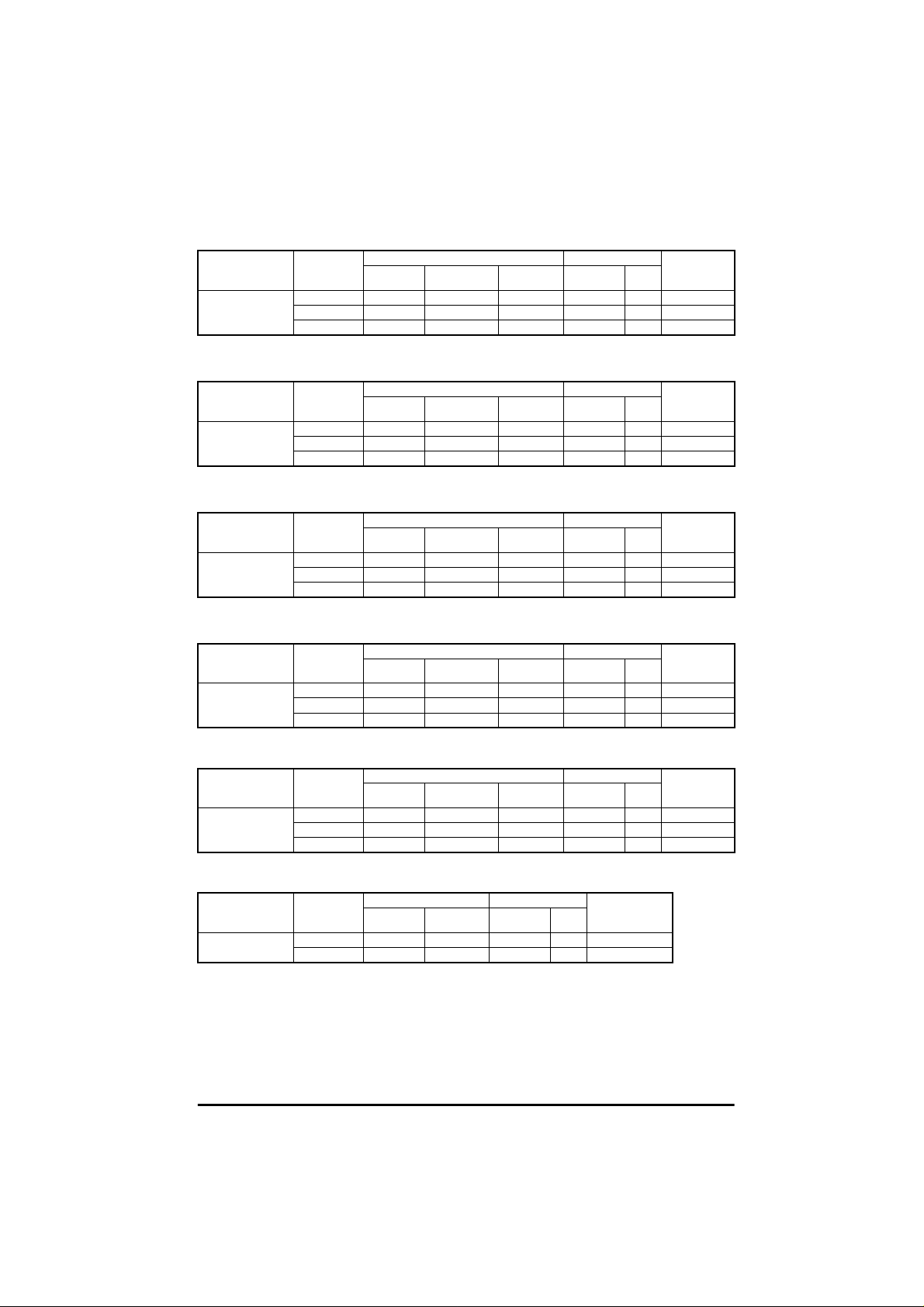
Table 3.21 Commander SE Size 1
Used with Filter Part
SE11200025 to
SE11200075
No
4200-6101 Y Y 20
4200-6102 Y Y Y 75
4200-6103 Y Y Y 15
Table 3.22 Commander SE Size 2 - 200V, 26A, 1 phase
Used with Filter Part
SE2D200075 to
SE2D200220
No
4200-6201 Y Y Y 100
4200-6204 Y Y 50
4200-6205 Y Y Y 15
Table 3.23 Commander SE Size 2 - 200 / 400V, 16A, 3 phase
Used with Filter Part
SE2D200075 to
SE2D200220
No
4200-6202 Y Y Y 100
4200-6304 Y Y 15
4200-6207 Y Y Y 45
Table 3.24 Commander SE Size 2 - 200 / 400V, 16A, 3 phase
Used with Filter Part
SE23400075 to
SE23400400
No
4200-6202 Y Y Y 100
4200-6304 Y Y 15
4200-6207 Y Y Y 20
Standard Low leakage Low cost Footprint Side
Filter Type Mounting Max motor
Filter Type Mounting Max motor
Standard Low leakage Low cost Footprint Side
Filter Type Mounting Max motor
Standard Low leakage Low cost Footprint Side
Filter Type Mounting Max motor
Standard Low leakage Low cost Footprint Side
cable length
(m)
cable length
(m)
cable length
(m)
cable length
(m)
Table 3.25 Commander SE Size 2 - 200V, 26A, 3 phase
Used with Filter Part
SE23200400 4200- 6203 Y Y Y 100
No
4200-6303 Y Y 15
4200-6209 Y Y Y 45
Standard Low leakage Low cost Footprint Side
Filter Type Mounting Max motor
cable length
(m)
Table 3.26 Commander SE Size 3 - 200V, 30A
Used with Filter Part
SE33200550 to
SE33200750
No
4200-6302 Y Y Y 100
4200-6303 Y Y 15
Filter Type Mounting Max motor
Standard Low cost Footprint Side
cable length
(m)
Commander SE User Guide
Issue Number 5 15
Page 20
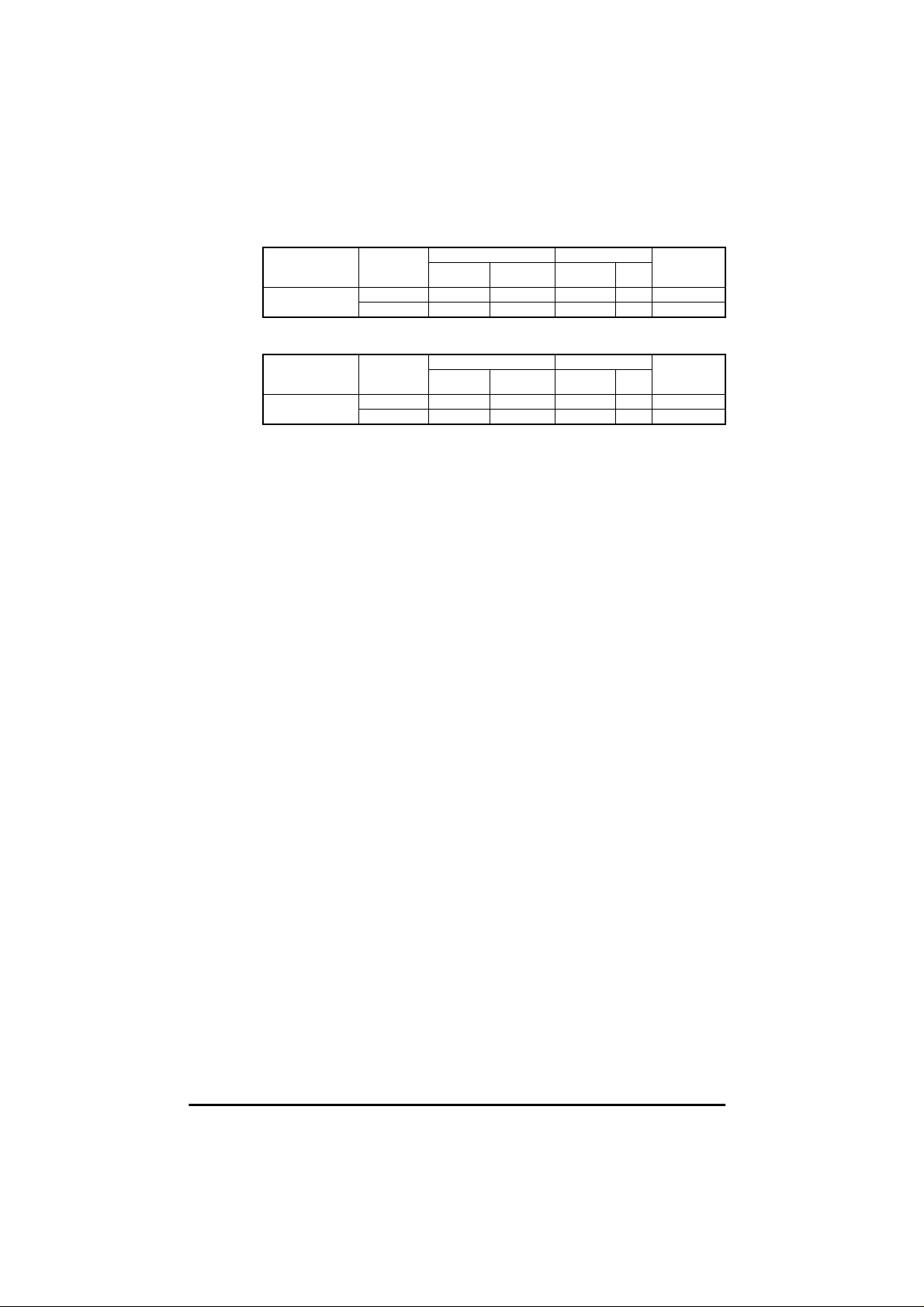
Table 3.27 CommanderSE Size 3 - 400V, 18A
Used with Filter Part
SE33400550 to
SE33400750
No
4200-6301 Y Y Y 100
4200-6304 Y Y 15
Filter Type Mounting Max motor
Standard Low cost Footprint Side
cable length
(m)
Table 3.28 CommanderSE Size 4
Used with Filter Part
SE43401100 to
SE43401500
No
4200-6401 Y Y Y 100
4200-6402 Y Y 15
Filter Type Mounting Max motor
Standard Low cost Footprint Side
cable length
(m)
For complete EMC information, refer to Section 4.5 Electromagnetic compatibility
(EMC).
Commander SE User Guide
16 Issue Number5
Page 21
4 Installing the Drive
4.1 Safety information
Follow the instructions
The mechanical and electrical installation instructions must be adhered to.
WARNING
WARNING
4.2 Planning the installation
Any questions or doubt should be referred to thesupplierof the equipment.
It is the responsibility of the owner or user to ensure that the installation of
the Drive and any external option unit, and the way in which they are
operated and maintained, comply with the requirements of the Health and
Safety at Work Act in the United Kingdom or applicable legislation and
regulations and codes of practice in the country in which the equipment is
used.
Competence of the installer
The Drive must be installed by professional assemblers who are familiar
with the requirements for safetyand EMC. The assembler is responsible for
ensuring that the end product or system complies with all the relevant laws
inthecountrywhereitistobeused.
The following considerations must bemade when planning the installation:
Access
Access must be restricted to authorised personnel only. Safety regulations which
apply at the place of use must be complied with.
Environmental protection
The Drive must be protectedfrom:
• moisture, including dripping water or spraying water and condensation. An anticondensationheatermay be required, which must be switchedoff when the Drive
is r unning.
• contamination with electrically conductive material
• temperature beyond the specified operating and storage ranges
Cooling
The heat produced by the Drive mustbe removed without its specified operating
temperature being exceeded. Note that a sealed enclosure gives much reduced
coolingcomparedwithaventilatedone,andmayneedtobelargerand/oruseinternal
air circulatingfans. For furtherinformation on enclosure design, pleaserefer to the
Commander SE Advanced User Guide.
Electrical safety
The installationmust besafe undernormaland fault conditions. Electricalinstallation
instructions are given later in thischapter.
Fire protection
The Drive enclosureis not classified as a fire enclosure. A separate fire enclosure
must be provided.
Electromagnetic compatibility
Variable speed Drives are powerful electronic circuits which can cause
electromagneticinterferenceif not installed correctlywith careful attentionto the layout
of the wiring.
Some simple routine precautions canprevent disturbance to typical industrial control
equipment.
Commander SE User Guide
Issue Number 5 17
Page 22

If it is necessaryto meet strictemissionlimits, or if itis known thatelectromagnetically
sensitiveequipmentislocatednearby,thenfullprecautionsmustbeobserved. These
will include the use of RFI filters at the Drive inputs, which must be located very close
to the Drives. Space must be madeavailable for the filters and allowance made for
carefully segregated wiring. Both levelsof precautions are given furtheron in this
chapter.
Hazardous areas
The Drive must not be located in a classified hazardous areas unless it is installed in
an approved enclosureand the installationis certified.
4.3 Mechanical installation
4.3.1 Drive and Mounting Dimensions
F
C
G
B
EFA
Commander SE Size1 & 2
4xM4holesinheatsink
Commander SE Size3 & 4
4xM5holesinheatsink
D
Figure 4.1 Drive and mounting dimensions
Drive A B C D E F G
Size mm in mm in mm in mm in mm in mm in mm in
1191
2280
3336
4412
NOTE
33
/
7
64
1
/
11
64
7
/
13
32
7
/
16
32
The Driveshouldbe mountedvertically. A mountingtemplate is providedon
175
259
315
389
57
/
6
64
3
/
10
16
13
/
12
32
5
/
15
16
102
147
190
250
1
/
4
64
25
/
5
32
31
/
7
64
27
/
9
32
130
130
155
185
7
/
5
64
7
/
5
64
7
/
6
64
9
/
7
32
181.5
265
320
397
9
/
7
64
7
/
10
16
19
/
12
32
5
/
15
8
84
121.5
172
228
5
/
3
16
25
/
4
32
25
/
6
32
63
/
8
64
84
121.5
164
217
5
/
3
16
25
/
4
32
29
/
6
64
35
/
8
64
the Drive packing carton to aid installation.
Commander SE User Guide
18 Issue Number5
Page 23

4.3.2 Comm ander SE standard and low earth leakage Footprint/ Side
mounting RFI Filter:
Size1and 2
8 x M4 holes
ABE
Size3and 4
8 x M5 holes
for footprint mounting
D
F
C
Cable length
Figure 4.2 RFI filterdimensions
Drive A B C D E F Cable Length
Size mm in mm in mm in mm in mm in mm in mm in
1 242
17
/
9
32
2 330 13 281
18
5
/
15
32
25
/
64
3 385
4 467
195
336
414
43
/
7
64
1
/
11
16
15
/
13
64
19
/
16
64
100
148
190
246
15
/
3
16
13
/
5
16
31
/
7
64
11
/
9
16
37
40
/
1
64
49
45
/
1
64
31
50
/
1
32
11
55
/
2
64
225
313
368
448
7
/
8
8
21
/
12
64
31
/
14
64
41
/
17
64
80
122
164
215
5
/
3
32
51
/
4
64
29
/
6
64
15
/
8
32
190
250
270
320
31
/
7
27
/
9
5
10
19
12
4.3.3 Commander SE Size 1 Low Cost RFI Filter mounting dimensions,
4200-6101.
Figure 4.3 Size 1 Low cost filter dimensions
ABCD
mm in mm in mm in mm in
113.5
15
103
/
4
32
1
58
/
4
16
9
45.5
/
2
32
51
/
1
64
64
32
/
8
/
32
Commander SE User Guide
Issue Number 5 19
Page 24

4.3.4 Commander SE Size 2 and 3 Low cost single and three phase RFI Filter
mounting dimensions, 4200-6204 and 4200-6304.
Cable length
4200-6204 = 250mm
4200-6304 = 300mm
Figure 4.4 RFI filter dimensions
ABCDEFG
mm in mm in mm in mm in mm in mm in mm in
119
411/
16
98.5
7
/
3
8
85.5
21
/
3
64
57.6
17
/
2
64
109
19
/
4
64
51 2 66
4.3.5 Commander SE Size 2, 3 and 4 Low cost three phase RFI Filter
mounting dimensions, 4200-6303 & 4200-6402.
C
F
19
/
2
32
B
H
E
G
D
A
Cable length
300mm
Figure4.5 RFI FilterDimensions
ABCDEFG H
mm in mm in mm in mm in mm in mm in mm in mm in
4200-
6303
4200-
6402
133
143
515/
5
64
5
/
8
130
32
7
/
5
64
23
120
/
4
118
128
41
/
4
64
1
/
5
32
3
70
/
2
4
5
80
/
3
32
5
80
/
3
32
5
80
/
3
32
103
113
1
/
4
16
29
/
4
34
90
100
35
/
3
64
15
/
3
16
130.6
143
9
/
5
64
5
/
5
Commander SE User Guide
20 Issue Number5
8
Page 25

4.3.6 Minimum Mounting Clearances
10mm
3
(/in)
8
Figure 4.6 Minimum mounting clearances (applies to all Drive sizes).
4.4 Electrical installation
Electric shock risk
The voltages present in the following locations can cause severe electric
WARNING
WARNING
WARNING
WARNING
shockandmaybelethal:
• AC supply cables and connections
• Output cables and connections
• Many internal parts of the Drive, and external option units
Isolation device
The AC supply must be disconnected from the Drive using an approved
isolation device before any cover is removed from the Drive or before any
servicing work is performed.
STOP function
The STOP function does not remove dangerous voltages from the Drive or
any external option units.
Storedcharge
The Drive contains capacitors that remain charged to a potentially lethal
voltage after the AC supply has been disconnected. If the Drive has been
energised, the AC supply must be isolated at least ten minutes before work
may continue.
Normally, the capacitors are discharged by an internal resistor. Under
certain, unusual fault conditions, it is possible thatthe capacitors may failto
discharge,orbe preventedfrombeing dischargedbya voltageapplied t o the
output terminals. If the Drive has failed in a manner that causes the display
togo blankimmediately,it is possiblethecapacitors will not be discharged.
In this case, consult Control Techniques or their authorised distributor.
100mm
3
(/in)
4
20mm
3
100mm
(/in)
4
1
8
3
(/in)
4
10mm
3
(/in)
8
1
8
Commander SE User Guide
Issue Number 5 21
Page 26

AC supply by plug and socket
Special attentionmust be given if the Drive is installedin equipmentwhichis
WARNING
connected to the AC supply by a plug and socket. The AC supply terminals
of the Driveare connected to the internal capacitors through rectifier diodes
whichare not intended to givesafety isolation. If the plugterminals can be
touched when the plug is disconnected from the socket, a means of
automatically isolating the plug from the Drivemust be used (eg. a latching
relay).
4.4.1 AC supply requirements
The following types of AC supplyare suitable.
Single phase models:
• Single phase (i.e. between one phase and neutralof a star-connected three
phase supply)
• Between two phases of a three phase supply (any one phase can be grounded)
Three phase models:
• Three phasestar or deltasupply of the correctvoltage (any one phaseor neutral
canbe grounded)
Dual rated 200V models:
• Anyof the above
NOTE
The input current differs for single phase and three phase supplies.
Supply voltage and current information is givenin Chapter 3 Technical Data.
4.4.2 Cables and fuses
Recommended cable sizes are given in Chapter 3 Technical Data.Theyareonlya
guide. Refer to local wiring regulations for the correct size of cables. Insome cases a
largercable is required to avoidexcessivevoltage drop.
Use105°C(221°F) (UL 60/75°C temp rise) pvc-insulated cable with copper
conductors having a suitable voltage rating,for the following power connections:
• AC supply to RFI filter (when used)
• AC supply (or RFI filter) to Drive
• Drive to motor
• Driveto braking resistor
Fuses
The AC supply to theDrive must be fitted with suitable protection against
WARNING
overload and short-circuits. The tables in Chapter 3 Technical Data show
recommended fuse ratings.Failure to observethis requirement will cause
risk of fire.
A fuse or other protection must be included in all live connections to the AC supply.
An MCB(miniature circuitbreaker) or MCCB (mouldedcasecircuitbreaker)withtype
C tripping characteristics andthe same ratingas the fuse(s), may be used in place of
the fuse(s), on condition that the fault current clearingcapacityis sufficientfor t he
installation.
Fuse Types
Europe: Type gG fuses complying with EN60269 parts 1 and 2.
USA: Bussman Limitron KTK series, class CC fast acting fuses.
Ground connections
The Drivemust be connectedto the system ground of the AC supply. The ground
wiring must conform to local regulations and codes of practice.
Commander SE User Guide
22 Issue Number5
Page 27

WARNING
WARNING
The groundloop impedance must conform to therequirementsoflocal safety
regulations. The ground connections must be inspected and tested at
appropriate intervals.
Earth and ground leakage
TheDrivehasaverysmallleakagecurrentbetweenthepowerlinesandground,which
is of no consequence.
The RFI filterhas a higher leakage current,data isgiven in section 4.5.4,Tables 4.11
to 4.14. When the standard and low cost filters are used, a permanent fixed ground
connection must be provided which does not pass through a connector or flexible
powercord.
Motor cables
For routine EMC precautions
Use either of the following:
• Cables containing three power conductors plus a ground conductor
• Threeseparatepower conductors plusa ground conductor
For full EMC precautions, whererequired (see section 4.5.2)
Use shielded (screened) or steel-wire armoured cable having three powerconductors
plusa ground conductor.
If the cable between the Drive and the motor is to be interrupted by a
contactor or circuit breaker, ensure that the Drive is disabled before the
contactor or circuit breaker is opened or closed. Severe arcing mayoccurif
this circuit is interrupted with the motor running at high current and low
speed.
Maximum motor cable lengths
The capacitive loading of the Drive by the motor cable meansthat the cable length
limitsshowninTable4.1mustbeobserved.Failuretodosocanresultinspurious
OI.ACtripping of the Drive.If longer cable lengthsare required, consult your local
DriveCentre or Distributor.
Table 4.1 Maximum motor cable lengths
Drive Size Maximum motor cablelength
1 75 246
2 100 330
3 100 330
4 100 330
Meters Feet
High Capacitance Cables
Most cables have an insulating jacket betweenthe cores andthe armour or shield;
these cables have a low capacitance andare recommended. Cables that do not have
aninsulatingjackettendtohavehighcapacitance.
Ifa highcapacitancecableis used, the maximum cablelengths in Table 4 .1 should be
halved.
For further informationplease refer to the Commander SE Advanced User Guide.
Multiple Motors
For advice on multiple motor applications where a number of small motors are
connected to the outputof one Drive,please refer to the Commander SE Advanced
User Guide.
Commander SE User Guide
Issue Number 5 23
Page 28

4.4.3 Input Line reactors
When the Drive is connected to an AC supply with a high fault current or which is
subjectto severe disturbances, excessive peak current may flow in the input power
supply circuit of the Drive, which may cause nuisance tripping, or in extreme cases,
Drive failure.
An input AC line reactor should be installed in the following cases as it will add the
required impedance to reducetransientcurrents to a level which can be tolerated by
the input rectifier:
• supply capacity exceeds200kVA
• fault current exceeds 5kA
• power factor correction equipmentis connectedclose to the Drive
• large DC Drives with no or ineffective line reactors are connected to the supply
• direct-on-line started motor(s) are connected to the same supply and, when any
of these motors are started, a dip is produced in excess of 20% ofthe actual
supply voltage
NOTE
EMC filters d o not provide the same protection as input reactors.
4.4.4 AC Line reactor values
Table 4.2 AC Line reactor values
Drives used with
SE11200025, SE11200037
SE11200055, SE11200075,
SE2D200075, SE2D200110
SE2D200150, SE2D200220
SE23400075, SE23400110,
SE23400150
SE2D200075, SE2D200110,
SE2D200150, SE23400220,
SE23400300, SE23400400,
SE33400550, SE33400750
SE23200400, SE2D200220,
SE33200550, SE33200750
SE43401100, SE43401500
Reactor
part number
4402-0224
4402-0225
4402-0226
4402-0227
4402-0228
4402-0229
4402-0232
Input
phases
Inductance Contin-
mH A A L D H
12.25
11.0
10.5
32.0
31.0
30.4
30.6
uousrms
current
Line reactors also improve the input currentwaveform and reduce the input current
harmoniclevels.Further information is includedin the EMC Data sheet which is
available from Control Techniques’ Drive Centresor Distributors.
4.5 Electromagnetic compatibility (EMC)
This section gives installation guidelines for ensuring electromagnetic compatibility.
Furtherdetailedinformation is provided in theEMC Data sheets which are available
from Control Techniques’ Drive Centres or distributors.
The Drivemeets the standards for electromagnetic immunity stated in section3.2
withoutany specialinstallation precautions. To prevent possible nuisance tripping, it
is recommended that all inductivecircuits associated with theDrive,for example relay
coils, electromagnetic brakes etc. should be fittedwith appropriate suppression.
The following precautionsshould be taken to preventthe Drivefrom causing
interference with other electronic equipment:
For general use, and where the requirementsof the Power DriveSystems standard
EN61800-3 (IEC61800-3)for the secondenvironment apply, the guidelines in section
4.5.1 Routine EMC precautionsshould be followed. These are sufficient to prevent
interferencetogeneralpurposeindustrialandsimilarequipmentofgoodqualityrecent
Peak
current
6.5 13 72 65 90
15.1 30.2 82 75 100
26.2 52.4 82 90 105
7.9 15.8 150 90 150
15.4 47.4 150 90 150
24.6 49.2 150 90 150
27.4 54.8 180 100 190
Dimensions
(mm)
Commander SE User Guide
24 Issue Number5
Page 29

design. A further explanation of EN61800-3 and the second environment is given in
the EMC Data sheets which are available from Control Techniques’ Drive Centres or
Distributors.
Section 4.5.2 Full EMC precautionsshould be followed in the following cases:
• Whencompliance with strictemissionstandardssuch as EN50081-1or
EN50081-2 is required.
• Where sensitiveradio receiving or similar equipment is in use nearby.
• Wheresensitiveelectronic equipment with poor electromagneticimmunityis in
use nearby.
4.5.1 Routine EMC precautions
The routine precautions are based on the following principles:
1 The motorcable carries a high levelof electrical ‘noise’. It should be segregated
from all signal circuits, and should include a ground conductor linking the Drive
grounddirectlyto the motor frame.
2 The mainssupply wiring also carries electrical noise and should be segregated
from signal circuits.
3 The Drive also generates a noise field so sensitive circuits should not be passed
closetoit.
4 “Noise” currentflows in power wiringand returnsthrough the ground (earth). To
minimisenoise loopareas, groundwires should be run as close as possibleto their
associated powerwires.
5 TheDrivegroundtendstobe ‘noisy’,so it ispreferableforthe controlcircuitstobe
grounded only at the controller and not at theDrive.
4.5.2 Full EMC precautions
Figure 4.7 shows the requirements which be followed closely in order to meet EMC
emission standards except for EN61800-3, second environment.Furtherguidance
and informationon EMC standards is givenin the EMC Data sheets which are
available from Control Techniques’Drive Centres or Distributors.
Figure 4.7 Full EMC precautions
NOTE
The above guidelines are applicable to all Drive sizes.
Commander SE User Guide
Issue Number 5 25
Page 30

For furtherinformation on the cablescreening brackets andscreeningclampskit, refer
to the Commander SE Advanced User Guide and the EMC Data sheets which are
available from Control Techniques’ Drive Centresand Distributors.
4.5.3 Special requirements
Specialconsiderationsare requiredfor the following requirements:
Meeting the residential emission standard, EN50081-1 (Size 1 only)
One of the footprint filters (part number4200-6102or 4200-6103) must be used.
Interruptions to the motor cable
The motor cable should ideallybe a single run of shieldedcable having no
interruptions. In somesituationsit maybe necessary to interrupt thecable, for example
to connect the motor cable to a terminal block withinthe Drive enclosure,or to fit an
isolator switch to allow safe working on the motor. In these cases both motor cable
shield connections must be clamped directly to the back-plate or other flat metallic
structure, as illustrated in figures 4.8 and 4.9. Keep the length of unscreened power
conductors to a minimum, keep them as close as possible to the metal plate, and
ensure that all sensitive equipment and circuits are at least 0.3m (12in) away from
them.
Terminal block within enclosure
RefertoFigure4.8.
From the Drive
Back-plate
Enclosure
To themot or
Figure4.8 Connecting the motor cable to a terminal block in the enclosure.
Using a motor isolator switch
RefertoFigure4.9.
Isolator
From the
Drive
Couplingbar
(If required)
To the
motor
Figure 4.9 Connecting the motor cable to an isolating switch.
Commander SE User Guide
26 Issue Number5
Page 31

4.5.4 RFI filter recommendations and data.
Use one RFI filter for each Drive. Filters of appropriatecurrent rating may be shared
betweenDrives,but small deviationsfrom the stated standardsmay then occur.
Thefilterperformancedependsuponthemotor cablelengthand switchingfrequency.
The filterperformance for the maximum motorcable lengthis shown in tables4.3 to
4.10. For further details on filterperformance with shorter cable lengths, see the EMC
Data sheets which are availablefrom ControlTechniques’ Drive Centresor
Distributors.
High ground leakage current
Most RFI filters have groundleakagecurrent exceeding3.5mA.All equipment
WARNING
Motorcable
length
Motorcable
length
100 I I I
using these filters must be provided with a permanent fixed ground
connection.
Speciallow-leakage filters are provided for applications where a permanent ground
connection is not practical.
Table 4.3 Commander SE Size 1
Filter and SwitchingFrequency
m
15
20
75 I # #
Standard
(4200-6102)
3kHz 6kHz 12kHz 3kHz 6kHz 12kHz 3kHz 6kHz 12kHz
Commander SE Size 2
Table 4.4 Drive Range: SE2D200075 to SE2D200220, single phase
Filter and SwitchingFrequency
m
15
50
Standard
(4200-6201)
3kHz 6kHz 12kHz 3kHz 6kHz 12kHz 3kHz 6kHz 12kHz
Low Cost
(4200-6101)
RR I
Low Cost
(4200-6204)
I##
Low Leakage
(4200-6103)
I##
Low Leakage
(4200-6205)
II#
Table 4.5 Drive Range: SE2D200075 to SE2D200220, three phase
Motorcable
length
m
15
45
100 R R I
Standard
(4200-6202)
3kHz 6kHz 12kHz 3kHz 6kHz 12kHz 3kHz 6kHz 12kHz
Filter and SwitchingFrequency
Low Cost
(4200-6304)
R##
Low Leakage
(4200-6207)
I##
Table 4.6 Drive Range: SE23400075 to SE23400400, three phase
Motorcable
length
m
15
20
100 I # #
Standard
(4200-6202)
3kHz 6kHz 12kHz 3kHz 6kHz 12kHz 3kHz 6kHz 12kHz
Filter and SwitchingFrequency
Low Cost
(4200-6304)
R##
Low Leakage
(4200-6207)
I##
Commander SE User Guide
Issue Number 5 27
Page 32

Table 4.7 Drive Range: SE23200400, three phase
Motor cable
length
m
20
45
100 I # #
Standard
(4200-6203)
3kHz 6kHz 12kHz 3kHz 6kHz 12kHz 3kHz 6kHz 12kHz
Commander SE Size 3
Table 4.8 Drive Range: SE33200550 to SE33200750
Motor cable
length
m
15
100 I # #
Table 4.9 Drive Range: SE33400550 to SE33400750
Motor cable
length
m
15
100 I # #
Commander SE Size 4
Table 4.10 Drive Range: SE43401100 to SE43401500
Motor cable
length
m
15
100 I # #
Filter and Switching Frequency
Low Cost
(4200-6303)
Low Leakage
(4200-6209)
III
I##
Filter and Switching Frequency
Standard
(4200-6302)
3kHz 6kHz 12kHz 3kHz 6kHz 12kHz
Low Cost
(4200-6303)
II#
Filter and Switching Frequency
Standard
(4200-6301)
3kHz 6kHz 12kHz 3kHz 6kHz 12kHz
Low Cost
(4200-6304)
III
Filter and Switching Frequency
Standard
(4200-6401)
3kHz 6kHz 12kHz 3kHz 6kHz 12kHz
Low Cost
(4200-6402)
I##
Key:
R EN50081-1Conductedemissionrequirements of the generic emission standard
for the residential, commercial and light industrial environment.
I EN50081-2Conductedemissionrequirements of the generic emission standard
for the industrial environment.
# Special techniques requirede.g. output filters. Contactyour LocalControl
Techniques Drive Centre.
Commander SE User Guide
28 Issue Number5
Page 33

Part Number
4200-6101
4200-6102
4200-6103
Part Number
4200-6201
4200-6202
4200-6203
4200-6204
4200-6205
4200-6207
4200-6209
Part Number
4200-6301
4200-6302
4200-6303
4200-6304
Part Number
4200-6401
4200-6402
NOTE
*
*
Further data for the filtersis given in the following tables:
Table 4.11 Commander SE Size 1
Maximum
Power
Losses
6
6
6
IP Rating Weight
kg
21 0.49
20 0.60
21 0.60
Operational
Leakage
Current
Table 4.12 Commander SE Size 2
Maximum
Power
Losses
10.1
10.1
15.4
6
10.1
10.1
15.4
IP Rating Weight
kg
20 1.2
20 1.1
20 1.3
20 0.7
20 1.2
20 1.1
20 1.3
Operational
Leakage
Current
Table 4.13 Commander SE Size 3
Maximum
Power
Losses
12.4
19.5
10.8
6.1
IP Rating Weight
kg
20 1.6
20 1.7
20 0.8
20 0.6
Operational
Leakage
Current
*AlsousedonSize2units.
Table 4.14 Commander SE Size 4
Maximum
Power
Losses
26.1
11.7
IP Rating Weight
kg
20 3.1
20 1.1
Operational
Leakage
Current
For tables 4.11 to 4.14, please be aware of the following:
Weight is unpacked weight.
Worst case leakage current:
Single phase filters - when the neutral is disconnected.
Three phase filters - when an input phase is disconnected.
The data is given for an input voltage of 230V, 50Hz.
Worst Case
Leakage
Current
mA
4.0 8.0
40.7 77.5
2.9 5.7
mA
89 128
45.7 184.2
26.4 106.3
29.5 58.9
2.8 5.7
3 18.3
2.6 15.5
mA
45.7 184.2
26.4 106.3
14.1 68
33 148
mA
29.4 280
14.1 68
mA
Worst Case
Leakage
Current
mA
Worst Case
Leakage
Current
mA
Worst Case
Leakage
Current
mA
Commander SE User Guide
Issue Number 5 29
Page 34

5 Terminals
5.1 Power terminal connections
L1 L2/N PE U V W
Optional
RFI filter
Optional
line reactor
Fuses
Circuit breaker
/Isolator
L1 L2/N
Mains
Supply
Figure 5.1 Commander SE Size 1 power terminal connections
Supply
Ground
Motor
Motor
Ground
Braking
Resistor
Thermal
protection
device
Start/
Reset
Optional
+
Stop
-
L1
OptionalRFI
line reactor
L1 L2
L3 PEDBR U V W
L2
filter
Optional
Fuses
L3
Mains
Supply
Figure 5.2 Commander SE Size 2 to 4 power terminal connections
NOTE
When a Commander SE Size 2 200 volt unit is used on single phase, use
terminalsL1andL2.
Drive Size Maximum Power Terminal Screw Torque
1&2
3&4
Nm lb in
1
2
5.1.1 Thermal protection for an optional braking resistor
Figure 5.2 shows a typical circuit arrangement for braking resistor
protection. This thermal protection must disconnect theAC supply from the
WARNING
Drive if the resistor becomes overloaded. (Do not use overload opening
contact in line with braking resistor).
Supply
Ground
Motor
9
18
Motor
Ground
Commander SE User Guide
30 Issue Number5
Page 35

Forfurtherinformationon brakingand braking resistorsizing,refertothe Commander
SE Advanced User Guide.
5.2 Control terminal c onnections
The terminal connections are shown in Figure 5.3. As default - in positive logic.
Maximum control terminal screw torque: 0.6 Nm (5.5 lb in)
Figure 5.3 Control terminal connections
NOTE
The connection arrangement shown here illustrates how the terminals are
intended to be used. Screening of the analog signalwires is not essential, but
reduces the riskof electrical noise causing disturbanceto the signals.
Where full EMC precautions are required,the guidelines in section 4.5.2must
also be followed to ensure compliance with radio frequency emission limits.
This requires the use of one or more screened cables for all wiring to
terminals 1 to 14, with the screen bonded to the gland plate ( ground). This
results in the 0V common terminal being connected to ground through the
cable screen.
Where it is required to keep 0V separate from ground, there are two
possibilities:
• Use a multi-core cable with overall screen, using one core for the 0V
connection. There is a slight risk of electrical noise affecting the
analog inputs.
• Use a double screened cable for the analog inputs, with the inner
screen connected to 0V and the outer screen to ground.
Commander SE User Guide
Issue Number 5 31
Page 36

5.3 Serial communication connections
Serial communication connections can be made via the RJ45 connector (see Figure
5.3).
PIN 2 RXTX
PIN 3 0V
PIN 4 +26V (+10% / -7%) 100mA serial communications
PIN 6 TXEnable
PIN 7 RX\TX\
When usinga suitable serial communications converter with Commander S E, it is
recommendedthatno terminating resistorsbeconnectedonthenetwork.This applies
to anyof the Drives on the network and also anyconverter used. It may benecessary
to link out the terminating resistor withinthe converter, depending on whichtype is
used. The information on how to linkout the terminating resistor will normallybe
containedin the user information suppliedwith the converter. Terminatingresistors are
of little or no value when used on RS485networksoperating at or below 19.2KBaud.
For further information, refer to the Commander SE AdvancedUser Guide.
The communications port of the Commander SE Drive is double-insulated
and meets the requirements for SELV in EN50178. However, in the event of a
WARNING
serious fault in the Drive the safety barriers could bebreached. Therefore
when using the communications port with a personal computer or
centralised controller e.g. PLC, an isolation device must be included with
rated voltage at least equal to the Drivesupply voltage.Ensure that the
correct fuses are installed atthe Drive input, and that the Drive isconnected
to the correct supply voltage.
5.4 Control terminal specifications
Isolation of control circuits
The control terminals of the Commander SE Drive are double-insulated and
WARNING
meet the requirements for SELVin EN50178.However, in the event of a
serious fault in the Drive the safety barriers could be breached. The installer
must ensurethat the external control circuits are insulated fromhuman
contact by at least one layer of insulation rated for use at the AC supply
voltage.If the controlcircuits are to be connectedto other circuits classified
as SELV e.g. a personal computer,an additional isolating barrier must be
included in order to maintain SELV classification. Ensure that the correct
fuses are insta lled at the Drive input, and that the Drive isconnected to the
correct supply voltage.
5.4.1 Default configuration
All outputs (+24, +10V, Digital output and Analog output) could be
permanently damaged if a negative voltage greater than -1V is applied to
CAUTION
them.
Commander SE User Guide
32 Issue Number5
Page 37

1 0V common
2 Local Speed reference input (A1)
Type of input Single-ended
Voltage range 0 to +10V
0V represents the value in parameter01,
Scaling
Absolute maximum voltage range +35V to -18V with respect to 0V common
Input impedance 100kΩ
Resolution 0.1% (10 bit)
Accuracy ± 2%
Sample time 6ms
3 +10V reference output
Voltage acc uracy ± 2%
Maximumoutputcurrent 5mA
Protection tolerates continuous short circuit to 0V
4 0V common
5 Remote current speed-reference input (A2)
Default 4 - .20mA (See parameter 16)
Type of input Single ended
Current range (programmable)
Absolute maximum voltage range +35V to -18V with respect to 0V common
Input impedance 200Ω
Resolution 0.1% (10 bit)
Accuracy ± 2%
Sample time 6ms
6 Analog voltage output
Default Motor Speed (See parameter 36)
Absolute maximum voltagerange +35V to -1V with respectto 0V common
Voltage range 0 to +10V
Scaling: Motor speed output
% full load current output
Maximum output current 5mA
Resolution 0.1% (10 bit)
Accuracy ± 5%
Update time 22ms
Protection toleratescontinuous short circuitto 0V
Minimum speed.
+10V represents the value in parameter02,
Maximum speed.
0-20mA, 20-0mA, 4-20mA, 20-4mA,
4-.20mA, 20-.4mA
0V represent 0Hz/0 rpm output
+10V represents the value of parameter 02,
Maximum speed.
0V represent 0% Drive rated current
+10V represents 150% Drive rated current.
7 +24V output
Voltage acc uracy ± 10%
Maximum output current 100mA
Protection tolerates continuousshort circuit to 0V
Commander SE User Guide
Issue Number 5 33
Page 38

NOTE
8 Digital output
Function Zero Speed Output
Absolute maximumvoltage range +35V to -1V withrespect to 0V common
Voltage range 0V to +24V
Maximum output current 50mA at +24V
Output impedanc e 10kΩ pull-down resistor in inactivestate.
Update time 1.5ms
Operation of digital output +24V = Zero speed, 0V = Abovezero speed
The total current available from the +24V rail, which includes the digital
output, is 100mA. Therefore if the digital output is providing 30mA, the +24V
railwill only provide 70mA.
9
10
11
12
13
Default Positive logic (See parameter 34)
Voltage range 0V to +24V
Absolute maximumvoltage range +35V to -18V with respect to 0V common
Nominal thresholdvoltage +10V
Input impedance 7.5kΩ
Sample time 1.5ms
If the enable terminalis opened,the Drive’s output is disabled and the motor will coast to a stop.
The Drive cannot be re-enabledfor 2 seconds following the opening of the enable terminal.
† Following a Drive trip,open and close the Enableterminal to reset the Drive. If the Run
Forward or Run Reverse termi nalis closed, the Drivewill run straight away.
* Following a Drive tripand a reset via the Stop/Resetkey the Run Forward or RunReverse
terminals willneedto be openedandclosed to allow theDriveto run. This ensures that the Drive
does not start when the Stop/Resetkey is pressed.
14 +24V output
Voltage acc uracy ± 10%
Maximum output current 100mA
Protection tolerates continuousshort circuit to 0V
Digital input - Enable / Reset †
Digital input - Run Forward (Edge triggered) *
Digital input - Run Reverse (Edge triggered) *
Digital input - Local/Remote Speed Ref (A1/A2)
Digital input - Jog
15
16
Function Drive He althy
Voltage rating 240VAC /30VDC
Current rating 2A/6A (resis tive)
Contact isolation
Update time 6ms
Operation of contact
Status relay (Normallyopen)
2.5kVAC (meetsIEC664-1 with overvoltage
category II)
OPEN - AC supply removed from Drive
- AC supply applied to Driv ewith the Drive in a
tripped condition
CLOSED
- AC supply applied to Driv ewith the Drive in a
‘ready to run’ or ‘running’ condition (not tri pped)
Provide fuse or other over-current protection in status relay circuit.
WARNING
Commander SE User Guide
34 Issue Number5
Page 39

6 Handling and Programming
6.1 Display and keypad
The display and keypad are used for the following:
• Displayingthe operating statusof the Drive
• Displayingfault or trip codes
• Reading and changing parameter values
• Stopping, starting and resettingthe Drive
SignLED
Figure 6.1 Displayand Keypad (as seen when the AC supply is connected to the
Drive)
6.1.1 Programming keys
The MODE key is used to change the mode of operation of thedisplay.
If the MODE key is pressed and then released within 2 seconds, the display will
change from StatusMode to Parameter View Mode.
If the MODE keyispressedandhelddownfor2secondsthentheStatusModewill
change from speed indicationto load indication and vice versa.See Parameters 22
and 23.
The Drive will rememberthedisplayedunitson power down (speedor load)suchthat
the sameunits are presented on the next power up.
The INCREASE & DECREASE keys areusedto select parameters andedit
their values. Also,in keypadmode,they are usedto increaseand decrease thespeed
of the motor.
Display
Control Keys
Program ming
keys
6.1.2 Control keys
The RUN key is used in keypad mode,to START the Drive.
The STOP/RESET keyisusedinkeypadmode,toSTOPandRESET the Drive.
ItcanalsoresettheDriveinterminalcontrol.
The FORWARD/REVERSE keyisusedinkeypadmodetochangedirectionof
rotation of the motor (when parameter 26=On).
Commander SE User Guide
Issue Number 5 35
Page 40

6.2 Display Messages
6.2.1 Status mode
In status mode,lefthand displayindicatesa twolettermnemonicindicating the status
of the Drive:
Display Status Explanation
rd Drive ready The Dr ive is enabled and ready for a star t
ih Drive inhibited The output bridge is inactivebecause the Driveis
tr Drive has tripped The Drive has received a trip signal. (The trip code
dC DC injection braking DC injection braki ng current is being applied to the
Load indications - see parameter 22
Display mnemonic Explanation
Ld Output current as a % of rated motor load
A Driveoutput current perphase in Amps
Speed indications - see parameter 23
Display mnemonic Explanation
Fr Drive output frequency in Hz
SP Motorspeed in RPM
Cd Machine speed in Customer defined units
NOTE
6.2.2 Parameter View Mode
6.2.3 Parameter Edit Mode
The frequency or speed on thedisplayis the postramp reference. It does not
include slip compensation, if applied.
In parameter view mode,theleft hand displayflashes a parameternumber. The right
hand display showsthe value of that parameter.
In parameter edit mode, the righthand display flashesthe value of theparameter
number which is being shown in the left hand display.
The following diagram and procedure shows how to selectand then edit parameters:
command. The output bridge is inactive.
disabled, or a coast to stop is in progress, or the
Drive is inhibited duringa trip reset.
will be displayed in the right handdisplay).
motor.
6.3 Selecting and changing parameters
NOTE
Thisprocedure iswrittenfromthefirstpowerupofthe Driveandassumes no
terminals have been connected, no parameters have been changed and no
security has been set.
Commander SE User Guide
36 Issue Number5
Page 41

Figure 6.2 Selecting and changing parameters
6.4 Saving parameters
Parameters are automatically saved when the mode buttonis pressedwhen going
from parameter edit mode to parameter view mode.
6.5 Security codes
A security code i s locked into the Drive when parameter 25 is set to any value other
than 0 and then Locis selectedin parameter10 and the STOP/RESET key pressed.
Once a security code has been locked, parameter 10 will automatically reset to L1.
Nowviewonlyaccessto parameters1to9isavailable.
Parameter 10 may be changed by the user to L2 to allow view only access to allthe
parameters (1 to 44). Inthis case,parameter 25 will indicate a value of0 so as not to
revealthe programmed security code.
6.6 Setting a security code
1. Set parameter 10 to L2 to allow access to parameter25.
10
2. Set parameter 25 to a security code e.g. 5.
25
pressed. The display should show:
3. Set parameter 10 to Loc and then press the STOP/RESET key to initiate the
security code
10
4. Parameter10 will automatically reset to L1
10
5. Security will also be set if the Drive is powered down after a code has been set
into parameter 25.
L2
5
This code changes to 0 oncethe MODE key is
Loc
L1
25
0
Commander SE User Guide
Issue Number 5 37
Page 42

6.7 Unlocking a security code
1. Selecta parameterto be edited
01
2. Press the MODE key. The right hand display willflash CodE
01
3. Press the or keysto set the security code. The left hand displaywill
show Co
Co
4. Press the MODE key.
5. If the security code has been entered correctly then the display will show
01
6. If the security codehas been entered incorrectly then the displaywill go back to
Parameter View mode
01
7. Go back to point2 and enter the correct securitycode.
8. To relock the security code,set parameter10 to Loc and press the STOP/RESET
key.
10
0.0
CodE
5
0.0
0.0
Loc
Parameters can now be adjusted
6.8 Set security back to zero (0) - no security
1. Unlock the previously entered security code using the previous procedure.
2. Set parameter 10 to L2.
3. Go to parameter 25
4. Press mode key 4 times. This saves the security code tothe value 0
5. Set parameter 10 to Loc and press the STOP/RESET key.
NOTE
If the security codehas been lost or forgotten,please contactyour local Drive
Centre or Distributor.
6.9 Setting to default values
To setthe Drive backto default values, set parameter29 to Eur to load 50Hz defaults
or USA to load60Hz defaults. Press the MODE key and then theSTOP/RESET key
for 1 second. When the defaultparametershave beenset, the displaywill show the
status of the Drive and the parameternumber will return to 01.
6.10 Level 1 and level 2 parameter descriptions
6.10.1Parameter codes/limitations
The key to the parametercodes/limitationsin the following Tables is listedbelow:
1 RW R
2 RO R
3 Bit Two state only parameter,OFF or ON
4 B B
5 U U
6 T Parameter value is represented on the display with a string of T
7
R Reset required to implement change
8 S S
ead/Write
ead Only
ipolar - can have positive or negative values
nipolar - can have positive values only
avedon power down
ext
Commander SE User Guide
38 Issue Number5
Page 43

6.10.2Level 1 parameters
NOTE
No. Function Type Limitations Range Units Defaults
01
No. Function Type Limitations Range Units Defaults
02
NOTE
No. Function Type Limitations Range Units Defaults
03
04
NOTE
No. Function Type Limitations Range Units Defaults
05
NOTE
Textafter a block of parametersrefers to the preceeding parameter(s).
Minimum speed RW U 0 - parameter02Hz 0.0 EUR
0.0 USA
Used to set minimum speed at which the motor will run.
(0V reference or minimum scale current input[seeparameter 16]represents thevalue
in parameter 01)
Maximum speed RW U 0 - 1000 Hz 50.0 EUR
.
60.0 USA
Setsthemaximumspeedatwhichthemotorwillruninbothdirectionsofrotation.If
parameter 02 is setbelowparameter01, parameter01 is automaticallyset to the new
value of parameter 02. (+10V reference or full scale current input [see parameter 16]
represents the value in parameter 02).
Theoutputspeedofthe Drive can exceed the value set inparameter 02 dueto
slipcompensation and current limits.
Acceleration
rate
Deceleration
rate
RW U 0.0-3200.0 Secs/
RW U 0.0-3200.0 Secs/
100Hz
100Hz
5.0 EUR
5.0 USA
10.0 EUR
10.0 USA
Sets the acceleration and deceleration rate of the motorfor both directions of rotation.
The acceleration rate corresponds to thetime to accelerate from 0 to 100Hz.
Therefore, with a programmedramp time of 5 seconds, the ramp output will reach
50Hz from 0Hz in 2.5 seconds.
The decelerationrate corresponds to the time to deceleratefrom 100 to 0Hz.
Therefore, with a programmedramp time of 10 seconds, the ramp outputwill reach
0Hz from50Hz in 5 seconds.
The deceleration rate could be extended by the Drive to prevent over voltage
(OU) trips if the load inertia is too high for the programmed deceleration rate,
if one of the standard ramp modes is selected - parameter 30.
Speed reference
select
RW T A1.A2,A1.Pr,
A2.Pr,Pr,PAd
A1.A2 EUR
PAd USA
The setting of parameter 05 will select the type of speed referenceinput and also the
function of the digital inputs on terminal 12 and 13.
Parameter 05 settings:
• A1.A2 - Analogvoltageinput on terminal2and analogcurrentinputon terminal 5
selectedby terminal 12. Jog selectedby terminal13
• A1.Pr - Analog voltage input on terminal2 and 3 preset speeds selectedby
terminals 12 and 13
• A2.Pr - Analog current input on terminal 5 and 3 preset speeds selected by
terminals 12 and 13
• Pr - 4 Preset speeds selectedby terminals 12 and 13
• PAd - keypad control
PAd- Keypadreference selected. Terminals10,11, 12 and 13do not have any
function in this mode.
Commander SE User Guide
Issue Number 5 39
Page 44

The settings for parameter 05 are explainedfully on the followingpages.
Parameter 5 set to A1.A2
Localvoltage (A1) or remote current (A2)speed reference inputs
Figure 6.3 Terminal connections
Input
Source
Terminal 12 Terminal 13 Enable Run Forward Run Reverse Motor Action
A1 open open closed closed open Run Forward
A1 open open closed open closed Run Reverse
A2 closed open closed closed open Run Forward
A2 closed open closed open closed Run Reverse
NOTE
If the Run Forwardand Run Reverse terminalsare both closed, the Drive will
stopunder the selected ramp and stoppingmodes.
Jog speed reference(parameter15)
Terminal 12 Terminal 13 Enable Run Forward Run Reverse Motor Action
open or closed closed closed closed open Jog Forward
open or closed closed closed open closed Jog Reverse
NOTE
If jog speed is selected during normal running, the motor will accelerate or
decelerateto the jog speedatthenormalaccelerationramp(parameter 03) or
deceleration ramp (parameter 04) and then the jog acceleration and
deceleration ramps (0.2 seconds) will be selected. Once jog has been
selected use the Run Forward or Run Reverse terminals to jog.
Commander SE User Guide
40 Issue Number5
Page 45

Parameter 5 set to A1.Pr
Local voltage (A1)speed reference inputwith 3 preset speeds
Figure 6.4 Terminal connections
Close terminals 12 and 13 as in the following table toselect the desired presetspeed.
Terminal 12 Terminal 13 Enable Run Forward Speed reference
open open closed closed Local speed ref.(A1)
closed open closed closed Preset speed 2 (parameter 12)
open closed closed closed Preset speed 3 (parameter 13)
closed closed closed closed Preset speed 4 (parameter 14)
NOTE
IfEnable negativepresetspeeds(parameter 17) is set, then a negative preset
speed will cause the motor to run in the reverse direction. Alternatively,
closing terminal 11 (Run Reverse) instead ofterminal 10 will change the sign
of the selected speed such that a positive preset speed will become negative
for reverse rotation.
Parameter 5 set to A2.Pr
Remotecurrent (A2) speed reference input with 3 preset speeds.
Figure 6.5 Terminal connections
Close terminals 12 and 13 as in the following table toselect the desired presetspeed:
Commander SE User Guide
Issue Number 5 41
Page 46

Terminal 12 Terminal 13 Enable Run Forward Reference
open open closed closed Remote speed ref. (A2)
closed open closed clos ed Preset speed 2 (parameter12)
open closed closed closed Preset speed 3 (parameter 13)
closed closed closed closed Pr esetspeed 4 (parameter 14)
NOTE
If Enable negative preset speeds (parameter 17) is set, then a negative preset
speed will cause the motor to run in the reverse direction. Alternatively,
closing terminal 11 (Run Reverse) instead of terminal 10 will change the sign
of the selected speed such that a positive preset speed will become negative
for reverse rotation.
Parameter 5 set to Pr
4 Preset speeds
Figure 6.6 Terminal connections
Close terminals 12and 13 as in the following table to select the desired presetspeed.
Terminal 12 Terminal 13 Enable Run Forward Speed Reference
open open closed closed Preset speed 1 (Parameter 11)
closed open closed clos ed Preset speed 2 (Parameter 12)
open closed closed closed Preset speed 3 (Parameter13)
closed closed closed closed Preset speed 4 (Parameter 14)
NOTE
If Enable negative preset speeds (parameter 17) is set, then a negative preset
speed will cause the motor to run in the reverse direction. Alternatively,
closing terminal 11 (Run Reverse) instead of terminal 10 will change the sign
of the selected speed such that a positive preset speed will become negative
for reverse rotation.
Commander SE User Guide
42 Issue Number5
Page 47

Parameter 5 Set to PAd
Keypad control
Figure 6.7 Keypad connections
Used to start the Drive.
UsedtostoptheDrive. AlsousedtoresettheDriveafteratrip.
After a reset command,the Drive will need a start command to run.
Used to reverse the directionof rotation of the motor
(whenparameter26 = On).
No. Function Type Limitations Range Units Defaults
06
Motor
rated
current
RW U 0 - Drive rated
current
A Drive rating EUR
Drive ra ting USA
Enter the motor current rating (taken from the motor name plate).
The Drive rated current value isthe 100% RMSoutputcurrentvalue ofthe Drive. This
value can set to a lower value but not a higher value.
No. Function Type Limitations Range Units Defaults
07
Motor
rated
speed
RW U 0- 9999 rpm 1500 EUR
1800 USA
Enter the rated full load speed of the motor (takenfrom the motor name plate).
Theratedspeedisusedtocalculatethecorrectslipforthemotor.
The rated speed is the synchronous speed - the 100% full load slip of the motor.
Example: For a 4 polemotor with a synchronousspeed of1500rpm and a slip speed
of 70rpm,enter 1430rpm in parameter 07.
NOTE
A value of zero entered into parameter 07 means slip compensation is
disabled.
NOTE
If the full load speed of the motor is above 9999rpm, enter a value of 0 in
parameter07. This will disableslipcompensationas values greaterthan9999
cannot be entered into this parameter.
No. Function Type Limitations Range Units Defaults
08
Motor
rated
voltage
RW U 0 - 240
0 - 480
V 230/400 EUR
230/460 USA
Enter the motor ratedvoltage (taken from the motor name plate).
No. Function Type Limitations Range Units Defaults
09
Motor power
factor
RW U 0 - 1.00 0.85 EUR
0.85 USA
The motorpower factor cos ϕ (taken from the motor name plate).
Commander SE User Guide
Issue Number 5 43
Page 48

No. Function Type Limitations Range Units Defaults
10
Parameter
access
RW T L1, L2, Loc L1 EUR
L1 USA
L1 - Level1 access- Only parameters 1 to 10 can beselected forviewingor adjusting.
L2 - Level 2 access - All parameters 1 to 44 can beselected for viewing or adjusting.
Loc - Used to lock a security code in the Drive. See Security codes in Section 6.5.
6.10.3Level 2 parameters
No. Function Type Limitations Range Units Defaults
11
No. Function Type Limitations Range Units Defaults
12
No. Function Type Limitations Range Units Defaults
13
No. Function Type Limitations Range Units Defaults
14
No. Function Type Limitations Range Units Defaults
15
No. Function Type Limitations Range Units Defaults
16
Preset 1 RW B ±1000.0 Hz 0.0 EUR
0.0 USA
Defines the preset speed 1.
For setting of negativepresetspeed values,see parameter17.
Preset 2 RW B ±1000.0 Hz 0.0 EUR
0.0 USA
Defines the preset speed 2.
For setting of negativepresetspeed values,see parameter17.
Preset 3 RW B ±1000.0 Hz 0.0 EUR
0.0 USA
Defines the preset speed 3.
For setting of negativepresetspeed values,see parameter17.
Preset 4 RW B ±1000.0 Hz 0.0 EUR
0.0 USA
Defines the preset speed 4.
For setting of negativepresetspeed values,see parameter17.
Jog
reference
RW U 0 - 400.0 Hz 1.5 EUR
1.5 USA
Defines the jog speed.
Current
input
mode
RW T 0-20, 20-0
4-20, 20-4
4-.20, 20-.4
mA 4-.20 EUR
4-.20 USA
Defines the current input on Analog input reference 2, terminal 5.Definition of the
currentinput mode is given in thefollowingsub-table:
Mode Description
0 - 20 Current input 0 to 20mA (20mA full scale)
20 - 0 Current input 20mA to 0mA (0mA fullscale)
4 - 20 Current input 4mA to 20mA with currentloop loss (cL) trip (20mA full scale)
20 - 4 Current input 20mA to 4mA with currentloop loss (cL) trip (4mA full scale)
4 - .20 Current input 4mA to 20mA with no currentloop loss (cL) trip (20mA fullscale)
20 - .4 Current input 20mA to 4mA with no currentloop loss (cL) trip (4mA full scale)
Commander SE User Guide
44 Issue Number5
Page 49

In the 4-20mA or 20-4mAranges with current looploss (cL) trip, the Drive will trip on
cL if t he input reference is less than 3mA.
NOTE
If 4-20mA or 20-4mA modes are selected and the Drive trips on current loop
loss (cL),analog reference1cannot be selectedif the current referenceis less
than 3mA.
No. Function Type Limitations Range Units Defaults
17
Enable
negative
preset
speeds
RW Bit On, OFF OFF EUR
OFF USA
OFF - direction of rotation controlled by the Run Forward and Run Reverse terminals
On - Direction of rotation controlled by the preset speeds value
(use the Run Forward terminal).
When negativepresetspeeds are enabled,anegative valueenteredin parameters 11,
12, 13 and 14 causes the motor to rotate in the reverse direction. If not enabled, all
negativevalues are treatedas zero.
No. Function Type Limitations Range Units Defaults
18
Last
trip
RO T, S - EUR
-USA
Defines the last fault trip of the Drive.
No. Function Type Limitations Range Units Defaults
19
Trip before
P18
RO T, S - EUR
-USA
Defines the second to last trip of the Drive.
No. Function Type Limitations Range Units Defaults
20
Trip before
P19
RO T, S - EUR
-USA
DefinesthethirdtolasttripoftheDrive.
No. Function Type Limitations Range Units Defaults
21
Trip before
P20
RO T, S - EUR
-USA
Defines the fourthto last trip of the Drive
No. Function Type Limitations Range Units Defaults
22
Load
display
units
RW T Ld, A Ld EUR
Ld USA
Ld - Output current as a % of rated motor load
A - Drive output current per phase in amps
No. Function Type Limitations Range Units Defaults
23
Speed
display
units
RW T Fr, SP,Cd Fr EUR
Fr USA
Fr - Drive output frequency in Hz
SP - Motor speed in rpm
Cd - Machine speed incustomer defined units
Cd (parameter 23) = Speed (rpm) x parameter 24
Commander SE User Guide
Issue Number 5 45
Page 50

NOTE
If the Mode key is pressed and held down for 2 seconds, the display’s status
mode will change from thespeed indication to the load indication and vice
versa (see parameters 22 and 23).
No. Function Type Limitations Range Units Defaults
24
Customer
defined
scaling
RW U 0 - 99.99 1.00 EUR
1.00 USA
Multiplying factor on motor speed(rpm) to give customer defined units
No. Function Type Limitations Range Units Defaults
25
Security
set up
RW U, S 0 - 9999 0 EUR
0USA
Used to setup a user securitycode.
No. Function Type Limitations Range Units Defaults
26
Fwd/Rev
key enable
RW Bit On, OFF OFF EUR
OFF USA
OFF - Keypad Forward / Reversekey disabled
On - Keypad Forward / Reverse key enabled
No. Function Type Limitations Range Units Defaults
27
Power up
keypad ref.
RW T 0, LASt,
PrS1
0EUR
0USA
In keypadcontrol,this parameterselects the value of the keypad referenceon powerup.
0 keypad reference is zero
LASt keypadreference is last value selected beforethe Drive waspowered down.
PrS1 keypad reference is copied from preset speed 1.
In keypadcontrol, to look at the keypadreferencewith the D rive disabled,press the
and keys together.
In terminal control, tolook at the keypad reference,press either the or key.
No. Function Type Limitations Range Units Defaults
28
Parameter
transfer
Quickey
RW T, R no, rEAD,
Prog, Auto, boot
no EUR
no USA
no Do nothing
rEAd Whenthis isset andthe userperformsa Driveresetby pressing theSTOP/
RESET key while the Drive is disabled (ih), tripped (tr) or on stand-by(rd),
the Quickey contents will be copied to the Drive and parameter 28 reset to
no. These parameters are then savedautomatically by the Drive.
Prog Whenthis is set andthe userperformsa Driveresetby pressing the STOP/
RESET key, the Quickey contents will be updated with the current Drive
EEPROM memory parametersettings.Parameter 28 is also reset to no.
Auto Whenthis is set and the user performsa parameter save by pressing the
mode buttonafter adjustinga parametervalue,the DrivescurrentEEPROM
memory parameter settings are saved in the Quickey.
NOTE
Any parametervalues that have been changedvia serial communicationsbut
not stored in the Drives EEPROM memory will not be stored in the Quickey.
Commander SE User Guide
46 Issue Number5
Page 51

boot When this isset, itprovides exactly the same functionality as Auto but in
addition it will overwrite the Drives EEPROM memory parameter settings
with the Quickey parameter settings when the Drive is powered up. These
parameters are thenautomaticallysaved by the Drive.This mode provides
a very fast and efficient way of re-programminga number of Drives.
WhentheDriveparametersarestoredtotheQuickey,ifthecurrentmodeisrEADor
Prog,it is stored in the Quickeyas no. If the currentmode is Autoor boot, theseare
storedas Auto or boot.
NOTE
The Quickey memory contains Drive size specific information. If the contents
of the Quickey are copied to a Driveof a different ratingto that previously
programmed, the Drive will trip with the code C.rtg. This signifies that all of
the parameters apart from the Drive rating specific parameters have been
copiedfrom the Quickey.
NOTE
The Quickeyshould onlybe installedor removed when powerto theDrive has
been switched off.
No. Function Type Limitations Range Units Defaults
29
Load
defaults
RW T , R no, Eur,
USA
no EUR
no USA
no - defaults are not loaded
Eur - 50Hz default parameters are loaded
USA - 60Hz default parameters are loaded
After disablingthe Drive,set parameter 29 to t he desired value, pressthe Mode key
once and then the Stop/Reset key for 1 second. When default parameters have been
set, the display will returnto parameter01 and parameter10 will be resetto L1.
No. Function Type Limitations Range Units Defaults
30
Ramp
mode
RW U 0 - 2 1 EUR
1USA
0 - Fast ramp selected
The deceleration ramp will fall at theprogrammed deceleration rate(subjectto current
limits programmed). If the deceleration ramp is too fast for the load inertia, the Drive
could trip on overvoltage (OU).
Fastrampisnormallythemodeselectedwhenusingabrakingresistor.
1 - Standard ramp with normal motor voltage
The Drivecontrolsthe motor voltage according to the motor ratedvoltage entered in
parameter 08. The Drive may extend the decelerationramp to prevent the Drive
tripping on overvoltage(OU) if the load inertia is too high for the programmed
deceleration ramp.
2 - Standard ramp withhigh motor voltage
TheDrive allowsthe motorvoltage to increasebya factorof 1.2 timesthemotorrated
voltageentered in parameter 08. This increase in voltage saturates themotor, which
increases the losses and therefore reduces the amount of regenerated energy
transferringfromthemotortotheDC Bus for agivendecelerationrate. TheDrivemay
extendthe deceleration ramp to preventthe Drive tripping on overvoltage (OU) if the
load inertia is too high for the programmeddeceleration ramp.
For a given amount ofenergy, mode 2 allows faster deceleration than mode 1,
providing that the motor can withstand t he extra losses.
Commander SE User Guide
Issue Number 5 47
Page 52

No. Function Type Limitations Range Units Defaults
31
Stopping
mode
RW U 0 - 3 1 EUR
1USA
0 - Coast to stop
WheneithertheEnable,RunForwardorRunReverseterminalsareopened,theDrive
outputis disabledand the motor coast to stop.The Drive cannot be re-enabled for 2
seconds after the Disable/Stopcommand.
1 -Ramptostop
The Drive ramps down to zero speed under the ramp controlselected by parameter
30. The Drive waits for 1 second with the output enabled before disabling.
2 -Ramptostopwith1secondDCinjectionbraking
The Drive ramps down to zero speed under the ramp controlselected by parameter
30. The Drivethen injectsDC for 1 secondbefore the outputis disabled.
3 - DC injectionbraking with detection of zero speed
TheDriveinjects a lowspeedcurrentanddetectswhenthemotorisatlowspeed. The
Drivethen injects DC for 1 second.
No. Function Type Limitations Range Units Defaults
32
Variable
V/f
select
RW Bit On, OFF OFF EUR
OFF USA
OFF - fixed linear voltage-to-frequency ratio (constant torque- standardload).
On - voltage-to-frequency ratiodependant on load current (dynamic/variable torque -
fan / pump load).
No. Function Type Limitations Range Units Defaults
33
Spinning
motor
select
RW U 0 - 3 0 EUR
0USA
0 - Catch a spinning motor software disabled
1 - Catchaspinningmotorsoftwareenabled,detectpositiveandnegativefrequencies
2 - Catch a spinning motor software enabled, detect positive frequenciesonly
3 - Catch a spinning motor software enabled, detectnegativefrequencies only
No. Function Type Limitations Range Units Defaults
34
Positive
logic
select
RW Bit, R On, OFF ON EUR
ON USA
OFF - negativelogic enabled(source). Connect0V to a digital input to make active.
On - positive logic enabled (sink). Connect +24V to a digital input to make active.
NOTE
A change to this parameter is onlyimplemented if the Drive is disabled or
tripped and the Stop/Reset key is pressed for 1 second.
The Enable and Run terminals should be open when this parameter is
changed.
Commander SE User Guide
48 Issue Number5
Page 53

No. Function Type Limitations Range Units Defaults
35
Start/Stop
logic select
RW U, R 0 - 3 0 EUR
0USA
This parameterchanges the functions of terminals9, 10 and 11, whichare normally
associated withenabling, startingand stoppingthe Drive.
NOTE
A change to this parameter is only implemented if the Drive is disabled or
tripped and the Stop/Reset key is pressed for 1 second.
Parameter35 Terminal9 Terminal 10 Terminal 11 Mode
0 Enable Run Forward Run Reverse Non Latching
1 Not Stop Run Forward Run Reverse Latching
2 Enable Run Forward/Reverse Non Latching
3 Not Stop Run Forward/Reverse Latching
Parameter35 = 0
Parameter35 = 2
7
+24V
9
Enable
10
Run Forward
11
Run Reverse
7
+24V
9
Enable
10
Run
11
Forward/Reverse
Parameter 35 = 1
Parameter 35 = 3
7
+24V
9
Not Stop
10
Run Forward
11
Run Reverse
7
+24V
9
Not Stop
10
Run
11
Forward/Reverse
Figure 6.8 Connection details (Positive logic)
No. Function Type Limitations Range Units Defaults
36
Analog
output select
RW T Fr, Ld, AdV Fr EUR
Fr USA
Fr - A voltageproportional t o motor speed is produced on terminal 6
Ld - A voltage proportional to % Drive rated current is produced on terminal 6
AdV- An advanced parameter has beenprogrammed tooutput a signal on terminal 6.
See the Commander SE AdvancedUser Guide.
No. Function Type Limitations Range Units Defaults
37
Switching
frequency
3 -3kHz
6 -6kHz
RW U 3,6, 12 kHz 6 EUR
6USA
12 -12kHz
Using Intelligent Thermal Management the Drive will automatically reduce the IGBT
switching frequency, if set above3kHz, to try and prevent the Drive from trippingon
heatsinkovertemperature. Thiswill depend on load conditions,heatsinktemperature
and theoperating output frequency ofthe Drive. Thefollowing table indicates how the
switching frequency is controlled:
Commander SE User Guide
Issue Number 5 49
Page 54

Drive Condition Action
Heatsink >95°C* TripDrive
Heatsink >92°C Reduce switching frequencyto 3kHz
Heatsink >88°C Reduce switching frequencyto 6kHz
Heatsink <85°C andIGBT temperature at new
switching frequency <135°C
IGBT temperature >135°C
*Commander SESize 4 >100°C
No. Function Type Limitations Range Units Defaults
Autotune RW U 0 - 2 0 EUR
38
Allow an increase in switchingfrequency
Reduce switching frequency
If it is already 3kHz, trip Drive
0USA
0 - no autotune
1 - non-rotating static autotune
2 - rotatingautotune
There are two levels of autotune that can be performed by the Commander SE.
Non-rotating static autotune
This autotune measures the motorstator resistance and system voltageoffset. The
resultsofthetestarestoredintheappropriate parameters. Afterthe testis carriedout,
the motor will run as requested.
NOTE
The motor must be at standstill before this test is initiated.
Rotating autotune
NOTE
The Drivewill always carryout a rotating autotuneon themotor in the forward
direction or motor rotationeven if the run reverse commandis givento initiate
the autotune routine.
In addition to the stator resistance and system voltage offset, the rated magnetising
current and totalsystem leakage inductance are measured. The motor isaccelerated
2
up to
/3ratedspeed in the forward direction of motorrotationto measurethe rated
magnetising current. The speed will be less if insufficient DC Bus voltage is available
to operate at
2
/3rated speed without fieldweakening. After this autotune has been
carriedout, the run forwardor run reverse terminalwillneed to be opened and closed
to allow the motor to run.
The stator resistance and voltage offset are stored in their appropriate parameters.
Theratedmagnetisingcurrentandtotalsystemleakage inductanceareusedto set u p
the motor rated power factor (parameter 09).
NOTE
The motor must be at standstill and unloaded before this test is initiated.
The main advantageof carryingout a rotatingautotuneover a non-rotating autotune
is that the Drive calculates the correct power factor, rated torquecurrent and
magnetising current for the motor. This will give more accurate slip compensation (if
enabled).
Autotune Procedure
Beforea non-rotatingstaticautotuneis carriedout, the Drive’smotor map parameters
should be correctly set:
Parameter 06 - motor rated current Parameter 08 - motorrated voltage
Parameter 07 - motor rated speed Parameter 09 - motor power factor
Beforearotatingautotuneis carriedout,additional parametersshouldbecorrectlyset
(this is only true if the motor is not a standard 50/60Hzmotor).
Parameter 39 - motor rated frequency Parameter 02 - maximum speed
Commander SE User Guide
50 Issue Number5
Page 55

NOTE
NOTE
NOTE
Althoughparameter38isdefaultedto‘noautotune’,on the veryfirst powerup, Enable
and Run command of the Drive after delivery from the factory, the Drive will initiate a
non-rotatingstaticautotune.Afterthistest,theautotune will be dependentonthevalue
set in parameter 38. The results of this test will depend on what is connected to the
Drive’s motor terminals.
Whendefaultparameters are set (see parameter29) the firsttime the Drive is
given an Enable and Run command, a non-rotating autotune will be initiated.
No motor connected
Withno motor connected,the Drive will trip on ‘rS’ which indicatesa statorresistance
measurement failure. This will be stored in the Drive as zero ohms. The trip can be
reset and theDrive run as normal.If the Driveis powereddown and thenback up, after
an enable and run signal, it will again perform a non-rotating static autotune and trip
on ‘rS’.
Motor connected but stator resistance higher than allowable value
The Drive will again trip on ‘rS’ if the stator resistance being measuredis greater than
the Drive’s internalmaximumlimit. This can happen if a star connectedmotor is
connected to a 200V Commander SE or a motorof a lower kW rating is connected to
a largerkW Commander SE.Inthis case, the Drive will store the maximum allowable
stator resistance forthatsize ofDrive.If theDrive is powered down and then back up,
after an enable and run signal, it will not perform another autotune.
Motorconnectedbutcurrentlevelsrequiredfor successfulautotunenotreached
The Drivewill tripon ‘rS’if thecurrentlevels required to measurethe stator resistance
arenotreachedintheallowabletesttime.ThiswillbestoredintheDrive as zeroohms.
This can occur because a combination ofstator resistance andmotorvoltageprevents
therequiredcurrent levels being reached.If theDriveis powereddown andthenback
up, afteran enable and run signal,it will again perform a non-rotating staticautotune.
The current levelsrequired fora successful autotuneare bothhalf andfullmotorrated
current(parameter 06). Two measurementsare taken to ensure accurate results.
Important Notes:
It is importantto ensurethat the motorwiring configurationis correct (i.e. Star
/ Delta) before performing an autotune.
If any changes are made to theDrive’s motormap parameters, system wiring,
motor wiring configuration or motor type, the Drive must be re-autotuned to
the motor. Not performing another autotune will result in poor motor
performance or OI.AC trips.
No. Function Type Limitations Range Units Defaults
39
Rated
frequency
RW U 0 - 1000.0 Hz 50.0 EUR
60.0 USA
Enterthe motor rated frequency (takenfrom motor rating plate).
Defines the voltageto frequency characteristicappliedto the motor.
No. Function Type Limitations Range Units Defaults
40
No. of
poles
RW T Auto, 2P,
4P, 6P, 8P
Auto EUR
Auto USA
When Auto is selected,the Drive automatically calculates the number of motor poles
ofthemachinefromthesettingsinparameters07and39.If eitheroftheseparameters
are adjusted for a special motor or to modify the V/f characteristic, the automatic
Commander SE User Guide
Issue Number 5 51
Page 56

calculationmay calculate thenumber of motor poles incorrectly.This would causean
incorrect slip compensation to be appliedand the rpm speed indication would be
incorrect. Therefore, the correct number of motor poles should be programmed
manually.
No. Function Type Limitations Range Units Defaults
41
Serial
mode
RW T,R AnSI, rtu, FbUS AnSI EUR
AnSI USA
Used to select themode of operation of the serial port
AnSI ANSI EIA485 2 wire half duplex serial communications
rtu Modbus RTU protocol
FbUS Fieldbus protocol
NOTE
When parameter 41 is set to FbUS, it’s associated hidden parameters appear
- Parameters 45, 46 and 47.Also parameter42, baud rate, is automaticallyset
to 19.2.
No. Function Type Limitations Range Units Defaults
Baud rate RW T 2.4, 4.8, 9.6, 19.2. 4.8 EUR
42
4.8 USA
Used to select the comms port baud rate
2.4 2400 baud 9.6 9600 baud
4.8 4800 baud 19.2 19200 baud
No. Function Type Limitations Range Units Defaults
43
Serial
address
RW U 0.0 - 24.7 1.1 EUR
1.1 USA
Usedto definethe unique addressfor the Drivefor theserialinterface. Any number in
thepermittedrange0.0to24.7whichhasazeroinitshouldnotbeusedastheseare
used in addressinggroups of Drives.
No. Function Type Limitations Range Units Defaults
44
Software
version
RO U 1.00 - 99.99 - EUR
-USA
Indicates the version of software fittedto the Drive.
Thefollowingthree parametersarehiddenandonlyappearwhenparameter 41 Serial
Mode, is set to Fbus.
No. Function Type Limitations Range Units Defaults
45
Fieldbus
Node
Address
RW U 0 - 255 0 EUR
0USA
No. Function Type Limitations Range Units Defaults
Fieldbus
46
Baud rate
No. Function Type Limitations Range Units Defaults
Fieldbus
47
Diagnostics
RW U 0 - 9 0 EUR
RW B -9999 - +9999 0 EUR
0USA
0USA
Commander SE User Guide
52 Issue Number5
Page 57

7 Getting Started - B ench Testing
NOTE
The following Getting Started procedures assume that the Drive is in its
default condition (as supplied) and that no parameters have been changed.
7.1 Terminal control
7.1.1 Basic connections
1. Connectthe Drive to the AC supply circuit and motor as describedin Chapter 5
Terminals.
Observe the safety precautions andensure the correct fuses or other circuit
WARNING
NOTE
protection are fitted.
2. Make the signalconnections as shown in Figure 7.1
3. Perform the followingchecks:
• AC supply and motorconnections are correct.
• Motor installation and motor voltage connections (star/delta)are correct.
• Motor shaft is not exposed.
• Terminals9, 10 and 11 are NOT connectedto terminal7. This ensuresthat
the motor will not start when AC power is applied to the Drive.
• Speed potentiometer is set at minimum.
4. Apply AC power to the Drive.
5. Using the MODE, UP and DOWN keys, enterthe Drive’s motor map parameters,
06, 07, 08 & 09. Also parameter 02 Maximum speed, parameter 39 Motor rated
frequency and parameter 40 Number of motor poles should be set to the correct
value if required.These values shouldbe taken from the motor’s rating plate.
If the previous parametersare not set correctly then the speed/ frequency
value on the display may be incorrect.
Figure 7.1 Basic connections
6. The displayshould show
7. Close the ENABLE contact. The display should show
rd
8. Close the RUN FORWARD contact. The display should show
Fr
9. If this is the first time the Drive has been run, the Drive willperforma non-rotating
autotune to measure the stator resistanceand voltage offset. Auto tunEwill flash
Commander SE User Guide
Issue Number 5 53
0.0
0.0
ih
0.0
Page 58

NOTE
NOTE
NOTE
in the right hand display during this procedure.Once this has been carriedout,
the motor will run as requested.
10. Advance the Speed potentiometer. Thevalue in the righthand display should
increase accordingly,for example
Fr
25.8
11. Open the RUN FORWARD contact. The display should show a reducing
frequency since the Drive is decelerating, for example and
then
rd
0.0
Fr
10.3
Turn the speed potentiometerback to zero.
12. Close the RUN REVERSE contact. The display should show
Fr
0.0
13. Advance the Speed potentiometer.The value in the right handdisplay should
increase accordingly,for example
Fr
31.4
The sign LED is lit to show the Drive is running reverse.
14. Open the RUN REVERSE contact.The displayshould show, for
example and then
Fr
13.7
rd
0.0
Turn the potentiometer back to zero.
15. If the Drive trips during these tests the display will show, for example
tr
OU
The right hand display will flash with the trip code.
16. To RESET the trip,OPEN and then CLOSE the ENABLE contact or press the
Stop/Reset key. The display should show:
rd
0.0
Following a DRIVE TRIP and a RESET via the STOP/RESET key, the RUN
FORWARD or RUN REVERSE terminal will need to be OPENED and CLOSED
to allow the Drive to run.
Following a DRIVE TRIP and a RESET via the DRIVE ENABLE terminal, if the
RUN FORWARD or RUN REVERSEterminal is already CLOSED,the Drive will
run straight away.
If this test has been carried out as a bench test and the Drive is to be
connected to a different motor with different characteristics etc. in the
application, then the motor map parameters should be set to the correct
values for the new motor and another autotune carried out (see parameter 38
for details).
Commander SE User Guide
54 Issue Number5
Page 59

7.2 Keypad control
7.2.1 Basic connections
1. Connectthe Drive to the AC supply circuit and motor as describedin Chapter 5,
Terminals
Observe the safety precautions andensure the correct fuses or other circuit
WARNING
NOTE
7.2.2 Setting keypad control
protection are fitted.
2. Make the signalconnections as shown in Figure 7.2.
3. Perform the followingchecks:
• AC supply and motorconnections are correct.
• Motor installation and motor voltage connections (star/delta)are correct.
• Motor shaft is not exposed.
4. Apply AC power to the Drive.
5. Using the MODE, UP and DOWN keys, enter the Drives’ motor map parameters,
06, 07, 08 & 09. Also parameter 02 Maximum Speed, parameter 39 Motorrated
frequency and parameter 40 Number of motor poles should be set to the correct
value if required.These values shouldbe taken from the motors rating plate.
Ifthe above parametersarenot set correctlythen the speed / frequencyvalue
on the display may be incorrect.
Set parameter 05 to PAd.
Figure 7.2 Keypad basic connections
7.2.3 Using keypad control
1. Press the RUN key to START the Drive. The display should
show:
2. If this is the first time the Drive has been run, the Drive willperforma non-rotating
autotune to measure the stator resistanceand voltage offset. Auto tunEwill flash
in the right hand display during this procedure. Once this has been carried out,
the motor will run asrequested.
• Press the key to increase t he motor speed. The display should show,
• Press the key to decrease the Drivesspeed. Thedisplayshouldshow,
Commander SE User Guide
Issue Number 5 55
Fr
for example:
for example:
0.0
Fr
10.0
Fr
5.0
Page 60

NOTE
•Pressthe STOP key to STOP the Drive. The displayshould show:
rd
3. Ifthe Drive trips during these tests the display will show, for example
tr
The right hand display will flash with the trip code
4. Press the RESET button to reset the trip. Press the RUN button to
run the Drive.
5. The FO RWARD/REVERSE buttoncan be enabled by settingparameter 26
=On.
If this test has been carried out as a bench test and the Drive is to be
connected to a different motor with different characteristics etc. in the
application, then the motor map parameters should be set to the correct
values for the new motor and another autotune carried out (see parameter 38
for details).
0.0
OU
Commander SE User Guide
56 Issue Number5
Page 61

8 Diagnostics and Protective Features
Do not attempt to carry out internal repairs. Return a faulty Drive to the
WARNING
8.1 Trip codes
Trip Code Trip
UU 1
OU 2
OI.AC** 3
OI.br** 4
Et 6
O.SP 7
tunE 18 Auto-tune failure Motor loadedor no motor connected
It.br 19
It.AC 20 Motor overload on current x time Too muchmechanical load
Oht1 21 Overheat Overheat thermal model
Oht2† 22 Overheat (heatsink thermistor) Temperature exceeds 95°C (203°F)
th 24 Over temperature (Motor thermistor) Excessive motor temperature
O.Ld1* 26 +24V or digital output overload Excessive load or short circuiton +24V output
cL 28
SCL 30 User serial communications
EEF 31
supplier for repair.
The following protectivefeaturesare incorporated within the Commander SE Drive.
They are placed in order of Trip numberwhich is the figure that is read back through
the serialcomms.
When a tripcondition occurs, theleft hand display will showthe legend whilst the
tr
righthand displayflashesone of the tripcodes givenin Table 8.1.
Table 8.1 Trip Codes
Number
DC link under voltage
DC link over voltage
AC instantaneous over current trip
Overcurrent on brakingIGBT
External trip
Over speed
Ixt on braking resistor
Current loop loss on terminal 5
watchdog failure
Failure of internal EEPROM
Condition Possible Cause
Low AC supply voltage
Low DC link voltage when suppliedby external
DC power supply
Excessive inertia in the machine during
deceleration
Deceleration rate set too fast for inertia of
machine
Insufficient ramp times
Phase to phase or phase to earth short-circuit at
the Drive output
Drive requires autotuningto motor (see
parameter 38)
Excessive current in brakingresistor
Braking resistor valuetoo small
(Does not apply to Size 1 units)
External trip terminal opened(when
programmed)
Excessive motor speed (typically caused by the
mechanical load drivingthe motor)
Excessive braking resistor energy
(Does not apply to Size 1 units)
Input current less than 3mA when 4-20 or 20-4
modes used
Failure of serialcommunicationsbetween Drive
and master
Possible loss of parameter values
Corruption dueto severeelectricalnoise
Set default parameters (seeparameter 29)
Commander SE User Guide
Issue Number 5 57
Page 62

Trip Code Trip
trxx 40-99 User trips where xx is the user trip
F.bus 180 Fieldbus disconnectionwhilst in use
C.Err 182 Quickey memory corrupt Bad connection or memorycorrupt
C.dat 183 Quick eywith no data New / empty Quickey being read
C.Acc 185 Quickey write fail Bad connectionor faulty Quickey
C.rtg 186
O.Ld2 188 +28V serialcommunicationspower
O.cL 189 Current loop input overload Input current exceeded25mA
Number
PH 32
rS 33
Phase loss
Stator resis tancemeasurement
failure
number
Quickey voltage rating change
supply overload
Motor runs unstable
Condition Possible Cause
One of the input phases has bec ome
disconnected from the Drive. (This appliesto
200V/400V three phase unitsonly, not dual
rated units).
Motor cable disconnec ted during meas urement
Motor too small for Drive
See parameter 38 for more details
Already programmedQuickey read by Driv e of
different rating
Overload of more than 110 mA or short circuit
on +28V serial communi cations power supply
Motor or motor connections changed. Check
motor connectionsand
re-autotune Drive to motor (see parameter 38)
* TheEnable/Reset terminal will not reset an O.Ld1 trip. Use the Stop/Reset key.
** These trips cannot be reset for 10 seconds.
† Commander SE Size 4 temperature exceeds 100°C (212°F)
If any of the above trips persist, please consult a Drive Centre.
OU - Overvoltage trip levels:
200V units - 420VDC
400V units - 830VDC
Braking levels:
200V units - 390VDC
400V units - 780VDC
UU - Undervoltage trip levels:
200V units - 180VDC
400V units - 400VDC
Reset from UU - Under voltage trip:
200V units - 235VDC
400V units - 460VDC
NOTE
These are the absolute minimum DC voltages that the Drive can be supplied
by.
8.2 Alarm warnings
There are three ALARM codes which flash in theright hand display, along with the
standarddisplay, to warn the user that if no action is taken,the Drive willtrip. The
codes are shown in Table8.2.
For example:
Fr
50.0 hot
50.0
Commander SE User Guide
58 Issue Number5
Page 63

Table 8.2 Alarm Warnings
Display Condition Cause Solution
OVL
hot
*br.rS
lxtoverload
Heatsink/IGBT
junctiontemperature
high
Braking resistor
overload
Motor current greater than
programmed ratedmotor
current
Drive running outside
specified ambient
temperature/motorcurrent
rating curves
Braking resistor thermal
model exceeded
* Does not apply to Size 1 units.
8.3 HF-Hardware fault trip codes
HF tripsare internal hardware faults within the Drive. Powering the Drive down and reapplying powercould clear the fault.
For full list of hardware fault trip codes, refer to the Commander SE Advanced User
Guide.
Reduce motor current (load)
Reduce ambient
temperature or reduce
motor current (load)
See Commander SE
Advanced User Guide
NOTE
Ifa HF tripoccurs, the Drive Healthyrelaywillopentoindicate this. The serial
communications will not function during a HF trip.
Commander SE User Guide
Issue Number 5 59
Page 64

9 Parameter List
Par Description Default Setting 1 Setting 2
EUR USA
01 Min. speed (Hz) 0.0
02 Max. speed (Hz) 50.0 60.0
03 Accel. rate (s/100Hz) 5.0
04 Decel. rate (s/100Hz) 10.0
05 Ref.select A1.A2 PAd
06 Motor rated current (A) Driverating
07 Motor rated speed (rpm) 1500 1800
08 Motor rated voltage (V) 230 / 400 230 / 460
09 Motor power factor 0.85
10 Parameter access L1 L1
11 Preset 1 (Hz) 0.0
12 Preset 2 (Hz) 0.0
13 Preset 3 (Hz) 0.0
14 Preset 4 (Hz) 0.0
15 Jog.speed(Hz) 1.5
16 Current mode (mA) 4-.20
17 Enable negative pres et speeds OFF
18 Last trip -19 Trip beforeparameter 18 -20 Trip beforeparameter 19 -21 Trip beforeparameter 20 -22 Load display units Ld
23 Speed displayunits Fr
24 Customer scaling 1.00
25 Security setup 0
26 Fwd/rev key enable OFF
27 Power up key. ref 0
28 Parameter cloning no
29 Load defaults no
30 Ramp mode 1
31 Stopping mode 1
32 Variable torqueselect OFF
33 Spinning motor select 0
34 Positive logic select On
35 Start/Stop logic select 0
36 Analog output select Fr
37 Switching frequency(kHz) 6
38 Auto tune 0
39 Rated frequency (Hz) 50.0 60.0
40 No. of poles Auto
41 Serial mode AnSI
42 Baud rate 4.8
43 Serial address 1.1
44 Software version --
*45 Fieldbusnode address 0
*46 Fieldbus baudrate 0
*47 Fieldbus diagnostics 0
*Will only appear when parameter 41 is set to Fbus
Commander SE User Guide
60 Issue Number5
Page 65

10 Advanced Functions
The Commander SE can also offer many advanced functions. A full explanation of
these can be found in the Commander SE Advanced User Guide.
10.1 Speed control
• Adjustable precision speed reference
• 3 adjustable skip frequencies with 3 adjustable skip bands
• 8 adjustable preset speeds
10.2 Ramps
• 8 preset acceleration ramps
• 8 preset deceleration ramps
• Separate accelerationand deceleration ramps for preset speeds
• Separate accelerationand deceleration ramps for jogging
• Adjustable S-ramp
10.3 Torque control
10.4 Stopping
• Adjustable DC injectionbrakingcurrent level and time
10.5 Programmable I/O
• Fully programmable analog and digital I/O for alternative functions
10.6 Motor protection
• Current limiting(short-term overload)
• Motor thermistor protection (long-term overload)
• Protection trips with trip log
10.7 Monitoring
• Programmable Drive status logic
• Status and diagnostic information
•kWhmeter
•Runtimelog
• Adjustable speed sensinglevels
• Running costs
10.8 Auxiliary functions
• Autoreset
• PID controller
• Un-dedicated programmable logic
• Un-dedicated programmable threshold comparator
• Motorised potentiometer
10.9 Second motor selection
• With second motor map parameters
Commander SE User Guide
Issue Number 5 61
Page 66

11 UL Listing Information
11.1 Common UL information
Conformity
The Drive conforms to UL listing requirements only when the following are observed:
• Class 1 60/75°C (140/167°F) copper wire only is used in the installation.
• Theambient temperaturedoes not exceed40°C(104°F) when the Drive is
operating.
• The terminal tightening torques specified in Chapter 5 Terminalsare used.
• TheDriveisinstalledintoaseparateelectricalenclosure.TheDrivehasaUL
‘Open-type’ enclosure rating.
AC Supply Specification
The Driveis suitable for usein a circuit capable of delivering not more than 5000RMS
symmetrical A mperes at 264VACRMS maximum (200V models)or 528VAC RMS
maximum(400V models).
Motor Overload Protection
The Drive provides motor overload protection. The overload protection level is 150%
of full-load current. It is necessary for the motor rated currentto be entered into
parameter 6 forthe protection to operate correctly. The protection level may be
adjusted below150% if required.Refer to the Commander SE Advanced User Guide
for further information.
Overspeed Protection
The Drivedoes not incorporate overspeed protection.
11.2 Power dependant UL information
11.2.1Commander SE Size 1
Conformity
The Drive conforms to UL listing requirements only when the following is observed:
• UL listed class CC fast acting fuses e.g. Bussman Limitron KTK series, Gould
Amp-Trap ATM series or equivalent are used in the AC supply.
NEMA Enclosure rating
The Drivehas a NEMA type 1 enclosure rating. NEMA t ype 1 is an enclosure
constructed for indoor use to provide a degree of protection to personnel against
incidental contact with the enclosed equipment and to providea degree of protection
against falling dirt.
11.2.2Commander SE Size 2
Conformity
The Drive conforms to UL listing requirements only when the following are observed:
• UL listed class CC fast acting fuses e.g. Bussman Limitron KTK series, Gould
Amp-Trap ATM series or equivalent are used in the AC supply for 200 and
400VAC input models with the following exceptions:
• The SE2D200220 when operated from a singlephasesupply must use a 35AUL
listedclassJfastactingfusee.g.GouldAmp-TrapA4J35orLittelfusePowerGard JLS35.
• Withreferenceto Table 3.7, the SE23200400may use 30A UL listed class CC
fast acting fuses.
• Thepower input wiring for the following models should be terminatedwith UL
listed(to UL486A/C) 12 AWG ring terminals(max. allowable diameter 8.0mm):
SE2D200220 when used on a single-phase supply
SE23200400
Commander SE User Guide
62 Issue Number5
Page 67

11.2.3Commander SE Size 3, 200V product
Conformity
The Drive conforms to UL listing requirementsonly when the following is observed:
• UL listed class J 35A fast acting fuses e.g. Gould Amp-Trap A4J35, Littelfuse
Power Gard JLS35 or equivalent are used in the AC supply.
11.2.4Commander SE Size 3, 400V product
Conformity
The Drive conforms to UL listing requirementsonly when the following is observed:
• UL listed class CC fast acting fuses e.g.Bussman Limitron KTK series, Gould
Amp-Trap ATM series or equivalent are used inthe AC supply.
11.2.5 Commander SE Size 4
Conformity
The Drive conforms to UL listing requirementsonly when the following is observed:
• UL listed class J 40A fast acting fuses e.g. Gould Amp-Trap A4J40, Littelfuse
Power-Gard JLS40 or equilvalentare used in the AC supply.
Commander SE User Guide
Issue Number 5 63
 Loading...