

Control Techniques SE11200037, SE11200025, SE2D200150, SE11200055, SE2D200110 User Manual
...Page 1
RGB ELEKTRONIKA AGACIAK CIACIEK
SPÓŁKA JAWNA
Jana Dlugosza 2-6 Street
51-162 Wrocław
Poland
biuro@rgbelektronika.pl
+48 71 325 15 05
www.rgbautomatyka.pl
www.rgbelektronika.pl
DATASHEET
www.rgbautomatyka.pl
www.rgbelektronika.pl
OTHER SYMBOLS:
SE23400150
CONTROL TECHNIQUES
Page 2
YOUR
PARTNER IN
MAINTENANCE
At our premises in Wrocław, we have a fully equipped servicing facility. Here we perform all the repair
works and test each later sold unit. Our trained employees, equipped with a wide variety of tools and
having several testing stands at their disposal, are a guarantee of the highest quality service.
OUR SERVICES
ENCODERS
SERVO
DRIVERS
LINEAR
ENCODERS
SERVO AMPLIFIERS
CNC
MACHINES
MOTORS
POWER
SUPPLIERS
OPERATOR
PANELS
CNC
CONTROLS
INDUSTRIAL
COMPUTERS
PLC
SYSTEMS
Repair this product with RGB ELEKTRONIKA
ORDER A DIAGNOSIS
∠
Buy this product at RGB AUTOMATYKA
BUY
∠
Page 3
www.controltechniques.com
EF
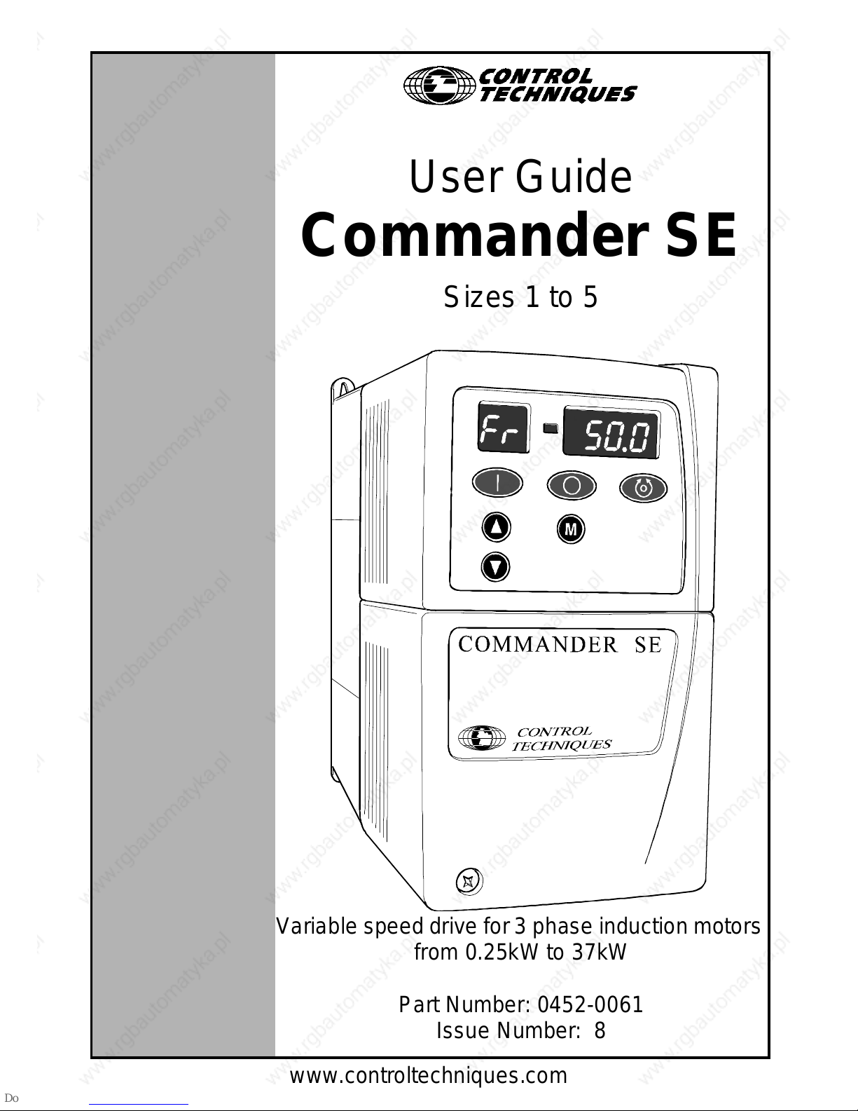
User Guide
Commander SE
Sizes 1 to 5
Variable speed drivefor 3 phase induction motors
from 0.25kW to 37kW
Part Number: 0452-0061
Issue Number: 8
Page 4

General Information
The manufacturer accepts no liability for anyconsequences resultingfrom inappro-
priate, negligent or incorrect installation or adjustment of the optional operating pa-
rameters ofthe equipment orfrom mismatching the variable speed drive (Drive) with
the motor.
The contentso f thisUser Guide are believed tobe correctat the time ofprinting. In
the interests of a commitment to a policy of continuous development and improve-
ment,themanufacturerreservestheright to changethespecificationof theproduct
or its performance, or the contents of the User Guide, withoutnotice.
All rights reserved. No parts of this User Guide may be reproduced or transmitted
in any form or by any means, electrical or mechanical including photocopying, re-
cording or by an information storage or retrievalsystem,without permissionin writ-
ing from the publisher.
Drive software version
Thisproductissuppliedwiththelatestversionofuser-interfaceandmachinecontrol
software. If this product is to be used in a new or existing system with other Com-
manderSE Drives,there may be some differences between their software and t he
software in this product. These differences may cause this product to function dif-
ferently. Thismay also applyto Drives returnedfroma Control TechniquesService
Centre.
If there is any doubt, contact a ControlTechniques Drive Centre.
Copyright © December 2001 Control Techniques Drives Limited
Issue Code: 8
Software: V02.00.00 onwards
Page 5
Commander SE User Guide
Issue Number 8
Contents
1 Safety Inform ation 1
1.1 Warnings, Cautions and notes 1
1.2 Electrical safety - general warning 1
1.3 System design and safety of personnel 1
1.4 Environmental limits 2
1.5 Compliance with regulations 2
1.6 Motor 2
1.7 Adjusting parameters 2
2Options 3
3 Technical Data 4
3.1 Power dependant ratingdata 4
3.2 Generaldata 12
3.3 RFI Filters 14
4 Installing the drive 16
4.1 Safety information 16
4.2 Planning the installation 16
4.3 Mechanical installation 17
4.4 Electrical installation 23
4.5 Electromagnetic compatibility (EMC) 27
5 Terminals 34
5.1 Power terminal connections 34
5.2 Control terminal connections 35
5.3 Serial communication connections 36
5.4 Control terminal specifications 37
6 Handling and Programming 40
6.1 Display and keypad 40
6.2 Display Messages 41
6.3 Selecting and changing parameters 41
6.4 Saving parameters 42
6.5 Security codes 42
6.6 Setting a security code 42
6.7 Unlocking a security code 43
6.8 Set security back to zero ( 0) - no security 43
6.9 Setting to default values 43
6.10 Level1 and level 2 parameter descriptions 43
7 Getting Started - Bench T esting 61
7.1 Terminal control 61
7.2 Keypad control 63
8 Diagnostics and Protective Features 65
8.1 Trip codes 65
8.2 Alarm warnings 67
8.3 HF-Hardware fault tripcodes 67
Page 6
Commander SE User Guide
Issue Number8
9 Parameter List 68
10 Advanced Functions 69
10.1 Speed control 69
10.2 Ramps 69
10.3 Torque control 69
10.4 Stopping 69
10.5 Programmable I/O 69
10.6 Motor protection 69
10.7 Monitoring 69
10.8 Auxiliary functions 69
10.9 Second motor selection 69
11 UL Listing Information 70
11.1 Common UL information 70
11.2 Power dependantUL information 70
Page 7
Commander SE User Guide
Issue Number 8
Declaration of Conformity
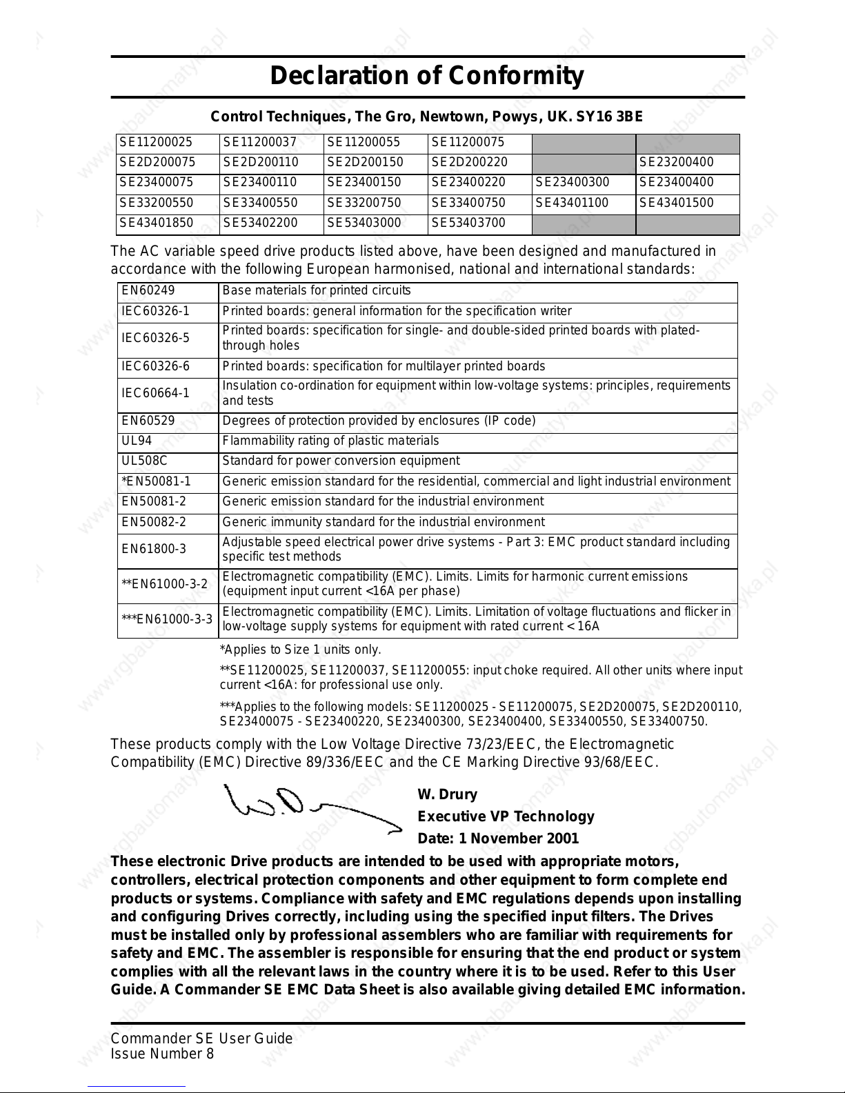
Control Techniques, The Gro, Newtown, Powys, UK. SY16 3BE
The AC variable speed drive products listed above, have been designed and manufactured in
accordance with the following European harmonised, national and international standards:
*Applies to Size 1 units only.
**SE11200025, SE11200037, SE11200055: input choke required. All other units where input
current <16A: for professional use only.
***Applies to the followingmodels:SE11200025 - SE11200075, SE2D200075, SE2D200110,
SE23400075 - SE23400220, SE23400300, SE23400400, SE33400550, SE33400750.
These productscomplywith the Low Voltage Directive 73/23/EEC,the Electromagnetic
Compatibility (EMC)Directive 89/336/EEC and the CE Marking D irective93/68/EEC.
These electronic Drive products are intended to be used with appropriate motors,
controllers, electrical protection components and other equipment to form complete end
products or systems. Compliance with safety and EMC regulations depends upon installing
and configuring Drives correctly, including using the specified input filters. The Drives
must be installed only by professional assemblers who are familiar with requirements for
safety and EMC. The assembler is responsible for ensuring that t he end product or system
complieswithalltherelevantlawsinthecountrywhereitistobeused.RefertothisUser
Guide.A Commander SE EMC Data Sheet is also available giving detailed EMC information.
SE11200025 SE11200037 SE11200055 SE11200075
SE2D200075 SE2D200110 SE2D200150 SE2D200220 SE23200400
SE23400075 SE23400110 SE23400150 SE23400220 SE23400300 SE23400400
SE33200550 SE33400550 SE33200750 SE33400750 SE43401100 SE43401500
SE43401850 SE53402200 SE53403000 SE53403700
EN60249 Base materials for printed circuits
IEC60326-1 Printed boards: general information for the specification writer
IEC60326-5
Printed boards: specification for single- and double-sided printed boards with plated-
through holes
IEC60326-6 Printed boards: specification for multilayer printed boards
IEC60664-1
Insulation co-ordination for equipment within low-voltage systems: principles, requirements
and tests
EN60529 Degrees of protection provided by enclosures (IP code)
UL94 Flammability rating of plastic materials
UL508C Standard for power conversion equipment
*EN50081-1 Generic emission standard for the residential, commercial and light industrial environment
EN50081-2 Generic emission standard for the industrial environment
EN50082-2 Generic immunity standard for the industrial environment
EN61800-3
Adjustable speed electrical power drive systems - Part 3: EMC product standard including
specific test methods
**EN61000-3-2
Electromagnetic compatibility (EMC). Limits. Limits for harmonic current emissions
(equipment input current <16A per phase)
***EN61000-3-3
Electromagnetic compatibility (EMC). Limits. Limitation of voltage fluctuations and flicker in
low-voltage supply systems for equipment with rated current < 16A
W. Drury
Executive VP Technology
Date: 1 November 2001
Page 8
1 Commander SE User Guide
www.controltechniques.com Issue Number 8
1 Safety Information
1.1 Warnings, Cautions and notes
A Warnin g contains information which is essential for avoiding a safety hazard.
A
Caution contains information which is necessary for avoiding a risk o f damage to
the product or other equipment.
A
Note contains information which helps to ensure correct operation of the product.
1.2 Electrical safety - general warning
The voltages used in the drive can cause severe electrical shock and/or burns, and
could be lethal. Extreme care is necessary at all times when working with or adjacent to
the drive.
Specificwarnings are givenat the relevant places in this User Guide.
1.3 System design and safety of personnel
The driveis intended as a component for professional incorporation into complete
equipment or a system. If installed incorrectly, the drivemay present a safety hazard.
The driveuses highvoltage and currents, carries a high level of storedelectrical energy,
and is used to control equipment whichcan cause injury.
Close attention is requiredto the electrical installation and the system design to avoid
hazards, either in normal operat ion or in the event of equipment malfunction. System
design, installation, commissioning and maintenance mustbe carried out by personnel
whohave the necessarytraining and experience. They must readthissafety information
and this User Guide carefully.
The STOP function of the drive does not remove dangerousvoltages fromthe outputof
the drive or from any external option unit.
Careful consideration must be given to the functions of the drive which might result in a
hazard, either through their intended functions or through incorrect operation due to a
fault.
In any application where a malfunction of the drive could lead to damage,loss or injury,
a risk analysis must be carried out,and where necessary, further measures takento
reduce the risk.
The STOP and START controls or electrical inputs of the drive must not be relied
upon to ensure safety of personnel. If a safety hazard could exist from
unexpected starting of the drive, an interlock that electrically isolates the drive
from the AC supply must be installed to prevent the motor being inadvertently
started.
To ensure mechanical safety, additional safetydevices such as electro-mechanical
interlocks and overspeed protection devices may be required. The drive must not be
used in a safety critical application without additional high integrity protectionagainst
hazards arising from a malfunction.
Under certainconditions, the drive can suddenly discontinue control of the motor. If t he
load on themotor could cause the motor speed to be increased (e.g. in hoists and
cranes), a separate method of braking and stopping must be used (e.g. a mechanical
brake).
WARNING
CAUTION
NOTE
Page 9
Commander SE User Guide 2
Issue Number 8 www.controltechniques.com
1.4 Environmental limits
Instructions in this User Guide regarding transport, storage, installation and use of the
drive must be complied with, including the specified environmental limits. Drives must
not be subjected to excessive physical force.
1.5 Compliance with regulations
The installer is responsible for complying with all relevant regulations, such as national
wiringregulations, accidentprevention regulations and electromagnetic compatibility
(EMC) regulations. Particular attention must be given to the cross-sectional areas of
conductors, the selection of fuses or otherprotection, and protective earth (ground)
connections.
This User Guide contains instruction for achieving compliance with specific EMC
standards.
Within the European Union, all machinery in which this product is used must comply
with the following directives:
• 97/37/EC: Safety of machinery.
• 89/336/EEC: Electromagnetic Compatibility.
1.6 Motor
Ensurethe motor is installed in accordance with the manufacturer’s recommendations.
Ensure the motor shaftis not exposed.
Standard squirrel cage induction motors are designed for single speed operation. If it is
intended t o use the capability of the driveto run a motor at speeds above its designed
maximum, it is strongly recommended that the manufacturer is consulted first.
Low speeds may cause the motor to overheat because the cooling fan becomes less
effective. The motor should be fitted with a protection thermistor. If necessary , an
electric forced vent fan should be used.
1.7 Adjusting parameters
Some parameters have a profound effect on the operation of the drive. They must not
be altered without careful consideration of the impact on the controlled system.
Measures must be taken to prevent unwanted changes due to error or tampering.
Page 10
3 Commander SE User Guide
www.controltechniques.com Issue Number 8
2Options
The following options are available for Commander SE;
• Quickey for rapid parametertransfer (SE55)
• Standard and low earth leakage footprint / side mounting RFI filters andlow cost
panel mounting RFI filters
• UniversalKeypad, IP65, hand held or door mounting plain t ext, LCD display
•SESoftWindows
™ based set-upsoftware for advanced programming
• +10V to -10V analog input card for bi-directional input reference (SE51)
• Cable screening bracket and screening clamps to provide a convenient way of
connecting supply, motor and control cable screens to ground (SE11, 12, 13, 14 &
15) (SE15 for Size 5 control cables only)
• EMC Data Sheets
• Through hole mounting plate drawings to allow heatsink to be put outside main
cubicle (Size 2 ~ 4 only)
• EIA232 to EIA485(2 wire) converterfor connecting betweenthe driveandPC when
using SE Soft (SE71 Communications lead)
• Fieldbus C ommunications:
Profibus DP (SE73)
Device Net (SE77)
CAN Open (SE77)
Interbus (SE74)
• Commander SE Advanced User Guide: (See Chapter 10 Advanced Functions on
page 69 for a list of advanced functions).
• AC input line r eactors
• Braking r esistors and mounting plate (Size 2 ~ 4 only)
For f urther details on the above options and availability, contact your local Control
Techniques Drive Centre or Distributor.
Page 11
Commander SE User Guide 4
Issue Number 8 www.controltechniques.com
3 Technical Data
3.1 Power de pendant rating data
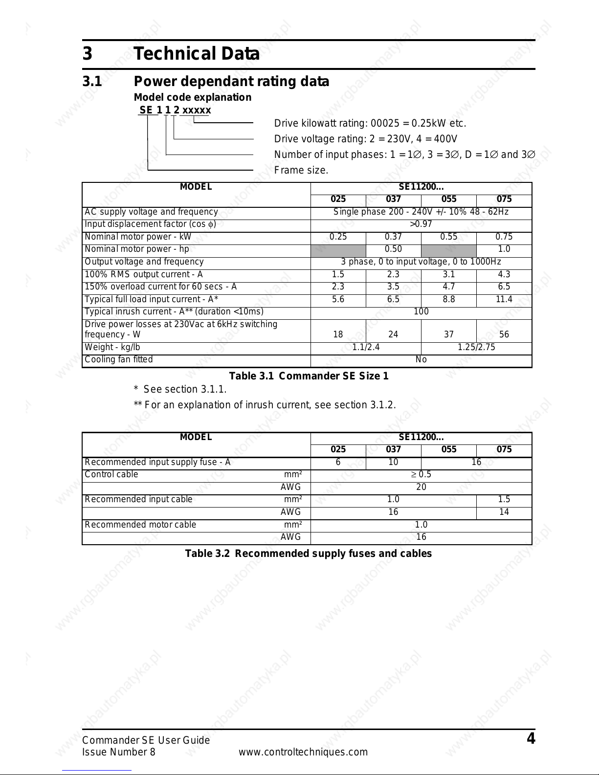
Model code explanation
SE 1 1 2 xxxxx
Drivekilowatt rating:00025 = 0.25kW etc.
Drive voltage rating: 2 = 230V, 4 = 400V
Number of input phases: 1 = 1∅,3=3∅,D=1∅ and 3∅
Frame size.
Table 3.1 Commander SE Size 1
* Seesection 3.1.1.
** For an explanation of inrush current, see section 3.1.2.
Table 3.2 Recommended supply fuses and cables
MODEL SE11200...
025 037 055 075
AC supply voltage and frequency Single phase 200 - 240V +/- 10% 48 - 62Hz
Input displacement factor (cos φ) >0.97
Nominal motor power - kW 0.25 0.37 0.55 0.75
Nominal motor power - hp
0.50 1.0
Output voltage and frequency 3 phase, 0 to input voltage, 0 to 1000Hz
100% RMS output current - A 1.5 2.3 3.1 4.3
150% overload current for 60 secs - A 2.3 3.5 4.7 6.5
Typical full load input current - A* 5.6 6.5 8.8 11.4
Typical inrush current - A** (duration <10ms) 100
Drive power losses at 230Vac at 6kHz switching
frequency - W 18 24 37 56
Weight - kg/lb 1.1/2.4 1.25/2.75
Cooling fan fitted No
MODEL SE11200...
025 037 055 075
Recommended input supply fuse - A 6 10 16
Control cable mm² ≥ 0.5
AWG 20
Recommended input cable mm² 1.0 1.5
AWG 16 14
Recommended motor cable mm² 1.0
AWG 16
Page 12
5 Commander SE User Guide
www.controltechniques.com Issue Number 8
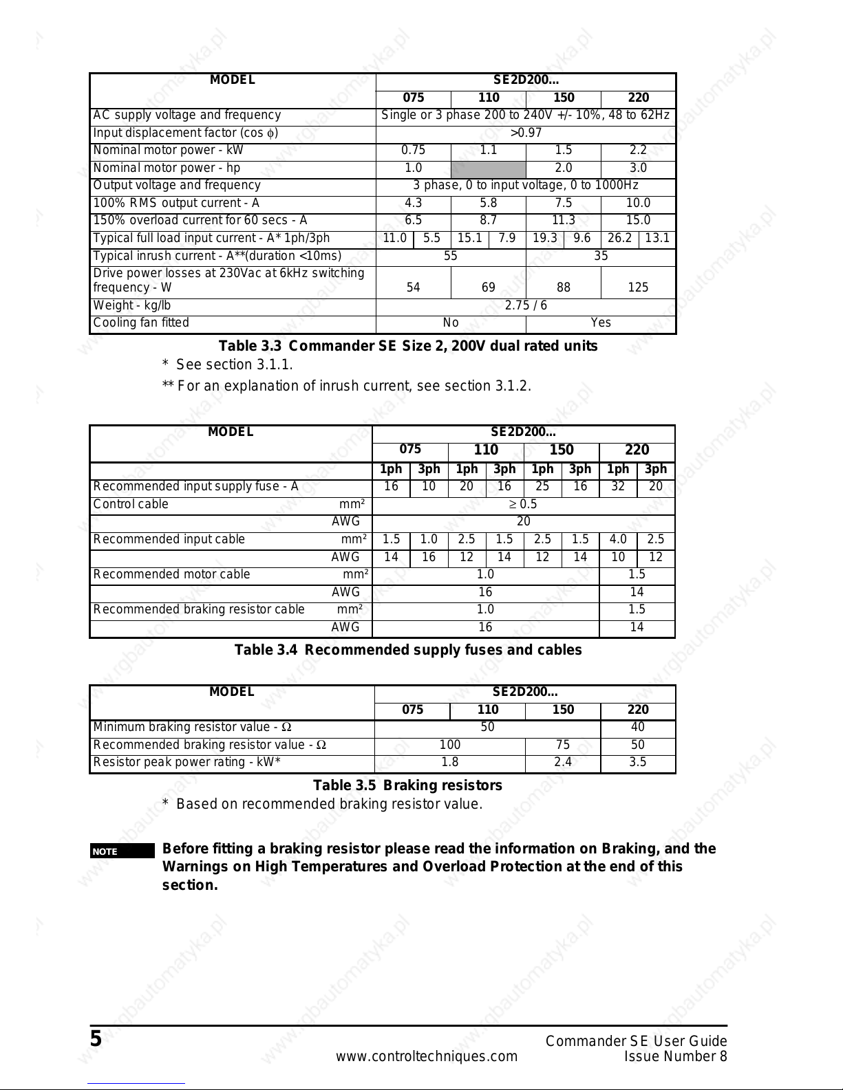
Table 3.3 Commander SE Size 2, 200V dual rated units
* See section 3.1.1.
** For an explanation of inrush current, see section 3.1.2.
Table 3.4 Recommended supply fuses and cables
Table 3.5 Braking resistors
* Based on recommended braking resistor value.
Before fitting a braking resistor please read the information on Braking, and the
Warnings on High Temperatures and Overload Protection at the end of this
section.
MODEL SE2D200...
075 110 150 220
AC supply voltage and frequency Single or 3 phase 200 to 240V +/- 10%, 48 to 62Hz
Input displacement factor (cos φ) >0.97
Nominal motor power - kW 0.75 1.1 1.5 2.2
Nominal motor power - hp 1.0
2.0 3.0
Output voltage and frequency 3 phase, 0 to input voltage, 0 to 1000Hz
100% RMS output current - A 4.3 5.8 7.5 10.0
150% overload current for 60 secs - A 6.5 8.7 11.3 15.0
Typical full load input current - A* 1ph/3ph 11.0 5.5 15.1 7.9 19.3 9.6 26.2 13.1
Typical inrush current - A**(duration <10ms) 55 35
Drive power losses at 230Vac at 6kHz switching
frequency - W 54 69 88 125
Weight - kg/lb 2.75 / 6
Cooling fan fitted No Yes
MODEL SE2D200...
075
110 150 220
1ph 3ph 1ph 3ph 1ph 3ph 1ph 3ph
Recommended input supply fuse - A 16 10 20 16 25 16 32 20
Control cable mm² ≥ 0.5
AWG 20
Recommended input cable mm² 1.5 1.0 2.5 1.5 2.5 1.5 4.0 2.5
AWG1416121412141012
Recommended motor cable mm² 1.0 1.5
AWG 16 14
Recommended braking resistor cable mm² 1.0 1.5
AWG 16 14
MODEL SE2D200...
075 110 150 220
Minimum braking resistor value - Ω 50 40
Recommended braking resistor value - Ω 100 75 50
Resistor peak power rating - kW* 1.8 2.4 3.5
NOTE
Page 13
Commander SE User Guide 6
Issue Number 8 www.controltechniques.com
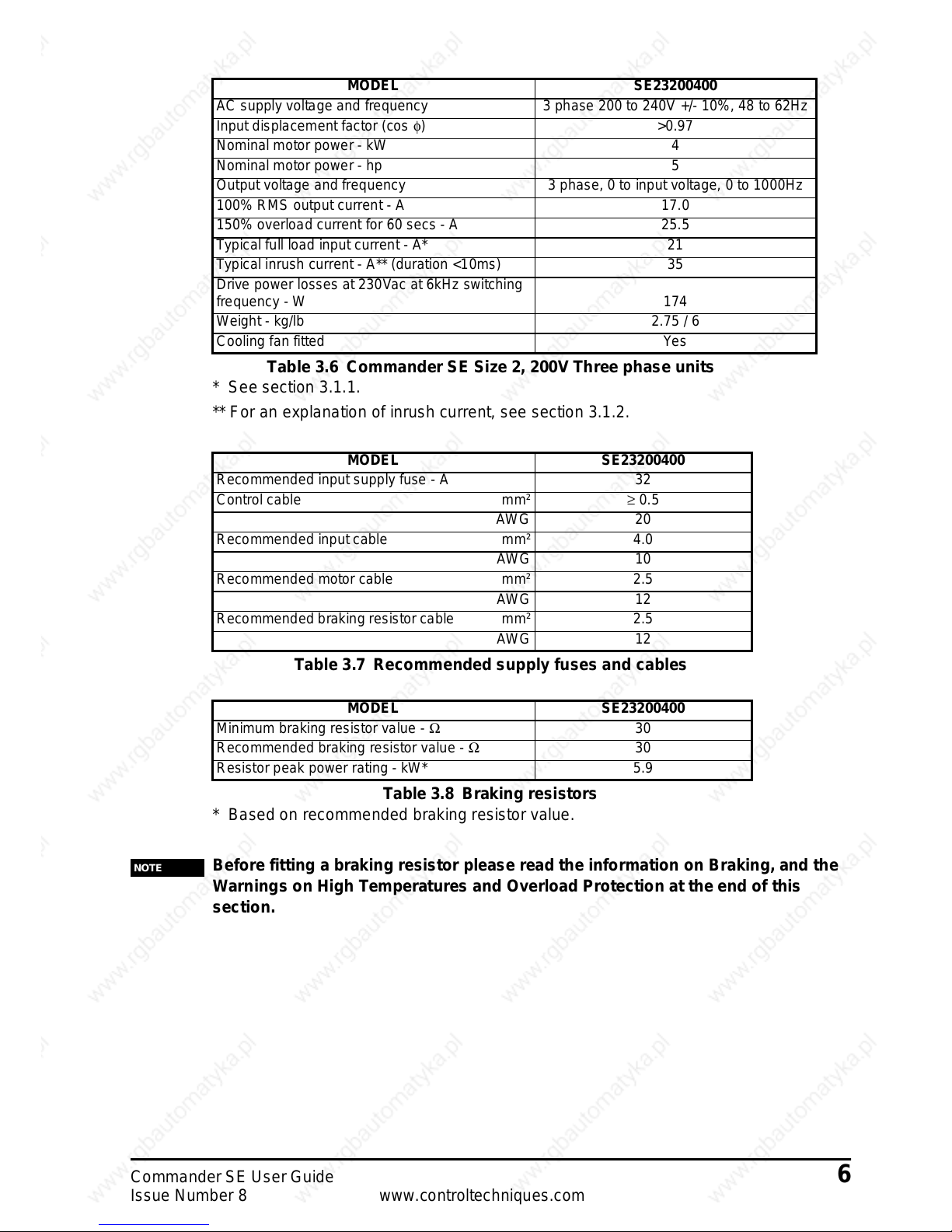
Table 3.6 Commander SE Size 2, 200VThree phase units
* Seesection 3.1.1.
** For an explanation of inrush current, see section 3.1.2.
Table 3.7 Recommended supply fuses and cables
Table 3.8 Braking resistors
* Based on recommended brakingresistor value.
Before fitting a braking resistor please read the information on Braking, and the
Warnings on High Temperatures and Overload Protection at the end of this
section.
MODEL SE23200400
AC supply voltage and frequency 3 phase 200 to 240V +/- 10%, 48 to 62Hz
Input displacement factor (cos φ) >0.97
Nominal motor power - kW 4
Nominal motor power - hp 5
Output voltage and frequency 3 phase, 0 to input voltage, 0 to 1000Hz
100% RMS output current - A 17.0
150% overload current for 60 secs - A 25.5
Typical full load input current - A* 21
Typical inrush current - A** (duration <10ms) 35
Drive power losses at 230Vac at 6kHz switching
frequency - W 174
Weight - kg/lb 2.75 / 6
Cooling fan fitted Yes
MODEL SE23200400
Recommended input supply fuse - A 32
Control cable mm² ≥ 0.5
AWG 20
Recommended input cable mm² 4.0
AWG 10
Recommended motor cable mm² 2.5
AWG 12
Recommended braking resistor cable mm² 2.5
AWG 12
MODEL SE23200400
Minimum braking resistor value - Ω 30
Recommended braking resistor value - Ω 30
Resistor peak power rating - kW* 5.9
NOTE
Page 14
7 Commander SE User Guide
www.controltechniques.com Issue Number 8
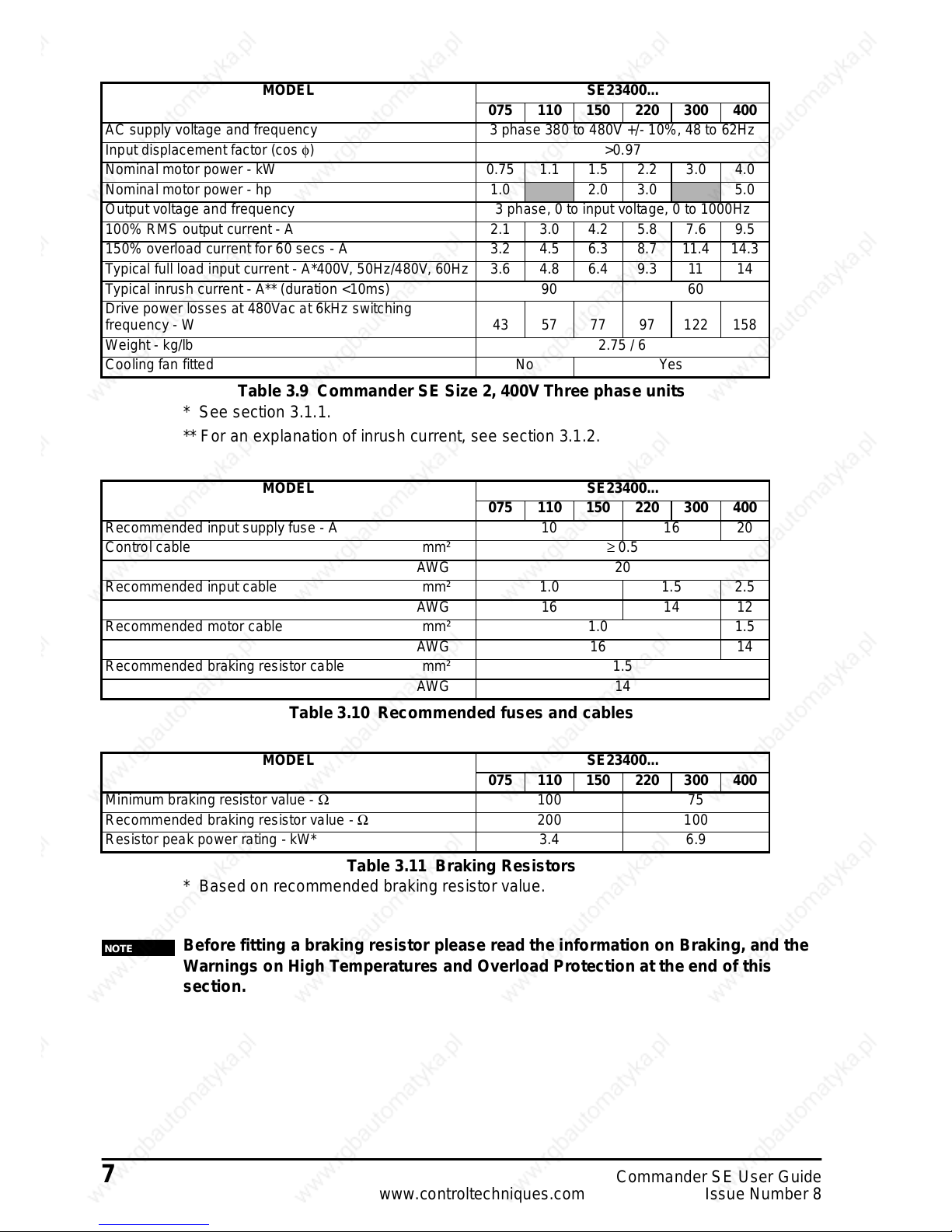
Table 3.9 Commander SE Size 2, 400V Three phase units
* See section 3.1.1.
** For an explanation of inrush current, see section 3.1.2.
Table 3.10 Recommended fuses and cables
Table 3.11 Braking Resistors
* Based on recommended braking resistor value.
Before fitting a braking resistor please read the information on Braking, and the
Warnings on High Temperatures and Overload Protection at the end of this
section.
MODEL SE23400...
075 110 150 220 300 400
AC supply voltage and frequency 3 phase 380 to 480V +/- 10%, 48 to 62Hz
Input displacement factor (cos φ) >0.97
Nominal motor power - kW 0.75 1.1 1.5 2.2 3.0 4.0
Nominal motor power - hp 1.0
2.0 3.0 5.0
Output voltage and frequency 3 phase, 0 to input voltage, 0 to 1000Hz
100% RMS output current - A 2.1 3.0 4.2 5.8 7.6 9.5
150% overload current for 60 secs - A 3.2 4.5 6.3 8.7 11.4 14.3
Typical full load input current - A*400V, 50Hz/480V, 60Hz 3.6 4.8 6.4 9.3 11 14
Typical inrush current - A** (duration <10ms) 90 60
Drive power losses at 480Vac at 6kHz switching
frequency - W 43 57 77 97 122 158
Weight - kg/lb 2.75 / 6
Cooling fan fitted No Yes
MODEL SE23400...
075 110 150 220 300 400
Recommended input supply fuse - A 10 16 20
Control cable mm² ≥ 0.5
AWG 20
Recommended input cable mm² 1.0 1.5 2.5
AWG 16 14 12
Recommended motor cable mm² 1.0 1.5
AWG 16 14
Recommended braking resistor cable mm² 1.5
AWG 14
MODEL SE23400...
075 110 150 220 300 400
Minimum braking resistor value - Ω 100 75
Recommended braking resistor value - Ω 200 100
Resistor peak power rating - kW* 3.4 6.9
NOTE
Page 15
Commander SE User Guide 8
Issue Number 8 www.controltechniques.com
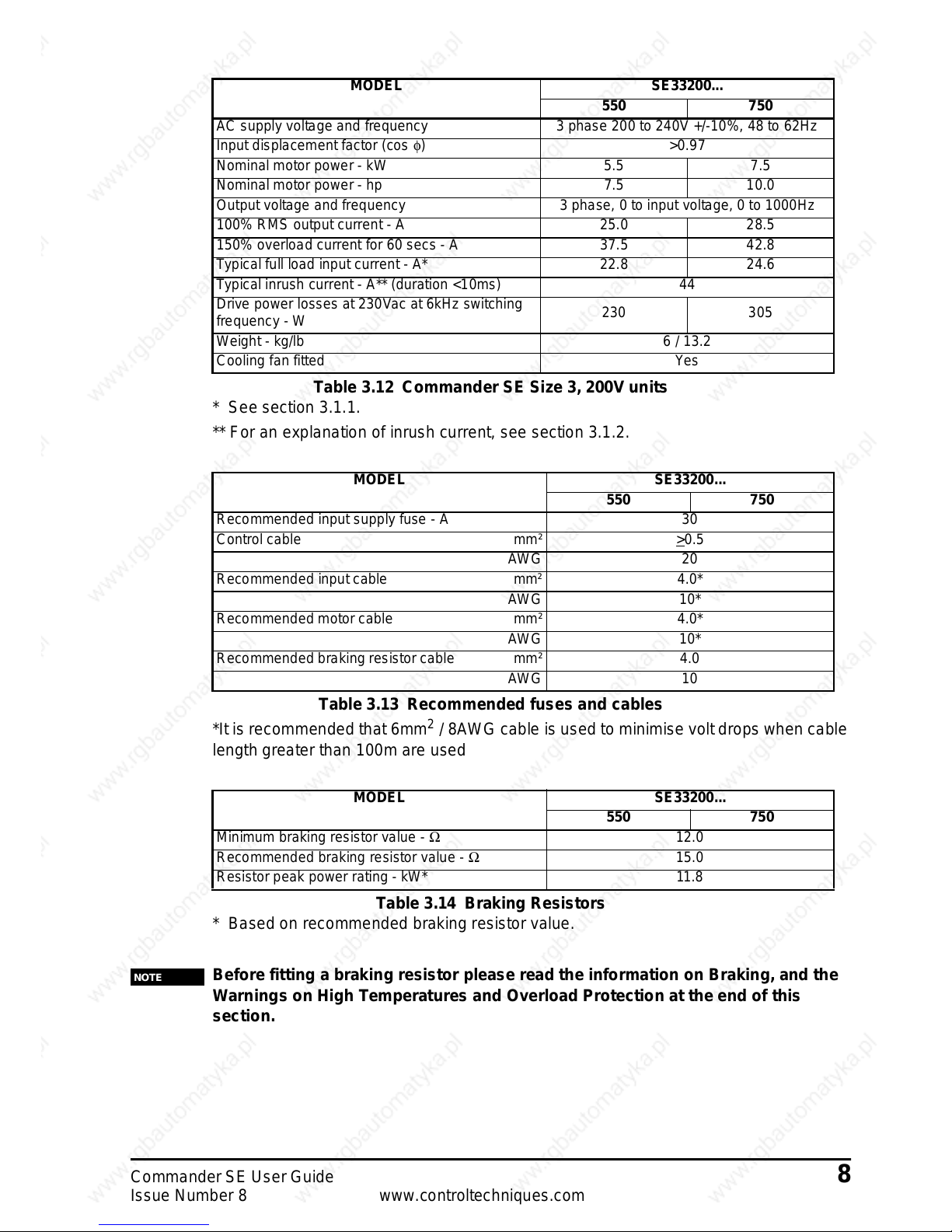
Table 3.12 Commander SE Size 3, 200V units
* Seesection 3.1.1.
** For an explanation of inrush current, see section 3.1.2.
Table3.13 Recommended fuses and cables
*It is recommended that6mm
2
/ 8AWG cable is used t o minimisevolt drops whencable
lengthgreaterthan 100m are used
Table 3.14 Braking Resistors
* Based on recommended brakingresistor value.
Before fitting a braking resistor please read the information on Braking, and the
Warnings on High Temperatures and Overload Protection at the end of this
section.
MODEL SE33200...
550 750
AC supply voltage and frequency 3 phase 200 to 240V +/-10%, 48 to 62Hz
Input displacement factor (cos φ)>0.97
Nominal motor power - kW 5.5 7.5
Nominal motor power - hp 7.5 10.0
Output voltage and frequency 3 phase, 0 to input voltage, 0 to 1000Hz
100% RMS output current - A 25.0 28.5
150% overload current for 60 secs - A 37.5 42.8
Typical full load input current - A* 22.8 24.6
Typical inrush current - A** (duration <10ms) 44
Drive power losses at 230Vac at 6kHz switching
frequency - W
230 305
Weight - kg/lb 6 / 13.2
Cooling fan fitted Yes
MODEL SE33200...
550 750
Recommended input supply fuse - A 30
Control cable mm² >
0.5
AWG 20
Recommended input cable mm² 4.0*
AWG 10*
Recommended motor cable mm² 4.0*
AWG 10*
Recommended braking resistor cable mm² 4.0
AWG 10
MODEL SE33200...
550 750
Minimum braking resistor value - Ω 12.0
Recommended braking resistor value - Ω 15.0
Resistor peak power rating - kW* 11.8
NOTE
Page 16
9 Commander SE User Guide
www.controltechniques.com Issue Number 8
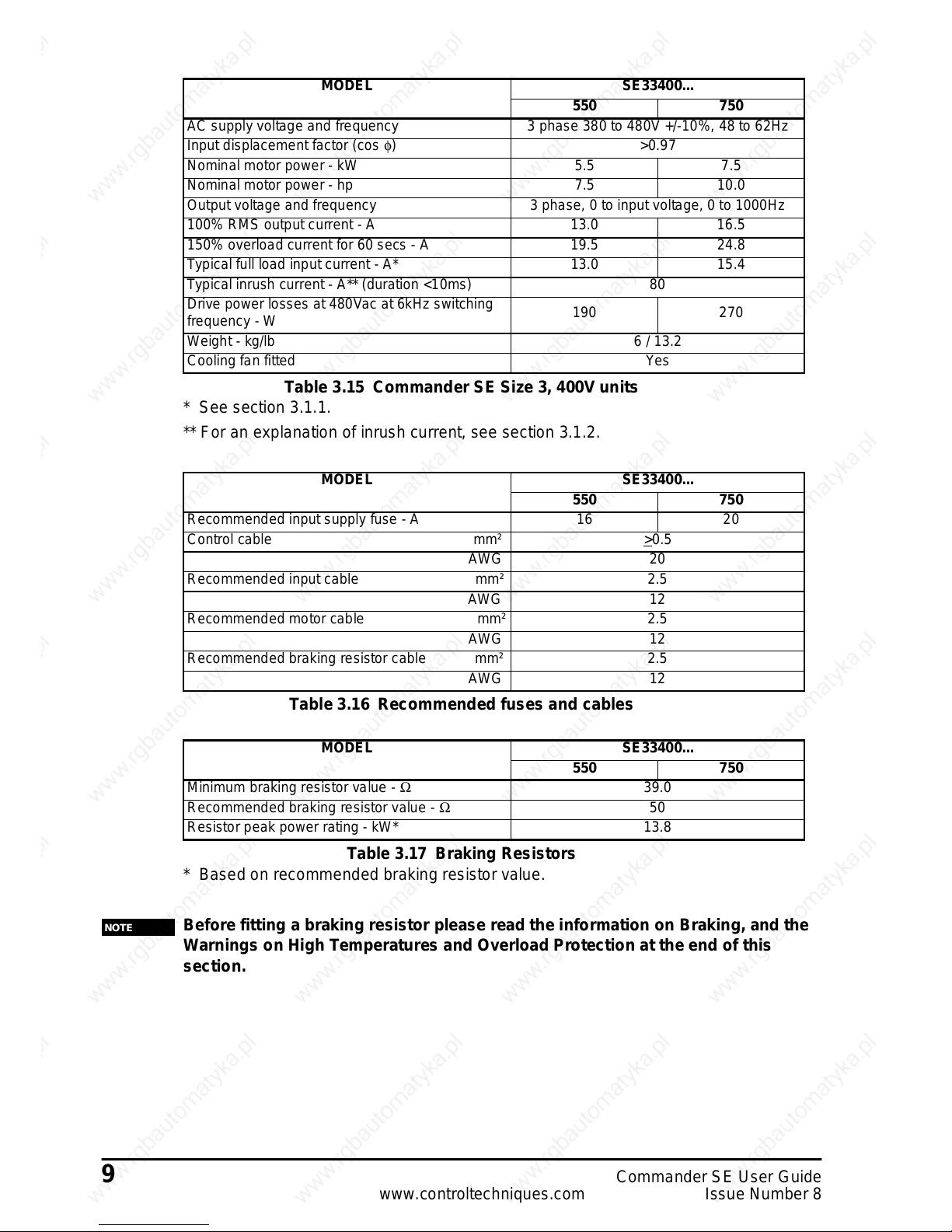
Table 3.15 Commander SE Size 3, 400V units
* See section 3.1.1.
** For an explanation of inrush current, see section 3.1.2.
Table 3.16 Recommended fuses and cables
Table 3.17 Braking Resistors
* Based on recommended braking resistor value.
Before fitting a braking resistor please read the information on Braking, and the
Warnings on High Temperatures and Overload Protection at the end of this
section.
MODEL SE33400...
550 750
AC supply voltage and frequency 3 phase 380 to 480V +/-10%, 48 to 62Hz
Input displacement factor (cos φ)>0.97
Nominal motor power - kW 5.5 7.5
Nominal motor power - hp 7.5 10.0
Output voltage and frequency 3 phase, 0 to input voltage, 0 to 1000Hz
100% RMS output current - A 13.0 16.5
150% overload current for 60 secs - A 19.5 24.8
Typical full load input current - A* 13.0 15.4
Typical inrush current - A** (duration <10ms) 80
Drive power losses at 480Vac at 6kHz switching
frequency - W
190 270
Weight - kg/lb 6 / 13.2
Cooling fan fitted Yes
MODEL SE33400...
550 750
Recommended input supply fuse - A 16 20
Control cable mm² >
0.5
AWG 20
Recommended input cable mm² 2.5
AWG 12
Recommended motor cable mm² 2.5
AWG 12
Recommended braking resistor cable mm² 2.5
AWG 12
MODEL SE33400...
550 750
Minimum braking resistor value - Ω 39.0
Recommended braking resistor value - Ω 50
Resistor peak power rating - kW* 13.8
NOTE
Page 17
CommanderSE User Guide 10
Issue Number 8 www.controltechniques.com
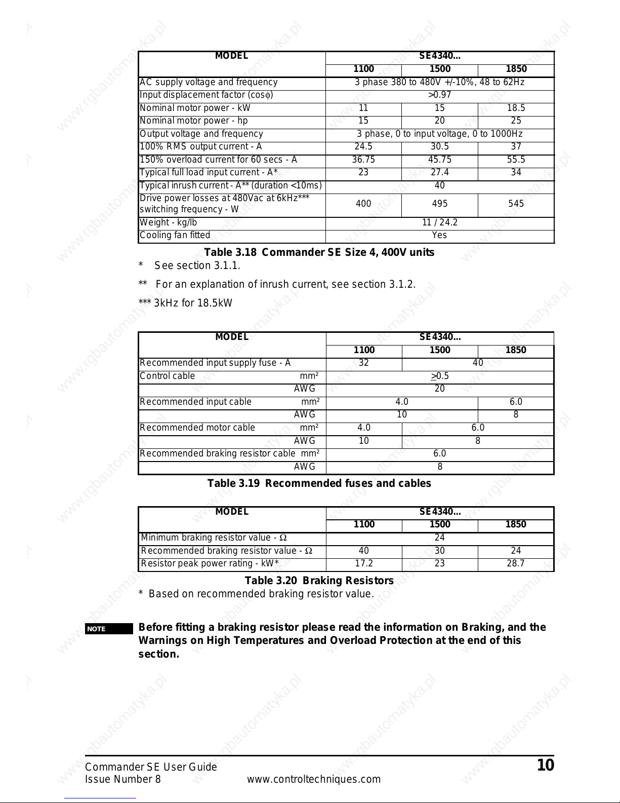
Table 3.18 Commander SE Size 4, 400V units
* See section 3.1.1.
** For an explanation of inrush current, see section 3.1.2.
*** 3kHz for 18.5kW
Table3.19 Recommended fuses and cables
Table 3.20 Braking Resistors
* Based on recommended brakingresistor value.
Before fitting a braking resistor please read the information on Braking, and the
Warnings on High Temperatures and Overload Protection at the end of this
section.
MODEL SE4340...
1100 1500 1850
AC supply voltage and frequency 3 phase 380 to 480V +/-10%, 48 to 62Hz
Input displacement factor (cosφ) >0.97
Nominal motor power - kW 11 15 18.5
Nominal motor power - hp 15 20 25
Output voltage and frequency 3 phase, 0 to input voltage, 0 to 1000Hz
100% RMS output current - A 24.5 30.5 37
150% overload current for 60 secs - A 36.75 45.75 55.5
Typical full load input current - A* 23 27.4 34
Typical inrushcurrent - A** (duration <10ms) 40
Drive power losses at 480Vac at 6kHz***
switching frequency - W
400 495 545
Weight - kg/lb 11/ 24.2
Cooling fan fitted Yes
MODEL SE4340...
1100 1500 1850
Recommended input supply fuse - A 32 40
Control cable mm² >
0.5
AWG 20
Recommended input cable mm² 4.0 6.0
AWG 10 8
Recommended motor cable mm² 4.0 6.0
AWG 10 8
Recommended braking resistor cable mm² 6.0
AWG 8
MODEL SE4340...
1100 1500 1850
Minimum braking resistor value - Ω 24
Recommended braking resistor value - Ω 40 30 24
Resistor peak power rating - kW* 17.2 23 28.7
NOTE
Page 18
11 Commander SE User Guide
www.controltechniques.com Issue Number 8
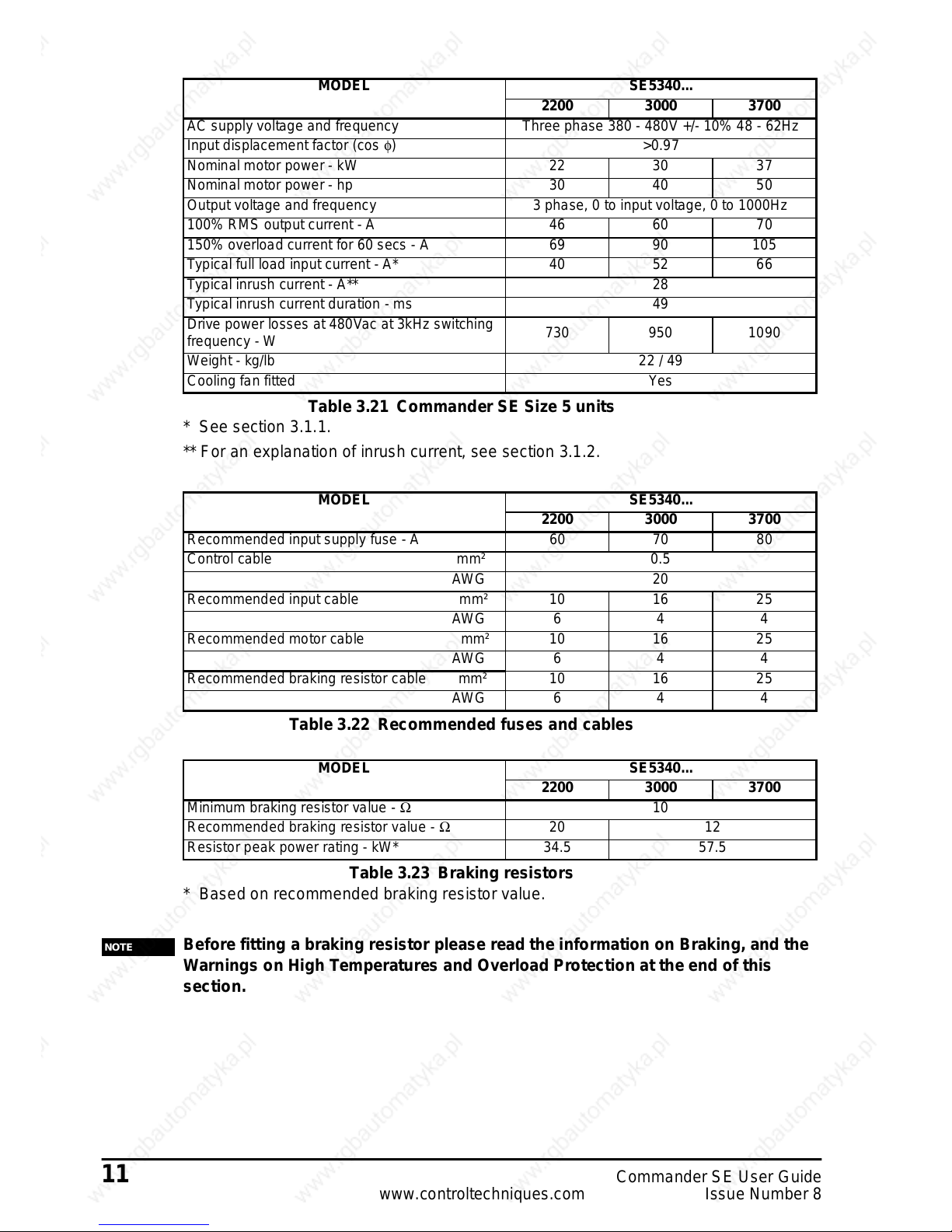
Table 3.21 Commander SE Size 5 units
* See section 3.1.1.
** For an explanation of inrush current, see section 3.1.2.
Table 3.22 Recommended fuses and cables
Table 3.23 Braking resistors
* Based on recommended braking resistor value.
Before fitting a braking resistor please read the information on Braking, and the
Warnings on High Temperatures and Overload Protection at the end of this
section.
MODEL SE5340...
2200 3000 3700
AC supply voltage and frequency Three phase 380 - 480V +/- 10% 48 - 62Hz
Input displacement factor (cos φ)>0.97
Nominal motor power - kW 22 30 37
Nominal motor power - hp 30 40 50
Output voltage and frequency 3 phase, 0 to input voltage, 0 to 1000Hz
100% RMS output current - A 46 60 70
150% overload current for 60 secs - A 69 90 105
Typical full load input current - A* 40 52 66
Typical inrush current - A** 28
Typical inrush current duration - ms 49
Drive power losses at 480Vac at 3kHz switching
frequency - W
730 950 1090
Weight- kg/lb 22/ 49
Cooling fan fitted Yes
MODEL SE5340...
2200 3000 3700
Recommended input supply fuse - A 60 70 80
Control cable mm² 0.5
AWG 20
Recommended input cable mm² 10 16 25
AWG 6 4 4
Recommended motor cable mm² 10 16 25
AWG 6 4 4
Recommended braking resistor cable mm² 10 16 25
AWG 6 4 4
MODEL SE5340...
2200 3000 3700
Minimum braking resistor value - Ω 10
Recommended braking resistor value - Ω 20 12
Resistor peak power rating - kW* 34.5 57.5
NOTE
Page 19
CommanderSE User Guide 12
Issue Number 8 www.controltechniques.com
Braking R esist ors - High Temperatures
Braking resistors can reach high temperatures. Locate braking resistors so that
damage cannot result. Use cable having insulation capable of withstanding high
temperatures.
Braking R esist ors - Overload Protection
It is essential that an overload protection device is incorporated in the braking
resistor circuit. This is described in section 5.1.1 Thermal Protection Circuit for
an Optional Braking Resistor.
3.1.1 *Input current
The inputcurrentvalues given could be exceeded where the supply faultcurrent is
greater than 5kA or the phase voltages are not balanced. In thesecases, input line
reactors are recommended. See section 4.4.3 Useoflinereactorson page 26.
3.1.2 **Temperature effects on inrush currents
Size1-4
Due t o the design ofthe inrushcircuit, the inrush currentwill be lower on the firstpower
up of the drive after a period of non-use and when the drive is cold. The inrush current
will increase when the time between power ups is short and the internal ambient
temperature within the drive is high.
3.2 General data
IP Rating
NEMA Enclosure Rating
WARNING
WARNING
Size 1: IP20
The Ingress Protection rating is applicable to the drive when
the supplied rubber grommetsare fittedinto the gland plate.
Sizes 2, 3 & 4: IP20
The IngressProtectionratingis applicable to t he drivewhen
the supplied rubber grommetsare fittedinto the gland plate
and the drive is mounted on a solid flat surface.
Size 5: IP00 - Gland plate not fitted
IP10 - Glandplate fitted, cable glandsnot fitted (unused holes
covered)
IP20 - Glandplate fitted, cable glands fitted(blanking caps
covering unused holes)
Size 1: The drive has a NEMA 1 enclosure ratingwhen a suitable
methodof cable entry is used, e.g. conduit
Sizes 2, 3 & 4: ThedrivehasaNEMA1enclosureratingwhenmountedona
solid flat surface and a suitable method of cable entry is used,
e.g. conduit
Size 5: ThedrivedoesnothaveaNEMA1enclosurerating.
NEMA1isanenclosureconstructedforindoorusetoprovideadegreeofprotectionto
personnel against incidental contact with the enclosed equipment and to providea
degree of protection against falling debris.
Page 20
13 Commander SE User Guide
www.controltechniques.com Issue Number 8
If the drive is not mounted as indicated, hazardous live parts will be exposed and
the IP Rating or NEMA 1 enclosure rating of the drive will be invalid.
WARNING
Input phase
imbalance:
Phase imbalance not to exceed 2% negative phase sequence
Ambient
temperature:
-10°Cto+40°C(14°Fto104°F) at 6kHz switchingfrequency.
-10°Cto+50°C(14°Fto122°F) at 3kHz switchingfrequency
with derating on somemodels.
-10°Cto+40°C(14°Fto104°F) at 3kHz switching frequency for
SE4, 18.5kW and SE Size 5.
See CommanderSE AdvancedUser Guide for Derating
Curves.
Storage temperature: -40°Cto+60°C (-40°Fto140°F) for12 monthsmax
Altitude: Reduce the normal full-load current by 1% for every 100m
(325ft) above 1000m (3250ft) to a maximum of 4000m
(13000ft).
Humidity: Maximum relativehumidity 95% (non-condensing)
Materials: Flammability rating of main enclosure :UL94-5VA (Size 1 to 4)
Flammability rating of main enclosure:UL94-V0 (Size 5)
Grommets:UL94-V1
Vibration (random):
Vibration
(sinusoidal)
Unpackaged - tested to 0.01g²/Hz (equivalent to 1.2g rms) from
5 to 150Hz for 1 hour in each of 3 axes in accordance with
IEC68-2-34 and IEC68-2-36.
Unpackaged - tested from 2-9Hz, 3.5mm displacement; 9-
200Hz 10m/s
2
acceleration; 200-500Hz, 15m/s2acceleration.
Duration - 15 minutes in each of 3 axes. Sweep rate 1 octave/
minute.
Test in accordancewith IEC68-2-6.
Bump: Packaged - tested to 40g, 6ms, 100 times/direction for all 6
direct ions as in IEC68-2-29
Unpackaged - tested to 25g, 6ms, 100 times/direction for all 6
directions in accordance with IEC68-2-29
Frequency
accuracy:
0.01%
Resolution: 0.1Hz
Output frequency
range:
0to1000Hz
Starts per hour: By using the electronic control terminals: Unlimited
By switching of the supply: 20 starts per hour maximum (3
minute intervals between starts)
Power up delay: 1.5 seconds maximum (Allow at least 1 second for Sizes 1 to 4
and 1.5 seconds for Size 5 before monitoring the state of the
status relay contacts, communicating with the drive via serial
communications etc.)
Page 21
CommanderSE User Guide 14
Issue Number 8 www.controltechniques.com
3.3 RFI Filters
RFI filters are available as optional extra parts where required.
Table 3.24 Commander SE Size 1
Table 3.25 Commander SE Size 2 - 200V, 26A, 1 phase
Table 3.26 Commander SE Size 2 - 200 / 400V, 16A, 3 phase
Table 3.27 Commander SE Size 2 - 200 / 400V, 16A, 3 phase
Serial
Communications:
2-wireEIA485 via RJ45 connector
ANSI and Modbus RTU protocols supported
Switching
Frequencies:
3, 6, and 12 kHz are available with Intelligent Thermal
Management software automatically changing the switching
frequenciesdepending on load conditions, heatsink
temperature and output frequency, to prevent heatsink
overtemperature trips.
EMC: EN50082-2 and EN61800-3for immunity
EN50081-1*, EN50081-2 and EN61800-3 first environment,
with optional RFI filter. See section 3.3 and section 4.5.
* Size 1 units only.
This is a product of the restricted distribution class
according to IEC61800-3.
In a domestic environment this product may c ause
radio interference in which case the user may be
required to take adequate measures.
WARNING
Used with Filter Part
No
Filter Type Mounting Max motor
cable length
(m)
Standard Low leakage Low cost Footprint Side
SE11200025 to
SE11200075
4200-6101 Y Y 20
4200-6102 Y Y Y 75
4200-6103 Y Y Y 15
Used with Filter Part
No
Filter Type Mounting Max motor
cable length
(m)
Standard Low leakage Low cost Footprint Side
SE2D200075 to
SE2D200220
4200-6201 Y Y Y 100
4200-6204 Y Y 50
4200-6205 Y Y Y 15
Used with Filter Part
No
Filter Type Mounting Max motor
cable length
(m)
Standard Low leakage Low cost Footprint Side
SE2D200075 to
SE2D200220
4200-6202 Y Y Y 100
4200-6304 Y Y 15
4200-6207 Y Y Y 45
Used with Filter Part
No
Filter Type Mounting Max motor
cable length
(m)
Standard Low leakage Low cost Footprint Side
SE23400075 to
SE23400400
4200-6202 Y Y Y 100
4200-6304 Y Y 15
4200-6207 Y Y Y 20
Page 22
15 Commander SE User Guide
www.controltechniques.com Issue Number 8
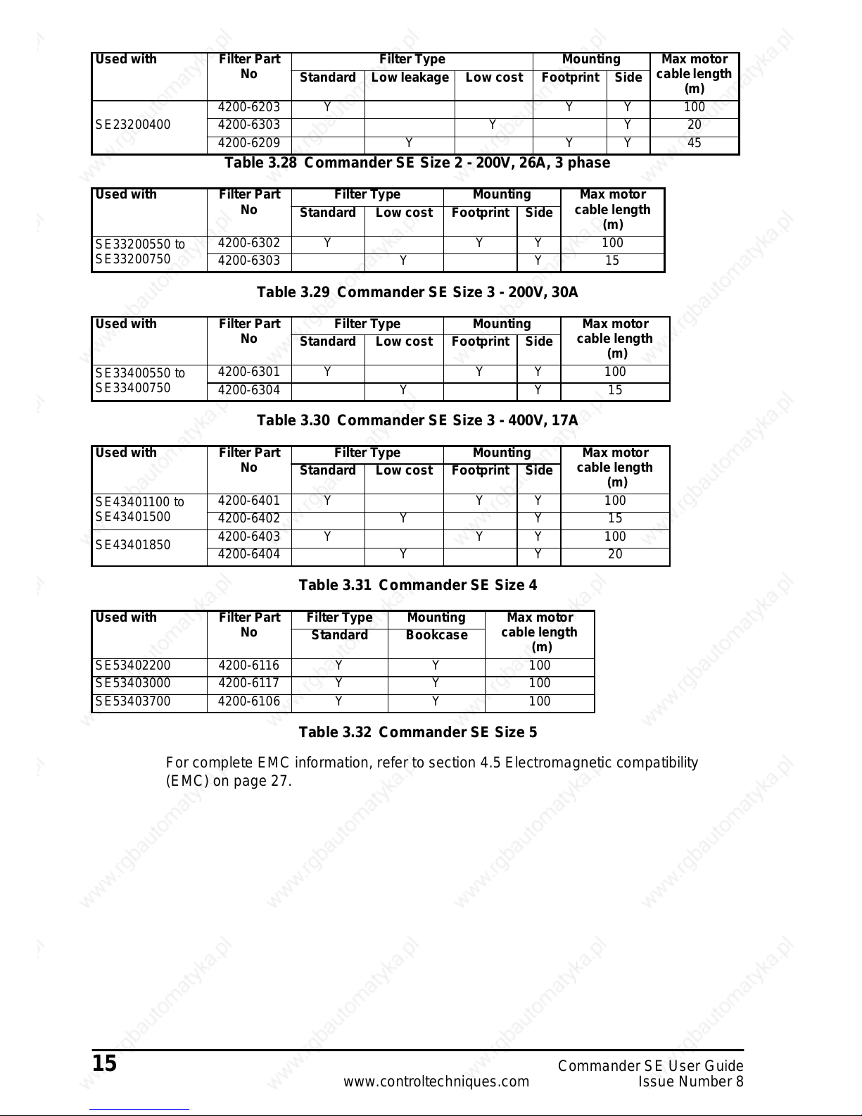
Table 3.28 Commander SE Size 2 - 200V, 26A, 3 phase
Table 3.29 Commander SE Size 3 - 200V, 30A
Table 3.30 Commander SE Size 3 - 400V, 17A
Table 3.31 Commander SE Size 4
Table 3.32 Commander SE Size 5
For complete EMC information, r efer to section 4.5 Electromagnetic compatibility
(EMC) on page 27.
Used with Filter Part
No
Filter Type Mounting Max motor
cable length
(m)
Standard Low leakage Low cost Footprint Side
SE23200400
4200-6203 Y Y Y 100
4200-6303 Y Y 20
4200-6209 Y Y Y 45
Used with Filter Part
No
Filter Type Mounting Max motor
cable length
(m)
Standard Low cost Footprint Side
SE33200550 to
SE33200750
4200-6302 Y Y Y 100
4200-6303 Y Y 15
Used with Filter Part
No
Filter Type Mounting Max motor
cable length
(m)
Standard Low cost Footprint Side
SE33400550 to
SE33400750
4200-6301 Y Y Y 100
4200-6304 Y Y 15
Used with Filter Part
No
Filter Type Mounting Max motor
cable length
(m)
Standard Low cost Footprint Side
SE43401100 to
SE43401500
4200-6401 Y Y Y 100
4200-6402 Y Y 15
SE43401850
4200-6403 Y Y Y 100
4200-6404 Y Y 20
Used with Filter PartNoFilter Type Mounting Max motor
cable length
(m)
Standard Bookcase
SE53402200 4200-6116 Y Y 100
SE53403000 4200-6117 Y Y 100
SE53403700 4200-6106 Y Y 100
Page 23
CommanderSE User Guide 16
Issue Number 8 www.controltechniques.com
4 Installing the drive
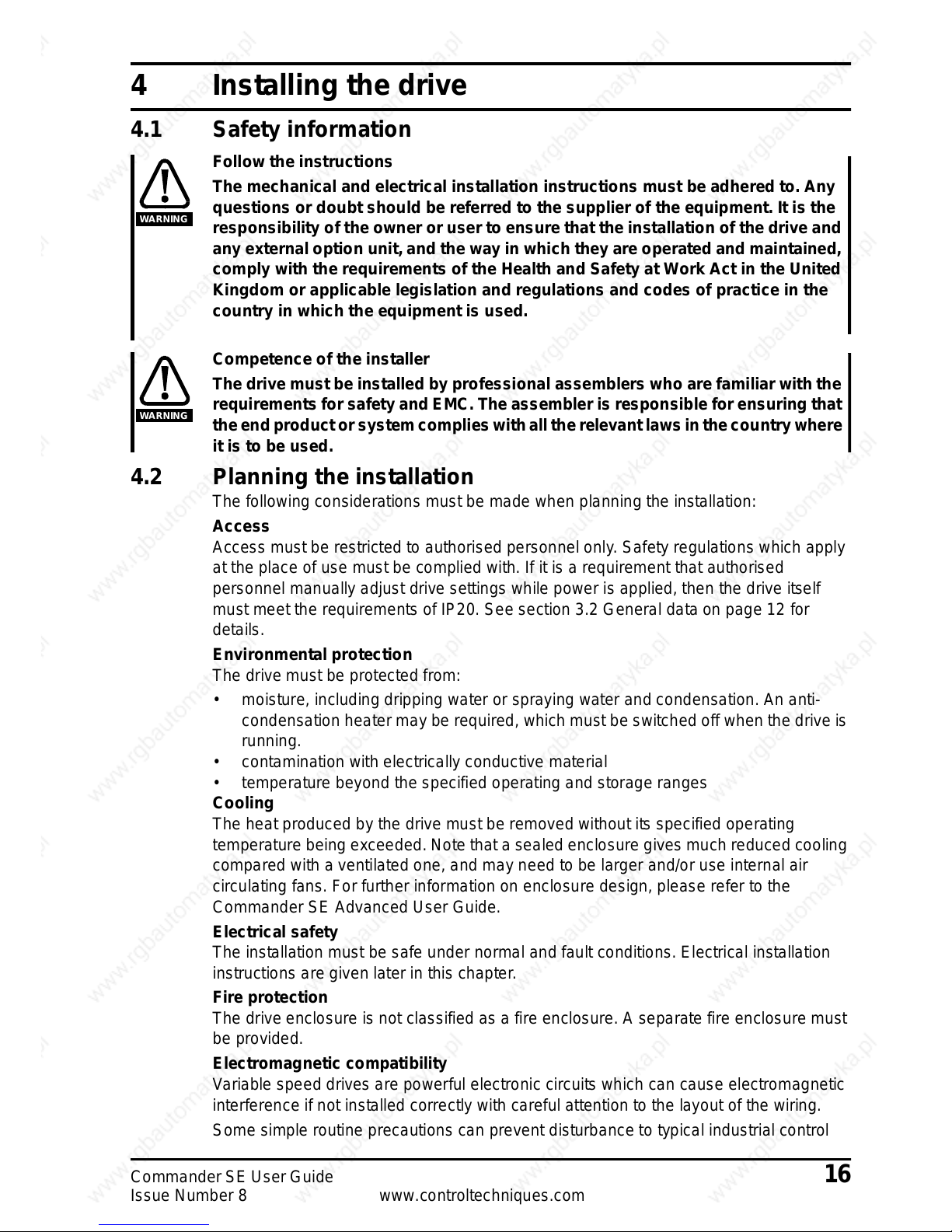
4.1 Safety information
Follow the instructions
The mechanical and electrical installation instructions must be adhered to. Any
questions or doubt should be referred to the supplier of the equipment. It is the
responsibility of the owner or user to ensure that the installation of the drive and
any external option unit, and the way in which they are operated and maintained,
comply with the requirements of the Health and Safety at Work Act in the United
Kingdom or applicable legislation and regulations and codes of practice in the
country in which the equipment is used.
Competence of the installer
The drive must be installed by professional assemblerswho are familiarwiththe
requirements for safety and EMC. The assembler is responsible for ensuring that
the end product or system complies with all the relevant laws in the country where
it is to be used.
4.2 Planning the installation
The following considerations must be made when planningthe installation:
Access
Access must be restricted to authorised personnel only. Safety regulations which apply
at the place of use must be complied with. If it is a requirement that authorised
personnel manually adjust drive settings while power is applied, t hen the drive itself
must meet the requirements of IP20. See section 3.2 General data on page 12 for
details.
Environmental protection
The drive must be protected from:
• moisture, including dripping water or spraying water and condensation. An anti-
condensation heatermay be required, whichmust be switchedoff whenthe driveis
running.
• contamination with electrically conductive material
• temperature beyond the specified operating and storage ranges
Cooling
The heat produced by the drive must be removedwithoutits specified operating
temperature being exceeded. Note that a sealed enclosure gives much reduced cooling
compared with a ventilated one, and may need to be larger and/or use internal air
circulating fans. For further information on enclosure design, please refer to the
Commander SE Advanced User Guide.
Electrical safety
The installation must be safe under normal and fault conditions. Electrical installation
instructions are given later in thischapter.
Fire protection
The drive enclosure is not classified as a fire enclosure. A separate fire enclosure must
be provided.
Electromagnetic compatibility
Variable speed drives are powerful electronic circuits which can cause electromagnetic
interference if not installed correctly with careful attention to the layout of the wiring.
Some simple routine precautions can prevent disturbance to typical industrial control
WARNING
WARNING
Page 24
17 Commander SE User Guide
www.controltechniques.com Issue Number 8
equipment.
If it is necessary to meet strictemission limits, or if it is knownthat electromagnetically
sensitive equipment is located nearby, then full precautions must be observed. These
willinclude the use of RFI filters at the drive i nputs, which must be locatedvery close to
the drives. Space must be made available for the filters and allowance made for
carefully segregated wiring. Both levels of precautions are given further on in this
chapter.
Hazardous areas
The drive must not be located in a classified hazardous areas unless it is installed in an
approved enclosure and the installation is certified.
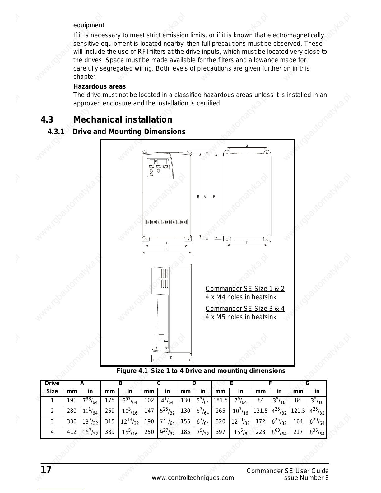
4.3 Mechanical installation
4.3.1 Drive and Mounting Dimensions
Figure 4.1 Size 1 to 4 Drive and mounting dimensions
C
D
F
B
EFA
G
Commander SE Size 1 & 2
4xM4holesinheatsink
Commander SE Size 3 & 4
4xM5holesinheatsink
Drive A B C D E F G
Size mm in mm in mm in mm in mm in mm in mm in
1 191
733/
64
175
6
57
/
64
102
4
1
/
64
130
5
7
/
64
181.5
7
9
/
64
84
3
5
/
16
84
3
5
/
16
2 280
11
1
/
64
259
10
3
/
16
147
5
25
/
32
130
5
7
/
64
265
10
7
/
16
121.5
4
25
/
32
121.5
4
25
/
32
3 336
13
7
/
32
315
12
13
/
32
190
7
31
/
64
155
6
7
/
64
320
12
19
/
32
172
6
25
/
32
164
6
29
/
64
4 412
16
7
/
32
389
15
5
/
16
250
9
27
/
32
185
7
9
/
32
397
15
5
/
8
228
8
63
/
64
217
8
35
/
64
Page 25

CommanderSE User Guide 18
Issue Number 8 www.controltechniques.com
Figure 4.2 Surface mounting Size 5 units
The drive should be mounted vertically. A mounting template is provided on the
drive packing cartonto aid installation.
When surface mounting a model size 5, allow a clearance of 150mm (6in) above
the drive; this is for dismounting. A minimum clearance of 100mm (4in) is
required for ventilation.
Figure 4.3 Through-panel mounting Size 5 units
Use M6 x 12mm max. (or equivalent) thread-forming screwsto screw into holes in the
heatsink, or tap the holes to a suitablethread size.
NOTE
Back-plate
13.189in 14.488in
1.772in
13.622in
6.890in
0.650in
0.650in
10.236in
7.382in
14.764in
375mm
187.5mm
335mm 368mm
260mm
16.5mm
16.5mm
346mm
175mm
45mm
NOTE
Back-plate
13.583in
0.650in
0.650in
11.299in
13.189in 14.331in
14.764in
10.236in
4.724in 5.512in
2.717in2.717in
5.177in 7.362in
14.094in
0.276in0.630
in
375mm
335mm 364mm
120mm
140mm
260mm
7mm 16mm
287mm
3
58mm
1
87mm
1
31.5mm
69mm 69mm
345mm
16.5mm
16.5mm
Page 26

19 Commander SE User Guide
www.controltechniques.com Issue Number 8
Table 4.1 Size 5 Mounting brackets
Figure4.4 Size5baffleplate
When a Commander SE size 5 is through-panel mounted a baffleplate is required to
ensurethe correct level of air flow is maintained through the heatsink. The fitting of a
baffle plate causes the heatsinkto act as a chimney; this enhancesthe air flow along
the heatsink fins to aid cooling (this naturallyoccurswhen the driveis surfacemounted).
You may make a baffle plate from any suitable conducting or non-conducting material.
Use M6 x 12mm max (or equivalent) thread-forming screws to screw into the holes in
the heatsink, or tap the holes to a suitable thread size.
Through-hole mounting
bracket
Surface mounting bracket
13.780in
3.583in 5.118in
0.276in
4.016in 7.697in
9.606in
=7mm
350mm
90mm
130mm
244mm
195.5mm102mm
Page 27

CommanderSE User Guide 20
Issue Number 8 www.controltechniques.com
4.3.2 CommanderSE standard and low earth leakage Footprint/Side mounting RF I
Filter:
Figure 4.5 RFI filter dimensions
* 60mm for Size 4, 18.5kW; 4200-6403
4.3.3 Commander SE Size 1 Low Cost RFI Filter mounting dimensions, 4200-6101.
Figure 4.6 Size 1 Low cost filter dimensions
D
F
C
ABE
Size1and2
Size3and4
8xM4holes
8xM5holes
for footprint mounting
Cable length
Earth stud: SE Size 1 - M4
SESize2~4-M5
Drive A B C D E F Cable Length
Size mm in mm in mm in mm in mm in mm in mm in
1242
9
17
/
32
195
7
43
/
64
100
3
15
/
16
40
1
37
/
64
225
8
7
/
8
80
3
5
/
32
190
7
31
/
64
2 330 13 281
11
1
/
16
148
5
13
/
16
45
1
49
/
64
313
12
21
/
64
122
4
51
/
64
250
9
27
/
32
3385
15
5
/
32
336
13
15
/
64
190
7
31
/
64
50
1
31
/
32
368
14
31
/
64
164
6
29
/
64
270
10
5
/
8
4467
18
25
/
64
414
16
19
/
64
246
9
11
/
16
55*
2
11
/
64
448
17
41
/
64
215
8
15
/
32
320
12
19
/
32
DC
AB
Cable length
230mm
∅
Z
M4
ABCDZ∅
mm in mm in mm in mm in mm in
113.5
4
15
/
32
103
4
1
/
16
58
2
9
/
32
45.5
1
51
/
64
4.4
3
/
16
Page 28

21 Commander SE User Guide
www.controltechniques.com Issue Number 8
4.3.4 Commander SE Size 2 and 3 Low cost single and three phase RFI Filter
mounting dimensions, 4200-6204 and 4200-6304.
Figure 4.7 RFI filter dimensions
4.3.5 Commander SE Size 2, 3 and 4 Low cost three phase R FI Filter mounting
dimensions, 4200-6303, 4200-6402 & 4200-6404.
Figure 4.8 RFI filter dimensions
Cable length
4200-6204 = 250mm
4200-6304 = 300mm
M5
∅
Z
ABCDEFG ∅ Z
mm in mm in mm in mm in mm in mm in mm in mm in
119
4
11
/
16
98.5
3
7
/
8
85.5
3
21
/
64
57.6
2
17
/
64
109
4
19
/
64
51 2 66
2
19
/
32
4.3x 7.5
3
/16x5/
16
A
B
C
D
E
F
G
H
Cable length
300mm
M5
Z
∅
ABCDEFG H∅ Z
mm in mm in mm in mm in mm in mm in mm in mm in mm in
4200-6303 133
515/
64
120
423/
32
118
441/
64
70
23/
4
80
35/
32
103
41/
16
90
335/
64
130.6
59/
64
6.5
1
/
4
4200-6402
4200-6404
143
55/
8
130
57/
64
128
51/
32
80
35/
32
80
35/
32
113
429/
34
100
315/
16
143
55/
8
6.5
1
/
4
Page 29

CommanderSE User Guide 22
Issue Number 8 www.controltechniques.com
4.3.6 SE53402200 bookcase mounted filter, 4200-6116
Figure 4.9 RFI filter dimensions
4.3.7 SE53403000 ~ SE53403700 bookcase mounted filter, 4200-6117, 4200-6106
Figure 4.10 RFI filter dimensions
C
F
A
B
D
E
G
A
B
C
D
E
F
G
4200-6117 = M6
4200-6106 = M8
ABCDEFG∅ Z
mm in mm in mm in mm in mm in mm in mm in mm in
4200-6116 337 13.27 259.5 10.22 90 3.54 100 3.94 275 10.83 50 1.97 290 11.42 7 0.28
4200-6117 377 14.84 300 11.81 150 5.9 103 4.05 315 12.4 105 4.13 330 12.99 7 0.28
4200-6106 380 14.96 294 11.57 150 5.9 107 4.21 310 12.2 105 4.13 325 12.79 7 0.28
Page 30

23 Commander SE User Guide
www.controltechniques.com Issue Number 8
4.3.8 Minimum Mounting Clearances
Figure 4.11 Minimum mounting clearances (applies to all drive sizes)
4.4 Electrical installation
Electric shock risk
Thevoltagespresentinthefollowinglocationscancausesevereelectricshock
and may be lethal:
• AC supply cables and connections
• Output cables and connections
• Many internal parts of the drive, and external option units
Isolation device
The AC supply must be disconnected from the drive using an approved isolation
device before any cover is removed from the drive or beforeany servicing work
is performed.
STOP function
The STOP function does not remove dangerous voltages from the drive or any
externaloption units.
Stored charge
The drive contains capacitors that remain charged t o a potentially lethal voltage
after the AC supply has been disconnected. If the drive has been energised, the
AC supply must be isolated at least ten minutes before work may continue.
Normally, the capacitors are discharged by an internal resistor. Under certain,
unusual fault conditions, it is possible that the capacitors may fail to discharge,
or be prevented from being discharged by a voltage applied to the output
terminals. If the drive has failed in a manner thatcauses the display to go blank
immediately, it is possible the capacitors will not be discharged. In this case,
consult Control Techniques or their authorised distributor.
1
8
1
8
100mm
(/in)
3
4
100mm
(/in)
3
4
10mm
(/in)
3
8
10mm
(/in)
3
8
20mm
(/in)
3
4
WARNING
WARNING
WARNING
WARNING
Page 31

CommanderSE User Guide 24
Issue Number 8 www.controltechniques.com
AC supply by plug and socket
Special attention must be given if the drive is installed in equipment which is
connected to the AC supply by a plug and socket. The AC supply terminals of the
drive a re connected to the internal capacitors through rectifier diodes which are
not intended to give safety isolation. If the plug terminals can be touched when
the plug is disconnected from the socket, a means of automatically isolating the
plug from the drive must be used (eg. a latching relay).
4.4.1 AC supply requirements
The following types of AC supply are suitable.
Single phase models:
• Single phase (i.e. between one phase and neutral of a star-connected three phase
supply)
• Between two phases of a three phase supply (any onephase can be grounded)
Three phase models:
• Three phase star or delta supply of the correct voltage (any one phase or neutral
can be grounded)
Dual rated 200V models:
• Any of the above
The input current differs for single phase and three phase supplies.
Supply voltageand currentinformation is given in Chapter 3 Technical Data.
4.4.2 Cables and fuses
Recommended cable sizes are given in Chapter 3 Technical Data. Theyare only a
guide. Refer to local wiring regulations for the correct size of cables. In some cases a
larger cable is required to avoid excessive voltage drop.
Use 105°C(221°F) (UL 60/75°C temp rise) pvc-insulated cable with copper conductors
having a suitable voltagerating,for the following power connections:
• AC supply to RFI filter (when used)
• AC supply (or RFI filter) to drive
•Drivetomotor
• Drive to braking resistor
Fuses
The AC supply to the drive must be fitted with suitable protection against
overload and short-circuits.The tables in Chapter 3 Technical Data show
recommended fuse ratings. Failure to observe this requirement will cause risk of
fire.
A fuse or other protection must be included in all live connections to the A C supply.
An MCB (miniaturecircuit breaker) or MCCB (moulded casecircuitbreaker) with type C
tripping characteristics and the same rating as the fuse(s), may be used in place of the
fuse(s), on condition that the fault current clearing capacity is sufficient for the
installation.
Fuse Types
Europe: Type gG fuses complying with EN60269parts 1 and 2.
USA: Bussman Limitron KTK series, class CC fast acting fuses.
Ground connections
The drive must be connected to the system groundof the AC supply. The ground wiring
must conform to local regulations and codes of practice.
WARNING
NOTE
WARNING
Page 32

25 Commander SE User Guide
www.controltechniques.com Issue Number 8
The ground loop impedance mustconform to the requirements of local safety
regulations. The ground connections must be inspectedand tested at appropriate
intervals.
Earth and ground leakage
Sizes 1 ~ 4
The drivehas a very small leakage current between the powerlines and ground, which
is of no consequence.
Size 5
Ground leakage currentis typically 9mA*. A fixed ground connection must be made
before the AC power is applied. In some applications,safety regulations require a
duplicate ground connection.
*9mA at 380V ac ~ 415V 50Hz AC supply. Measured by the method described in IEC950
Annex D.
The RFI filter has a higher leakage current, data is given in section 4.5.4, Tables
4.13 to 4.17. When the standard and low cost filters are used, a permanent fixed
ground connection must be provided which does not pass through a connector
or flexible power cord.
Motor cables
For routineEMC precautions
Use either of the following:
• Cables containing three power conductors plus a ground conductor
• Three separate power conductors plus a ground conductor
For full EMC precautions, where required (see section 4.5.2)
Use shielded (screened) or steel-wire armoured cable having three power conductors
plus a groundconductor.
If the cable between the drive and the motor is to be interrupted by a contactor or
circuit breaker, ensure that the drive is disabled before the contactor or circuit
breaker is opened or closed. Severe arcing may occur if this circuit is interrupted
with the motor running at high current and low speed.
Maximum motor cable lengths
The capacitiveloadingof the drive by the motorcablemeansthat the cablelengthlimits
shown in Table 4.2 must be observed. Failure to do so can result in spurious OI.AC
tripping of the drive. Iflongercable lengths are required,consultyour local DriveCentre
or Distributor.
The maximum cable lengths were measured using cable with capacitance of 412pF/m.
Table 4.2 Maximum motor cable lengths
* This cable length is f or 3kHz switching frequency.The cable length reduces in
proportionto the switching frequency; e.g. at 6kHz, it is reduced by a factorof 2 to 60m.
High Capacitance Cables
Most cables have an insulating jacket between the cores and the armour or shield;
these cables have a low capacitance and are recommended. Cables that do not have
WARNING
WARNING
WARNING
Drive Size Maximum motor cable length
Meters Feet
1 75 246
2 100 330
3 150 495
4 150 495
5 120* 394*
Page 33

CommanderSE User Guide 26
Issue Number 8 www.controltechniques.com
aninsulatingjackettend tohavehigh capacitance.
If a high capacitance cable is used, the maximum cable lengths in Table 4.2 should be
halved.
For further information please refer to the CommanderSE Advanced User Guide.
MultipleMotors
For advice on multiple motor applications where a number of small motors are
connected t o the output of one drive, please refer to the Commander SE Advanced
User Guide.
4.4.3 Use of line reactors
Linereactorscanbeusedtoreducesupplyharmonicsandalsoshouldbeusedifanyof
the following conditions apply:
• Supply capacity exceeds 200kVA
• Fault current exceeds 5kA
• Power-factor correction equipment is connected close to the drives
• Large DC drives having no or ineffective line reactors connected to the supply
• Direct on-line started motor(s) are connected to the supply and, when any of these
motors are started,a dip is produced in excess of 20% of the actual supply voltage
Duringanyof theaboveconditions, excessive peak current may flowin the inputbridge.
This may cause nuisancedrive tripping or, in extreme cases, failure of the input bridge.
A line reactorshould then be connected in each phaseof the supply to the input bridge.
Line reactor(s) add the required impedance to the AC supply in order to reduce current
transientstoa levelthatcan be tolerated bythe inputbridge. An impedance value of2%
is usually recommended.
Threeindividual reactors,or a single three-phase reactor should be used.Each network
of drivesmust have its own reactor(s).
RFI filters (for EMC purposes) do not give adequate protectionagainst these
conditions.
4.4.4 AC Line reactor values
Table 4.3 AC Line reactor values
CAUTION
Drives used with
Reactor
part number
Input
phases
Inductance Contin-
uousrms
current
Peak
current
Dimensions
(mm)
mH A A L D H
SE11200025, SE11200037 4402-0224
12.25
6.5 13 726590
SE11200055, SE11200075,
SE2D200075, SE2D200110
4402-0225
11.0
15.1 30.2 82 75 100
SE2D200150, SE2D200220 4402-0226
10.526.2 52.4 82 90 105
SE23400075, SE23400110,
SE23400150
4402-0227
32.0
7.9 15.8 150 90 150
SE2D200075, SE2D200110,
SE2D200150, SE23400220,
SE23400300, SE23400400,
SE33400550, SE33400750
4402-0228
31.0
15.4 47.4 150 90 150
SE23200400, SE2D200220,
SE33200550, SE33200750
4402-0229
30.4
24.6 49.2 150 90 150
SE43401100, SE43401500 4402-0232
30.627.4 54.8 180 100 190
*SE43401850, *SE53402200 4400-0240
30.4546 92 190 150 225
*SE53403000, *SE53403700 4400-0241
30.3
74 148 250 150 275
Page 34

27 Commander SE User Guide
www.controltechniques.com Issue Number 8
Commander SE sizes 3, 4 and 5 drives include DC chokes, AC reactors are only
required for harmonic reduction.
*These input reactors are not stocked by Control Techniques. Therefore they
should be ordered directly from the manufacturer, Skot Transformers, or sourced
locally.
sales@skot.co.uk
They can be order ed using the above part number s or S kot reference numbers:
4400-0240 = 35232
4400-0241 = 35233
Line reactors also improve the input current waveform and reduce the input current
harmonic levels. Further information is included in the EMC Data sheet which is
available from ControlTechniques’ Drive Centres or Distributors.
4.4.5 Input line r eactors for Harmonics standards EN61000-3-2 & IEC61000-3- 2
The following input line reactors allowthe Commander SE 0.25 - 0.55kW drives to
conform to harmonic standards EN61000-3-2 and IEC61000-3-2
EN61000-3-2 and IEC61000-3-2 applies to equipment with a supply voltage of 230Vac
and a line current up to 16A, single or three phase. Professional equipment with rated
input power exceeding 1kW has no limits - this applies to the 0.75kW drive.
Further information on EN61000-3-2 andIEC61000-3-2 is included on the EMC data
sheets available from your local ControlTechniques Drive Centre or distributor.
4.4.6 Voltage fluctuation (Flicker) standard EN61000-3-3 (IEC61000-3-3)
Those models which fall withinthe scope of EN61000-3-3, as stated in the Declaration
of Conformity, conform to the requirements for manual switching, i.e. the voltage dip
caused when a drive at room temperature is switched on is within the permitted limits.
The drivedoes not of itself cause periodic voltage fluctuation in normal operation. The
installer must ensure that the control of the drive is such that periodic fluctuations in
supplycurrentdo not infringe the flicker requirements where applicable. Note that large
periodic loadfluctuations in the frequencyrange of between 1Hz and 30Hz are
particularly inclined to cause irritating lighting flicker and are subject to stringent limits
under EN61000-3-3.
4.5 Electromagnetic compatibility (EMC)
This section gives installationguidelines for ensuring electromagnetic compatibility.
Further detailed information is provided in the EMC Data sheets which are available
from Control Techniques’ Drive Centres or distributors.
The drive meets the standards for electromagnetic immunity stated in section 3.2
without any special installation precautions. To prevent possible nuisance tripping, it is
recommended that all inductive circuits associated with the drive,for example relay
coils,electromagnetic brakes etc. shouldbe fitted with appropriat e suppression.
The following precautions should be taken t o prevent the drive from causing
interference with other electronic equipment.
For general use the guidelines in section 4.5.1 Routine EMC precautions should be
followed. Theseare sufficient to prevent inter ference to general purpose industrial and
similar equipment of good quality recent design.
NOTE
NOTE
Drive Reactor
part number
Power
de-rating
Input power Inductance Continuous
rms current
WmH
SE12200025 4400-0239 None 374 4.5 2.4
SE12200037 4400-0238 None 553 9.75 3.2
SE12200055 4400-0237 18% 715 16.25 4.5
Page 35

CommanderSE User Guide 28
Issue Number 8 www.controltechniques.com
Section 4.5.2 Full EMC precautions should be followed in the following cases:
• When compliance with strict emission standards such as EN50081-1 or EN50081-2
is required.
• Where sensitive radio receiving or similar equipment is in use nearby.
• Where sensitive electronic equipment with poor electromagnetic immunity is in use
nearby.
4.5.1 Routine EMC precautions
The routine precautions are based on the following principles:
1. The motor cablecarries a high level of electrical ‘noise’. It should be segregated
from all signal circuits, and should include a ground conductor linking the drive
grounddirectly to the motor frame.
2. The mainssupply wiring alsocarrieselectricalnoiseand shouldbe segregated from
signal circuits.
3. The drive also generates a noise field so sensitive circuits should not be passed
closetoit.
4. “Noise” current flows in power wiring and returns through the ground (earth). To
minimise noiseloop areas, groundwires should be run as close as possible t o their
associated power wires.
5. The drive groundtends to be ‘noisy’, so it is preferable for the control circuits to be
grounded only at thecontroller andnot at the drive.
4.5.2 Full EMC precautions
Figure 4.7 shows the requirements whichbe followed closely in order to meet EMC
emission standards.Furtherguidance and information on EMC standardsis givenin the
EMC Data sheets which are available from Control Techniques’ Drive Centres or
Distributors.
Figure 4.12 Full EMC precautions
The above guidelines are applicable to all drive sizes.
For further information on the cable screening bracketsand screening clampskit, refer
to the Commander SE Advanced User Guide and the EMC Datasheets which are
NOTE
Page 36

29 Commander SE User Guide
www.controltechniques.com Issue Number 8
available from ControlTechniques’ Drive Centres and Distributors.
4.5.3 Special requirements
Special considerations are required for the following requirements:
Meeting the residential emission standard, EN50081-1 (Size 1 only)
One of the footprint filters (part number 4200-6102 or 4200-6103) must be used.
Interruptions to the motor cable
The motor cable shouldideallybe a singlerun of shieldedcablehaving no interruptions.
In some situationsit may be necessaryto interruptthecable,forexampleto connectthe
motor cable to a terminal block within the drive enclosure, or to fit an isolator switch to
allowsafe working on the motor. In these cases both motor cable shield connections
must be clamped directly to the back-plate or other flatmetallic structure, as illustrated
in figures 4.13 and 4.14. Keep the length of unscreened power conductors to a
minimum, keep them as close as possible to the metal plate, and ensure that all
sensitive equipment and circuits are at least 0.3m (12in) away from them.
Terminal block within enclosure
Refer to Figure 4.13.
Figure 4.13 Connecting the motor cable to a terminal block in the enclosure.
Using a motor isolator switch
Refer to Figure 4.14.
Figure 4.14 Connecting the motor cable to an isolating switch.
4.5.4 RFI filter recommendations and data.
Use one RFI filter for each drive. Filters of appropriate current rating may be shared
between drives, but small deviations from the stated standards may then occur.
The filter performancedepends upon the motor cablelength and switching frequency.
The filter performancefor the maximummotorcable length for residentialand industrial
standards is shown in Table 4.4 to Table 4.13.For furtherdetails on filter performance
with shorter cable lengths, see the EMC Datasheets which are available from Control
Techniques’ Drive Centres or Distributors.
From the Drive
To the motor
Back-plate
Enclosure
Isolator
Couplingbar
From the
Drive
To the
motor
(If required)
Page 37

CommanderSE User Guide 30
Issue Number 8 www.controltechniques.com
High ground leakage current
Most RFI filters have ground leakage current exceeding 3.5mA. All equipment
using these filters must be provided with a permanent fixed ground connection.
Speciallow-leakage filters are providedfor applications where a permanent ground
connection is not practical.
Commander SE Size 1
Table 4.4 Commander SE Size 1
Commander SE Size 2
Table 4.5 Drive Range: SE2D200075 to SE2D200220, single phase
Table 4.6 Drive Range: SE2D200075 to SE2D200220, three phase
Table 4.7 Drive Range: SE23400075 to SE23400400, three phase
WARNING
Motor cable
length
m
Filter and Switching Frequency
Standard
(4200-6102)
Low Cost
(4200-6101)
Low Leakage
(4200-6103)
3kHz 6kHz 12kHz 3kHz 6kHz 12kHz 3kHz 6kHz 12kHz
5 RRRRR I R I #
15 R R I R R I I # #
20 R R I R R I
50 R I I
75 I # #
Motor cable
length
m
Filter and Switching Frequency
Standard
(4200-6201)
Low Cost
(4200-6204)
Low Leakage
(4200-6205)
3kHz 6kHz 12kHz 3kHz 6kHz 12kHz 3kHz 6kHz 12kHz
15 RRRIIIII#
50 R R I
I##
80 R R I
100 I I I
Motor cable
length
m
Filter and Switching Frequency
Standard
(4200-6202)
Low Cost
(4200-6304)
Low Leakage
(4200-6207)
3kHz 6kHz 12kHz 3kHz 6kHz 12kHz 3kHz 6kHz 12kHz
15 RRR
I##II#
45 RRR
I##
100 R R I
Motor cable
length
m
Filter and Switching Frequency
Standard
(4200-6202)
Low Cost
(4200-6304)
Low Leakage
(4200-6207)
3kHz 6kHz 12kHz 3kHz 6kHz 12kHz 3kHz 6kHz 12kHz
15 R R I
I##I##
20 R R I
I##
50 R I I
100 I # #
Page 38

31 Commander SE User Guide
www.controltechniques.com Issue Number 8
Table4.8 Drive Range: SE23200400,three phase
Commander SE Size 3
Table 4.9 Drive Range: SE33200550 to SE33200750
Table 4.10 Drive Range: SE33400550 to SE33400750
Commander SE Size 4, 11-15kW
Table 4.11 Drive Range: SE43401100 to SE43401850
Commander SE Size 4, 18.5kW
Table 4.12 Drive Range: SE43401850
Motor cable
length
m
Filter and Switching Frequency
Standard
(4200-6203)
Low Cost
(4200-6303)
Low Leakage
(4200-6209)
3kHz 6kHz 12kHz 3kHz 6kHz 12kHz 3kHz 6kHz 12kHz
20 R R I
IIII##
45 I I I I##
100 I # #
Motor cable
length
m
Filter and Switching Frequency
Standard
(4200-6302)
Low Cost
(4200-6303)
3kHz 6kHz 12kHz 3kHz 6kHz 12kHz
15 R I I
II#
20 R I I
100 I # #
Motor cable
length
m
Filter and Switching Frequency
Standard
(4200-6301)
Low Cost
(4200-6304)
3kHz 6kHz 12kHz 3kHz 6kHz 12kHz
15 R R I
III
30 R I I
100 I # #
Motor cable
length
m
Filter and Switching Frequency
Standard
(4200-6401)
Low Cost
(4200-6402)
3kHz 6kHz 12kHz 3kHz 6kHz 12kHz
15 R I I I##
20 R I I
100 I # #
Motor cable
length
m
Filter and Switching Frequency
Standard
(4200-6403)
Low Cost
(4200-6404)
3kHz 6kHz 12kHz 3kHz 6kHz 12kHz
20 R R R
I##
70 I I I
100 I I #
Page 39

CommanderSE User Guide 32
Issue Number 8 www.controltechniques.com
Commander SE Size 5
Table 4.13 Drive range SE53402200 ~ SE53403700
* Filter used on drive range SE53402200
** Filter used on SE53403000
*** Filter used on SE53403700
Key:
R EN50081-1 Conducted emission requirements of the generic emission standard for
the residential, commercial and light industrial environment.
I EN50081-2 Conducted emission requirements of the generic emission standard for
the industrialenvironment.
# Special techniques required e.g. outputfilters. Contact your Local Control
Techniques Drive Centre.
Further data for the filters is given in the following tables:
Table 4.14 Commander SE Size 1
Table 4.15 Commander SE Size 2
Table 4.16 Commander SE Size 3
*AlsousedonSize2units.
Motor cable
length
m
Filter and Switching Frequency
4200-6116* 4200-6117** 4200-6106***
3kHz 6kHz 12kHz 3kHz 6kHz 12kHz 3kHz 6kHz 12kHz
10
RRIRR I RR I
50
I##I##I##
100
I##I##I##
Part Number
Maximum
Power
Losses
W
IP Rating Weight
kg
Operational
Leakage
Current
mA
Worst Case
Leakage
Current
mA
Terminal
Torques
Nm / lb ft
4200-6101 6 21 0.49 4.0 8.0 0.8 / 0.6
4200-6102 6 20 0.60 40.7 77.5 0.8 / 0.6
4200-6103 6 21 0.60 2.9 5.7 0.8 / 0.6
Part Number
Maximum
Power
Losses
W
IP Rating Weight
kg
Operational
Leakage
Current
mA
Worst Case
Leakage
Current
mA
Terminal
Torques
Nm / lb ft
4200-6201 10.1 20 1.2 89 128 0.8 / 0.6
4200-6202 10.1 20 1.1 45.7 184.2 0.8 / 0.6
4200-6203 15.4 20 1.3 26.4 106.3 0.8 / 0.6
4200-6204 6 20 0.7 29.5 58.9 0.8 / 0.6
4200-6205 10.1 20 1.2 2.8 5.7 0.8 / 0.6
4200-6207 10.1 20 1.1 3 18.3 0.8 / 0.6
4200-6209 15.4 20 1.3 2.6 15.5 0.8 / 0.6
Part Number
Maximum
Power
Losses
W
IP Rating Weight
kg
Operational
Leakage
Current
mA
Worst Case
Leakage
Current
mA
Terminal
Torques
Nm / lb ft
4200-6301 12.4 20 1.6 45.7 184.2 0.8 / 0.6
4200-6302 19.5 20 1.7 26.4 106.3 0.8 / 0.6
4200-6303
*
10.8 20 0.8 14.1 68 0.8 / 0.6
4200-6304
*
6.1 20 0.6 33 148 0.8 / 0.6
Page 40

33 Commander SE User Guide
www.controltechniques.com Issue Number 8
Table 4.17 Commander SE Size 4
Table 4.18 Commander SE Size 5
Discharge resistors
1.5MΩ in a starconnection between phases with star point connect ed by a 680kΩ
resistor to ground.
This may cause an earth leakage indication in monitored ungrounded power
systems such as IT systems.
Fortables4.13to4.17,pleasebeawareofthefollowing:
Weight is unpacked weight.
Worst case leakage current:
Single phase filters - when the neutral is disconnected.
Three phase filters - when an input phase is disconnected.
The data is given for an input voltage of 230V, 50Hz.
Part Number
Maximum
Power
Losses
W
IP Rating Weight
kg
Operational
Leakage
Current
mA
Worst Case
Leakage
Current
mA
Terminal
Torques
Nm / lb ft
4200-6401 26.1 20 3.1 29.4 280 2.2 / 1.6
4200-6402 11.7 20 1.1 14.1 68 2.2 / 1.6
4200-6403 30 20 3.1 38 220 2.2 / 1.6
4200-6404 16 20 1.2 24.5 132 2.2 / 1.6
Part Number
Maximum
Power
Losses
W
IP Rating Weight
kg / lb
Operational
Leakage
Current
mA
WorstCase
Leakage
Current
mA
Terminal
Torques
Nm / lb ft
Ground
connection
torque
Nm / lb ft
4200-6116 12.8 20 3.8 / 9 31 143 4.5 / 3.3 2.2 / 1.6
4200-6117 14.3 20 3.8 / 9 29 126 4.5 / 3.3 4.0 / 2.9
4200-6106 25.5 20 7.8 / 17 48.5 209 8.0 / 5.9 9.0 / 6.6
NOTE
NOTE
Page 41

CommanderSE User Guide 34
Issue Number 8 www.controltechniques.com
5 Terminals
5.1 Power t erminal connections
Figure 5.1 Commander SE Size 1 power terminal connections
Figure 5.2 Commander SE Size 2 to 4 power terminal connections
Whena CommanderSE Size 2 200Vunit is used onsinglephase, use terminalsL1
and L2.
L1 L2/N PE U V W
Optional
RFI filter
Optional
line reactor
Mains
Supply
Fuses
L1 L2/N
Supply
Ground
Motor
Motor
Ground
Circuit breaker
/Isolator
*
*SeeFuses on page24
L1 L2
L2
L1
+
-
L3 PEDBR U V W
Optional RFI
filter
Optional
linereactor
Fuses
L3
Supply
Ground
Mains
Supply
Motor
Motor
Ground
Start/
Reset
Stop
Optional
Thermal
protection
device
Braking
Resistor
NOTE
Drive Size Maximum Power Terminal Screw Torque
1&2 1Nm(9lbin)
3 & 4 2Nm (18lb in)
5 15Nm (11lb ft)
Page 42

35 Commander SE User Guide
www.controltechniques.com Issue Number 8
Figure 5.3 Commander SE Size 5 power terminal connections
5.1.1 Thermal protection for an optional braking resistor
Figure 5.2 shows a typical circuit arrangement for braking resistor protection.
This thermal protection must disconnect the AC supply from the drive if the
resistor becomes overloaded. (Do not use overload opening contact in line with
braking resistor).
For further information on braking and braking resistor sizing, refer to the Commander
SE Advanced User Guide.
5.2 Control terminal c onnections
The terminal connections are shown in Figure 5.4. A s default - in positive logic.
Maximum control terminal screw torque: 0.6 Nm (5.5 lb in)
Figure 5.4 Control terminal connections
L1 L2
L2
L1
+
_
L3 U V W
Optional RFI
filter
Optional
line reactor
Fuses
L3
Mains
Supply
Motor
Motor
Ground
Start/
Reset
Stop
T
hermal
p
rotection
device
Braking
Resistor
Supply
Ground
Optional
WARNING
Page 43

CommanderSE User Guide 36
Issue Number 8 www.controltechniques.com
The connection arrangement shown here illustrates how the terminals are
intended to be used. Screening of the analog signal wires is not essential, but
reduces the risk of electrical noise causing disturbance to the signals.
WherefullEMCprecautionsarerequired, theguidelinesinsection4.5.2 must also
be followed to ensure compliance with radio frequency emission limits. This
requires the use of one or more screened cables for a ll wiring to te rminals 1 to 14,
with the screen bonded tothe gland plate (ground). This results in the 0V common
terminal being connected to ground through the cable screen.
Where it is required to keep 0V separate from ground, there are two possibilities:
• Use a multi-core cable with overall screen, using one core for the 0V
connection. There is a slight risk of electrical noise affecting the analog
inputs.
• Use a double screened cable for the analog inputs, with the inner screen
connected to 0V and the outer screen to ground.
5.3 Serial comm unication connections
Serial communication connections can be made via theRJ45 connector(see Figure
5.3).
PIN 2 RXTX
PIN 3 0V
PIN 4 +26V (+10% / -7%) 100mA serial communications
PIN 6 TX Enable
PIN 7 RX\TX\
When usinga suitable serial communications converter with Commander SE, it is
recommended that no terminating resistors be connected on t he network. This applies
to any of the drives on the network and also any converter used. It may be necessary to
link out the terminating resistor within the converter, depending on which type is used.
The information on how to link out the terminating resistor will normally be contained in
the user information supplied with the converter. Terminating resistors are of little or no
value when used on RS485 networks operating at or below19.2k baud.
For further information, refer to the CommanderSE Advanced User Guide.
The communications port of the Commander SE drive is double-insulated from
the power electronics and single-insulated from the status relay contacts.
Providing that the voltage on the status relay contacts does not exceed 110V, the
communications port meets the requirements for SELV in EN50178. However, in
the event of a serious fault in the drive, the safety barriers could be breached.
Therefore when using the communications port with a personal computer or
centralised controller e.g. PLC, an isolation device must be included with rated
voltage at least equal to the drive supply voltage. Ensure that the correct fuses
are installed at the drive input, and that the drive is connected to the correct
supply voltage.
NOTE
WARNING
Page 44

37 Commander SE User Guide
www.controltechniques.com Issue Number 8
5.4 Control terminal s pecifications
Isolation of control circuits
The control terminals of the Commander SE drive are double-insulated from the
powerelectron ics and single-insulated from the statusrelay contacts. Providing
that the voltage on the status relay contacts does not exceed 110V, the control
terminals meet therequirements for SELV in EN50178. However,in theeventof a
serious fault in the drive, the safety barriers could be breached. The installermust
ensure that the external control circuits are insulated from human contact by at
least one layer of insulation rated for use at the AC supply voltage. If the control
circuits are to be connected to other circuits classified as SELV e.g. a personal
computer, an additional isolating barrier must be included in order to maintain
SELV classification. Ensure that the correct fuses are installed at the drive input,
and that the drive is connected to the correct supply voltage.
5.4.1 Default configuration
All outputs (+24V, +10V, Digital output and Analog output) could be permanently
damaged if a negative voltage greater than-1V is applied to them.
WARNING
CAUTION
1 0V common
2 Local Speed reference input (A1)
Type of input Single-ended
Voltage range 0 to +10V
Scaling
0V represents the value in parameter 01,
Minimum speed.
+10V represents the value in parameter 02,
Maximum speed.
Absolute maximum voltage range +35V to -18V with respect to 0V common
Input impedance 100kΩ
Resolution 0.1% (10 bit)
Accuracy ± 2%
Sample time 6ms
3 +10V referenceoutput
Voltage accuracy ± 2%
Maximum output current 5mA
Protection tolerates continuous short circuit to 0V
4 0V common
5 Remote current speed-reference input (A2)
Default 4 - .20mA (See parameter 16)
Type of input Single ended
Current range (programmable)
0-20mA, 20-0mA, 4-20mA, 20-4mA,
4-.20mA, 20-.4mA
Absolute maximum voltage range +30V to -18V with respect to 0V common
Input impedance 200Ω
Resolution 0.1% (10 bit)
Accuracy ± 2%
Sample time 6ms
Page 45

CommanderSE User Guide 38
Issue Number 8 www.controltechniques.com
The remote current speed-reference input circuit incorporates a protection circuit to prevent any
internal damage within the drive in the event of an external controller fault. This protection circuit
senses the input current and if this exceeds 25mA, a FET disconnects the external controller
from the drive. This FET will also disconnect the external controller signal when the drive is
powered off.
The total current available from the +24V rail, which includes the digital output, is
100mA. Therefore if the digital output is providing 30mA, the +24V rail will only
provide 70mA.
If the enable terminal is opened, the drive’s output is disabled and the motor will coast to a stop.
The drive cannot be re-enabled for 2 seconds following the opening of the enable terminal.
† Following a drive trip, openand close the Enable terminal to reset the drive. If the Run Forward
or Run Reverse terminal is closed, the drive will run straight away.
6 Analog voltage output
Default Motor Speed (See parameter 36)
Absolute maximum voltage range +35V to -1V with respect to 0V common
Voltage range 0 to +10V
Scaling: Motor speed output 0V represent 0Hz/0 rpm output
+10V represents the value of parameter 02,
Maximum speed.
% Motor load output
Maximum output current 5mA
Resolution 0.1% (10 bit)
Accuracy ± 5%
Update time 22ms
Protection tolerates continuous short circuit to 0V
7 +24V output
Voltage accuracy ± 10%
Maximum output current 100mA
Protection tolerates continuous short circuit to 0V
8 Digital output
Function Zero Speed Output
Absolute maximum voltage range +35V to -1V with respect to 0V common
Voltage range 0V to +24V
Maximum output current 50mA at +24V
Output impedance 10kΩ pull-down resistor in inactive state.
Update time 1.5ms
Operation of digital output +24V = Zero speed, 0V = Above zero speed
V
OUT
ActiveCurrent
1.5 DriveRatedCurrent×
-------------------- ---------------------------------------------- ----- -
10×=
NOTE
9
10
11
12
13
Digital input - E nable / Reset †
Digital input - Run Forward (Edge triggered) *
Digital input - Run Reverse (Edge triggered) *
Digital input - Local/Remote Speed Ref (A1/A2)
Digital input - J og
Default Positive logic (See parameter 34)
Voltage range 0V to +24V
Absolute maximum voltage range +35V to -18V with respect to 0V common
Nominal threshold voltage +10V
Input impedance 7.5kΩ
Sample time 1.5ms
Page 46

39 Commander SE User Guide
www.controltechniques.com Issue Number 8
* Following a drive trip and a reset via the Stop/Reset key the Run Forward or Run Reverse
terminals will need to be opened and closed to allow the drive to run. This ensures that the drive
does not start when the Stop/Reset key is pressed.
Provide fuse or other over-current protection in statusrelay circuit.
14 +24V output
Voltage accuracy ± 10%
Maximum output current 100mA
Protection tolerates continuous short circuit to 0V
15
16
Status relay (Normally open)
Function Drive Healthy
Voltage rating 240Vac /30Vdc
Current rating 2A/6A(resistive)
Contact isolation
2.5kVac (meets IEC664-1 with over voltage
category II)
Update time 6ms
Operation of contact
OPEN - AC supply removed from drive
- AC supply applied to drive with the drive in a
tripped condition
CLOSED
- AC supply applied to drive with the drive in a
‘ready to run’ or ‘running’ condition (not tripped)
WARNING
Page 47

CommanderSE User Guide 40
Issue Number 8 www.controltechniques.com
6 Handling and Programming
6.1 Display and keypad
The display and keypad are used for the following:
• Displaying the operating status of the drive
• Displaying faultor trip codes
• Reading and changing parametervalues
• Stopping,starting and resetting the drive
Figure 6.1 Display and Keypad (as seen when the AC supply is connected to the
drive)
6.1.1 Programming keys
The MODE key is used to change the mode of operation of the display.
If the MODE keyis pressedand thenreleased within2 seconds, the displaywill change
from Status Mode to Parameter View Mode.
If theMODE keyispressedandhelddownfor2secondsthentheStatusModewill
changefrom speed indicationto loadindication and viceversa. See Parameters 22 and
23.
Thedrivewillrememberthedisplayedunitsonpowerdown(speedor load) suchthatthe
same units are presented on the next power up.
The INCREASE & DECREASE keys are used to select parameters and edit
theirvalues. Also,inkeypadmode,theyareused to increase anddecreasethespeedof
the motor.
6.1.2 Control keys
The RUN keyisusedinkeypadmode,toSTART the drive.
The STOP/RESET keyisusedinkeypadmode,toSTOP and RESET the drive. It
canalsoresetthedriveinterminalcontrol.
The FORWARD/REVERSE key is used in keypad mode to change direction of
rotation of the motor (when parameter 26=On).
Sign LED
Display
Control Keys
Programming
keys
Page 48

41 Commander SE User Guide
www.controltechniques.com Issue Number 8
6.2 Display Messages
6.2.1 Stat us mode
In status mode, lefthanddisplay indicatesa two letter mnemonicindicating the status of
the drive:
Load indications - see parameter 22
Speed indications - see parameter 23
The frequency or speed on the display is the post ramp reference. It does not
include slip compensation, if applied.
6.2.2 Parameter View Mode
In parameter view mode, the left hand display flashes a parameter number. The right
hand display shows the value of that parameter.
6.2.3 Parameter Edit M ode
In parameter edit mode, the right hand display flashes the value of the parameter
numberwhich is being shown in the lefthand display.
The following diagram and procedureshows how to select and then edit parameters:
6.3 Selecting and changing parameters
This procedure is written from the first power up of the drive and assumes no
terminals have been connect ed, no parameters have been changed and no
security has been set.
Display Status Explanation
rd Drive ready
The drive is enabled andready for astart command.
The output bridge is inactive.
ih Drive inhibited
The output bridge is inactive because the drive is
disabled, or a coast to stop is in progress, or the
drive is inhibited during a trip reset.
tr Drive has tripped
The drive has received a trip signal. (The trip code
will be displayed in the right hand display).
dC DC injection braking
DC injection braking current is being applied to the
motor.
Display mnemonic Explanation
Ld Active current as a % of motor rated active current
A Drive output current per phase in A
Display mnemonic Explanation
Fr Drive output frequency in Hz
SP Motor speed in rpm
Cd Machine speed in Customer defined units
NOTE
NOTE
Page 49

CommanderSE User Guide 42
Issue Number 8 www.controltechniques.com
Figure 6.2 Selecting and changing parameters
6.4 Saving parameters
Parametersare automatically saved when the modebuttonis pressedwhengoing from
parameter edit mode to parameter view mode.
6.5 Security codes
A security code is lockedinto the drivewhenparameter 25 is set to any value other than
0 and then Loc is selected in parameter10 and the STOP/RESET key pressed.
Once a security code has been locked, parameter 10 will automatically reset to L1.Now
view only access to parameters 1 to 9 is available.
Parameter 10 may be changed by the user to L2 to allow viewonly access to all t he
parameters (1 to 54). In this case, parameter 25 will indicate a value of 0 so as not to
reveal the programmed security code.
6.6 Setting a security code
1. Set parameter 10 to L2 to allow access to parameter 25.
2. Set parameter 25 to a security code e.g. 5.
This code changes to 0 once the MODE key is
pressed. The display should show:
3. Set parameter 10 to Loc and then press the STOP/RESET key to initiate the
security code
4. Parameter10 will automatically reset to L1
5. Security will also be set if the drive is powered down after a code has been set into
parameter 25.
Hold
2secs
Press
Press
Press
or
Press
4mins
timeout
STATUS MODE
PARAMETER VIEW MODE
PARAMETER EDIT MODE
or
Select parameter to change
Change parameter value
Parameter number flashing
Parameter value flashing
10
L2
25
5
25
0
10
Loc
L1
10
Page 50

43 Commander SE User Guide
www.controltechniques.com Issue Number 8
6.7 Unlocking a security code
1. Select a parameter to be edited
2. Press the MODE key.The right hand display will flash CodE
3. Press the or keys to set the security code. The left hand display will show
Co
4. Press the MODE key.
5. If the security code has beenentered correctlythen the display will show
Parameters can now be adjusted
6. If the security code has beenentered incorrectly then the displaywill go back to
Parameter Viewmode
7. Go back to point 2 and enter the correct security code.
8. To relock the security code, set parameter 10 to Loc and press the STOP/RESET
key.
6.8 Set security back to zero (0) - no security
1. Unlock t he previously entered security code using the previous procedure.
2. Set parameter 10 t o L2.
3. Go to parameter 25
4. Press mode key 4 times.This saves the security code to the value 0
5. Set parameter 10 t o Locand press the STOP/RESETkey.
If the security code has been lost or forgotten, please contact your local drive
Centre or Distributor.
6.9 Setting to default values
To set the drive back to default values; set parameter 29 to Eur to load 50Hz defaults,
USA to load 60Hz defaults, br.Eu to load 50Hz defaults with brake set up, or br.US to
load 60Hz defaults with brake set up. Press the MODE key and then the STOP/RESET
key for 1 second. When the default parameters have been set, the display will show the
status of the drive and the parameter number will return to 01.
6.10 Level 1 and level 2 parameter descriptions
6.10.1 Parameter codes/limitations
The key to the parameter codes/limitations in the following Tables is listed below:
1 RW R
ead/Write
2 RO R
ead Only
3 Bit Two state only parameter, OFF or ON
4 B B
ipolar - can have positive or negative values
5 U U
nipolar - can have positivevalues only
6 T Parameter value is represented on the display with a string of T
ext
7
R Reset required to implement change
8 S S
aved on power down
0.0
01
CodE
01
5
Co
0.0
01
0.0
01
Loc
10
NOTE
Page 51

CommanderSE User Guide 44
Issue Number 8 www.controltechniques.com
6.10.2 Level 1 parameters
Text after a block of parameters refers to the preceeding parameter(s).
Used to set minimum speedat which the motor will run.
(0V reference or minimum scale current input[see parameter 16] represents the value
in parameter 01).
Sets the maximum speed at which t he motor will run in both directions of rotation. If
parameter 02 is set below parameter 01, parameter 01 is automatically set to the new
value of parameter 02. (+10V reference or full scale current input [see parameter 16]
represents the value in parameter 02).
The output speed of the drive can exceed the value set in parameter 02 due to slip
compensation and current limits.
Sets the acceleration and deceleration rate of the motor for both directions of rotation.
Theaccelerationratecorrespondstothetimetoacceleratefrom0to100Hz.Therefore,
withaprogrammedramptimeof5seconds,therampoutputwillreach50Hzfrom0Hz
in 2.5 seconds.
The deceleration rate corresponds to the time to decelerate from 100 to 0Hz.
Therefore, with a programmed ramp time of 10 seconds, the ramp output will reach 0Hz
from 50Hz in 5 seconds.
The deceleration rate could be extended by t he drive to prevent over voltage (OU)
trips if the load inertia is too high for the programmed deceleration rate, if one of
the standard ramp modes is selected - parameter 30.
Although the acceleration and deceleration rates can be set to 0.0, there is a
minimum ramp rate within the software of 0.1s/100Hz.
The setting of parameter 05 will select the type of speed reference input and also the
function of t he digital inputs on terminal 12 and 13.
Parameter 05 settin gs:
• A1.A2 - Analogvoltage input on terminal 2 and analogcurrent input on terminal 5
selected by terminal 12. Jog selected by terminal 13
• A1.Pr - Analog voltage inputon terminal2 and 3 preset speeds selected by
terminals 12 and 13
• A2.Pr - Analog current input on terminal 5 and 3 preset speeds selected by
terminals 12 and 13
• Pr - 4 Preset speeds selectedby terminals 12 and 13
• PAd - keypad control
NOTE
No. Function Type Limitations Range Units Defaults
01
Minimum speed
RW U
0 - parameter
02
Hz
0.0 EUR
0.0 USA
No. Function Type Limitations Range Units Defaults
02
Maximum speed
RW U 0 - 1000 Hz
50.0 EUR
60.0 USA
NOTE
No. Function Type Limitations Range Units Defaults
03
Acceleration
rate
RW U 0.0-3200.0 s/100Hz
5.0 EUR
5.0 USA
04
Deceleration
rate
RW U 0.0-3200.0 s/100Hz
10.0 EUR
10.0 USA
NOTE
NOTE
No. Function Type Limitations Range Units Defaults
05
Speed reference
select
RW T
A1.A2,A1.Pr,
A2.Pr,Pr,PAd
A1.A2 EUR
PAd USA
Page 52

45 Commander SE User Guide
www.controltechniques.com Issue Number 8
PAd - Keypad referenceselected. T erminals 10, 11, 12 and 13 do not have any
function in this mode.
The settings for parameter 05 are explained fully on the following pages.
Parameter 5 set to A1.A2
Local voltage(A1) or remote current (A2) speed reference inputs
Figure 6.3 Terminal connections
If the Run Forward and Run Reverse terminals are both closed, the drive will stop
under the selected ramp and stopping modes.
Jog speed reference (parameter 15)
If jog speed is selected during normal running, the motor will accelerate or
decelerate to the jog speed at the n ormal acceleration ramp (parameter 03) or
deceleration ramp ( parameter 04) and then the jog acceleration and deceleration
ramps (0.2 seconds) will be selected. Once jog has been selected use the Run
Forward or Run Reverse terminals to jog.
NOTE
Input
Source
Terminal 12 Terminal 13 Enable Run Forward Run Reverse Motor Action
A1 open open closed closed open Run Forward
A1 open open closed open closed Run Reverse
A2 closed open closed closed open Run Forward
A2 closed open closed open closed Run Reverse
NOTE
Terminal 12 Terminal 13 Enable Run Forward Run Reverse Motor Action
open or closed closed closed closed open Jog Forward
open or closed closed closed open closed Jog Reverse
NOTE
Page 53

CommanderSE User Guide 46
Issue Number 8 www.controltechniques.com
Parameter 5 set to A1.Pr
Local voltage(A1) speed reference input with 3 presetspeeds
Figure 6.4 Terminal connections
Close terminals 12 and 13 as in the following table to select the desired preset speed.
If Enable negative preset speeds (parameter 17) is set, then a negative preset
speed will cause the motor to run in the reverse direction. Alternatively, closing
terminal 11 (Run Reverse) instead of terminal 10 will change the sign of the
selected speed such that a positive preset speed will become negative for reverse
rotation.
Parameter 5 set to A2.Pr
Remote current (A2) speed reference input with 3 preset speeds.
Figure 6.5 Terminal connections
Close terminals 12 and 13 as in the following table to select the desired preset speed:
Terminal 12 Terminal 13 Enable Run Forward Speed reference
open open closed closed Local speed ref. (A1)
closed open closed closed Preset speed 2 (parameter 12)
open closed closed closed Preset speed 3 (parameter 13)
closed closed closed closed Preset speed 4 (parameter 14)
NOTE
Page 54

47 Commander SE User Guide
www.controltechniques.com Issue Number 8
If Enablenegative preset speeds (parameter 17) is set, then a negative preset
speed will cause the motor to run in the reverse direction. Alternatively, closing
terminal 11 (Run Reverse) instead of terminal 10 will change the sign of the
selected speed such that a positive preset speed will become negative for reverse
rotation.
Parameter 5 set to Pr
4 Preset speeds
Figure 6.6 Terminal connections
Close terminals 12 and 13 as in the following table to select the desired preset speed.
If Enablenegative preset speeds (parameter 17) is set, then a negative preset
speed will cause the motor to run in the reverse direction. Alternatively, closing
terminal 11 (Run Reverse) instead of terminal 10 will change the sign of the
selected speed such that a positive preset speed will become negative for reverse
rotation.
Parameter 5 Set to PAd
Keypad control
Figure 6.7 Keypad connections
Terminal 12 Terminal 13 Enable Run Forward Reference
open open closed closed Remote speed ref. (A2)
closed open closed closed Preset speed 2 (parameter 12)
open closed closed closed Preset speed 3 (parameter 13)
closed closed closed closed Preset speed 4 (parameter 14)
NOTE
Terminal 12 Terminal 13 Enable Run Forward Speed Reference
open open closed closed Preset speed 1 (Parameter 11)
closed open closed closed Preset speed 2 (Parameter 12)
open closed closed closed Preset speed 3 (Parameter 13)
closed closed closed closed Preset speed 4 (Parameter 14)
NOTE
Page 55

CommanderSE User Guide 48
Issue Number 8 www.controltechniques.com
Used to start the drive.
Used to stop the drive. Also used to reset the drive after a trip.
After a reset command, the drive will need a start command to run.
Used to reverse the direction of rotation of the motor
(whenparameter26 = On).
Enterthe motor current rating (taken from the motorname plate).
The driverated current value is the100% RMS output current value of the drive. This
value can set to a lower value but not a higher value.
Enterthe rated full load speed of the motor (taken from the motor name plate).
Theratedspeedisusedtocalculatethecorrectslipforthemotor.
The rated speed is the synchronous speed - the 100% full load slip of the motor.
Example: For a 4 pole motor with a synchronousspeedof 1500rpmand a slipspeed of
70rpm,enter 1430rpm in parameter 07.
A value of zero entered into parameter 07 means slip compensation is disabled.
If the full load speed of themotor is above 9999rpm,enter a value of 0 in parameter
07. This will disable slip compensation as values greater than 9999 cannot be
entered into this parameter.
Slip compensation should be disabled when using Commander SE on a high
inertia load, e.g. fan.
Enter the motor ratedvoltage (taken fromthe motor name plate).
The motor power factor cos ϕ (taken from the motor name plate).
L1 - Level 1 access - Only parameters 1 to 10 can be selected for viewingor adjusting.
L2 - Level 2 access - All parameters 1 to 54 can be selected for viewing or adjusting.
Loc -Usedtolockasecuritycodeinthedrive.Seesection 6.5 Security codes on
page 42.
No. Function Type Limitations Range Units Defaults
06
Motor
rated
current
RW U
0-Driverated
current
A
Drive rating EUR
Drive rating USA
No. Function Type Limitations Range Units Defaults
07
Motor
rated
speed
RW U 0 - 9999 rpm
1500 EUR
1800 USA
NOTE
NOTE
NOTE
No. Function Type Limitations Range Units Defaults
08
Motor
rated
voltage
RW U
0-240
0-480
V
230/400 EUR
230/460 USA
No. Function Type Limitations Range Units Defaults
09
Motor power
factor
RW U 0 - 1.00
0.85 EUR
0.85 USA
No. Function Type Limitations Range Units Defaults
10
Parameter
access
RW T L1, L2, Loc
L1 EUR
L1 USA
Page 56

49 Commander SE User Guide
www.controltechniques.com Issue Number 8
6.10.3 Level 2 parameters
Defines the preset speed 1.
For setting of negative preset speed values, see parameter 17.
Defines the preset speed 2.
For setting of negative preset speed values, see parameter 17.
Defines the preset speed 3.
For setting of negative preset speed values, see parameter 17.
Defines the preset speed 4.
For setting of negative preset speed values, see parameter 17.
Defines the jog speed.
Defines the current inputon Analog inputreference 2, terminal 5. Definition of the
current input mode is given in the following sub-table:
In the 4-20mA or 20-4mA ranges with current loop loss (cL) trip, the drive will trip on cL
if the inputreference is less than 3mA.
If 4-20mA or 20-4mA modes are selectedand the drive trips on current loop loss
(cL), analog reference 1 cannot be selected if the current referen ce is less than
3mA.
No. Function Type Limitations Range Units Defaults
11
Preset 1
RW B ±1000.0 Hz
0.0 EUR
0.0 USA
No. Function Type Limitations Range Units Defaults
12
Preset 2
RW B ±1000.0 Hz
0.0 EUR
0.0 USA
No. Function Type Limitations Range Units Defaults
13
Preset 3
RW B ±1000.0 Hz
0.0 EUR
0.0 USA
No. Function Type Limitations Range Units Defaults
14
Preset 4
RW B ±1000.0 Hz
0.0 EUR
0.0 USA
No. Function Type Limitations Range Units Defaults
15
Jog
reference
RW U 0 - 400.0 Hz
1.5 EUR
1.5 USA
No. Function Type Limitations Range Units Defaults
16
Current
input
mode
RW T
0-20, 20-0
4-20, 20-4
4-.20, 20-.4
mA
4-.20 EUR
4-.20 USA
Mode Description
0 - 20 Current input 0 to 20mA (20mA full scale)
20 - 0 Current input 20mA to 0mA (0mA full scale)
4 - 20 Current input 4mA to 20mA with current loop loss (cL) trip (20mA full scale)
20 - 4 Current input 20mA to 4mA with current loop loss (cL) trip (4mA full scale)
4 - .20 Current input 4mA to 20mA with no current loop loss (cL) trip (20mA full scale)
20 - .4 Current input 20mA to 4mA with no current loop loss (cL) trip (4mA full scale)
NOTE
Page 57

CommanderSE User Guide 50
Issue Number 8 www.controltechniques.com
.
OFF - direction of rotation controlledby the Run Forward and Run Reverse terminals
On - Direction of rotation controlled by the preset speeds value
(use the Run Forward terminal).
When negative preset speeds are enabled, a negative value entered in parameters 11,
12, 13 and 14 causes the motor to rotate in the reverse direction.If not enabled, all
negative valuesare treatedas zero.
Defines the last fault trip of the drive.
Defines the second to last trip of the drive.
Defines the third to last trip of the drive.
Defines the fourth to last trip of the drive
Ld - Active current as a % of motor ratedactive current
A - D rive outputcurrent per phase in A
Fr - Drive outputfrequency in Hz
SP - Motor speed in rpm
Cd - Machinespeed in customerdefinedunits
Cd (parameter 23) = S peed (rpm) x parameter 24
When parameter 23 is set to SP, the display will show a maximum of 9999 rpm. To
show higher speeds than 9999, set parameter23 to Cd (Customer Defined Units)
and set p arameter 24 to 0.1 or 0.01.
Parameter 24 set to 0.1 = rpm / 10. Parameter 24 set to 0.01 = rpm / 100.
No. Function Type Limitations Range Units Defaults
17
Enable
negative
preset
speeds
RW Bit On, OFF
OFF EUR
OFF USA
No. Function Type Limitations Range Units Defaults
18
Last
trip
RO T, S
-EUR
-USA
No. Function Type Limitations Range Units Defaults
19
Trip before
P18
RO
T, S - EUR
-USA
No. Function Type Limitations Range Units Defaults
20
Trip before
P19
RO
T, S - EUR
-USA
No. Function Type Limitations Range Units Defaults
21
Trip before
P20
RO
T, S - EUR
-USA
No. Function Type Limitations Range Units Defaults
22
Load
display
units
RW T Ld, A
Ld EUR
Ld USA
No. Function Type Limitations Range Units Defaults
23
Speed
display
units
RW T Fr, SP, Cd
Fr EUR
Fr USA
NOTE
Page 58

51 Commander SE User Guide
www.controltechniques.com Issue Number 8
If the Mode key is pressed and held down for 2 seconds, the display’s status mode
will change from the speed indication to the load indication and vice versa (see
parameters 22 and 23).
Multiplying factoron motor speed (rpm) to give customer defined units
Used t o set up a user security code.
OFF - Keypad Forward / Reverse key disabled
On - Keypad Forward / Reverse key enabled
In keypad control, this parameter selects the value of the keypad reference on power-
up.
0 keypad reference is zero
LASt keypadreferenceis last value selected before the drive was powereddown.
PrS1 keypad reference is copied from preset speed 1.
In keypad control, to look at the keypad reference with the drive disabled, press the
and keys together.
In terminal control, to look at the keypad reference, press either the or key.
Any parameter values that have been changed via serial communications but not
stored in the drives EEPROM memory will not be stored in the Quickey.
NOTE
No. Function Type Limitations Range Units Defaults
24
Customer
defined
scaling
RW U 0 - 99.99
1.00 EUR
1.00 USA
No. Function Type Limitations Range Units Defaults
25
Security
set up
RW U, S 0 - 9999
0EUR
0USA
No. Function Type Limitations Range Units Defaults
26
Fwd/Rev
key enable
RW Bit On, OFF
OFF EUR
OFF USA
No. Function Type Limitations Range Units Defaults
27
Power up
keypad ref.
RW T
0, LASt,
PrS1
0EUR
0USA
No. Function Type Limitations Range Units Defaults
28
Parameter
transfer
Quickey
RW T, R
no, rEAD,
Prog,Auto, boot
no EUR
no USA
no Do nothing
rEAd When this is set and the user performs a drive reset by pressing the STOP/
RESET key while the drive is disabled (ih), tripped (tr) or on stand-by (rd), the
Quickey contents will be copied to the drive and parameter 28 reset to no.
These parameters are then saved automatically by the drive.
Prog When this is set and the user performs a drive reset by pressing the STOP/
RESET key, the Quickey contents will be updated withthe current drive
EEPROM memory parameter settings. Parameter 28 is also reset to no.
Auto When this is set and the user performs a parameter save by pressing the
mode button after adjusting a parameter value, the drives current EEPROM
memory parameter settings are saved in the Quickey.
NOTE
Page 59

CommanderSE User Guide 52
Issue Number 8 www.controltechniques.com
When the drive parameters are stored to the Quickey, if the current mode is rEAD or
Prog, it is stored in the Quickey as no. If the current mode is Auto or boot, these are
stored as Auto or boot.
The Quickey memory contains drive size specific information. If the contents of
the Quickey are copied to a drive of a different rating to that previously
programmed, the drive will trip with the code C.rtg. This signifies that all of the
parameters apart from the drive rating specific parameters have been copied from
the Quickey.
The Quickey should only be installed or removed when power to the drive has
been switched off.
no - defaults are not loaded
Eur - 50Hz default parameters are loaded
USA - 60Hz default parameters are loaded
br.Eu - 50Hz defaults are loaded with brake function
br.US - 60Hz defaults are loaded with brake function
Afterdisablingthedrive,set parameter29 t o thedesired value,presstheModekeyonce
and then the Stop/Reset key for 1 second. When default parameters have been set, the
display will return to parameter 01 and parameter10 will be reset to L1.
See section Brake set-up on page 60 for information on brake function.
If the brake function is to be used, parameter 29 should be set accordingly before
any parameters are programmed. This is because parameter 29 will set all
parameters back to their default values.
0 - Fast ramp selected
The deceleration ramp will fall at the programmed deceleration rate (subject to current
limits programmed). If the deceleration ramp is too fast for the load inertia, the drivecould
trip on overvoltage (OU).
Fast ramp is normal ly the mode selectedwhen using a braking resistor.
1 - S tandard ramp with normal motor voltage
The drivecontrolsthe motor voltage according to the motor rated voltage entered in
parameter 08. The drive may extendthe deceleration ramp to preventthe drivetripping
on overvoltage (OU) if the load inertia is too high for the programmed deceleration ramp.
2 - S tandard ramp with high motor voltage
Thedriveallowsthemotorvoltagetoincreasebyafactorof1.2timesthemotorrated
voltage entered in parameter 08. This increase in voltage saturates the motor, which
boot When this is set, it provides exactlythe same functionality as Auto but in
addition it willoverwritethedrives EEPROM memoryparametersettings with
the Quickey parameter settings when the drive is powered up. These
parameters arethen automatically savedby thedrive.Thismode provides a
very fast and efficient way of re-programming a number of drives.
NOTE
NOTE
No. Function Type Limitations Range Units Defaults
29
Load
defaults
RW T, R
no,Eur, USA,
br.Eu, br.US
no EUR
no USA
NOTE
No. Function Type Limitations Range Units Defaults
30
Ramp
mode
RW U 0 - 2
1EUR
1USA
Page 60

53 Commander SE User Guide
www.controltechniques.com Issue Number 8
increases the losses and therefore reduces the amount of regeneratedenergy
transferring from the motor to the DC Bus for a given deceleration rate. The drive may
extendthe decelerationramptoprevent thedrivetrippingon overvoltage(OU)iftheload
inertia is too high for the programmed deceleration ramp.
Fora givenamountof energy,mode2 allowsfaster decelerationthan mode 1, providing
that the motor can withstand the extra losses.
0 -Coasttostop
When either the Enable, Run Forward or Run Reverse terminals are opened, the drive
outputis disabled and the motor coast to stop. The drive cannotbe re-enabled for 2
seconds after the Disable/Stop command.
1 -Ramptostop
The drive ramps down to zero speed under the ramp control selected by parameter 30.
The drivewaits for 1 second with the outputenabled before disabling.
2 - Ramp to stop with 1 second DC injection braking
The drive ramps down to zero speed under the ramp control selected by parameter 30.
The drivethen injects DC for 1 second before the outputis disabled.
3 - DC injection braking with detection of zero speed
The drive injects a low speed current and detects when the motor is at low speed. The
drive then injectsDC for 1 second.
OFF - fixed linear voltage-to-frequency ratio (constant torque - standard load).
On- voltage-to-frequency ratiodependantonloadcurrent (dynamic/variabletorque - fan
/ pump load).
0 - Catch a spinning motor software disabled
1 - Catch a spinning motor software enabled, detect positive and negative frequencies
2 - Catch a spinning motor software enabled, detect positive frequencies only
3 - Catch a spinning motor software enabled, detect negative frequencies only
If the drive is to be configured into fixed boost mode (see parameter 48) with catch
a spinning motor software enabled, an autotune (see parameter 38) must be
carried out to measure the motor’s stator resistance before a drive is configured
in fixed boost mode. If this is not done, the drive may trip on 0V and OI.AC while
trying to catch a spinning motor.
OFF - negative logic enabled (source). Connect 0V to a digitalinput to make active.
On - positivelogic enabled (sink). Connect +24Vto a digital input to make active.
No. Function Type Limitations Range Units Defaults
31
Stopping
mode
RW U 0 - 3
1EUR
1USA
No. Function Type Limitations Range Units Defaults
32
Variable
V/f
select
RW Bit On, OFF
OFF EUR
OFF USA
No. Function Type Limitations Range Units Defaults
33
Spinning
motor
select
RW U 0 - 3
0EUR
0USA
NOTE
No. Function Type Limitations Range Units Defaults
34
Positive
logic
select
RW Bit, R On, OFF
ON EUR
ON USA
Page 61

CommanderSE User Guide 54
Issue Number 8 www.controltechniques.com
A change to this parameter is only implemented if the drive is disabled or tripped
and the Stop/Resetkey is pressed for 1 second.
The Enable and Run terminals should be open when this parameter is changed.
This parameterchanges the functionsof terminals 9, 10 and 11, which are normally
associated with enabling, starting and stopping the drive.
A change to this parameter is only implemented if the drive is disabled or tripped
and the Stop/Resetkey is pressed for 1 second.
Figure 6.8 Connection details (Positive logic)
Fr - A voltage proportional to motor speed is produced on terminal 6
Ld - Motor Load Output
AdV - An advanced parameterhas been programmed to output a signal on terminal 6.
See the Commander SE Advanced User Guide.
3 -3kHz
6 -6kHz
12 -12kHz
NOTE
No. Function Type Limitations Range Units Defaults
35
Start/Stop
logic select
RW U, R 0 - 3
0EUR
0USA
NOTE
Parameter 35 Terminal 9 Terminal 10 Terminal 11 Mode
0 Enable Run Forward Run Reverse Non Latching
1 Not Stop Run Forward Run Reverse Latching
2 Enable Run Forward/Reverse Non Latching
3 Not Stop Run Forward/Reverse Latching
+24V
Enable
Run Forward
Run Reverse
7
9
10
11
Parameter 35= 0
+24V
Not Stop
Run Forward
Run Reverse
7
9
10
11
Parameter 35 = 1
+24V
Enable
Run
Forward/Reverse
7
9
10
11
Parameter 35= 2
+24V
Not Stop
Run
Forward/Reverse
7
9
10
11
Parameter 35 = 3
No. Function Type Limitations Range Units Defaults
36
Analog
output select
RW T Fr, Ld, AdV
Fr EUR
Fr USA
V
OUT
ActiveCurrent
1.5 DriveRatedCu rrent×
------- ----------- ----------- ----------- ----------- ----------- --------- -
10×=
No. Function Type Limitations Range Units Defaults
37
Switching
frequency
RW U 3,6,12 kHz
6EUR
6USA
Page 62

55 Commander SE User Guide
www.controltechniques.com Issue Number 8
Using Intelligent Thermal Management the drive will automatically reduce the IGBT
switching f requency,if set above 3kHz, to try and prevent the drive from tripping on
heatsink overtemperature. This will depend on loadconditions, heatsink temperature and
the operating output frequency of the drive. The following table indicates how the
switching frequency is controlled:
*Commander SE Size 4 >100°C
0 - no autotune
1 - non-rotating static autotune
2 - rotating autotune
There are two levels of autotune that can be performed by the CommanderSE.
Non-rotating static autotune
This autotune measures the motor stator resistance and system voltage offset. The
results of the test are stored in the appropriate parameters. After the test is carriedout,
the motor will run as requested.
The motor must be at standstill before this test is initiated.
Rotating autotune
The driv e will always carry out a rotating autotune on the motor in the forward
direction of motor rotation even if the run reverse command is given to initiate the
autotune routine.
In addition to the stator resistance and system voltage offset, the rated magnetising
current and total system leakage inductance are measured. The motor is accelerated up
to
2
/3rated speed in the forward direction of motor rotation to measure the rated
magnetising current. The speed will be less if insufficient DC Bus voltage is available to
operate at
2
/3rated speed without field weakening. After this autotune has been carried
out, the run forwardor run reverse terminal willneed to be openedand closed to allow
the motor to run.
The stator resistance and voltage offsetare storedin theirappropriate parameters. The
ratedmagnetising currentand total system leakage inductanceare used to set up the
motor rated power factor (parameter 09).
The motor must be at standstill and unloaded before this test is initiated.
The main advantage of carrying out a rotating autotune over a non-rotating autotuneis
that the drive calculates the correct power factor, rated torque current and magnet ising
current for the motor. This will give more accurate slip compensation (if enabled).
Autotune Procedure
Before a non-rotating static autotune is carried out, the drive’s motor map parameters
should be correctly set:
Drive Condition Action
Heatsink >95°C* Trip drive
Heatsink >92°C Reduce switching frequency to 3kHz
Heatsink >88°C Reduce switching frequency to 6kHz
Heatsink <85°C and IGBT temperature at new
switching frequency <135°C
Allow an increase in switching frequency
IGBT temperature >135°C
Reduce switching frequency
If it is already 3kHz, trip drive
No. Function Type Limitations Range Units Defaults
38
Autotune
RW U 0 - 2
0EUR
0USA
NOTE
NOTE
NOTE
Page 63

CommanderSE User Guide 56
Issue Number 8 www.controltechniques.com
Before a rotating autotune is carried out, additional parameters should be correctly set
(this is only true if the motor is not a standard 50/60Hz motor).
Although parameter 38 is defaulted to ‘no autotune’, on the very first power up, Enable
and Run command of the driveafter delivery from the factory, the drive will initiate a
non-rotating static autotune. After this test, the autotune will be dependent on the value
set in parameter 38.The results of this test will depend on what is connected to the
drive’s motor terminals.
Whendefault parametersareset(seeparameter29)t he first timethedriveisgiven
an Enable and Run command, a non-rotating autotune will be initiated.
No motor connected
With no motor connected, the drive will trip on ‘rS’ which indicat es a stator resistance
measurementfailure.Thiswillbestoredinthedriveaszeroohms.Thetripcanbereset
and the drive run as normal. If the drive is powered down and then back up, after an
enable and run signal, it will again perform a non-rotating static autotune and trip on ‘rS’.
Motor connected but stator resistance higher than allowable value
The drive will again trip on ‘rS’ if the stator resistance being measured is greater than
the drive’s internal maximum limit. This can happen if a star connected motor is
connected to a 200V Commander SE or a motor of a lower kW rating is connected to a
larger kW Commander SE. In this case, the drive will storethe maximum allowable
stator resistance for that size of drive. If the drive is powered down and then back up,
after an enable and run signal, it will not perform another autotune.
Motor connected but current levels required for successful autotune not reached
The drivewill trip on ‘rS’ if the current levels required to measure the statorresistance
are not reached in the allowabletest time.This willbe stored in the drive as zero ohms.
This can occur becausea combination of stator resistance and motorvoltage prevents
the required current levels being reached. If the drive is powered down and thenback
up, after an enable and run signal, it will again perform a non-rotating static autotune.
The current levels required for a successful autotune are both half and full motor rated
current (parameter 06). Two measurements are taken to ensure accurate results.
Important Notes:
It is important to ensure that the motor wiring configuration is correct(i.e. Star /
Delta)before performin g an autotune.
If any changes are made to the drive’s motor map parameters, system wiring,
motor wiring configuration or motor typ e, the driv e must be re-autotuned to the
motor. Not performing another autotune will result in poor motor performance or
OI.AC trips.
Enterthe motor ratedfrequency (taken from motor rating plate).
Defines the voltage to frequency characteristic applied to the motor.
Parameter 06 - motor rated current Pa rameter 08 - motorrated voltage
Parameter 07 - motor rated speed Parameter 09 - motor power factor
Parameter 39 - motor rated frequency Parameter 02 - maximum speed
NOTE
NOTE
NOTE
No. Function Type Limitations Range Units Defaults
39
Rated
frequency
RW U 0 - 1000.0 Hz
50.0 EUR
60.0 USA
Page 64

57 Commander SE User Guide
www.controltechniques.com Issue Number 8
When Auto is selected, the drive automatically calculates the number of motor poles of
themachinefromthesettings in parameters07 and39. Ifeither of theseparameters are
adjusted for a special motor or to modify the V/f characteristic, the automatic calculation
may calculate the number of motor poles incorrectly. This would cause an incorrect slip
compensation to be appliedand therpmspeed indicationwouldbe i ncorrect. Therefore,
the correct numberof motor polesshould be programmed manuall y.
Used to select the mode of operation of the serial port
AnSI ANSI EIA485 2 wire half duplex serial communications
rtu Modbus RTU protocol
FbUS Fieldbus protocol
When p arameter 41 is set to FbUS, parameter 42 ‘baud rate’,is automatically set
to 19.2.
Used to select the comms port baud rate
Used todefine the unique address for the drive for the serial interface. Any number in the
permitted range 0.0 to 24.7 which has a zero in it should not be used as these are used
in addressing groups of drives.
Indicates the version of software fitted to the drive.
No. Function Type Limitations Range Units Defaults
40
No. of
poles
RW T
Auto, 2P,
4P, 6P, 8P
Auto EUR
Auto USA
No. Function Type Limitations Range Units Defaults
41
Serial
mode
RW T, R AnSI, rtu, FbUS
AnSI EUR
AnSI USA
NOTE
No. Function Type Limitations Range Units Defaults
42
Baud rate
RW T 2.4, 4.8, 9.6, 19.2.
4.8 EUR
4.8 USA
2.4 2400 baud 9.6 9600 baud
4.8 4800 baud 19.2 19200 baud
No. Function Type Limitations Range Units Defaults
43
Serial
address
RW U 0.0 - 24.7
1.1 EUR
1.1 USA
No. Function Type Limitations Range Units Defaults
44
Software
version
RO U 1.00 - 99.99
-EUR
-USA
No. Function Type Limitations Range Units Defaults
45
Fieldbus
Node
Address
RW U 0 - 255
0EUR
0USA
No. Function Type Limitations Range Units Defaults
46
Fieldbus
Baud rate
RW U 0 - 9
0EUR
0USA
No. Function Type Limitations Range Units Defaults
47
Fieldbus
Diagnostics
RW B -9999 - +9999
0EUR
0USA
Page 65

CommanderSE User Guide 58
Issue Number 8 www.controltechniques.com
0 - Open-loop vector mode with static autotune each time the drive is run
1 - Open-loop vector mode with no static autotune
2 - Fixed boost mode
3 - Open-loop vector mode with static autotune the first time the drive is run
This parameterselects the voltage control mode which is used to set the voltage
charact eristicto be applied to the motor. This f alls into two categories:
Vector mode (parameter 48 set to 0, 1 or3)
Fixed boost mode (parameter 48 set to 2)
A change to this parameter is only implemented when the drive is disabled or
tripped.
Parameter 48 = 0: Open loop vector mode with static autotune
The drive carries out a static autotune to measure the motors stator resistance and the
system voltage offset every time the drive is run. This test can only be done with a
stationary motor where the flux has decayed to zero.Therefore this mode should only
be used if the motor is guaranteed to be stationary each time the drive is run. To prevent
the test from being carried out before the flux has decayed, there is a period of 2
seconds after the drive has been in the ‘rd’ state during which the test will not be done if
the driveis re-started. In this case, previously measured values are used.
Parameter 48 = 1: Open loop vector mode without static autotune
The motor stator resistance and the system voltage offset are not measured. If an
autotuneisrequired,setparameter38toa1(staticautotune)or2(rotatingautotune).
Parameter 48 = 2: Fixed boost mode
The motor stator resistance and the system voltage offset are not used to determine the
output voltage characteristic. Instead, the boost voltage (parameter 49) and the motor
ratedvoltage (paramet er 08) are used.
This mode should be used in a multiple motor application.
Parameter 48 = 3: Op en loop vector mode with static autotune the first time the
driveisrun
When the default parameters are set or this parameter is set to 3, the drive will carry out
a static autotune the first time the drive is run and then this parameter will be set to a 1
automatically.
When the drive is received from the factory, this parameter will be set to 3 so that
a s tatic autotune will carried out automatically the first ti me the drive is run.
If the autotune test is passed,parameter 48 will automatically be a set to a 1. If the test
No. Function Type Limitations Range Units Defaults
48
Voltage mode
selector
RW 0 - 3
3EUR
3USA
NOTE
Output
voltage
Parameter 08
Parameter
39 / 2
Output
frequency
Voltage boost
Parameter 08/2
Parameter
39
NOTE
Page 66

59 Commander SE User Guide
www.controltechniques.com Issue Number 8
fails, parameter 48 will remain at a 3 so that another autotune will be carried out the next
time the drive is run.
This determines the boost level for the fixed boost characteristic when parameter 48 is
set to 2.
OFF - the functionality of terminal 13 is determined by the setting of parameter 05.
ON - terminal 13 is set-up as a motor thermistor input
Connect the motor thermistor between 0V and terminal 13.
Trip resistance: 3kΩ
Reset resistance: 1k8
The drivewill not trip if the motor thermistor goes short circuit
When terminal 13 is set up as a motor thermistor, it is not affected by the logic
select(parameter 34).
The following parameters are used for setting up an external mechanical brake.
If the brake function is to be used, parameter 29 should be set accordingly before
any parameters are programmed. T his is because parameter 29 will set all
parameters back to their default values.
Brake set-up parameters
The following parameters become active when parameter 29 is set to br.EU or br.US.
Sets the zero speed threshold
Sets the threshold level for the motor current
Sets the hysteresis level on the motor current
Sets the logic delay on the digital output
No. Function Type Limitations Range Units Defaults
49
Low
frequency
voltage boost
RW 0 - 25.0 %
3.0 EUR
3.0 USA
No. Function Type Limitations Range Units Defaults
50
Motor
thermistor
select
RW On, OFF
OFF EUR
OFF USA
0V4
Motor thermistor input13
NOTE
NOTE
NOTE
No. Function Type Limitations Range Units Defaults
51
Zero speed
threshold
RW 0.0 - 20.0 Hz
1.0 EUR
1.0 USA
No. Function Type Limitations Range Units Defaults
52
Threshold
level
RW 0.0 - 100 %
0.0 EUR
0.0 USA
No. Function Type Limitations Range Units Defaults
53
Threshold
hysteresis
RW 0.0 - 25.0 %
0.0 EUR
0.0 USA
No. Function Type Limitations Range Units Defaults
54
Programmable
delay time
RW 0.0 - 25.0 s
0.0 EUR
0.0 USA
Page 67

CommanderSE User Guide 60
Issue Number 8 www.controltechniques.com
Brake set-up
Figure 6.9 Brake set-up logic diagram
Operation
Brakerelease= Drive Healthy and motor speed above zero speed thresholdand motor
current above motor current threshold.
The drive healthy relay must be wired in series with the brake release relay so
that in the ev ent of a drive tri p, the motor brake is engaged.
Great care should be taken when implementing a brake control set-up as this may
cause a safety issue depending on the application, e.g. crane. If in any doubt,
please contact the supplier of the drive for advice and information
50
Zero speed
threshold
Motor
speed
Motor
current
52
Motor current
threshold
+
_
+
_
53
Threshold
hysteresis
54
Programmable
delay time
Terminal
8
Brake
release
relay
0V
Terminal 15
Terminal 16
WARNING
WARNING
Page 68

61 Commander SE User Guide
www.controltechniques.com Issue Number 8
7 Getting Started - Bench Testing
The following Getting Started procedures assume that the drive is in its default
condition (as supplied) and that no parameters have been changed.
7.1 Terminal control
7.1.1 Basic connections
Figure 7.1 Basic connections
1. Connect the drive to the AC supply circuit and motor as described in Chapter 5
Terminals.
Observe the safety precautions and ensure the correct fuses or other circuit
protection are fitted.
2. Make the signal connections as shown in Figure 7.1
3. Perform the followingchecks:
• AC supply and motor connections are correct.
• Motor installation and motor voltage connections (star/delta) are correct.
• Motor shaft is not exposed.
• Terminals 9, 10 and 11 are NOT connected to terminal 7. This ensures that
the motor will not start when AC poweris applied to the drive.
• Speed potentiometer is set at minimum.
4. Apply AC power t o the drive.
5. Usingthe MODE, UP andDOWN keys, enter the drive’s motor map parameters, 06,
07, 08 & 09. Also parameter 02 Maximum speed,parameter 39 Motor r ated
frequency and parameter 40 Number of motor poles should be set to the correct
value if required. These values should be taken from the motor’s rating plate.
If the previous parameters are not set correctly thenthe speed / frequency value
on the display may be incorrect.
6. The display should show
7. Close the ENABLE contact. The display should show
8. Close the RUN FORWARD contact. The display should show
9. If this is the first time the drive has been run, the drive will perform a non-rotating
autotune to measure the stator resistance and voltage offset. Auto tunE will flash in
NOTE
WARNING
NOTE
ih
0.0
rd
0.0
Fr
0.0
Page 69

CommanderSE User Guide 62
Issue Number 8 www.controltechniques.com
the right hand display during this procedure. Once this has been carried out, the
motor will run as requested.
10. Advance the Speed potentiometer. The value in the right hand display should
increase accordingly, for example
11. Open the RUN FORWARD contact.The display should show a reducing frequency
since the drive is decelerating, for example and
then
Turn thespeed potentiometer back to zero.
12. Close the RUN REVERSE contact. The display should show
13. Advance the Speed potentiometer. The value in the right hand display should
increase accordingly, for example
The sign LED is lit to show the drive is running reverse.
14. Open the RUN REVERSE contact.The display should show, for
example and then
Turn the potentiometer back to zero.
15. If the drive trips during these tests the display will show, for example
The right hand display will flash with the trip code.
16. To RESET the trip, OPEN and then CLOSE the ENABLE contact or press the Sto p/
Reset key . The display should show:
Following a DRIVE TRIP and a RESET via the STOP/RESET key, the RUN
FORWARD or RUN REVERSE terminal will need to be OPENED and CLOSED to
allow the drive to run.
Following a DRIVE TRIP and a RESET via the DRIVE ENABLE terminal, if the RUN
FORWARD or RUN REVERSE terminal is already CLOSED, the drive will run
straight away.
If this test has been carriedoutas a benchtestand the drive is to be connected to
a different motor with differe nt characteristics etc. in the application, then the
motor map parameters should be set to the correct values for the new motor and
another autotun e carried out (see parameter 38 for details).
Fr
25.8
Fr
10.3
rd
0.0
Fr
0.0
Fr
31.4
Fr
13.7
rd
0.0
tr
OU
rd
0.0
NOTE
NOTE
NOTE
Page 70
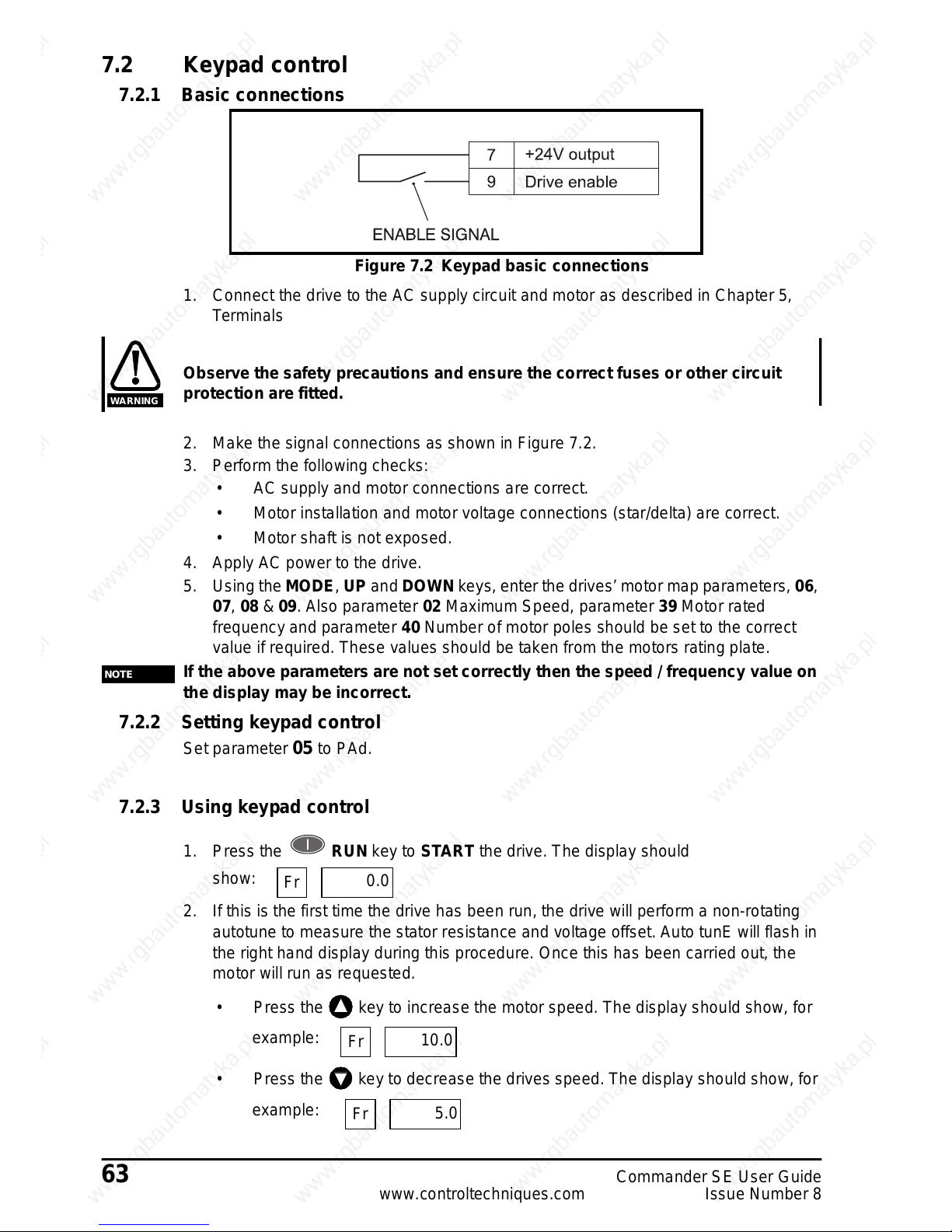
63 Commander SE User Guide
www.controltechniques.com Issue Number 8
7.2 Keypad control
7.2.1 Basic connections
Figure 7.2 Keypad basic connections
1. Connect the drive to the AC supply circuit and motor as described in Chapter 5,
Terminals
Observe the safety precautions and ensure the correct fuses or other circuit
protection are fitted.
2. Make the signal connections as shown in Figure 7.2.
3. Perform the followingchecks:
• AC supply and motor connections are correct.
• Motor installation and motor voltage connections (star/delta) are correct.
• Motor shaft is not exposed.
4. Apply AC power t o the drive.
5. Usingthe MODE, UP and DOWN keys, enter the drives’ motor map parameters, 06,
07, 08 & 09. Also parameter 02 Maximum Speed, parameter 39 Motor rated
frequency and parameter 40 Number of motor polesshould be set to the correct
value if required. These values should be taken from the motors rating plate.
If the above parameters are not set correctly then the speed / frequency value on
the display may be incorrect.
7.2.2 Setting keypad control
Set parameter 05 to PAd.
7.2.3 Using keypad control
1. Press the RUN key to START the drive. The display should
show:
2. If this is the first time the drive has been run, the drive will perform a non-rotating
autotune to measure the stator resistance and voltage offset. Auto tunE will flash in
the right hand display during this procedure. Once this has been carried out, the
motor will run as requested.
• Press the key to increase the motor speed. The display should show, for
example:
• Press the keyto decrease the drives speed. The display should show,for
example:
WARNING
NOTE
Fr
0.0
Fr
10.0
Fr
5.0
Page 71

CommanderSE User Guide 64
Issue Number 8 www.controltechniques.com
•Pressthe STOP key to STOP the drive. The display should show:
3. If the drive tripsduring thesetests the display will show,for example
The right hand display will flash with the trip code
4. Press the RESET buttontoresetthetrip.Pressthe RUN button to run
the drive.
5. The FORWARD/REVERSE button can be enabled by setting parameter 26 =
On.
If this test has been carriedoutas a benchtestand the drive is to be connected to
a different motor with differe nt characteristics etc. in the application, then the
motor map parameters should be set to the correct values for the new motor and
another autotun e carried out (see parameter 38 for details).
rd
0.0
tr
OU
NOTE
Page 72

65 Commander SE User Guide
www.controltechniques.com Issue Number 8
8 Diagnostics and Protective Features
Do not attempt to carry out internal repairs. Return a faulty drive to the supplier
for repair.
The following protective features are incorporated withinthe Commander SE drive.
They are placed in order of Tripnumber whichis the figure that is read back throughthe
serial comms.
8.1 Trip codes
When a trip conditionoccurs, the left hand display will show the legend whilst t he
righthand display flashes one of the tripcodes givenin Table 8.1.
WARNING
tr
Trip Code Trip
Number
Condition Possible Cause
UU
1 DC link under voltage
Low AC supply voltage
Low DC link voltage when supplied by external
DC power supply
OU
2 DC link over voltage
Excessive inertia in the machine during
deceleration
Deceleration rate set too fast for inertia of
machine
OI.AC**
3 AC instantaneous over current trip
Insufficient ramp times
Phase to phaseor phase to earth short-circuit at
the drive output
Drive requires autotuning to motor
Motor or motor connections changed, re-
autotune drive to motor (see parameter 38)
OI.br**
4 Overcurrent on braking IGBT
Excessive current in braking resistor
Braking resistor value too small
(Does not apply to Size 1 units)
Et
6 External trip
External trip terminal opened (when
programmed)
O.SP
7 Over speed
Excessive motor speed (typically caused by the
mechanical load driving the motor)
tunE 18 Auto-tune failure Motor loaded or no motor connected
It.br
19 Ixt on braking resistor
Excessive braking resistor energy
(Does not apply to Size 1 units)
It.AC
20 Motor overload on current x time
Too much mechanical load
High impedance phase to phase or phase to
earth short circuit at driveoutput
Drive requires autotuning to motor
Motor or motor connections changed, re-
autotune drive to motor (see parameter 38)
Oht1 21 Overheat Overheat thermal model
Oht2† 22 Overheat (heatsink thermistor) Temperature exceeds 95°C (203°F)
th 24 Over temperature (Motor thermistor) Excessive motor temperature
O.Ld1* 26 +24V or digital output overload Excessive load or short circuit on +24V output
cL
28 Current loop loss on terminal 5
Input current less than 3mA when 4-20 or 20-4
modes used
SCL
30
User serial communications
watchdog failure
Failure of serial communications between drive
andmaster
Page 73

CommanderSE User Guide 66
Issue Number 8 www.controltechniques.com
Table 8.1 Trip Codes
* The Enable/Reset terminal will not reset an O.Ld1 trip. Use the Stop/Reset key.
** These trips cannot be reset for 10 seconds.
† CommanderSE Size 4 temperature exceeds 100°C (212°F)
††
See information under terminal 5 on page 37.
If any of the above trips persist, please consult a Drive Centre.
OU - Overvoltage trip levels:
200V units - 420Vdc
400V units - 830Vdc
Braking levels:
200V units - 390Vdc
400V units - 780Vdc
UU - Undervoltage trip levels:
200V units - 180Vdc
400V units - 400Vdc
Reset from UU - Under voltage trip:
200V units - 235Vdc
400V units - 460Vdc
These are the absolute minimum DC voltages that the drive can be suppliedby.
EEF
31 Failure of internal EEPROM
Possible loss of parameter values
Corruption due to severe electrical noise
Set default parameters (see parameter 29)
PH
32 Phase loss
One of the input phases has become
disconnected from the drive. (This applies to
200V/400V three phase units only, not dual
rated units).
rS
33
Stator resistance measurement
failure
Motor cable disconnected during measurement
Motor too small for drive
See parameter 38 for more details
trxx
40-99
User trips where xx is the user trip
number
F.bus 180 Field bus disconnection whilst in use
C.Err 182 Quickey memory corrupt Bad connection or memory corrupt
C.dat
183 Quickey with no data
New / empty Quickey being read
Quickey / drive software compatibility issue
C.Acc 185 Quickey write fail Bad connection or faulty Quickey
C.rtg
186 Quickey voltage rating change
Already programmed Quickey read by drive of
different rating
O.Ld2
188
+28V serial communications power
supply overload
Overload of more than 1 10 mA or short circuit
on +28V serial communications power supply
O.cL†† 189 Current loop input overload Input current exceeded 25mA
Motor runs unstable
Motor or motor connections changed. Check
motor connections and
re-autotune drive to motor (see parameter 38)
Trip Code Trip
Number
Condition Possible Cause
NOTE
Page 74

67 Commander SE User Guide
www.controltechniques.com Issue Number 8
8.2 Alarm warnings
There are three ALARM codes which flashin the right hand display, along with the
standard display, to warn the user that if no action is taken, the drive will trip. The codes
are shown in Table 8.2.
For example:
Table 8.2 Alarm Warnings
* Does not apply to Size 1 units.
8.3 HF-Hardware fault trip codes
HF trips are internal hardware faults within the drive. Powering the drive down and re-
applying power could clear the fault.
For full list of hardware fault trip codes, refer to the Commander SE Advanced User
Guide.
If a HF trip occurs, the Drive Healthyrelay will open to indicate this. The serial
communications willnot function during a HF trip.
Display Condition Cause Solution
OVL
lxtoverload
Motor current greater than
programmed rated motor
current
Reduce motor current (load)
hot
Heatsink/IGBT
junctiontemperature
high
Drive running outside
specified ambient
temperature/motor current
rating curves
Reduce ambient
temperature or reduce
motor current (load)
*br.rS
Braking resistor
overload
Braking resistor thermal
model exceeded
See Commander SE
Advanced User Guide
Fr
50.0
hot
50.0
NOTE
Page 75
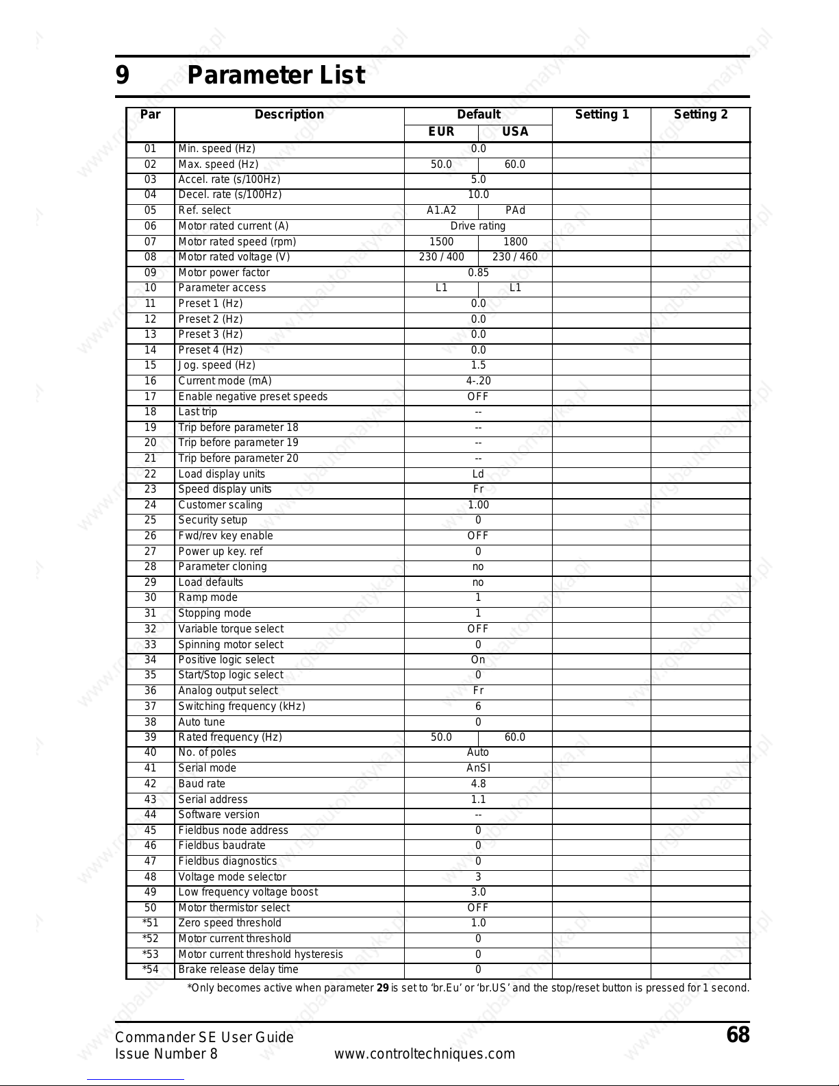
CommanderSE User Guide 68
Issue Number 8 www.controltechniques.com
9 Parameter List
*Only becomes active when parameter 29 is set to ‘br.Eu’ or ‘br.US’ and the stop/reset buttonis pressed for 1 second.
Par Description Default Setting 1 Setting 2
EUR USA
01 Min. speed (Hz) 0.0
02 Max. speed (Hz) 50.0 60.0
03 Accel. rate (s/100Hz) 5.0
04 Decel. rate (s/100Hz) 10.0
05 Ref. select A1.A2 PAd
06 Motor rated current (A) Drive rating
07 Motor rated speed (rpm) 1500 1800
08 Motor rated voltage (V) 230 / 400 230 / 460
09 Motor power factor 0.85
10 Parameter access L1 L1
11 Preset 1 (Hz) 0.0
12 Preset2 (Hz) 0.0
13 Preset3 (Hz) 0.0
14 Preset4 (Hz) 0.0
15 Jog. speed (Hz) 1.5
16 Currentmode (mA) 4-.20
17 Enable negative preset speeds OFF
18 Last trip --
19 Trip before parameter18 --
20 Trip before parameter19 --
21 Trip before parameter20 --
22 Loaddisplay units Ld
23 Speed display units Fr
24 Customerscaling 1.00
25 Securitysetup 0
26 Fwd/rev key enable OFF
27 Power up key.ref 0
28 Parameter cloning no
29 Loaddefaults no
30 Rampmode 1
31 Stopping mode 1
32 Variable torque select OFF
33 Spinning motor select 0
34 Positive logic select On
35 Start/Stop logic select 0
36 Analog output select Fr
37 Switching frequency(kHz) 6
38 Autotune 0
39 Ratedfrequency (Hz) 50.0 60.0
40 No. of poles Auto
41 Serial mode AnSI
42 Baudrate 4.8
43 Serial address 1.1
44 Software version --
45 Fieldbusnode address 0
46 Fieldbusbaudrate 0
47 Fieldbusdiagnostics 0
48 Voltage mode selector 3
49 Low frequency voltage boost 3.0
50 Motor thermistor select OFF
*51 Zero speed threshold 1.0
*52 Motor current threshold 0
*53 Motor current threshold hysteresis 0
*54 Brake release delay time 0
Page 76

69 Commander SE User Guide
www.controltechniques.com Issue Number 8
10 Advanced Functions
TheCommanderSE can also offermany advancedfunctions. A full explanationofthese
canbefoundintheCommander SE Advanced UserGuide.
10.1 Speed control
• Adjustable precision speed reference
• 3 adjustable skip frequencies with 3 adjustable skip bands
• 8 adjustable preset speeds
10.2 Ramps
• 8 preset acceleration ramps
• 8 preset deceleration ramps
• Separate acceleration and deceleration ramps for preset speeds
• Separate acceleration and deceleration ramps for jogging
• Adjustable S-ramp
10.3 Torque control
10.4 Stopping
• Adjustable DC injection braking current level and time
10.5 Programmable I/O
• Fully programmable analog and digital I/O for alternative functions
10.6 Motor protection
• Current limiting (short-term overload)
• Motor thermistor protection (long-term overload)
• Protection trips with trip log
10.7 Monitoring
• Programmable drivestatus logic
• Status and diagnostic information
•kWhmeter
•Runtimelog
• Adjustable speed sensing levels
• Running costs
10.8 Auxiliary functions
• Auto reset
• PID controller
• Un-dedicated programmable logic
• Un-dedicated programmable threshold comparator
• Motorised potentiometer
10.9 Second motor selection
• With second motor map parameters
Page 77

CommanderSE User Guide 70
Issue Number 8 www.controltechniques.com
11 UL Listing Information
11.1 Common UL information
Conformity
The driveconforms to UL listing requirements only when the followingare observed:
• Class 1 60/75°C (140/167°F) copper wire only is used in the installation.
• The ambient temperature does not exceed 40°C(104°F) when the drive is
operating.
• The terminal tightening torques specified in Chapter 5 Terminals are used.
• Thedriveis installed intoa separate electricalenclosure. The drive has a UL ‘Open-
type’ enclosure rating.
AC Supply Specification
The drive is suitable for use in a circuit capable of delivering not more than 5000RMS
symmetrical Amperes at 264VacRMS maximum (200Vmodels) or 528Vac RMS
maximum (400V models).
Motor Overload Protection
The driveprovides motor overload protection. The overload protection level is 150% of
full-load current. It is necessary for the motor rated currentto be entered intoparameter
6 for the protect ion to operate correctly. The protection level may be adjusted below
150% if required.Refer to the CommanderSE AdvancedUser Guide for further
information.
Overspeed Protection
The drivedoes not incorporate overspeed protection.
11.2 Power dependant UL information
11.2.1 Commander SE Size 1
Conformity
The drive conforms to UL listing requirements only when the following is observed:
• UL listed class CC fast acting fuses e.g. Bussman Limitron KTK series, Gould Amp-
Trap ATM series or equivalent are used in the AC supply.
11.2.2 Commander SE Size 2
Conformity
The driveconforms to UL listing requirements only when the followingare observed:
• UL listed class CC fast acting fuses e.g. Bussman Limitron KTK series, Gould Amp-
Trap ATM series or equivalent are used in the AC supply for 200 and 400Vac input
models with the following exceptions:
• The SE2D200220when operated from a single phase supply must use a 35A UL
listedclass J fast acting fuse e.g. Gould Amp-Trap A4J35 or Litte lfuse Power-Gard
JLS35.
• With reference to Table 3.7, the SE23200400 may use 30A UL listed class CC fast
actingfuses.
• The power input wiring for the following models should be terminated with UL listed
(to UL486A/C) 12 AWG ring terminals (max. allowable diameter 8.0mm):
SE2D200220 when used on a single-phase supply
SE23200400
11.2.3 Commander SE Size 3, 200V product
Conformity
The drive conforms to UL listing requirements only when the following is observed:
Page 78

71 Commander SE User Guide
www.controltechniques.com Issue Number 8
• UL listed class J 35A fast acting fuses e.g. Gould Amp-Trap A4J35, Littelfuse Power
Gard JLS35 or equivalent are used in the AC supply.
11.2.4 Commander SE Size 3, 400V product
Conformity
The driveconforms to UL listing requirements only when the following is observed:
• UL listed class CC fast acting fuses e.g. Bussman Limitron KTK series, Gould Amp-
Trap ATM series or equivalent are used in the AC supply.
11.2.5 Commander SE Size 4
Conformity
The driveconforms to UL listing requirements only when the following is observed:
• UL listed class J 40A fast acting fuses e.g. Gould Amp-Trap A4J40, Littelfuse
Power-Gard JLS40 or equivalent are used in the AC supply.
11.2.6 Commander SE Size 5
Conformity
The driveconforms to UL listing requirements only when the following is observed:
• The drive is installed in a Type 1 enclosure, or better, as defined by UL50
• ULlistedclassRK1600VacfusesareusedintheACsupply
11.2.7 Commander SE RFI Filters
All recommended filters for CommanderSE are UL recognised components, including
for Canada (CUL), under file number E64388.
 Loading...