

Page 1
Quantum III
CTi Automation - Phone: 800.894.0412 - Fax: 208.368.0415 - Web: www.ctiautomation.net - Email: info@ctiautomation.net
Compact DC Drive Package
The Quantum III delivers a DC drive package that
integrates the intelligence of the Mentor II with a
space saving design that incorporates many accessories
typically required in the North American market.
Quantum III drives are ready to install and run DC
motors. Like the Mentor II, they are easily configurable
to control motor speed, voltage or current using
standard internal settings. Set-up is convenient using
the drive keypad, or MentorSoft, a Windows based
drive configuration tool. These drives have powerful
diagnostic and communication abilities.
The simple addition of the MD29 applications card
enables users to incorporate custom or proprietary
process control application programs to their drive.
The Quantum III also provides extensive communication
protocol options.
Quantum III
The powerful microprocessor based Mentor is the
central component of the Quantum package. The
integrated design includes fuses, a DC loop contactor,
and 115 VAC interface logic control, making it an
ideal choice for end users with space constraints. The
Quantum III offers a compact DC package solution.
You’ll also find the Quantum III on OEM equipment and
integrated systems.
www.emersonct.com
800-893-2321
—Slitter
—DC Drive Package
284
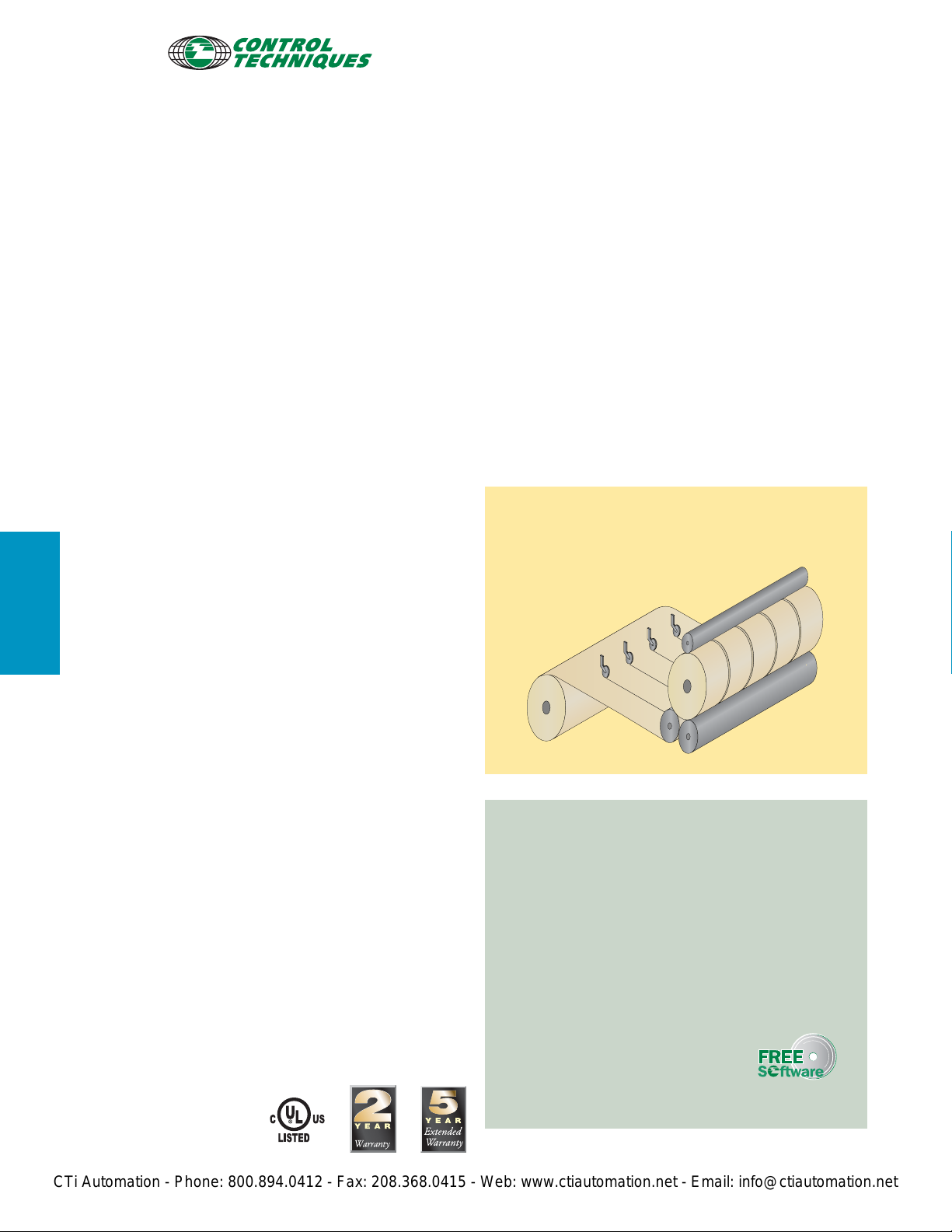
DC drive technology has proven to be extremely
reliable and is ideally suited to web handling, winders,
slitters, extruders, wire drawing, converting lines, and
plastics production. The Quantum III meets the many
requirements of these industries.
In addition to the features of the Mentor II, the
Quantum III drive includes:
•
High speed semiconductor fusing
•
115 VAC control interface
•
DC loop contactor
(with DB pole up to 250 hp @ 480 VAC)
•
Accepts AC/DC tachometer feedback, and
AC/DC pulse feedback
•
DC output fuse on all regen models
Digital Drive
• Microprocessor Based Digital DC Drive
• 5 to 1000 hp, 3 phase,
208 / 230 / 380 / 480 VAC
• Regenerative and non-regenerative models
• RS485 serial communications
• Extensive fieldbus communication
capabilities
• Plug-in 32-bit application coprocessor
card (MD29)
• MentorSoft, Windows based
drive configuration tool
•
Complete Motor Solutions
Note: UL only available through 400 hp @ 460V and 200 hp @ 230V
Page 2
www.emersonct.com
CTi Automation - Phone: 800.894.0412 - Fax: 208.368.0415 - Web: www.ctiautomation.net - Email: info@ctiautomation.net
800-893-2321
FEATURE/PERFORMANCE ADVANTAGE
High-speed semiconductor fusing
Provides short circuit protection for SCRs
DC loop contactor (with DB pole up to 250 hp @ 480 VAC)
Enables easy addition of dynamic braking resistors
115 VAC control interface
Allows use with standard remote operator devices
Profibus-DP, Modbus+, Modbus RTU, Interbus-S, DeviceNet,
and CTNet plug-in communication cards
Communicates on user’s preferred network
Programmable threshold comparators
Expands application possibilities by providing a pair
of independent numerical comparators with
adjustable hysteresis
Extensive and configurable analog and digital I/O
Customizes drive to specific applications
Programmable boolean logic (AND, NAND, OR, NOR) gates
with delay outputs
Assists with general system interface logic needs,
expanding application possibilities
Built-in digital lock function for frequency following
Allows accurate master / follower applications
Accommodates AC/DC tachometer and encoder feedback
Enables precise speed control
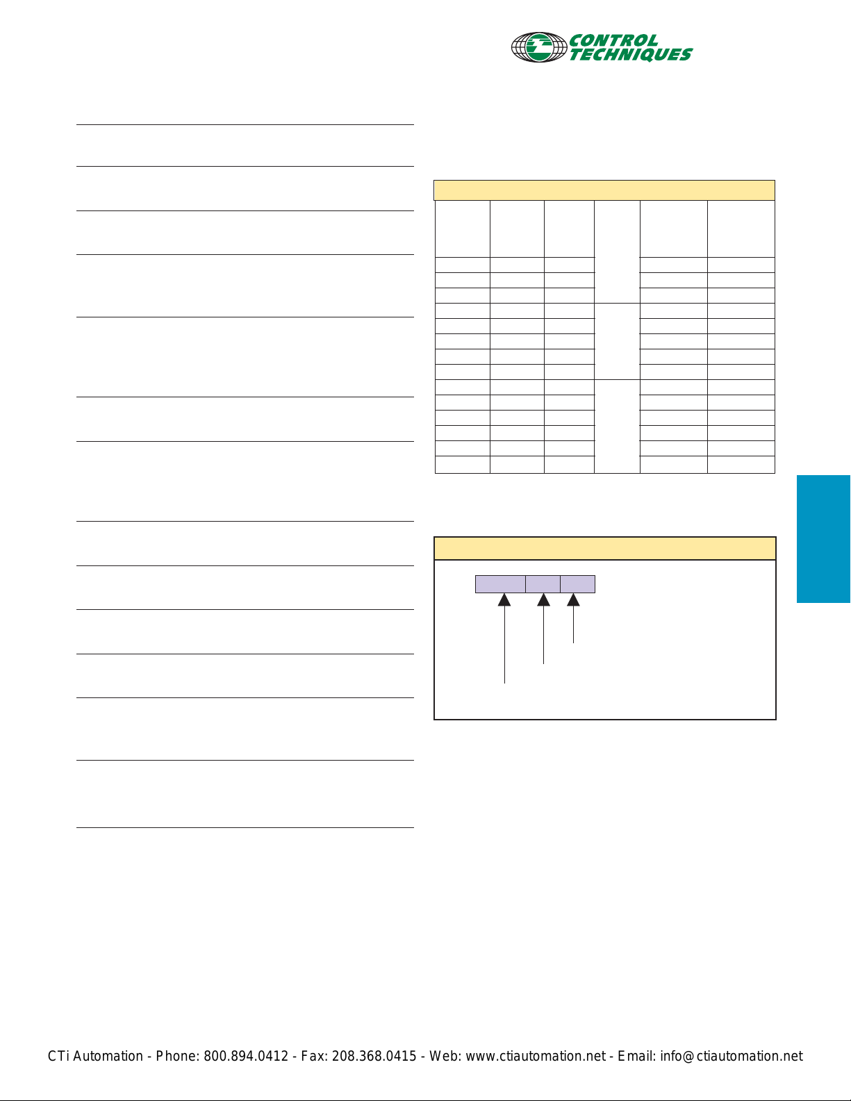
RATINGS: QUANTUM III
THREE PHASE INPUT DC Arm Output Field Output
3 to 500 hp (208-230 VAC) (240VDC) (150VDC)
5 to 1000 hp (380-460 VAC) (500VDC) (300VDC)
240 / 480 VAC
Motor HP
240 VAC
3 to 10 5 to 20 38 9500-8302 9500-8602
15 25 to 30 55 9500-8303 9500-8603
20 to 30 40 to 60 106 9500-8305 9500-8605
40 to 50 75 to 100 172 9500-8306 9500-8606
75 150 255 9500-8307 9500-8607
100 200 338 9500-8308 9500-8608
125 250 428 9500-8309 9500-8609
150 300 508 9500-8310 9500-8610
200 400 675 9500-8311 9500-8611
250 500 820 9500-8315 9500-8615
300 600 985 9500-8316 9500-8616
- 700 1150 9500-8317 9500-8617
400 800 1250 9500-8318 9500-8618
- 900 1470 9500-8319 9500-8619
500 1000 1620 9500-8320 9500-8620
➀ Drive includes DC loop contactor, input fuses and 120 VAC interface.
➁ For field control, add external field regulator P/N 9500-9035.
➂ Ambient temperature is 55˚C.
Motor HP
480 VAC
Output
Current➂
(A)
Output
Current
Current
Regulated
Voltage
Voltage
Order String
9500 xx x
Field
8A
10A
Fixed
➁
20A
Fixed
➁
Non-Regen
Order
Code➀
Regen
Order
Code➀
Quantum III
Extensive diagnostics and fault indicators
Used for accurate drive system diagnosis
Accepts wide range of supply voltage (208 to 480 VAC)
Can be applied to worldwide voltages
Non-regen and regen models share the same footprint
Provides for common mechanical design and
mounting
Special Field supply
Three Phase Input Field Output
(208-230VAC) (240VDC)
Model Number: 02 through 20
Non-regen = 83, Regen = 86
Quantum III Product Family
285
Page 3

TERMINAL DIAGRAM: QUANTUM III
CTi Automation - Phone: 800.894.0412 - Fax: 208.368.0415 - Web: www.ctiautomation.net - Email: info@ctiautomation.net
www.emersonct.com
800-893-2321
Quantum III
286
Page 4

www.emersonct.com
CTi Automation - Phone: 800.894.0412 - Fax: 208.368.0415 - Web: www.ctiautomation.net - Email: info@ctiautomation.net
800-893-2321
LOGIC INTERFACE BOARD (9500-4030)
TBS
Pin# Function Type/Description Notes
1, 3 Shunt Resistor Connection Horsepower Used up through
Programming 9500-8306 / 8606
2 No Internal Connection
4, 5 Optional Motor Thermostat Contact Input Provides thermal trip
6 +24 VDC Supply User Supply 100 mA max
TBA
Pin# Function Type/Description Notes
1 DC Tachometer Input (-) Analog Input 300 VDC max
3 DC Tachometer Input (+)
1, 2 AC Tachometer Input Analog Input 200 VAC max
Mentor II Control board (MDA2B)
Pin# Function Type/Description Notes
1 +10 VDC Reference Supply 10 mA max
2 -10 VDC Reference Supply 10 mA max
3 Speed Reference Analog Input, 12 bit
4 Analog Input # 1
5 # 2 Analog Input
6 # 3 Bi-polar, 10 bit + sign
7 # 4
8, 9,
10
11 Armature Current Image Analog Output 6.6 VDC @ 150%
current
12 Analog Output # 1 Analog Output
13 # 2 Bi-polar, 10 bit + sign ±10 VDC, 5 mA
14 # 3
15 Digital Output # 1
16 # 2 Digital Output +24 VDC, 100 mA
17 # 3 Open Collector
18 # 4
19 For Internal Use
20 0V Common Circuit Common
21
to 26
27 Digital Input F7
28 F8 Digital Input +24 VDC, 10k Ohms
29 F9
30 F10
31 For Internal Use
34 Form C Status Relay Relay Common
35 (Zero Speed) N.C. Contact 110 VAC, 5A resistive
36 N.O. Contact
37,
38, For Internal Use
39
40 0V Common Circuit Common
Programmable Analog Programmable Digital All Analog I/O is scalable
For Internal Use
For Internal Use
±10 VDC, 100k Ohms
or 4 - 20 mA, 100 Ohms
±10 VDC, 100k Ohms
Terminal Descriptions: Quantum III
120 VAC Interface Board (9500-4025)
Pin# Function Type/Description Notes
1 120 VAC high side (fused) Power Supply 120 VAC
2, 3 Tie Point No Internal Connection Customer Use
4 External Trip / Motor 120 VAC Input
Thermostat Input (Fault relay coil)
5 120 VAC (when drive OK) 120 VAC Output
6 Stop / Seal-in Input Contact Input For 3-wire Stop / Start
control
7 Run Input Input (Run relay coil) 120 VAC
8, 9 Jog Input Input (Jog relay coil) 120 VAC
10 120 VAC high side (fused) Power Supply 120 VAC
11 Input # 1 (Reverse) Programmable Input 120 VAC
(# 1 relay coil)
12 Input # 2 (Drive Reset) Programmable Input 120 VAC
(# 2 relay coil)
13, 14 Run / Jog Contact N.O. Output Contact 120 VAC
15, 16 No Fault Contact N.O. or N.C. Contact 120 VAC
17, 18 Fault Relay Contact (selectable)
19 Programmable Form C Common Connection
(arm)
20 N.C. Connection 120 VAC
21 Relay Contact # 1 N.O. Connection
22, 23 Programmable Relay N.O. or N.C. Contact 120 VAC
Contact # 2 (selectable)
24 Drive ON Output 120 VAC, 6 VA max
25 120 VAC low side 120 VAC Common Earth ground
Connection
Quantum III
When you need it FAST!
See the RapidPak pages in the Packaged Drives
and Engineered Systems section for details.
287
Page 5

www.emersonct.com
CTi Automation - Phone: 800.894.0412 - Fax: 208.368.0415 - Web: www.ctiautomation.net - Email: info@ctiautomation.net
800-893-2321
SPECIFICATIONS: QUANTUM III
Environment
Ambient Operating 0 to 55°C (32 to 131°F)
Temperature
Cooling Method Convection and forced convection,
model dependent
Humidity 95% non-condensing at 55°C (131°F)
Storage Temperature -40 to 55°C (-40 to 131°F)
Altitude 0 to 4000m (13,120 ft). Derate 1% per 100m
(328 ft) between 1000m (3,280 ft) and
4000m (13,120 ft).
Enclosure Chassis (IP00)
Voltage 208 to 480 VAC -5%, +10%
Phase 3Ø
Frequency 45 to 62 Hz
Efficiency 98%
Standard Field Size 1 – 0.9 X input VAC (Regulated),
Output Voltage Size 2-3 – .67 X input VAC (Non-Regulated)
Non-Standard Field – Consult Factory
Armature Output Non-Regen – 1.15 X input VAC,
Voltage Regen – 1.05 X input VAC
Quantum III
Feedback Methods Armature Voltage (resolution .83 volts)
DC Tachometer (resolution 0.1%)
Encoder (resolution .01%)
Field Control Current regulated (9500-8306 / 8606
and smaller)
Voltage Regulated (9500-8307 / 8607 and larger)
Analog Input Resolution 12 bit (Qty 1), 10 bit (Qty 4)
Serial Communications 4-wire RS422 or RS485, optically-isolated
Protocol is ANSI x 3.28-2.5-A4
Baud rate is 4800 or 9600
Protection
AC Line 180 VAC
Undervoltage Trip
MOV Voltage Input transient suppression
Transient Protection
Instantaneous 300% armature current
Overcurrent Trip
Armature Open Circuit Armature circuit is open
Drive Overload Trip Inverse time, 150% for 30 seconds
Phase Loss Trip Loss of input phase
Overtemperature Trip Heatsink exceeds 100°C (212°F)
Motor Thermal Trip Motor over-temp switch or Thermistor
Feedback Loss Loss of motor feedback
Feedback Reversal Tachometer or Encoder wired backwards
Field Loss No field current
Field On Field current during auto-tune
Field Overcurrent Field current greater than field demand
Current Loop Loss Loss of 4-20 mA reference
External Power Supply Short circuit on +24 VDC user power supply
Power Supply Internal power supply out of tolerance
Serial Mode 3 serial comms data loss
AC Supply Requirements
Control
Protection continued
Communications Loss
Processor 1 Main control processor fault
Watchdog Trip
Processor 2 Second control processor fault (MD29)
Watchdog Trip
Hardware Fault Hardware malfunction on control board
Memory Fault Stored parameter checksum fault
External Trip User interlock fault (programmed)
Software Fault (A29) MD29 software fault
Approvals & Listings
UL, cUL File #E58592 Vol. 1 Section 19
(Partial - check with factory for details)
CE Designed for marking
ISO 9002 Certified Manufacturing Facility
Dimensions
MODE
▲
▲
PARAMETER DATA
▲
PARAMETER INDEX
Drive Ready
Alarm
Zero speed
Run forward
Run reverse
Bridge 1
Bridge 2
At speed
Current limit
RESET
H x W x D
Approx.
Weight (lbs.)
▲
Size Order Code Size* (in)
9500-8302 thru 9500-8303 15 x 10 x10.5 44
9500-8602 thru 9500-8603 15 x 10 x10.5 44
1
9500-8305 thru 9500-8306 15 x 10 x 12.3 53
9500-8605 thru 9500-8606 15 x 10 x 12.3 53
9500-8307 thru 9500-8309 35 x 20.3 x 12 110
9500-8607 thru 9500-8609 35 x 20.3 x 12 110
2
9500-8310 thru 9500-8311 36 x 20.3 x 14 155
9500-8610 thru 9500-8611 36 x 20.3 x 14 155
9500-8315 thru 9500-8318 54 x 34 x 19 397
9500-8615 thru 9500-8618 72 x 34 x 19 475
3
9500-8319 thru 9500-8320 54 x 34 x 19 443
9500-8619 thru 9500-8620 72 x 34 x 19 525
* Approximate, not to be used for construction purposes.
288
 Loading...