

Page 1

User Guide
Profibus-DP
Option Module
For Uni dri ve
Part Number: 0460-0075
Issue Number: 3
Page 2
SAFETY INFORMATION
Persons supervising an d performing the electric al installation or maintenanc e of a
Drive and/or an exter nal Option Unit mus t be suitably qualified and c ompetent in
these d uties. T hey should be given t he opport unity to s tudy and i f necess ary to
discuss this User Guide before work is started.
The volt ages pr es ent in the Dr ive an d ext ern al Opt ion U nits are cap able of i nflic ting
a severe electric shock and may be lethal. The Stop function of the Drive does not
remove dangerous voltages from the terminals of the Drive and exter nal Option
Unit. Mains supplies should be removed before a n y se r vicing work is performed.
The inst allation ins tructi ons should b e adhered t o. Any questi ons or doubt s hould
be referred to the supplier of the equipment. It is the responsibility of the owner or
user to ens ure that th e installation of the Drive and external O ption Unit, and the
way in whic h they are op erated and maintain ed complies with the req uirements of
the Healt h an d Saf ety at W ork Act i n the U nit ed Ki ngd om and applicable l egis lati on
and regul ati ons an d c od es of pr act ice in the UK or elsewh ere.
The Drive software may incorporate an optional Auto-start facility. In order to
prevent the risk of injury to personnel working on or near th e motor or its driven
equipm ent and to prevent pot ential dam age to equipm ent, users and oper ators, all
necess ar y precauti ons m us t be tak en if operating t h e Dr i ve in th is m o d e.
The Stop and Start inputs of t he Drive should n ot b e r elied upon to ensure safety of
personn el. If a safety haz ard coul d exist from une xpect ed st arting of th e Drive, an
interlock should be in stalled to pre vent the motor be ing inadverte ntly started.
GENERAL INFORMATION
The manufacturer accepts no liability for any consequences resulting from
inappropriate, negligent or incorrect installation or adjustment of the optional
operating parameters of the equipment or from mismatching the Drive with the
motor.
The contents of this User Guide are believed to be correct at the time of printing. In
the interests of a commitment to a policy of continuous development and
improv em en t, the m an ufacturer res erves th e right to chan g e the sp ec if ic ation of th e
product or its performance, or the contents of the User Guide, without notice.
All rights reserved. No part of this User Guide may be reproduced or transmitted in
any form or by any means, electrical or mechanical including photocopying,
recordin g or by any inform ation storage or retri eval syst em, without permissi on in
writing f r om th e pu blisher.
Copyright © January 2001 Control Techniques SSPD
Author Paul Bennett
Issue Code Issue 3
System File V2.07.03
Hardware (UD73) Issue 1
Firmware (UD73) V2.04.00
Page 3

Contents
1 Introduction 4
1.1 Profibus-DP Interface for Unidrive 4
1.2 Product Conformance Certification 4
1.3 Overview Specification 4
2 Mechanical Installation 4
2.1 Unidrive 4
3 Electrical Installation 4
3.1 Profibus-DP Connectors 4
3.2 Profibus-DP Data Conne ct ions 4
3.2.1 ERNI Connector 4
3.2.2 Siemens Connector 4
3.3 Profibus-DP Cable 4
3.4 Profibus-DP Cable Scre en Connections 4
3.5 Profibus-DP Network Termination 4
3.5.1 ERNI Termination Connector 4
3.5.2 Siemens Connector 4
3.6 Maximum Network Length 4
4 Getting Started 4
4.1 Basic Communications Quick Start 4
4.2 Profibus-DP Node Address 4
4.3 Profibus-DP Data Rate 4
4.4 Data Format 4
4.5 Network Status 4
4.6 Network Loss Trip 4
4.7 Initialising Set-up Changes 4
5 Cyclic Data 4
5.1 What is Cyclic Data? 4
5.2 What is Data Consistency 4
5.3 Profibus-DP Data Formats 4
5.4 Mapping Parameters on Unidrive 4
5.5 Internal 32-Bit Parameters on UD70 4
5.6 Storing Parameters 4
5.6.1 Saving Unidrive Parameters (Menu 1 to 19) 4
5.6.2 Saving UD70 Parameters (Menu 20 and Internal) 4
5.7 Mapping Conflicts 4
5.7.1 Control Word Mapping Conflicts 4
5.8 Fieldbus Control Word for Unidrive 4
5.9 Fieldbus Status Word for Unidrive 4
5.10 Disabling Cyclic Data Channels 4
Page 4

6 Non Cyclic Data 4
6.1 CT Single Word Format 4
6.1.1 Reading p arameters us in g M ode 1 4
6.1.2 Writin g parame ters using Mode 1 4
6.2 Profibus-DP Set-up using Non-Cyclic Data 4
7 GSD Files 4
7.1 What are GSD Fil es? 4
7.2 Unidrive GSD File 4
7.3 Data Consistency 4
7.4 Profibus-DP Data Formats 4
8 Diagnostics 4
8.1 Fieldbus Code 4
8.2 Firmware Version 4
8.3 System File Version 4
8.4 Node Address 4
8.5 Network Data Rate 4
8.6 Network Status 4
8.7 No Da ta Transfer 4
8.8 Unidrive Trip Codes 4
9 Advanced Featu res 4
9.1 Network Loss Trip 4
9.2 Unidrive Sequencing Mode 3 4
9.3 Drive Reset Using The Profibus-DP Network 4
9.3.1 Reset Without DPL Code 4
9.3.2 Reset U sing CT Mode Non-Cycl ic Communications 4
9.3.3 Reset Using DPL Code 4
9.4 Non-Cyclic Parameter Store 4
9.5 Endian Format 4
9.6 EVENT Task Trigger on UD70 4
9.7 Multi-Master Networks 4
10 Quick R eference 4
10.1 Complete Parameter Reference 4
10.2 Profibus-DP Data Formats 4
10.3 Fieldbus Control Word 4
10.4 Fieldbus Status Word 4
10.5 Unidrive Trip Codes 4
Page 5

1 Introduction
NOTE
Unidrive paramet ers are denoted i n this ma nual by “ #MM .PP”, where
MM refers to the menu number, and PP refers to the parameter
number wi thi n that menu. Plea se ref er to t he Un idri ve Ad vanc ed User
Guide for a ful l list of parameter de f init ions.
1.1 Profibus-DP Interface for Unidrive
The Unidr ive Profibus-DP interface is s upplied as an option module,
with th e Prof ibus-DP usi ng a UD70 as th e host. The UD 70 does n ot
lose any functionality when the Profibus-DP interface is fitted. The
fastest data rate currently supported is 1.5 Mbits/sec.
The Unidr ive sup plies all p ower requ irem ents for th e Unidri ve Profi busDP interface. There is no provision for a back-up +24V power supply.
1.2 Product Conformance Certification
The Unidr ive Profibus-DP interf ace (wit h V2.05.00 fir mware, V2.08.00
system file and V5.0 GSD file) was submitted to the PROFIBUS
Nutzer organis ation f or c onfor mance t estin g. All tests wer e succ essf ul,
and the PROFIBUS Nutzerorganisation awarded full Profibus
Conformance Certification. (Profibus Certificate No. Z00600)
NOTE
Unidrive Profibus-DP interfaces fitted with V2.04.00 firmware or earlier
do NOT have Product Conformance Certification.
1.3 Overview Specification
• Auto slave configuration of data format and data consistency
during Profibus-DP network initialisation.
• Supported data rates (bits/sec): 1.5M, 500k, 187.5k, 93.75k, 19.2k,
9.6k
• Three 16 bit input/output words, all can be mapped to or from
Unidrive parameters
• CT Single Word Format non-cyclic data channel
Issue Number: 3 5
Page 6
2 Mechanical Installation
The Unidrive must be disconnected from the mains supply
before installing or removing an option module.
Warning
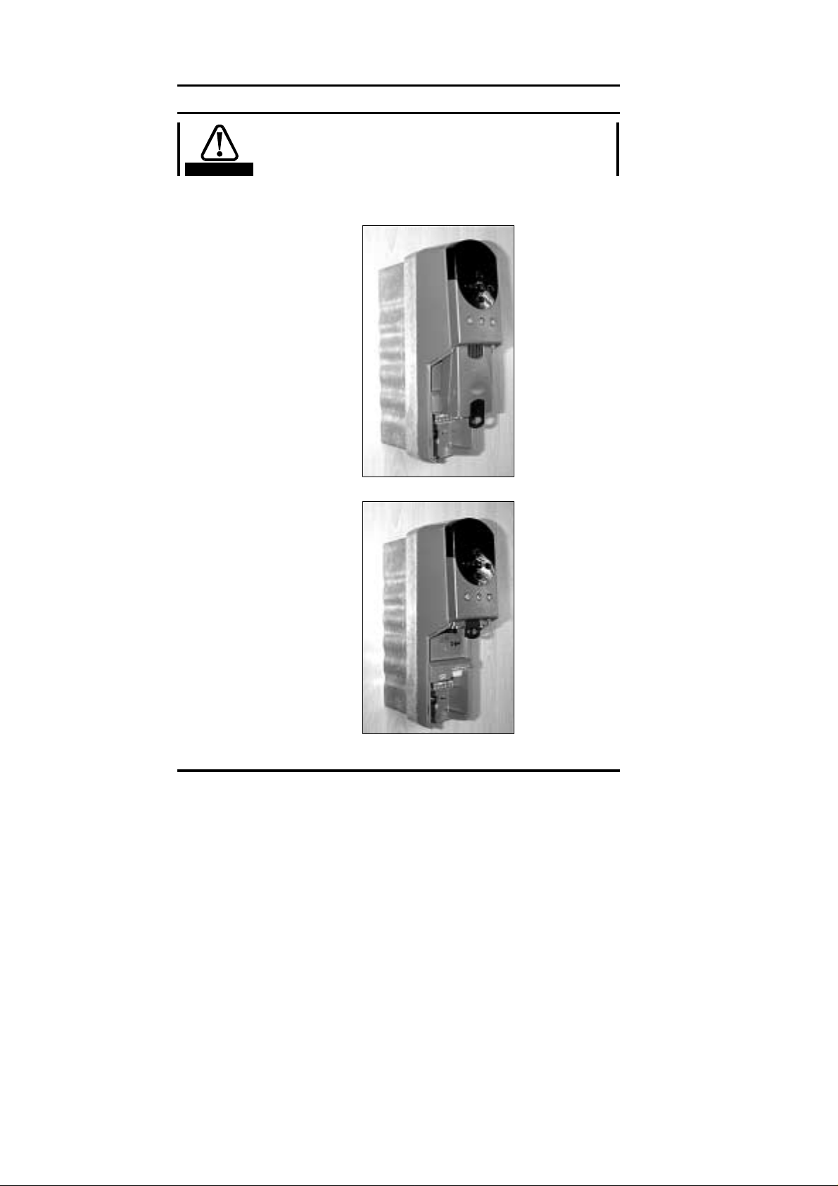
2.1 Unidrive
1. Slide the option modu l e int o th e Uni dr i ve.
2. Push the opt ion modul e int o th e Uni dr i ve u ntil it clicks into place.
6 Issue Number: 3
Page 7
3 Electrical Installation
3.1 Profibus-DP Connectors
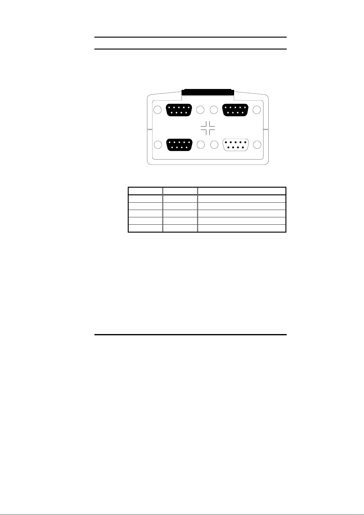
The Unidr ive Profib us-DP interf ace has two 9-way D-typ e sock ets (A
and B) to c onn ec t to t h e Profib us - DP network. Connectors C and D are
the RS232 programming port (C) and RS485 general-purpose
communications port ( D) of the UD 70.
AB
DC
The Profibus-DP connectors are parallel connectors, so either
connect or can be used. The pin - out conn ections are identic al, an d are
given in the table below.
Terminal Function Description
8 A Negative data Line
3 B Positive data Line
5 0V ISO 0V Isolated
6 VDC +5V line for termination resistors
Shell Screen Cable braided screen connection
3.2 Profibus-DP Data Connections
Specific ally desig ned connect ors are avail able for use on P rofibus-D P
networks that accept 2 Profibus-DP cables into colour-coded screw
termin als, and plug dir ectl y into a 9-way P rofibus -DP D-t ype con nect or.
A screen c lamp is also incl uded to ens ure good s creen c ontinuit y and
provide the best possible immunity to noise. Control Techniques
recomm ends that a sui table conn ector should be used to con nect the
Unidrive Profibus-DP interface to a Profibus-DP network.
Details of manuf actur ers of c onnect ors appr oved f or use wit h Profi busDP can be found on the Profibus web site at “www.profibus.com“.
Issue Number: 3 7
Page 8

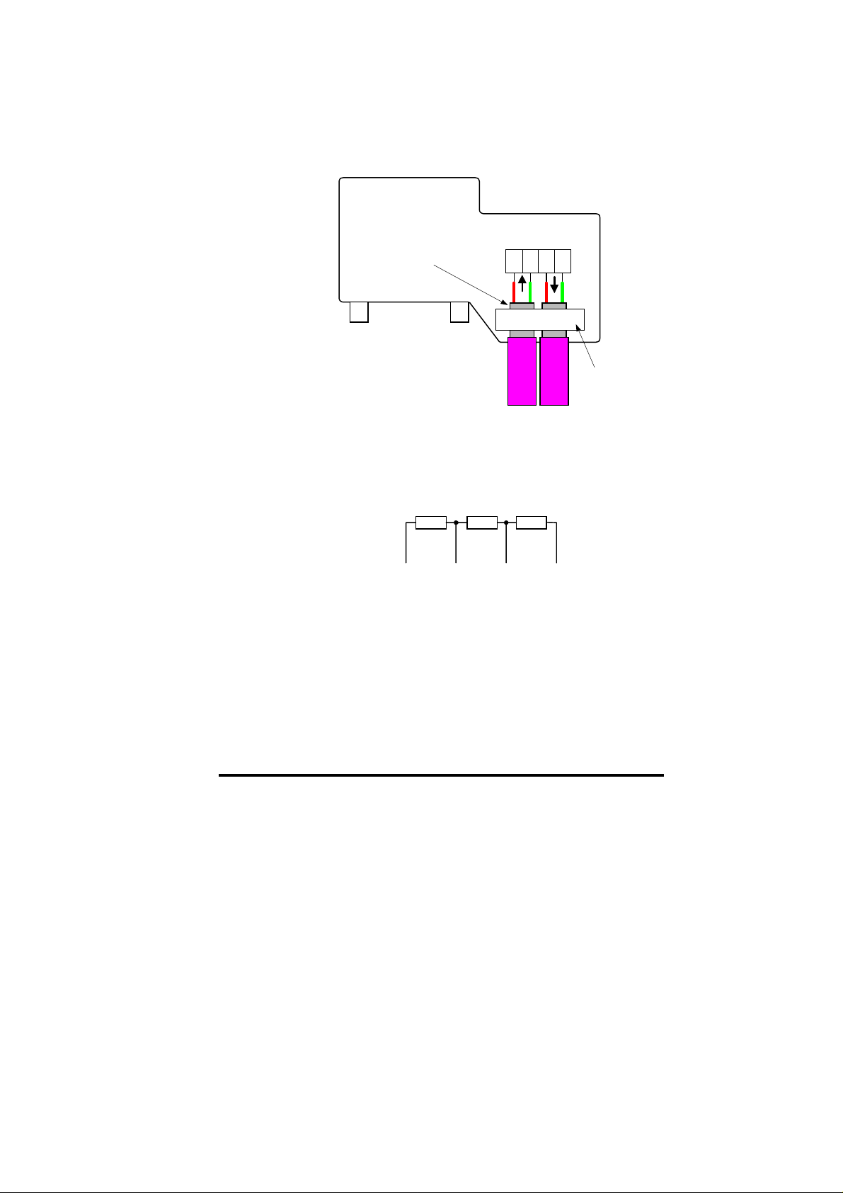
3.2.1 ERNI Connector
The ERbic range of fieldbus connectors from ERNI includes a
Profibus-DP connector with a vertical cable outlet (Part No. 103658)
that is suitabl e for us e with the Unidrive Profibus-DP interf ace. T his
connect or allows 2 c abl es t o be c onn ect ed t o th e s ame c onn ector , an d
does not br eak t he netw ork if disconn ected f rom th e Unidri ve Profi busDP interf ace. Further details are avai lable fr om the ERNI web sit e at
“www.erni.com”.
The ERNI c onnector can only be fitt ed to D-type c onnect or A on the
Unidrive Profibus-DP interface, as shown in the diagram below.
12345
6789
AB
DC
A
B
A
12345
6789
ABB
ERNI ER bi c P r of ib us
Connector with vertical
cabl e outlet
Part N o: 103658
Cable S c reen
Clamp
A termination connector is also available with the appropriate
termin ation r esis tors fitt ed ins id e the connec t or. Refer to secti on 3. 5 for
further details.
8 Issue Number: 3
Page 9
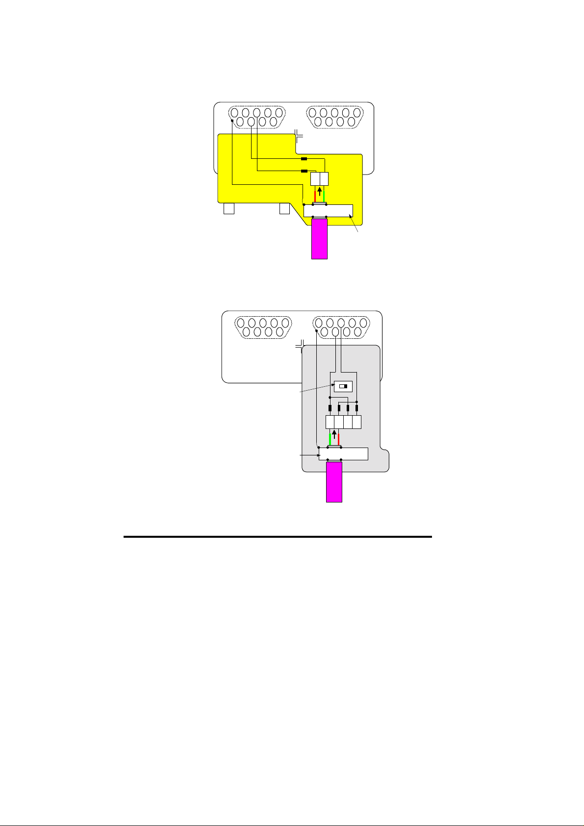
3.2.2 Siemens Connector
Another suitable Profibus-DP connector for use with Unidrive is
avail able from S iem ens. (P art No. 6G K1 50 0 0EA0 2.) This conn ector
has a s witc h th at c an enab le of dis abl e th e int ern al t ermi nati on r esis tor
network. When termination is enabled, the outgoing bus is isolated.
This connector allows 2 cables to be connected to the same connector,
and does not break the network if disconnected from the Unidrive
Profib us-DP int erfac e. Furth er details are avai lable f rom the Siemens
web site at “www.si em ens.de”.
The Siemens connector can be fitted to either Profibus-DP D-type
connector (A or B) on the Unidrive Profibus-DP interface.
12345
6789
Siemens RS485
Profibus Connector
Part N o: 6GK1 500 0EA02
Cable S c reen Cl am p
AB
DC
12345
6789
OFF
ON
A
B
B2A2B1A1
Issue Number: 3 9
Page 10

3.3 Profibus-DP Cable
Profib us-DP cable h as a sing le twist ed pair plus overall s c reening. The
data wires are usually red and green, and should be connected as
shown in the table below.
NOTE
Cable Data
Green A 8 Negative data line
Braided
Shield
Profibus-DP networks (like most fieldbus systems) run at high data
rates, and consequently require cable specifically designed to carry
high frequency si gn als. Low quality cable will attenuate t h e signals, and
may render the signal unreadable for the other nodes on the network.
Cable spec ifications and a complete list of appr oved manuf actur ers of
equipm ent for us e on Pr ofi bus-D P net works is avai lab le on the Pr ofi bus
web site at “www.profibus.com”.
Control Techni ques can on ly guarante e correct and re liable op eration
of its Pro fibus-DP inter faces if the netw ork cable installed h as been
fully approved by the PROFIBUS Nutzerorganisation.
Signal
Red B 3 Positive data line
Screen Shell Cable screen
Terminal Description
Connect to pins 1 or 4 on a Com m and er
SE Profibus-DP interface connector
Connect t o pins 2 or 5 on a Com m and er
SE Profibus-DP interface connector
Connect to pin 3 on a C om m ander SE
Profibus-DP interface connector
10 Issue Number: 3
Page 11
3.4 Profibus-DP Cable Screen Connections
To ensure th e best scr een arran g ement , strip th e outer plas tic shield off
the Profibus-DP c able, and clamp the bare screen under the screen
clamp. T his will ensur e that a good c onnection is made between the
screens of both network cabl es, and help pr event nois e current s from
flowing into the Profibus-DP interface itself.
Ensure that the screen
clamp makes good
contact with the shield
of the cable
ERNI ER bi c P r of ib us
Connector with vertical
cabl e outlet
Part N o: 103658
ABAB
screen
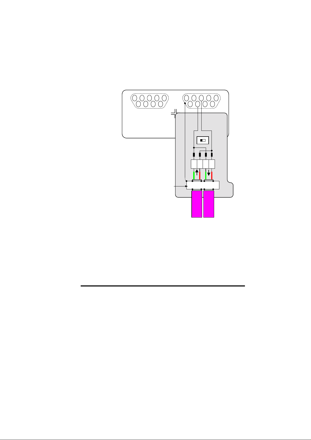
3.5 Profibus-DP Network Termination
The ter minati on resist or netw ork is not f itted i nternal ly on th e Unidri ve
Profib us-DP interf ace. It is th e installer ’s respons ibility to ens ure th at
both ends of eac h s ect i on of n etw or k c abl e are correct l y ter m in at ed.
The termination resistor network required is shown in the diagram
below.
Cable
clamp
+5V 0V ISOBA
It is very important in high-speed communications networks that the
network communications cable is correctly terminated. Failure to
terminate the network properly may mean that the network operates
with substantially reduced noise immunity, or in the worst case, the
network does n’t work at all.
Issue Number: 3 11
Page 12
3.5.1 ERNI Termination Connector
ERNI supply a sep arat e Prof ibus -DP conn ect or that has the appropr i ate
resist or n etwor k fit ted i nter nal ly. T h e termin ati on c onn ector is yell ow to
distinguish it from the non-terminated Profibus-DP connector.
6789
ERNI ERbic Profibus
Connector with vertical
cable outlet
Part No: 103658
3.5.2 Siemens Connector
The termination resistor network is fitted in the Siemens connector. The
resist ors can be s witch ed in or out of the circ uit as r equired us ing th e
Term ination Resistor Enable Switch .
Termination Resistor
Enable Switch
Siemens RS485
Profibus Connector
Part No: 6GK1 500 0EA02
12345
AB
DC
A
B
B
A
12345
6789
Cable Screen
Clamp
12345
6789
AB
DC
OFF
A
12345
6789
ON
B
B2A2B1A1
Cable Screen Clamp
12 Issue Number: 3
Page 13
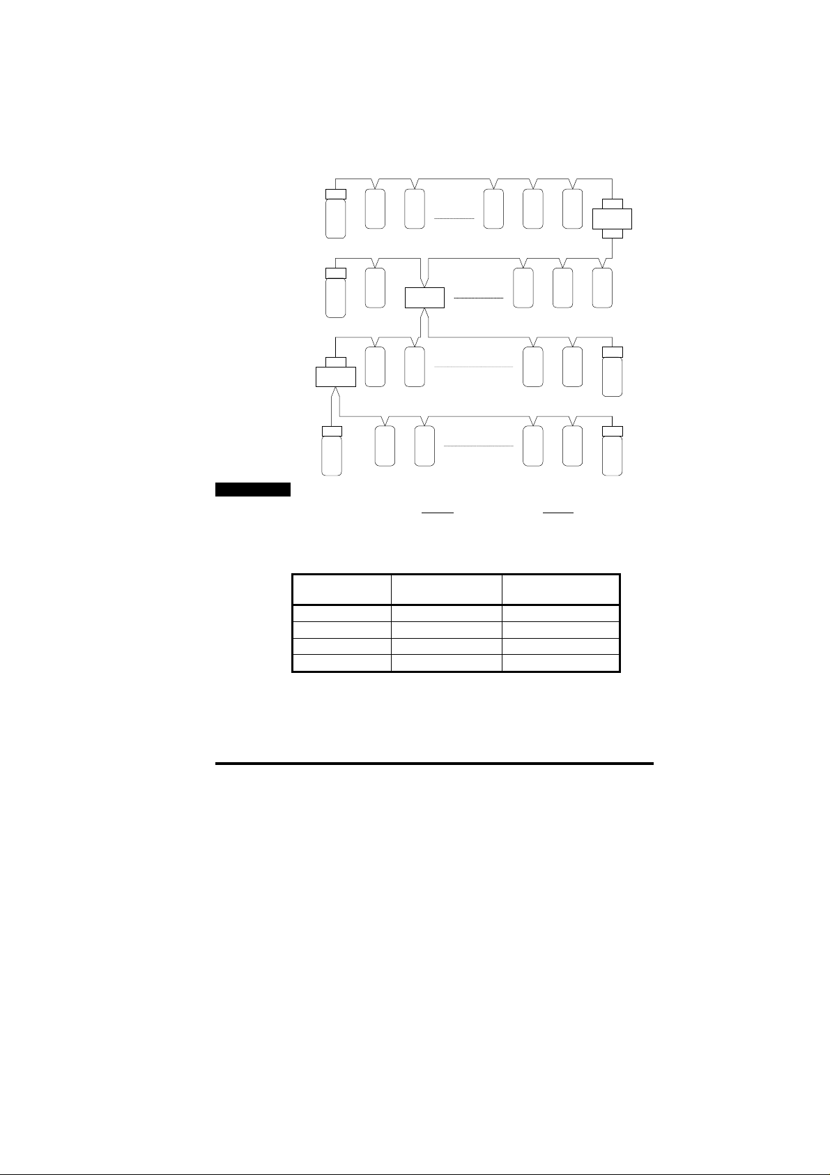
3.6 Maximum Network Length
The maximum number of nodes that can be connected to a single
Profib us-DP net work s egment is 3 2 nod es. Up t o 3 line r epeat ers m ay
be used t o extend th e network t o 4 segments , allowi ng a maxim um of
122 nodes on the network.
Section 1: max 31 stations + 1 repeater
NOTE
Rt
2 3 29 30 31
1
Section 2: max 30 stations + 2 repeaters
Rt
60
61
Rt
Repeater
Rt Rt
122
Repeater
Section 3: max 30 stations + 2 repeaters
62 63
Section 4: max 31 stations + 1 repeater
33
33 32
89
94121 120
90
93
Rt
Repeater
Rt
Rt
91
92
Terminating resistors (Rt) MUST be installed at BOTH ends of each
network segm ent.
The maxi mum length of cable f or each segmen t is determi ned by th e
data rat e at which the networ k must oper ate. The table bel ow gives a
summar y of the m a xi m um segment l ength for each d at a r ate.
Data Rate
(bits/sec)
Maximum Segment
Length (m)
Maximum Total
Network L engt h ( m)
9.6K to 93.75K 1200 4800
187.5K 1000 4000
500K 400 1600
1.5M 200 800
Issue Number: 3 13
Page 14
4 Getting Started
The Quick Start section shows the basic parameter configurations
required for the Profibus-DP interfaces to establish communications.
Cyclic and non-cycl ic d ata explan ati ons are given in c h apt er s 5 and 6.
NOTE
Parameters #20.01 to #20.20 and #20.50 are reserved for configuring
the Profibus-DPinterface, and should not be used in DPL programs.
4.1 Basic Communications Quick Start
Profibus-DP communications can be established with the Unidrive
Profib us -D P i nt er face simply by configuring the nod e address.
• Plug the Profibus-DP module into the Unidrive.
• Power up the Unidrive.
• Set the node address (#20.05) as required .
• Set #17.19 to 1 to store #20.05 and reset the UD70.
The Pr ofibus-DP i nterf ace will re-i nitialis e, and conf igure its elf with th e
new nod e addr ess . Th e dat a f ormat an d c onsist enc y ar e aut omati c ally
detected when the master controller initialises the network.
Function Unidrive Recommended Setting
Node Address #20.05 1 to 125
Data Rate Not displayed The data rate is automatically
Network Loss
Trip
#20.11 48
detect ed on P r of i bus -D P net w orks
4.2 Profibus-DP Node Address
Unidrive: #20.05
Every node must be given a unique network address. If a node is
assigned an address , and that ad dress alread y exists on the Profi busDP networ k, the node may prevent the network fr om operating. The
valid ran g e of ad dr esses is fr om 1 an d 12 5.
If an inval id node addr ess is set in #20.05, the Profibus-DP interf ace will
reject the c onfigured address , default to 125, and upd ate #20.05 with
the addr ess that is actu all y being us ed.
NOTE
Change s to #20.PP p arameters do not tak e effect in t he Profibus-D P
interface unti l the UD 70 has be en res et. See section 4.7.
14 Issue Number: 3
Page 15
4.3 Profibus-DP Data Rate
The Unidrive Profibus-DP interface will automatically detect the data
rate of the network, and synchronise to the master controller. Data
rates above 1.5 Mbits/sec are not supported. The Unidrive P rofibu s- DP
interface does not display the actual network data rate.
bits/sec
1.5M 93.75K
500K 19.2K
187.5K 9.6K
bits/sec
4.4 Data Format
The Unidrive Pr ofibus-DP int erfac e aut omatically det ects the required
data format when the master controller initialises the network. Data
consistency is optional, and is also detected during network
initialisation.
3 Cyclic Words with Mode 1 Non-Cyclic data (with or without
consistency) is the same data format as used on Mentor II and
Commander SE. Each cyclic data word is mapped to a Unidrive
parameter with default mappings as shown in the table below.
Cyclic
Channel
IN Word 0 Non-cyclic data word
IN Word 1 Status word
IN Word 2 Post-ramp speed reference
IN Word 3 Motor active current
OUT Word 0 Non-cyclic data word
OUT Wor d 1 Co n t rol wo rd
OUT Word 2 Digital speed reference 1
OUT Wo rd 3 Torque reference
Default Mapping Status
4.5 Network Status
Unidrive: #20.50
The status of the Profi bus-DP net work is displ ayed in #20.5 0, and can
be viewed on the disp l ay on the Unid ri ve.
#20.50 Status Description
>0 Network
healthy
0 Network is
not running
Issue Number: 3 15
Indic ates the nu mber of n et w ork cycles per
second, and the slave is exchanging data with
the master controller.
Indicates that th e n etwor k is not currentl y
running.
Page 16

4.6 Network Loss Trip
Unidrive: #17.14
If the Profibus-DP network stops operating, the interface will trip the
Unidrive on "tr60". The default time delay between network loss and
Unidri ve trip is 48ms , so the act ual delay t o trip will be between 4 8ms
and 96ms . (See sect ion 9.1 for mor e details.) T he master c ontroll er
will autom aticall y det ect that the sl ave node h as gone mis sing fr om the
networ k, and w ill update relevant s t at us r egis t er s .
NOTE
Changes to #17.PP parameters in the Unidrive do not take effe ct until
the UD70 h as b e en r es et. See section 4. 7.
4.7 Initialising Set-up Changes
UD70 (#17. PP) an d Prof ib us-D P (#20. PP) configur at ion par amet ers are
only read dur ing t he in iti alis ati on s equenc e of the U D70. T his prev ents
corruption of the configuration while parameters are being edited.
When p arameters h ave been conf igured, the UD 70 must b e reset to
implement any changes made to the configuration parameters.
To reset f rom the UD70, set #M M.00 to 1070 , and press the red RE SET
button on the Unidrive. Any changes made to the Profibus-DP
configu ration will n ow t ak e effect.
NOTE
Resetting the UD70 does not store the #20.PP configuration
parameters, so these changes will be lost when the Unidrive is
powered down. See section 5.6.2 for details on storing UD70
parameters.
16 Issue Number: 3
Page 17

5 Cyclic Data
NOTE
“OUT dat a” and “IN data” descr ibe the dir ection of dat a transfer as
seen by the PLC scanner.
5.1 What is Cyclic Data?
Cyclic data is a method data transfer that must be set-up during
network configuration, but is transmitted automatically once
configu rati on is c om pl ete. T he hi gh-s pe ed d ata tr ansf er is achie ved by
transmitting only a 16-bit data value for each cyclic channel over the
Profibus-DP network, and relying on local mapping information within
the Unidr ive t o ens ure th e corr ect d ata is s ent to the c orrect loc ations .
This method reli es on th e PLC progr am writi ng and read i ng data values
to and from the registers allocated to the node during network
configu r at i on, and the s ource and d es ti n at i on of I N and OUT d ata being
set-up correctly in the Unidrive itself.
The flexibility of the Unidrive Profibus-DP interface means that each
cyclic data OUT channel can be directed to any read-write Unidrive
parameter. S im il ar l y, each c yc lic d at a IN ch annel c an use an y Un idrive
parameter as a source of data.
NOTE
The mapping configuration cannot be changed dynamically, as the
UD70 must be re set bef ore change s to th e ma pping beco me ac tive.
5.2 What is Data Consistency
If a data format is selected that requires full data consistency, this
guarant ees that th e dat a on the Profib us is not upd ated with th e new
data val ues until ALL data words h ave been written in to the Profibus
buffer memory.
Consistent data may be important when using the 4-word non-cyclic
data f ormat. W ith out consist enc y, it is p ossib le for 2 of the 4 words to
go on one netw ork cyc le, wit h the dat a valu e updat ed on the next cycl e.
If the command was a write command, this could result in the previous
data value being written to the new parameter, and could have
disastr ous consequenc es.
Using dat a consist ency can oft en put restric tions on data manipu lation
within the master controller, and may require the use of special
functions within the master controller, and these can take longer to
execute. (Consult the supplier of the master controller for further
information.)
Issue Number: 3 17
Page 18

5.3 Profibus-DP Data Formats
The Unidrive Profibus-DP interface will auto-detect the data format
required during network initialisation. Consistency can be selected
when the master controller is configured.
Non-cyclic
mode
1 3 Full
1 3 None
1 3 Full 8 bytes with full co nsistency,
Cyclic
words
Consistency Comments
These m od es ar e sup p orted by
Mentor II and Commander SE
available for backwards
compatibility with older modules
5.4 Mapping Parameters on Unidrive
The mappin g for the c yclic data ch annels on the Unidriv e Profibus -DP
interface can be set from the Unidrive keypad using #20.PP
parameters.
The mapping method is similar to the method used for mapping
analogue inputs and outputs. The value entered in the mapping
parameter takes the form MMPP, where MM = menu number of the
target parameter and PP = parameter number of the target parameter.
NOTE
#20.01 t o #20.20, an d #20.50 are all reserved for Pr ofibus-DP set-up
an d config uration, and should not be used in DPL programs.
The default mapping values are shown in the table below.
Cyclic
Channel
IN Word 0 ---- Reserved for the non-cyclic data
IN Word 1 #20 . 07 #90.11 , fiel db u s status wo rd
IN Word 2 #20.03 #2.01, post-ramp speed reference
IN Word 3 #20.04 #4.02, torque-producing current
OUT Word 0 ---- Reserved for the non-cyclic data
OUT Word 1 #20.06 #90.11, fieldbus control word
OUT Word 2 #20.01 #1.21, digital speed reference 1
OUT Word 3 #20.02 #4.08, torque reference
NOTE
If a mapping parameter is set to an invalid value, e.g. destination
parameter i s read only, or param eter does not exist, th e Unidrive will
reset the mapping parameter (#20.PP) to its default value.
If a cyclic chann el is not req uired, s etting the m apping v alue to -1 will
disabl e it. The data word will sti ll be transmitt ed over the net work, but
the data value will not be written to any Unidrive parameter.
Mapping
Parameter
Default Mapping Status
18 Issue Number: 3
Page 19

NOTE
The cyclic dat a channel s do not us e decim al point s. For exa mple, th e
digital speed reference 1 (#1.21) has units of Hertz, accurate to 1
decimal p lace. To writ e a val ue of 24. 6Hz to #1.21, t he valu e must b e
transmitted as 246.
5.5 Internal 32-Bit Parameters on UD70
The Unidr iv e Pr ofibus -DP I nt erf ace has a s et of int ern al 32 -bit r eg ist ers
in the UD70. These are addressed as _Pxx%, _Qxx%, _Rxx% or
_Sxx% fr om the DPL progr am, and the _Qxx% registers are used with
the internal position controller in the UD70.
A 32-bit c yc lic channel can be created for IN data, O UT data or both, by
combin ing c yclic chann els 2 an d 3. This allows f ull 32-b it valu es to b e
directl y transf erred b etween t he UD70 and th e contr olling PC or PLC.
(See the “User’s Guide” for the UD70 for more information.)
The 32-b it cyclic ch annel is confi gured by mapp ing IN or OUT cyclic
data ch annel 2 (#2 0.01 or #2 0.03) t o a 32 bit regis ter, an d settin g the
mapping for IN or OUT cyclic data channel 3 (#20.02 or #20.04) to -2.
Channel 3 will contain t he data high w ord (upper 16 b its of the 32 -bit
regist er) and c han nel 2 c ont ains t he d ata low wor d (low er 16 b its of the
32-bit register. )
The 32-bit r egisters are addr essed as param eters in menu 70 to menu
73. (See table below.) To map a cyclic channel to one of these
regist ers, the param eter refer ence must b e entered in th e appropri ate
mappin g p aram eter.
Registers Parameter
_P00% - _P99% #70.00 to #70.99
_Q00% - _Q 99 % #7 1.0 0 to #71.99
_R00% - _R99% #72.00 to #72.99
_S00% - _S99% #73.00 to #73.99
NOTE
If the mapping for both cyclic channel 2 and cyclic channel 3 are
directed to 32 bit registers, only the low 16 bits of each register will be
written to or read from.
Reference
5.6 Storing Parameters
Although any changes to the mapping will take effect after a UD70 reset
sequence, the new values must be stored in non -volatile memory if they
are to be rest or ed au tomatic all y w h en the Interf ac e is ne xt pow ered up.
5.6.1 Saving Unidrive Parameters (Menu 1 to 19)
To initiate the Unidrive parameter save sequence, set #MM.00 to 1000
and press the red RESET but t on on the keypad.
All parameters in these menus are saved in the EEPROM in the
Unidri ve. If t he Unidrive Pr ofib us- DP in terf ac e is repl ac ed, th e Unidr i ve
Issue Number: 3 19
Page 20

will ret ain all val ues in m enu 1 thr ough m enu 19 when t he Unidr ive is
next powered up.
5.6.2 Saving UD70 Parameters (Menu 20 and Internal)
To initiate the non-volatile save sequence for these parameters, set
#17.19 t o 1. The UD 70 will then s tor e menu 20 and the int ernal 3 2-bit
parameters, clear #17.19 back to zero and completely reset itself.
All menu 20 parameters and internal 32-bit parameters (_Pxx% and
_Qxx%) are stored in the FLASH memory of the UD70. If the Unidrive
Profi bus-DP interface is replaced, the menu 20 parameters may need to
be re-c onfigured. If t h e r eplacemen t m od ule has been us ed be fore, the
stored values may be different from the normal default settings.
The UD70 can also be configured to store these parameters
automatically when the Unidrive powers down. The store routine is
triggered when an under-voltage (UU) trip occurs. Set #17.20 to 1,
store the Unidrive parameters and reset the UD70 to enable this
feature.
5.7 Mapping Conflicts
When th e mappin g paramet ers f or the Pr ofibus -DP c yclic chann els ar e
set, c are must b e taken t o ensure th at there are no clas hes with the
mapping of the analogue and digital inputs within the Unidrive. The
Unidri ve Profibus -DP inte rface wil l not indic ate any conf lict of mapp ing
paramet ers. This only appli es to anal ogue and dig ital inpu ts, and OUT
data on the Pr of ibus-DP net work.
If a num erical parameter is written to f rom two different sources, the
value of this parameter will depend entirely upon the sca n times for the
analogue or digital input and the Profibus-DP network. Further
confusion may be caused due to the update rate of the display. A
parameter may appear to be steady at a particular value, but
occasion ally gl itch in the value wil l be seen. I n reality, t his val ue may
be chang in g c onti nu ous ly, lead i ng to erratic b eh avi ou r .
Function Mapping
Parameter
Analogue I/P 1 #7.10 Logic O /P 2 #9.20
Analogue I/P 2 #7.14 Motor ised Pot O/P #9.25
Analogue I/P 3 #7.18 Binary Summer #9.33
Digital I/P 1 #8.10 Comparator 1 O/P #12.07
Digital I/P 2 #8.13 Comparator 2 O/P #12.17
Digital I/P 3 #8.16 Reference Input #13.06
Digital I/P 4 #8.19 PID O/P #14.16
Digital I/P 5 #8.21 Cyclic OUT Word 1 #2 0.06
Digital I/P 6 #8.23 Cyclic OUT Word 2 #20. 0 1
Logic O/P 1 #9.10 Cyclic O U T Word 3 #20.02
Ensure th at eac h Unidri ve param eter in t he tab le abov e has a diff erent
value programmed. A value of 0 will disable analogue and digital
inpu ts, and -1 will disable the cyclic data channels.
Function Mapping
Parameter
20 Issue Number: 3
Page 21

5.7.1 Control Word Mapping Conflicts
The control w ord pr ovid es a method of writ in g to multipl e bit param eter s
using one dat a word. If one of the cyclic data channels is writing to the
control w ord, th e followi ng bi t paramet ers for eac h Unidr iv e must n ot be
controll ed by a ny digi tal inpu ts.
Function Param
Enable #6.15 Preset ref selec t bit 1 #1. 46
Run Forwards #6.30 Application bit #18.3 1
Jog #6.31 Applic ati on bi t #1 8.3 2
Run Reverse #6.32 Application bit #1 8.3 3
Preset ref selec t bit 0 #1.45
Function Param
5.8 Fieldbus Control Word for Unidrive
NOTE
This section assumes that the Unidrive is configured to use the
default Wire Proof PLC sequ encing mode (#6.04 = 4). If PLC mode is
selected (#6.04 = 3), the control word mapping is slightly different.
Refer to section 9.2 for details.
The Con trol W ord is an efficient way of r emot ely contr olli ng the m otion
of a Unidri ve. Each bit in the contr ol word h as a p ar ticular func ti on, an d
provides a method of controlling the function of the Unidrive (RUN,
JOG, etc.) with a single dat a word. The contr ol word is address ed in
the UD70 b y writ in g to #9 0.11.
b15 b14 b13 B12 b11 b10 b9 b8
M6 M5 #18.33 M3 M2 M1 M0 #18.32
b7 b6 b5 b4 b3 b2 b1 b0
#18.31 #1.46 #1.45 TRIP RUN
REV
The bits shown as “Mx” are individual mask bits that allow the
corresp on ding "bx” to be masked , i.e. the MASK bits determi ne wh eth er
or not the data bit is written through to the corresponding parameter.
JOG RUN
FWD
ENABLE
Issue Number: 3 21
Page 22

#18.33
#18.32
#18.31
Trip
b0b1b2b3b4b5b6b7b8MOM1M2M3b13M5M6
1
0
1
0
1
0
1
0
1
0
1
0
#6.15
#6.30
#6.31
#6.32
#1.46
#1.47
If mask bits M0 and M1 are set to 1, ENABLE and RUN FWD are
updated with the values of b0 and b1 (either 0 or 1) every time the
control word value is received. JOG and RUN REV will not be up d ate d,
even if the val ues of b 2 and b3 chan ge, bec ause th eir mask bits ( M2
and M3) are n ot s et to 1. If M0 and M1 ar e res et t o 0, th e valu es in b0
and b1 will NOT be written to ENABLE and RUN FWD, and these
parameters will remain set to their current state.
The TRIP bit (b4) will cause a “tr52” trip when set to 1, but the trip
cannot be cleared until the TRIP bit (b4) has been reset to 0.
Paramet ers #18.3 1 to #18.33 are gener al user p arameters and do n ot
have mask bits.
Bit Function Description
0 ENABLE Set to 1 to put the Unidrive in READY mode. (The
hardware ENABLE must also be present.) The RUN
FWD, JOG and RUN REV bits will have no effect
unless t h e ENABLE bit is set to 1. The Unidriv e
outputs are disabled i mmediatel y wh en th e EN AB L E
bit is reset to 0, and the motor will coast to stop
1 RUN
FWD
Set to 1 to run the motor in the forwards direction.
Reset to 0 to dece lerate the motor to a controlled
stop before the Unidrive output stage is disabled
2 JOG Set to 1 with RUN FWD or RUN REV bit also set to
jog th e mot or i n th e appropriate direction. The
Unidri ve will ramp the m otor to the normal speed or
stop when the JOG bit is reset to 0, depending on the
status of the RUN FWD and RUN REV bits.
22 Issue Number: 3
Page 23

3 RUN
REV
4 TRIP Set to 1 to trip the Unidrive on “tr52”. The TRIP bit
5 #1.45
6 #1.46
7 #18.31 User application bit
8 #18.32 User application bit
9 M0 ENABLE mask bit
10 M1 RUN FWD mask bit
11 M2 JOG mask bit
12 M3 RUN REV mask bit
13 #18.33 User application bit
14 M5
15 M6
Some exam pl e contr ol wor ds for Wir e-Pr oof P LC m ode are gi ven in th e
table below.
b15-b12 b11-b8 b7-b4 b3-b0 Value Action
0000 0010 0000 0000 0x0200 Drive disable
0001 1110 0000 0001 0x1E01 Enabled + stopped
0001 1110 0000 0011 0x1E03 Enabled + run fwd
0001 1110 0000 1001 0x1E09 En abled + run rev
0001 1110 0000 1101 0x1E0C Enabled + jog rev
Set to 1 to run the motor in the reverse direction.
When res et to 0, the Unid r i ve wil l decelera te the
motor to stop before the outputs are disabled
must be reset to 0 before the Unidrive can be reset.
Preset Reference Select. These bits are used to
sele ct the digital speed references used. Refer to the
Unidrive User Guide for more information.
Mask bits for the Preset Reference Select bits
5.9 Fieldbus Status Word for Unidrive
The status word is an efficient way of remotely monitoring and
diagnosing the status of the Unidrive. Each bit in the status word
indic ates the st atus of a f unction of the Un idrive, e.g. At Sp eed, Dri ve
Healthy, etc. T he stat us word is address ed in th e UD70 b y writing to
#90.11.
b15 b14 b13 b12 b11 b10 b9 b8
X #10.15 #10.14 #10.13 #10.12 #10.11 #10.10 #10.09
b7 b6 b5 b4 b3 b2 b1 b0
#10.08 #10.07 #10.06 #10.05 #10.04 #10.03 #10.02 #10.01
The tab l e below sh ows the particular status of t h e Unidriv e indic ated b y
each bit when set to 1.
Issue Number: 3 23
Page 24

Bit Parameter Description
0 #10.01 Drive healthy
1 #10.02 Drive running
2 #10.03 Zero speed
3 #10.04 Running at or below min speed
4 #10.05 Below set speed
5 #10.06 At speed
6 #10.07 Above set speed
7 #10.08 Load reached
8 #10.09 In current limit
9 #10.10 Regenerating
10 #10.11 Dynamic brake active
11 #10.12 Dynamic brake alarm
12 #10.13 Direction commanded
13 #10.14 Direction running
14 #10.15 Mains Loss
15 Not used
5.10 Disabling Cyclic Data Channels
Set the appropriate channel mapping parameter to -1, and reset the
Unidrive Profibus-DP Interface.
If an application only requires 2 cyclic data channels, the remaining
chann el can b e disab led. This means that t he dat a recei ved fr om th at
channel will not be written to any Unidrive parameter. It does not
actually remove the channel from the Profibus-DP network.
24 Issue Number: 3
Page 25

6 Non Cyclic Data
The non-cyclic d ata ch an nel provides a meth od for the mast er c ontroller
to read f rom or wr ite to an y paramet er wit hin the Dr ive. This c hannel
can be used for single infrequent data transfers, or uploading and
download ing param eter sets to or from a particul ar nod e.
Non-cyc lic d ata acc ess t o Unidr ive p aramet ers is c ontr olled entir ely by
the mas ter contr oller pr ogram, and is not c onfigur ed in an y way wh en
the Profibus-DP network map is defined.
The Unidrive Profibus-DP interface currently provides the CT Single
Word Format of non-cyclic data. This mode is also available in the
Mentor II and Commander SE Profibus-DP interfaces.
NOTE
The non-cyclic data channel does not use decimal points. For
example, the digital speed reference 1 (#1.21) has units of Hertz,
accurat e to 1 de cimal pl ace. To wri te a valu e of 24.6H z to #1. 21, the
value must be tr ansmitt ed as 246.
6.1 CT Single Word Format
The CT Sin gle W ord Format of non-c yclic d ata uses one word f or noncyclic data. The non-cyclic sub-protocol requires a specific sequen ce of
4 words or "t elegr ams" to i mp lem ent th e par am eter ac c ess. E ach noncyclic word or telegram is split into 2 bytes to implement the subprotocol, with the high byte containing the control codes for each
telegram, and the low byte containing the data for each telegram.
b15 b14 b13 b12 b11 b10 b9 b8
R/W Error X X Stamp number
b7 b6 b5 b4 b3 b2 b1 b0
Data b yte
NOTE
If “littl e en dian” data format has been selected , the bytes th at fo rm the
non-cyclic data wor d MUST b e swapped BEFOR E the non- cycli c data
word is transferred to the Profibus. See section 9.5.
Issue Number: 3 25
Page 26

NOTE
Bit Function Values Description
0 to 7 Data 0 to 255 Depending on the stamp number of
8 to 11 Stamp
number
12, 13 Not Used These should be set to 0.
14 ERR 0 = Data OK
15 R/W 0 = Write
X = don’t car e. Gener ally, t hese bits s hould b e set to 0. If a mes sage
is aborted part w ay thr ough, th e non-c yclic OU T wor d shoul d be res et
to 0. This will reset the non-cyclic state machine, and allow the
message sequence to be restarted.
0 to 4 Indicates the stamp number of the
1 = Error
1 = Read
the telegram, this byte contains the
menu or parameter number, or data
high or low byt e.
word. This shows which part of the
message is currently in progress.
Setting the stamp number to 0 resets
the internal non-cyclic sate machine
Indic ates the suc cess or failure of the
messag e. Fa ilure could occur if the
parameter does not exist, or is a
read- onl y or write-only paramet er .
Defines whether the data word is part
of a READ or WR I TE c ycl e i s in
progress.
26 Issue Number: 3
Page 27

6.1.1 Reading parameters using Mode 1
To read parameters using the non-cyclic channel, the following
“telegrams” must be transmitted to construct the final message.
• T el egram 1 Define menu numb er.
• Telegram 2 Define parameter number.
• T elegram 3 Request high data byte.
• Telegram 4 Request low data byte.
Start
READ
Send first telegram
to OUT word 0
Read IN
word 0
TELEGRAM 1
Tx_Stamp_No =
Rx_Stamp_No?
Tx_Stamp_No
= 2?
Check status
of ERR bit
ERROR. Check paramter exists, data
is in correct range, and parameter is
The follow ing examp le tel egr ams sh ow how to read th e data val ue fr om
#3.02 i n the Unidriv e.
The first telegram from the master indic ates a READ c ycle, and the
stamp number is 1. The data byte would contain the menu number for
the parameter that is to be read.
Bit b15-b12 b11-b8 b7-b4 b3-b0
Value 1XXX 0001 0000 0011
Data word = 0x8103 Stamp number = 1 Menu = 3
When th e firs t telegr am h as been r eceiv ed and p roc essed i n the sl ave
node, it is mirr ored i n th e non-c yclic IN word back t o the P LC. T his is
the sig nal t o th e m aster c ontr oll er pr ogr am t hat t he f irst t el egram of th e
messag e has been r eceived and und erstood , and the s econd t elegr am
can be trans m itted.
Yes
Yes
1
Read/Write
No
0
No
Send next
telegram to
OUT word 0
Send telegram 3 to
OUT word 0
Read IN
word 0
Tx_Stamp_No =
Rx_Stamp_No?
Yes
Store data
byte
Tx_Stamp_No
Calculate
data value
END OF
SEQUENCE
= 4?
No
Yes
No
Send next
telegram to
OUT word 0
Issue Number: 3 27
Page 28

TELEGRAM 2
TELEGRAM 3
The second telegram from the master also indicates a READ cycle, but
the stamp number is now 2. The data byte would contain the parameter
number for the parameter that is to read.
Bit b15-b12 b11-b8 b7-b4 b3-b0
Value 1XXX 0010 0000 0010
Data word = 0x8202 Stamp number = 2 Parameter = 2
When the second telegram has been received and processed in the
slave n ode, it is mirr or ed in t he n on-c yclic IN w ord. T his is t he si gna l to
the master controller program that the second telegram of the message
has been received and understood, and the third telegram can be
transmitted.
The thir d telegr am fr om the m aster act s as th e indic ation to th e slave
node to send the data high byte from the requested parameter. The
data byte is not used in this telegram, and should be set to 0.
Bit b15-b12 b11-b8 b7-b4 b3-b0
Value 1XXX 0011 XXXX XXXX
Data word = 0x8300 Stamp number = 3 Data high byte = XX
When th e thir d t elegr am has been r ec eiv ed an d pr ocess ed i n t he sl ave
node, th e node wi ll mirr or the st amp nu mber in th e non-c yclic I N word,
and load the high byte of the parameter value into the data byte.
Bit b15-b12 b11-b8 b7-b4 b3-b0
Value 10XX 0011 0000 0101
Data word = 0x8305 Stamp number = 3 Data high byte = 0x05
If an invalid parameter was specified in telegrams 1 and 2, e.g.
parameter is write only, or does not exist, the Profibus-DP interface will
set the ERROR bit to 1 (b14 = 1). The data bits will have no
significance.
Bit b15-b12 b11-b8 b7-b4 b3-b0
Value 11XX 0010 XXXX XXXX
Data word = 0xC200 Stamp number = 2
If an error is report ed, it is r ecomm ended th at th e non-cyc lic dat a word
is set to 0 to ensure that the non-c yclic state machine is completely
reset, and ready for the ne xt non-c ycl ic RE AD or WRITE sequ ence.
28 Issue Number: 3
Page 29

TELEGRAM 4
The four th telegr am fr om th e master acts as th e indic ation t o the slav e
node to send the data high byte from the requested parameter. The
data byte is no t used in this telegram and s h ould be set to 0.
Bit b15-b12 b11-b8 b7-b4 b3-b0
Value 1XXX 0100 XXXX XXXX
Data word = 0x8400 Stamp number = 4
When the fourth telegram has been received and processed in the
slave n ode, th e node will mirr or t he stam p num ber in th e non-c yclic IN
word, and l oad t he low byte of t he parameter value into the data byte.
Bit b15-b12 b11-b8 b7-b4 b3-b0
Value 1XXX 0100 1101 1100
Data word = 0x84DC Stamp number = 4 Data low byte = 0xDC
Speed feedback = (high data byte * 256) + low data byte
= (0x05 * 0x100) + 0xDC
= 0x05DC
= 1500 rpm
6.1.2 Writing parameters using Mode 1
To write to parameters using the non-cyclic channel, the following
telegrams must be sent on each network cycle to construct the final
message.
• T el egram 1 Define menu numb er.
• Telegram 2 Define parameter number.
• T el egram 3 Set data high byte.
• T el egram 4 Set data low b yte.
Start
WRITE
Send first telegram
to OUT word 0
Read IN
word 0
Tx_Stamp_No =
Rx_Stamp_No?
Yes
Tx_Stamp_No
= 4?
Yes
No
No
Send next
telegram to
OUT word 0
Check status
of ERR bit
Parameter
written OK
END OF
SEQUENCE
1
ERROR
Check paramter
exists, and that it is
a Read/Write
parameter
Issue Number: 3 29
Page 30

TELEGRAM 1
TELEGRAM 2
TELEGRAM 3
The following exam p l e t el eg rams show ho w to wri te a value o f 120.0 H z
(0x04B 0) to #1. 21 in the Uni drive.
The first telegram f rom the m aster in dicates a WRITE cycle by setting
the R/W bit to 0. The stamp number is set to 1. The data byte contains
the menu nu m b er f or the p ar am et er that is t o be wr itten to.
Bit b15-b12 b11-b8 b7-b4 b3-b0
Value 0XXX 0001 0000 0001
Data word = 0x0101 Stamp number = 1 Menu = 1
When th e firs t telegr am h as been r eceiv ed and p roc essed i n the sl ave
node, it is mirr ored in t he non-c yclic IN word. T his is the si gnal t o th e
master controller program that the first telegram of the message has
been received and understood, and the second telegram can be
transmitted.
The second telegram from the master also indicates a WRITE cycle, but
the stamp number is now set to 2. The data byte contains the
parameter number for the parameter that is to be written to.
Bit b15-b12 b11-b8 b7-b4 b3-b0
Value 0XXX 0010 0001 0101
Data word = 0x0215 Stamp number = 2 Parameter = 21
When the second telegram has been received and processed in the
slave n ode, it is mirr or ed in t he n on-c yclic IN w ord. T his is t he si gna l to
the master controller program that the second telegram of the message
has been received and understood, and the third telegram can be
transmitted.
The third telegr am f rom the mast er h as the stam p nu m ber set to 3. The
data bits contain the data high byte for the parameter being written to.
Bit b15-b12 b11-b8 b7-b4 b3-b0
Value 0XXX 0011 0000 0100
Data word = 0x0304 Stamp number = 3 High data byte = 0x04
When th e thir d t elegr am has been r ec eiv ed an d pr ocess ed i n t he sl ave
node, it is mirr ored in th e non-c yclic IN word. Th is is th e signal t o the
master c ontroller program th at the third t elegram of the message h as
been received and understood, and the fourth telegram can be
transmitted.
30 Issue Number: 3
Page 31

TELEGRAM 4
The f ourth telegr am from th e master has the st amp number set to 4.
The data bits contain the d ata low byte for the paramet er that is being
written t o.
Bit b15-b12 b11-b8 b7-b4 b3-b0
Value 0XXX 0100 1011 0000
Data word = 0x04B0 Stamp number = 4 Low data byte = 0xB0
When the fourth telegram has been received and processed in the
slave n ode, i t wil l writ e th e dat a (#1. 21 = 1200 ) as tr ans mitt ed, ig n oring
the d eci m al p oint. I f t he operation is successful, the ERR bit is reset to
0 and the t eleg ram is refl ected i n th e non-cyclic IN word.
Bit b15-b12 b11-b8 b7-b4 b3-b0
Value 00XX 0100 1011 0000
Data word = 0x04B0 Stamp number = 4 Low data byte = 0xB0
If there was a pr oblem with writ ing the data to the d efined parame ter,
e.g. par amet er is read on ly, d oes not exist, or d ata is out of r ange, th e
ERR bit is set to 1.
Bit b15-b12 b11-b8 b7-b4 b3-b0
Value 01XX 0100 XXXX XXXX
Data word = 0x4400 Stamp number = 4
6.2 Profibus-DP Set-up using Non-Cyclic Data
The Unidr i ve P rofib us- DP interface c an als o b e c onf igured vi a th e n oncyclic d ata channel. Menu 20 in the Unidri ve contains t he paramet er
values currently being used, and these can be modified as required.
Cyclic d ata map ping p aram eters c an be edi ted via the n on-c yclic dat a,
but changes made to the data mapping will not take effect until the
UD70 has been reset.
Setting #1 7.19 to 1 wil l store th e mapping c hanges in th e Profibus -DP
interface, and r es et t h e Profibus-D P interf ac e. T h e P rofibus -D P master
controller may detect an brief error while the Unidrive Profibus-DP
interface resets and re-configures itself.
The par ameter s lis ted b elow are the p aram eters t hat c an b e writt en t o
configu r e th e Prof i b us - DP int er face.
Param Default Description
#20.07 #90.11 Not used
#20.03 #2.01 IN Channel 2 Mapping
#20.04 #4.02 IN Channel 3 Mapping
#20.06 #9 0.1 1 OUT Ch ann el 2 M apping
#20.01 #1.21 OUT Channel 3 Mapp ing
#20.02 #4.08 Load Option Defaults
Issue Number: 3 31
Page 32

#20.11 200 Trip Delay Time (ms)
Specifi es the time- out peri od for the Profibus DP netw ork . If n o n etw ork mess ag es ar e
received in this time period, the network loss
trip is invoked. (See section 9.1)
#20.13 0 Endian Format Select
See section 9.5
#17.14 0 Network Loss Trip Enable
#17.19 0 UD70 St ore and Reset
The param eters listed in t he table below r eturn inf ormation about the
Profibus-DP interface. Writing to these parameters will not affect the
operati on of th e nod e.
Param Description
#20.14 Option ID Code
Indicates the fieldbus type, flavour and hardware version.
(See section 8.1)
#20.15 Software Version Vxx.yy
Indicates the firmware version fitted to the Profibus-DP
interface. (See section 8.2)
#20.50 Fieldbus Diagnostic
Indic ates the number of m es s age b ein g pro cessed by t he
Unidri ve Profibus- DP . ( See section 8.6)
#17.02 Syst em F i l e V ersi on ( S ee s ect ion 8.3)
All param et ers f r om #2 0.01 t o #20. 20 ar e r eser ved for use t o c onf igur e
new features that may be added in future updates of the Unidrive
Profibus-DP interface. Unpredictable behaviour of the Profibus-DP
interface may resu lt if t he se parameters are used fo r other pur poses.
32 Issue Number: 3
Page 33

7 GSD Files
7.1 What are GSD Files?
GSD files are text files that are used with the Profibus-DP network
configuration software. They contain information about the device
capabilities, such as supported data rates, delay timings, supported
data formats, etc.
GSD files are not actually download ed to the PLC or sc anner. The
inform ation th ey contai n is used when th e network c onfigur ation fil e is
generated, but they are necessary and are only used during network
configuration. They must usually be installed into the network
configu ration sof tware, or c opied t o a specif ic director y. Ref er to the
software documentation for instructions about installing GSD files.
Control Techniqu es ca nnot offer specific techni cal s upport on any of t he
softwar e p ac k ag es av ai l able for conf ig uring Profib us - DP net w or ks .
NOTE
A device cannot be included in the configuration for a Profibus-DP
network without an associated GSD file.
7.2 Unidrive GSD File
A GSD f ile is avail able f or th e Unid rive P rofibus -DP interf ace, and c an
be obtained from your local Control Techniques Drive Centre, or the
Profibus web site at "www.profibus.com". This file contains a full
descrip tion of th e perf ormanc e cap abiliti es of t he Un idri ve Prof ibus- DP
interface.
Most configuration tools for Profibus-DP will group slaves together,
depend ing on wh at type of devic e th ey ar e. Th e Unidr i ve can b e foun d
under heading "ADDITIONAL FIELD DEVICES", sub-heading
"DRIVES".
Drive Filename Version
Unidrive CTU_3345.GSD V5.0
Commander SE CTSE04FA.GSD V1.2
Issue Number: 3 33
Page 34

7.3 Data Consistency
Data cons is tency pr ovi des a met h od of ens ur i ng that all d ata is updated
at the sam e tim e, thus prevent in g an y f or m of d ata sk ew .
Using dat a consist ency can oft en put restric tions on data manipu lation
within the master controller, and require data bytes or words to be
written in a certain order. Using data consistency can increase the
master controller cycle time, so it should only be used if really
necessary. (See section 5.2).
7.4 Profibus-DP Data Formats
All data formats can be set to have full data consistency or no data
consistency. T he fi r st cycl i c da ta word is always th e c ontrol word.
Non-cyclic
mode
1 3 Full
1 3 None
1 3 Full 8 bytes with full consistency,
When th e m as ter initi alises the n et w ork , it wil l tr ansmit th e config ur at i on
byte to eac h slave. If t he configur ation byt e matches on e of the thr ee
modes above, the s l ave will automatically configure itself f or this t ype of
data.
If the telegram does not match any of the above data formats, the node
will not be initialised and the master will indicate that there is an error on
the network.
Cyclic
words
Consistency Comments
These m od es ar e sup p orted by
Mentor II and Commander SE
available for backwards
compatibility with older modules
34 Issue Number: 3
Page 35

8 Diagnostics
NOTE
The information from the parameters described below should always
be noted before cont a ctin g Contr ol T echniq ue s for te ch ni cal su ppor t.
8.1 Fieldbus Code
Unidrive: #20.14
The fieldbus code identifies the hardware level in the Profibus-DP
interface. This information is vital when trying to determine what
upgrad es can be performed on old er modul es.
The identif ication of the high-sp eed com munic ations opti on modul e can
be read fr om #20.1 4 on th e Unidri ve displ ay. This nu mber is shown in
the form X Y Z, where X is the fieldbus typ e, Y is the fieldbus flavour, and
Z is the hardware revision level.
#20.14 Fieldbus
Type
100 1
(Profibus) 0 (DP) 0 (UD73A Issue 1 and UD73B Issue 1)
8.2 Firmware Version
Unidrive: #20.15
The vers ion of f irmwar e fitted to th e Profib us-DP i nterf ace c an be read
from #20.15. The Hardware Revision column shows the hardware
levels that c an ac cept each vers i on of firmware.
#20.15 Firmware
202 V2.02.00 0
204 V2.04.00 0
205 V2.05.00 0
Version
Fieldbus
Flavour
Hardware
Revision
Hardware Revision
Issue Number: 3 35
Page 36

8.3 System File Version
Unidrive: #17.02
The system file ins talled in th e UD70 mus t be the correc t file for the
communications option installed. The system file for the Unidrive
Profibus-DP interface is “IBSPROFI.SYS”.
The system file that must be installed can depend on the level of
hardw are and f irm war e in th e modul e. In g ener al, new s ystem f il es ar e
backwar d compati ble with old er versions of firmware and har dware, but
there may be some limitations when upgrading older modules. (See
sections 8.1 and 8.2.)
The system file version can be read from parameter #17.02 on the
Unidrive.
Firmware Hardware
Revision
V2.02.00 0
V2.04.00 0
V2.05.00 0 V2.08.00 Certified by the PROFIB U S
System
File
V2.07.03
or later
NOTE
System files can be downlo aded usi ng the WINFLA SHER utilit y, which
can be obtained from you local Drive Centre.
8.4 Node Address
Unidrive: #20.05
Every Pr ofibus-D P node mus t be assi gned a u nique nod e address . If
two or more nodes have the same address, this will c ause a conflict
when the master attempts to initialise the network.
Ideall y, the node addr ess should be conf igur ed on each node BEFO RE
any a ttempt is made to conne ct it to the network.
Comments
Nutzerorganisation (PNO)
8.5 Network Data Rate
Unidrive: N/A
The Unidrive Profibus-DP interface will automatically detect the data
rate of th e n et w ork, and synchronise to th e mas ter controll er . Har dware
Revision 0 supports a maximum data rate of 1.5 Mbits/sec. The
Unidrive Profibus-DP interface does not display the network data rate.
36 Issue Number: 3
Page 37

8.6 Network Status
Unidrive: #20.50
#20.50 on Uni driv e indic at es th e num ber of valid mess ages p er s econ d
being rec eived b y the node. The Pr ofib us- DP netw ork mast er contr oll er
addresses every node on the network once per network cycle, and
exchan g es t h e c onfigured am ount of information. If a n e twor k has been
correctl y wired , screened and term inated, th ere will b e very few errors
occurri ng, an d the numb er of m essag es per s econd dis played on each
node should be the same. #20.50 is only updated once per second.
8.7 No Data Transfer
If data is not being transferred from the master controller to the
Unidrive, make the fo llowing c hecks:
• T he mapping param eters ha ve been progr ammed corr ectly. If an
invalid m app in g w as entered, it will hav e be en r eset to 0.
• Check that there are no mapping parameter conflicts, i.e. an
analogue input is not trying to control the same parameter as a
cyclic OUT channels.
8.8 Unidrive Trip Codes
The trip codes listed below may be caused by the Profibus-DP
interf ac e. Oth er tri ps may occur if a DP L prog r am is load ed. For a ful l
list of UD70 trips, refer to the UD70 User Guide
Trip
Error
Code
tr52 This code indicates that the trip originated from the setting of
bit 4 in the control Word
tr56 The UD70 does not contain the correct operating system for
the detected hardware. Download the system file
“IBSPROFI.SYS”. If the trip persists, ensure that the UD73A
and UD70 b oar ds inside the mod ule are properl y cl ip p ed
togeth er . (This should onl y b e at t emp ted by suitab l y qu alif ied
personnel!!)
tr57 An illegal operating system call has been made, e.g. WRNET.
CTNet commands cannot be us ed wit h Profi bus - D P
tr60 This trip indicates that loss of the Profibus-DP network has
been det ect ed . This can be caused by disconn ecting the
node form the network, a bad cable connection, or by
resettin g or st opping the net w or k master controller
See section 9.3 for details on how to reset the Unidrive using the
Profibus-DP network.
Issue Number: 3 37
Page 38

9 Advanced Features
9.1 Network Loss Trip
Unidrive: #20.11
0 = trip dis abled 16 to 992 = trip delay t i me (in m s )
The Profibus-DP interf ace counts th e numb er of val id network c ycles
received in a time period specified by #20.11. The trip is triggered if no
messag es are recei ved in a given s ample peri od, and mess ages wer e
received in th e previ ous s ample period. T he d efault s ettin g for #2 0.11
is 48ms. T he UD7 0 Gl obal R un-Ti me T rips also ha ve to b e enabl ed by
setting # 17. 14 to 1.
Sample
points
#20.11
NOTE
Messages
per sec
Profibus-DP stops
communicating here
As can be s een fr om the diagr am, th e actual ti me fr om net work los s to
Unidri ve tri p will ran ge fr om #20.1 1 ms to 2 * #20.1 1 ms. If the tri p ti me
is set too low, spurious net w or k loss trips may be seen.
The actual network loss trip time depends entirely on the number of
messages per second being received under normal operation. As a
rough gu i de , t he net work loss trip time (#20 . 11) should b e set suc h t hat
a minimu m of 5 mess ages will be recei ved in any given sam ple period
under normal operating conditions.
The network loss trip delay is specified in ms, but the time set will be
rounded up to the nearest multiple of 16ms. Hence, if the time delay is
set to 100ms, this will be rounded up to 112ms.
Unidrive trips
on "tr60"
Time
(ms)
38 Issue Number: 3
Page 39

9.2 Unidrive Sequencing Mode 3
The def au lt s equ encing m ode for Unid r i ve is t h e Wire -P r o of P LC M o de.
If PLC Mod e is selected (#6.04 = 3), the seque n c in g bits (#6. 30 - #6. 32)
have slightly different functions.
Control
Word
b0 #6.15 Enable Enable
b1 #6.30 0 Run
b2 #6.31 1 Jog
b3 #6.32 2 Reverse
ENABLE the displ ay will sh ow "Inh" wh en set at 0 , and depen ds on
JOG the jog bit must be s et, along with the appropr iate run an d
To reset th e Unidr ive us ing th e Profi bus- DP n etw ork, us e the non-c y clic
channel to set #10.38 to 100. The Unidrive will clear #10.38 back to 0
and reset. (See Unidrive manual for more information.)
Some example control word values for the Unidrive are given in the
tables below.
b15–b12 b11-b8 b7-b4 b3–b0 Value Action (PLC mode)
0000 0010 0000 0000 0x0200 Drive disable
0001 1110 0000 0001 0x1E01 Enabled + stopped
0001 1110 0000 0011 0x1E03 Enabled + run fwd
0001 1110 0000 1011 0x1E0B Enabled + run rev
0001 1110 0000 1111 0x1E07 Enabled + jog rev
Parameter Sequencing Bit PLC Mode
#6.30 and #6.32 when set to 1. Setting #6.15 to 0 overrides
#6.30 and #6.32, and immediately disables the Unidrive.
The mot or will coast to res t if it is run ni ng w h en th e Unidrive
is disabled.
direction signals.
(#6.04 = 3)
Issue Number: 3 39
Page 40

9.3 Drive Reset Using The Profibus-DP Network
The Uni drive c ontrol word d oes not pr ovid e a RESET bit to cl ear a trip
condition in the Unidrive. There are three methods of resetting the
Unidri ve from the mast er c ontroller via th e P r of i b us - DP network.
9.3.1 Reset Without DPL Code
To implement a RESET function without using DPL code, one of th e
applic ation bi ts in the c ontr ol word (s ee sect ion 5.8) mus t be used. The
application bits d irectly contr ol #18.31, #18.32 and #18 .33, so one of
these p aramet ers must b e us ed to c ontr ol the RES ET funct ion (#1 0. 33)
of the Unidrive. A 0-1 transition of the application bit will reset the
Unidrive.
Assuming #18.31 is to be used as the RESET bit, one of the
program mable logic f unct ions i n menu 9 c an be us ed to li nk #1 8.31 to
#10.33, and control r esetting of t he Unidriv e. The table bel ow shows
the Unidr ive paramet er settings required. A n alternati ve configur ation
using l ogic funct ion 2 can b e implem ented by us ing the p aramet ers in
brackets instead.
Parameter Value
#9.04 (#9.14) 18.31 #9.08 (#9.18) 0
#9.05 (#9.15) 0 #9. 09 (#9.1 9 ) 0.0
#9.06 (#9.16) 0.00 #9.10 (#9.20 ) 10.33
By default, #1 0.33 is directly c ontroll ed by digit al input 2. This mus t be
disabl ed by set ting th e mappin g par ameter f or digit al input 2 ( #8.13) to
another value.
If the ter minal reset f unction is r equired in addit ion to a field bus reset
functi on, logic functi on 1 or 2 can b e config ured as an OR func tion of
the fieldbus and terminal reset signals. The parameter settings for
menu 9 t o imp l em ent thi s are shown below.
Parameter Value
#8.13 <> 10.33 #9.07 (#9.17) 1
#9.04 (#9.14) 18.31 #9.08 (#9.18) 1
#9.05 (#9.15) 1 #9. 09 (#9.1 9 ) 0.0
#9.06 (#9.16) 8.02 #9.10 (#9.20 ) 10.33
NOTE
The Unidr ive may ne ed to be reset several ti mes if mul tiple tr ips have
occurre d. As the reset will only occur on a 0 -1 tr an s iti o n of #10.33, the
master controller should toggle the RESET bit until Drive Healthy (bit 0
of the status word) goes to 1.
9.3.2 Reset Using CT Mode Non-Cyclic Communications
If CT Mode non-cyclic communication has been implemented in the
master c ontroller, th e Unidri ve can be reset the Unidri ve by writing a
value of 100 to #10.38. The Unidrive may require several reset
attempts is multiple tr ips have occurr ed. Use bit 0 of the stat us word
(Drive Healthy) to check that the Unidrive has been successfully reset.
Parameter Value
Parameter Value
40 Issue Number: 3
Page 41

9.3.3 Reset Using DPL Code
If both of the menu 9 logic functions within the Unidrive are being used,
some DPL c ode c an be us ed t o m onit or th e contr ol w ord, and res et th e
Unidrive. The code should be placed in the SPEED, ENCODER or
CLOCK task to ensure frequent scanning of the RESET bit.
ENCODER {
reset% = #18.31 ; new state of RESET signal
; check for 0 to 1 transition of RESET bit
IF reset% = 1 AND old_reset% = 0 THEN
; set #10.38 to 100 until Drive Healthy bit is set
DO
#10.38 = 100
LOOP WHILE #10.01 = 0
ENDIF
old_re set% = reset % ; store current state of RESET signal
}
If another trip condition occurs while the Unidrive is tripped, the Unidrive
must be r eset twic e befor e all trips are cleared. This is achiev ed by
using the
The DPL pr ogr am wil l also b e reset, and t he IN ITIA L tas k wil l run w hen
the reset sequence ins complete.
NOTE
If a run-time (program) error occurs in the UD70, the DPL program will
stop, and the master controller will not be able to reset th e Unidrive
using the Profib us-DP netw ork. In this case, the Unidrive no de can
only be reset using non-cyclic data to access #10.38.
DO...WHILE
loop until the Drive Healthy bit (#10.01) is set.
9.4 Non-Cyclic Parameter Store
Unidrive: #17.19
0 = no action 1 = store Profibus-DP configuration
Setting #1 7.1 9 to 1 wil l store al l #20.P P par am eters, and all int ern al 32-
bit _Pxx% and _Q xx% r egist ers. The Pr ofibus -DP in t erfac e will als o be
reset, and may cause the Profibus-DP master to indicate a network
error. Any changes made to the configuration via the non-cyclic
communic ations c hannel w ill take eff ect wh en the res et sequenc e has
been completed.
NOTE
The Unidrive Prof ibus-DP interface will take approximatel y 700ms to
complete the reset sequence, after which the network can be restarted.
Issue Number: 3 41
Page 42

9.5 Endian Format
Unidrive: #20.13
0 = big endian 1 = little endian
The Unidr ive us es word (16- bit) form at, but th e master c ontroller must
split eac h word into 2 b ytes (high byt e and low byt e) for transmis sion
over the Profibus. The "endian format" defines whether the high byte or
low byt e is transmitted first. Pr ovided that the master controll er and
slave d e vice are using the s am e end ian for m at, the data wo rd val ue will
be reconstructed correctly.
The Unidr ive Profibus -DP interf ace uses big endian format b y default,
where the high byte is transmitted first, followed by the low byte.
However , s ome mas ter contr ol lers us e lit tle en di an f ormat . This result s
in "byte swapping" when the data value is reconstructed at the other
end of the netw ork. For example, a value of 0x0102 (258 decimal) may
be recons t ructed as 0 x02 01 or 513 decimal.
If #20.1 3 is set to 1, th e U n idrive P r of i bus -DP interface will tr eat all dat a
received as “little endian”, and us e the first byte r eceived as the l ow
byte of the data word.
NOTE
With firmw are V2.05.00 a nd earlier, the bytes for th e non-cyclic data
word are NOT swapp ed. To use non- cyclic data in “ little endia n” data
mode, the bytes for each non-cyclic telegram must be swapped
BEFORE they are transferred to the Profibus.
9.6 EVENT Task Trigger on UD70
The EVENT task is a high priorit y task in th e UD70 that c an b e tri gg e red
either by the timer/counter unit, or by the Profibus-DP network.
W h en th e fi eld b u s ne tw ork i s s elec ted as the trig ger sou r ce, the E VENT
task is trigger ed in every Profibus-DP ne twork cycle.
#17.23 EVENT Task
Trigger Source
0 Timer/C ou nter Refer to UD70 M an u al for more inform ation.
1 Pr ofib us-DP The EVENT task is trig g ered every tim e
Care must be taken not to put too much code in the EVENT task. It has
a higher pri ority th an all oth er UD70 tasks except th e INITIAL t ask, so
an extended EVENT task could easily prevent t he SPEED task from
running, and cause the UD70 to trip on “tr54”.
NOTE
This feature is only available with system file V2.07.06 or later.
Comments
new data arrives from the Profibus-DP
network, and is passed to the UD70.
42 Issue Number: 3
Page 43

9.7 Multi-Master Networks
Profibus-DP netw orks can operate with more than one mas ter device
connect ed to the s ame lines. C ommand er SE, Unidri ve and Ment or II
Profibus-DP interfaces c an all operate on multi-master networks, but
each device can only be assigned to one of the master devices.
Consult the supplier of your master controller for more details about
implementing mult i-master Profibus-D P n etworks.
Issue Number: 3 43
Page 44

10 Quick Reference
10.1 Complete Parameter Reference
Parameter Default Description
#20.01 121 OU T Ch ann el 2 M app in g
#20.02 408 OU T Ch ann el 3 M app in g
#20.03 201 IN Channel 2 Mapping
#20.04 402 IN Channel 3 Mapping
#20.05 0 Node Address
#20.06 9011 O U T Ch ann el 1 M app in g
#20.07 9011 IN Channel 1 Mapping
#20.11 48 Trip Delay Time (ms)
#20.13 0 Data Endian Format
#20.14 ---- Option ID Code (Read only)
#20.15 ---- Firmware Version XXYY, where the firmware
#20.50 ---- Fieldbus Diagnostic (Read only)
#17.02 ---- System File Version (Read only)
#17.14 0 Network Loss Trip Enable
#17.19 0 UD70 Store and Reset
#20.08 0 Reserved
#20.09 0 Reserved
#20.10 0 Reserved
#20.12 0 Reserved
#20.16 0 Reserved
#20.17 0 Reserved
#20.18 0 Reserved
#20.19 0 Reserved
#20.20 0 Reserved
version is VXX. YY.ZZ (Read only)
10.2 Profibus-DP Data Formats
Non-cyclic
mode
1 3 Full
1 3 None
1 3 Full 8 bytes with full consistency,
44 Issue Number: 3
Cyclic
words
Consistency Comments
These m od es ar e sup p orted by
Mentor II and Commander SE
available for backwards
compatibility with older modules
Page 45

10.3 Fieldbus Control Word
b15 b14 b13 B12 b11 b10 b9 b8
M6 M5 #18.33 M3 M2 M1 M0 #18.32
b7 b6 b5 b4 b3 b2 b1 b0
#18.31 #1.46 #1.45 TRIP RUN
Bit Function Description
0 ENABLE Set to 1 to put the Unidrive in READY mode. (The
1 RUN
FWD
2 JOG Set to 1 with RUN FWD or RUN REV bit also set to
3 RUN
REV
4 TRIP Set to 1 to trip the Unidrive on “tr52”. The TRIP bit
5 #1.45
6 #1.46
7 #18.31 User application bit
8 #18.32 User application bit
9 M0 ENABLE mask bit
10 M1 RUN FWD mask bit
11 M2 JOG mask bit
12 M3 RUN REV mask bit
13 #18.33 User application bit
14 M5
15 M6
hardware ENABLE must also be present.) The RUN
FWD, JOG and RUN REV bits will have no effect
unless t h e ENABLE bit is set to 1. The Unidriv e
outputs are disabled i mmediatel y wh en th e ENABLE
bit is reset to 0, and the motor will coast to stop
Set to 1 to run the motor in the forwards direction.
Reset to 0 to dece lerate the motor to a controlled
stop before the Unidrive output stage is disabled
jog th e mot or i n th e appropriate direction. The
Unidri ve will ramp the m otor to the normal speed or
stop when the JOG bit is reset to 0, depending on
the status of the RUN FWD and RUN REV bits.
Set to 1 to run the motor in the reverse direction.
When res et to 0, the Unid r i ve wil l decelera te the
motor to stop before the outputs are disabled
must be reset to 0 before the Unidrive can be reset.
Preset Reference Select. These bits are used to
sele ct the digital s pee d re ferences used. Refer to
the Unidrive User Guide for more information.
Mask bits for the Preset Reference Select bits
REV
JOG RUN
FWD
ENABLE
Issue Number: 3 45
Page 46

10.4 Fieldbus Status Word
b15 b14 b13 b12 b11 b10 b9 b8
X #10.15 #10.14 #10.13 #10.12 #10.11 #10.10 #10.09
b7 b6 b5 b4 b3 b2 b1 b0
#10.08 #10.07 #10.06 #10.05 #10.04 #10.03 #10.02 #10.01
Bit Parameter Description
0 #10.01 Drive healthy
1 #10.02 Drive running
2 #10.03 Zero speed
3 #10.04 Running at or below min speed
4 #10.05 Below set speed
5 #10.06 At speed
6 #10.07 Above set speed
7 #10.08 Load reached
8 #10.09 In current limit
9 #10.10 Regenerating
10 #10.11 Dynamic brake active
11 #10.12 Dynamic brake alarm
12 #10.13 Direction commanded
13 #10.14 Direction running
14 #10.15 Mains Loss
15 X Not used
46 Issue Number: 3
Page 47

10.5 Unidrive Trip Codes
The trip codes listed below may be caused by the Profibus-DP
interf ac e. Oth er tri ps may occur if a DP L prog r am is load ed. For a ful l
list of UD70 trips, refer to the UD70 User Guide
Trip
Error
Code
tr52 This code indi cates that the tr ip or ig in at ed from the setting o f
bit 4 in the control Word
tr56 The UD70 does not contain the correct operating system for
the detected hardware. Download the system file
“IBSPROFI.SYS”. If the trip persists, ensure that the UD73A
and UD70 b oar ds inside the mod ule are prop erl y cl ip p ed
togeth er . (This should onl y b e at t emp ted by suitab l y qu alif ied
personnel!!)
tr57 An illegal operating system call has been made, e.g. WRNET.
CTNet commands cannot be us ed wit h Profibus-DP
tr60 This tr i p ind icates that loss of t he Profibus- DP network has
been det ect ed . This can be caused by disconn ecting the
node form the network, a bad cable connection, or by
resettin g or st opping the net w or k master controller
Issue Number: 3 47
 Loading...