

Control Techniques NT Motor 230 V Catalog Supplement
NT
Motor
230
V
Compact NEMA
AC
Servo
The
NT
motor
motor designed
motor uses powerful magnets and
segmented core
These
motors are
terminations for
and
Epsilon
Key Features
• Torque range: 7.5
•
Very
English
•
Available
•
Motors
is
a compact, high performance brush
to
maximize torque and minimize
to
available
Control
EP
servo
low inertia for high acceleration and cycle rates
(NEMA
23
with or without holding brakes
or
maximize
Metric
is
stator
Flange
manufactured with a
efficiency.
with direct motor-to-drive connector
Techniques' brand
drives
- cable lengths
to
56
lb-in
or
34) or Metric
(0.85
Un
up
to
6.3
(IEC-
72-1) flanges
id
rive
to 20 ft are
Nm)
less
size.
M,
AC
The
Digitax
available.
• Direct connect available - no additional cables required!
Flying-lead
•
improved ingress protection;
without
IP65
•
cabling option
MS
connectors
conformance
(IP67S
(ex:
NTE-320-LONS-0005)
flying
leads are available with or
and
IP68S
optional)
with
• Standard 2048 encoder
all
• Installed shaft seal are standard with
• Optional white epoxy food-grade
motors
finish
Servo
NT
ST
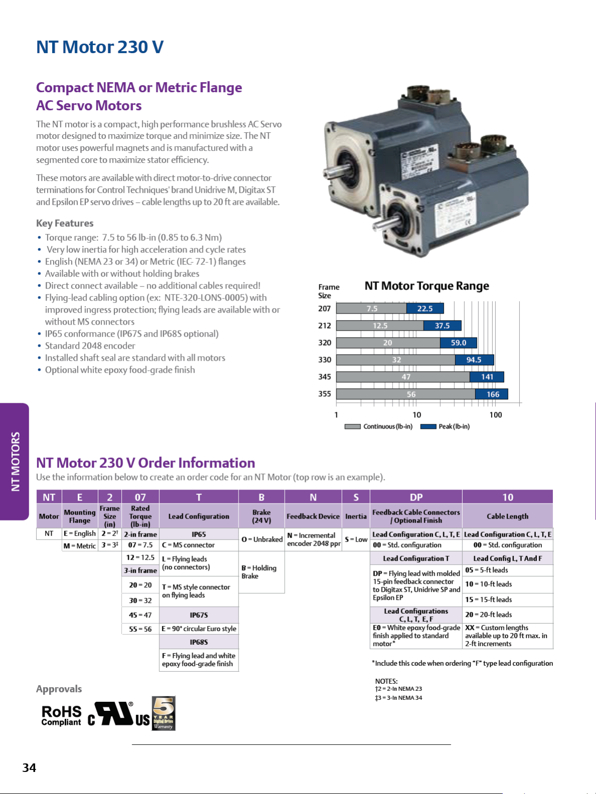
Frame
Size
207
212
320
330
345
;---
-'--::;;
l---~~
I---~~~
I---~~~~
NT
.:::l;.-
Motor
~~
.:;=;
c...,....,~~-
.;:,:;:
:,....,..~
:;:;..~-~~~
Torque Range
-~~
NT
Motor
Use
the information below
NT
Approvals
230
V Order Information
to
create an order code for an
Le,id
Configuriltion
2-in frame
12 = 12.5
J-in frame
20=20
30=
32
45=4
7
55=
56
+---------1
L =
(no connectors)
T =
on
E = 90' circular
f =
epoxy food-grade
IP65
MS
connector
Aying
leads
MS
style connector
flying
leads
IP6
IP68S
Aying
lead and white
7S
Euro
0
B=
Brake
style
finish
355 t===i==i::::::i:::::i::
c::::::::J
NT
Motor (top row
= Unbraked N = Incremental S =
encoder 2048 ppr
Holding
is
an example).
m~
=:::i::::=i=:::i::::i:
10 1
Contlnuous(lb-ln) - Peak(lb-ln)
Low
Lead Configuration C,
00
= Std. configuration 00 = Std. configuration 07 =7.5 C =
Lead Configuration T Lead Config
DP=
Aying
lead with molded OS = S-ft leads
15-pin feedback connector 1
to
Digitax ST,
Epsilon
EP
Lead
Configurations
C,
EO
finish
motor•
'lndu
NOTES:
f2 = 2-
p =
L,
= White epoxy food-grade
applied
de this code when ordering •p-type lead configuration
ln
NEMA
3-
ln
NEMA
Unidrive
T,
E, f
to
standard
23
34
L,
SP
T, E
Le,id
o = 10-ft leads
and
>----------<
1 S = 15-ft leads
20 = 20-ft leads
XX=
available up to
2-ft increments
~m~
00
Co1ble
Length
Configuration
Custom lengths
__j_
L.
20
C,
L, T, E
T And f
ft
max.
in
~~~
c'i\lus~
34

NT
Motor
Motor
Frame Size (in)
Voltage
Mo
Continuous Stall Torque (lb-in)
Continuous Stall Torque (Nm)
Cogging (lb-in) (typ.)
Cogging (Nm) (typ.)
.
-
-
NOTES:
•
.6.t=
212
'F
subject to.,.,_
• Stall torque, rated torque and power relate
operation above
• Maximum
(100 '
10%
intermittent
2-inch Frame Ratings and Dimensions
(Vrms)
del
Peak Torque (lb-in)
Peak
Torque (Nm)
Inertia (lb-in-sec')
Inertia (kgm') 0.0000106 0.0000185
Motor Weight (lbs)
Motor Weight (kg)
Kt
(lb-in/Al=
Kt(Nm
Ke
(V/k
rpm)=
Rated Torque (lb-in)
Rated Torque (Nm)
Stall Current
Rated Power
R (ph-ph) (Ohms)
L (ph-ph) (mH)
CJ
winding 104 ' F (40
tolerance
10
kHz drive switching frequency
winding
0.000094 0.000164
/AI
= 0.58 0.57
(A)
(kW)
'CJ
temperature
NT-207
7.5 12.5
0.85
22.5
2.54
0.094
0.011
3.0
1.36
5.12
35
7.50 12.50
0.85
1.7
0.432 0.740
11.1 4.56
39.1 18.9
maximum ambien
to
NT-212
1.4
37.5
4.24
0.12
0.014
4.0
1.81
5.08
34.7
1.4
2.7
maximum continuous
is
284
'F (140
t;
'CJ
all
data
I,
H
ue1so.stJ
,k45.21)
J_
__
l_
-
----
1---------
-
---
ENCOOER
MATIIG
CONN:
CONN:
BRAKE
MATIIG
~
-
------
,,
A
PT02Eo16-23P
PT(MjE-16-23S
CONN:
PT02E..g.JP
CONN:
MOTOR
MATING
(<ONSand<BNS)
PT(MjEo&-JS
CONN:
CONN:
1-•-
i
[
(-CSNS)
PT02Eo1&-8P
PTO&E-16-8S
>-K
I
- J
I
(<ONSand<BNS)
Motor
Dimensions
Unbraked length-CONS/EONS•
Braked Length -
Un
braked length-CBNS/EBNS •
length -TBNS/LBNS/FBNS
Braked
Bolt Circle Diameter
Connector Height -
Height-
Connector
Keyway
are
repres
NOTE:
• Not
Connector
Connector Height -
all
variations
English Flange
NTE-207 NTE-212
llllmlllllmllllllmllllllffl!D
5.55 141.0 6.55 166.4
TONS/LONS/FONS
Flange Square
Flange Thickness C 0.29 7.5 0.29 7.5
Pilot Diameter
Pilot Thickness
Bolt Hole Diameter
CONS
TONS/LONS
Height-
CBNS
TBNS/LBNS
Shaft Length
Shaft Diameter
length
(mini K 0.70 17.8 0.70 17.8
Keyway
Depth l 0.08 2.0 0.08 2.0
Keyway Width
ented
above; see
4.39 111.5 5.39 136.9
A
6.94 176.4 7.94 201.8
6.28 159.4 7.94 201.8
B 2.27 57.7 2.27 57.7
D 1.50 38.1 1.50 38.1
E 0.10 2.5 0.10 2.5
F 0.21 5.2 0.21 5.2
c;
2.63 66.7 2.63 66.7
1.92 48.9 1.92 48.9
1.78 45.2 1.78 45.2
H
1.98 50.4 1.98 50.4
1.78 45.2 1.78 45.2
I 1.21
0.37 9.5 0.37 9.5
I
M 0.13
our
website for complete mechanical dimension drawings
30.7
Shaft
3.2
Key
Dimen
1.21
sio
0.13
ns
30.7
3.2
I
Metric Flange
~
(in) (mm ) (in) (mm )
5.55 141.0 6.55 166.4
4.39 111.5 5.39 136.9
6.94 176.4 7.94 201.8
6.28 159.4 7.28 184.8
2.57 65.2 2.57 65.2
0.29 7.5 0.29 7.5
2.36 60.0 2.36 60.0
0.10 2.5 0.10 2.5
0.23
2.95 75.0 2.95 75.0
1.92
1.78
1.98
1.78 45.2 1.78 45.2
0.93 23.5 0.93 23.5
0.43 11.0 0.43 11.0
0.51 13.0 0.51 13.0
0.08 2.1 0.08 2.1
0.16
5.8
48.9
45.2
50.4
Shaft Key Dimensions
4.0
0.23
1.92
1.78
1.98
0.16
I
5.8
48.9
45.2
50.4
4.0
35
 Loading...