

Page 1

EF
Installation Guide
UD70
MD29
Second Processor Options
for Unidrive and Mentor II
Part Number: 0460-0098
Issue Number: 3
www.controltechniques.com
Page 2

Safety Information
The option c ard and its associated drive are intended as componentsfor professional
incorporationinto complete equipment or systems. If installed incorrectlythe drive may
present a safety hazard. The drive uses high voltages and currents,c arries a high level
of stored electricalenergy,and isused tocontrolmechanicalequipmentthat can cause
injury.
Close attention is required to the electrical installation and the system design to avoid
hazards either in normal operation or in the event of equipmentmalfunction. System
design,installation, commissioning and maintenancemust be carried out by personnel
whohave the necessary training and experience. They must read this safety information
and this InstallationGuide carefully.
Carefulconsideration must be given tothe functions ofthe drive and option c ard which
mightresultin a hazard, either through theirintendedfunctions, e.g. auto-start,or through
incorrectoperationdue toa faultor trip,e.g.stop/start,forward/reverse,m aximum speed,
loss of a communications link.
In any application where a malfunctionof the drive oroption card could lead todamage,
loss or injury, a riskanalysis mus t be carried out, and where necessary, further measures
taken to reduce t he risk.To ensuremechanical safety, additionalsafetydevicessuch as
electro-mechanical interlocks may be required. The Drive mustnot be used in a safetycritical application withoutadditionalhigh-integrity protectionagainsthazards arising
from a malfunction.
General Information
The manufacturer accepts no liability for any consequences resultingfrominappropriate,
negligent or incorrectinstallation or adjustment of the optional operating parameters of
the equipment or from mismatching the Drive with the motor.
ThecontentsofthisUserGuidearebelievedtobecorrectatthetimeofprinting. Inthe
interests of a commitment toa policyof continuous development and improvement, the
manufacturer reserves the rightto change the specification of the productor its
performance, or the contents ofthe U ser Guide, without notice.
Allrightsreserved. No part of this U ser Guidemay be reproduced or transmitted in any
form or by any means, electrical or mechanicalincludingphotocopying, recording or by
any informationstorage or retrieval system, without permission in writingfrom the
publisher.
Copyright © 25/1/02ControlTechniquesDrives Ltd
IssueCode: 3
Hardware: UD70 All Issues, MD29 Issue 3 and later
Firmware: N/A
Page 3

Contents
1 Mechanical Installation 1
1.1 Unidrive and UD70 1
1.2 MentorII and MD29/MD29AN 3
2 Electrical Installation 5
2.1 UD70 5
2.2 MD29 5
2.3 MD29AN 6
2.4 RS232Port Connections 6
2.5 RS485Port Connections 6
2.6 I/O Box Port Connections(MD29 Only) 8
2.7 Digital I/O Connections 8
3 RS485 Port Configuration 9
3.1 Node Address 9
3.2 Data Rate 10
3.3 RS485 Port CommunicationsModes 10
3.4 Storing configuration parameters 12
UD70/MD29 Installation Guide
Issue Number: 3 www.controltechniques.com
Page 4

1 Mechanical Installation
NOTE
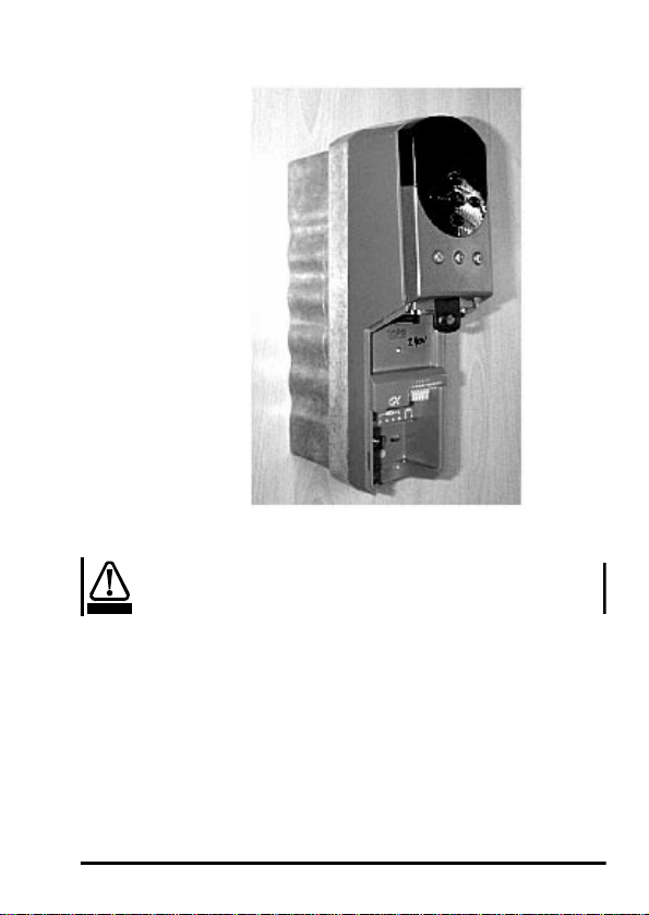
1.1 Unidrive and UD70
Before attempting to installoption modules or cards, e nsure that the U nidrive
or Me ntor II is switched off. AC Drives should be left for 5 minutes to ensure
that the DC link capacitorshave completely discharged.
• Slidethe UD70 moduleunder the displaypanelof theUnidrive,and push the
modulein untilthe connector locates withthe plug insidethe Unidrive.
1 UD70/MD29 Installation Guide
www.controltechniques.com Issue Number: 3
Page 5
WARNING
• Applyfirm pressure, andthe module will click securely into place.
• To remove the UD70, pullfirmly on the black tab,and the module will
disengagefrom the connector.
Do not attempt to remove the UD70 modulewhile the Unidrive is still powered
up, as this may caus e damage to the Unidrive.
UD70/MD29 Installation Guide 2
Issue Number: 3 www.controltechniques.com
Page 6

1.2 Mentor II and MD29/MD29AN
The MD29 is fitted ontothe 40-way pin header (PL1)on theMDA2B circuit board.
The supplied mounting pillars should beattached to the MDA2B on the Mentor II.
• Tilt the MD29at an angle and locate thefirstfew pins into theMD29 header.
3 UD70/MD29 Installation Guide
www.controltechniques.com Issue Number: 3
Page 7

• Tiltthe boardto horizontal to engage the restof thepins. Pressfirmly
downwardsto firmly fix the MD29to the header and 4 mounting pillars.
NOTE
WARNING
UD70/MD29 Installation Guide 4
Issue Number: 3 www.controltechniques.com
Take care when locating the board onto this connector - do not force it on.
Excessiveforce may bend and break the pins of the header.
When removing an MD29, unsnap the MD29 from the pillars before gently w orking
the MD29 off the header. Do nottilt the MD29 excessively to one side, as this may
bend and breakthe end groups of pins on the header.
Do not attempt to remove the MD2 9 while the Mentor II is stillpowered up,as
this may cause damage to the Mentor I I.
Page 8

2 Electrical Installation
2.1 UD70
The UD70 providesa dedicated RS232programming port (Connector C) and a
general purpose RS485 communications port (Connector D )..
Connectors A and B provide t he connectors for high speed fieldbus communication
options,if fitted. Refer to theappropriate fieldbus option User Guide for full fieldbus
connection details.
2.2 MD29
The MD29 providesa dedicated RS232programmingport (Connector SK2) and a
general purpose RS485 communications port (Connector PL1). In addition, the
MD29 also has a dedicated RS485 port(Connector TB1) for use with theControl
TechniquesI/O Box.
SK2
AB
DC
SW1
MD29
15
PL1 SK2TB1
5 UD70/MD29 Installation Guide
www.controltechniques.com Issue Number: 3
Page 9

2.3 MD29AN
The MD29AN provides a dedicated RS232 programming port (Connector SK2) and
a general purpose RS485 communications port (C onnector PL1). In addition, the
MD29 also has a dedicatedCTNet port(PL2).
SK1
MD29AN
PL1 SK2PL2
2.4 RS232 Port C onnections
The pin connections for theRS232 portare givenin the table below. The R S232
portcan beconnectedto a 9 wayserialport using a 9-way one-to-oneribbon cable
lead.
Pin Function Description
2 TxD Transmit line
3 RxD Receive line
50V0V
2.5 RS485 Port C onnections
The pin connections for theRS485 portare givenin the table below 0VSC is
completely isolated from the main Unidrive and Mentor II 0V.
Pin Function Description
1 0VSC 0VSC Isolated0V forserial communicationslink.
2 TxA /Tx Inverted transmit line
3 RxA /Rx Inverted transmit line
6 TxB Tx Transmit line
7 RxB Rx Rec eive line
UD70/MD29 Installation Guide 6
Issue Number: 3 www.controltechniques.com
Page 10

2.5.1 4 Wire RS485 Network
The diagram belowshows the connections required for a 4 wire RS485network,
usinga mastercontrollerwith an RS485 port. The UD70 and MD29 can be
configured to act as master controllers,but thisrequiresDPL programming to
controlthe network.
Master
0V
TxB
TxA
RxB
RxA
120Ω 0.25W
termin atio n resisto rs
An RS232-to-RS485 converter is required to allow a standardPC serial port to
2.5.2 2 Wire RS485 Network
communicatewitha4wireRS485network.
The diagram belowshows the connections required for a 2 wire RS485network,
usinga mastercontrollerwith an RS485 port. The UD70 and MD29 can be
configured to act as master controllers,but thisrequiresDPL programming to
controlthe network.
Master
0V
TxB
TxA
RxB
120Ω 0.25W
RxA
termination resistor
An RS232-to-RS485 converter with “intelligent transceiver switching”(also known
as “magic” RS485converters)is required to allowa standard PC serial portto
communicatewitha2wireRS485network. Anexampleofa“magic”converteris
the MA485F converter from Amplicon.
NOTE
A “magic” converter is not requiredis the master c ontoller has a n RTScontrol
output. Thisoutput is enabled w hen the master is transmitting,and disabled
when the master is not transmitting. Control Techniques software packages
(UniSoft, MentorSoft and SystemWise) do NOT switch the RTS line.
Slave
UD70, MD29,
Unidrive,M entor II
12637 12637
RxARxBTxATxB0V RxARxBTxATxB0V
Slave
UD70, MD29,
Unidrive
12637 3 7 2
Slave
UD70, MD29,
Unidrive,M entor II
Slave
Commander SE
TxRxA0V
TxRxBRxARxBTxATxB0V
7 UD70/MD29 Installation Guide
www.controltechniques.com Issue Number: 3
Page 11

2.6 I/O Box PortConnections (MD29 Only)
The I/O Box port is marked “PL2”and is only availableon the MD29. The terminal
connections are shown in the table below. Operation of this port is automatic, and
no configuration is necessary.
Pin Function Description
10V0V0V
2 TxB Tx Transmit line
3 /TxA /Tx Inverted Transmit line
4 RxB Rx Receive line
5 /RxA /Rx Inverted Receive line
NOTE
To us e the I/O Box with UD70 or MD29AN, connect it to the R S485 port, and
select Mode 10 communications.
2.7 Digital I/O Connections
The RS485 connector has 2 TTL digitalinputs and 1 TTLdigitaloutput.They are
used in conjunction with the Timer/Counter unit. (Forfurtherdetails,refer to the
Userguide forthe UD70 or MD29.)
NOTE
NOTE
The0VSC isisolatedfrom the U nidrive or Me ntor II0V, and shouldnotbe used
as the reference 0V for the TTL digital inputs and output.
If a digitalinput is open-circ uit or connected to +5V, this willbe readby #86.01
(input 0) or #86.02(input 1) as logic 0. These parameters will change to logic 1
when the inputs are connectedto 0V Digital on pin 9.
The digitaloutput will give +5V when #86.03 isset tologic 0, and 0Vwhen setto
logic1. Thedigitaloutput is rated to a maximum of 15mA. The maximum lengthof
cablethatshould be connected to theseterminalsis 0.5 metres, so buffering will be
required forlonger lengths of cable,and for interfacingto different logic levels.
The Digitalinputs a nd output must be connected to 0V Digital (pin 9), NOT
OVSC (pin 1). The inputs and output will not work properly if connected to
OVSC, as pin 1 is isolated fromthe Drive. Noise generatedalong the screen
of theserial communications cable may cause spurious operation, and
damagetotheUD70orMD29mayresult.
UD70/MD29 Installation Guide 8
Issue Number: 3 www.controltechniques.com
Page 12

3 RS485 Port Configuration
TheRS485portcanbeusedtocommunicatewiththeDriveusingControl
Techniques' standard software communications packages such as UniSoft,
MentorSoft, CTFile and Systemwis e. (Refer to the Help file in Unisoft, MentorSo ft,
etc. f or connection details.) The ANSIprotocolis the standard protocol used bythe
ControlTechniques'softwarepackages,but Modbus RTU and ASCII modes are
alsosupported as slave nodes only.
The RS485 portis configured by settingcertainuser parameters on theUnidriveor
MentorII. These control individualfeaturesabout the port.Any changes take effect
when the configurat ion parameters are storedand t he UD70 or MD29 isreset.
The following parameters used to configure the RS485 port.
Function Unidrive
Node Address #17.05 #14.01
Data Rate #17.07 #14.03
SerialComms Mode #17.06 #14.02
Pointer1 #17.08 #11.09
Pointer2 #17.09 #11.10
ScalingFactor #17.10 #11.11
Global Trip Enable #17.14 #14.07
RS485 Trip E nable #17.15 #14.08
3.1 Node Address
Unidrive: #17.05 Mentor I I: #14.01
Range: 11 to 99, excluding 00 to 09, 10, 20, 30, 40, etc for ANSI.
Default: 11
Every node on an ANSI or Modbus network MU ST be assigned a unique serial
address. Changes to the node address will not take effect until theparameters
have been stored, and the U D70 or MD29 has been reset.
The serial address ensures that only the intendednode responds to commands
issuedby thenetwork master control ler. Eachnode should be assigned a unique
addressBEFORE itis connected to the RS485 network.
1 to 99 forModbus RTUand ModbusASCII
(UD70)
Mentor II
(MD29/MD29AN)
9 UD70/MD29 Installation Guide
www.controltechniques.com Issue Number: 3
Page 13

3.2 Data Rate
Unidrive: #17.07 Mentor II: #14.03
Range: 300 t o 38400 bits per second
Default: 4800
Every node on an ANSI or Modbus network must be configured to operateat the
samedata rate. Setthe appropraite value as shownin thetablebelow to configure
the RS485 portdata rate.
Data Rate
(bits/sec)
300 300 3
600 600 6
1200 1200 12
2400 2400 24
4800 4800 48
9600 9600 96
19200 19200 192
38400 38400 38
Unidrive Me ntor II
3.3 RS485 Port C ommunications Modes
Unidrive: #17.06 Mentor II: #14.02
The serial communications mode selector determines the mode of operation of the
RS485 serial port, and the protocol supported. Only slavemodes are described
3.3.1 Standard CT ANSI Protocol
3.3.2 Modbus RTU
here. (Modes 6 to 9,11 and 12 require DPL code to control the RS485.)
Mode 1 - 4 Wire ANSI Slave Mode (Default)
Mode 5 - 2 Wire ANSI Slave Mode
The UD70 and MD29 will communicate using the Control Techniques' standard
ANSIprotocolwith a 4-wireor 2-wire connection. This mode allowstheUnidriveor
MentorII t o communicatewith standard CT software packages,such asUniSoft,
MentorSoft, SystemWise, etc.
Menu 0 parametersare notaccessiblethrougha UD70 or MD29. Referto the
User's Guide for MD29 or UD70 for a deta iled description of the ANSI protocol.
Mode 13 - 4 WireModbus RTU Slave Mode
Mode 15 - 2 WireModbus RTU Slave Mode
The UD70 and MD29 will communicate using the Modicon ModbusRTU protocol
witha 4-wireor 2-wire connection. Thedata frame usedfor Modbus RTU is 1 start
bit, 8 databits, no parity, 2 stopbits. (Evenparitywith 1 stop bitis NOT currently
supported. )
The following MOdbus RTU commands aresupported:
FC3 PRESET SINGLE REGISTER
FC6 PRESET MULTIPLE R EGISTERS
FC16 READ MULTIPLE REGISTERS
The maximum numberof registers that c an be transferred on a s ingle message is
limited to 20, and the range of allowed node addresses is limited from 1 to 99.
UD70/MD29 Installation Guide 10
Issue Number: 3 www.controltechniques.com
Page 14

3.3.3 Modbus ASCII
Mode 14 - 4 WireModbus ASCIISlave Mode
Mode 16 - 2 WireModbus ASCIISlave Mode
The UD70 and MD 29 will communicate using theModicon Modbus ASCII protocol
with a 4-wireor 2-wire connection. The dataframe used forModbus RTU is 1 start
bit,7 databits, no parity, 2 stop bits.
The following Modbus ASCIIcommands are supported:
FC3 PRESET SINGLE REGISTER
FC6 PRESET MULTIPLE R EGISTERS
FC16 READ MULTIPLE REGISTERS
The maximum numberof registers that can be transferred on a single message is
limited to 20, and the range of allowed node addresses is limited from 1 to 99.
3.3.4 Master/Slave
Mode 2 - Master Mode
Mode 3 - Slave Mode
In Mode 2, the node acts as a master,and continuously broadcastsa source
parameter,as definedby thePointer parameter, from the RS485 port at a f ixed
datarate of 9600 bits/sec.The valueof thesource parameter is scaledto ±16000.
In Mode 3, the node acts as a slave to receivethe continuous data stream
transmittedbyaMode2master.Theincomingdataismultipliedbythescaling
parameter,and written to the destination parameter,as defined bythe Pointer
parameter.
Master Node (Mode 2) Slave Node (Mode 3)
Pointer1
Pointer1
Unidriveor
Mentor II
parameters
Ifthe serial communicationslinkis broken, t he slavenodecan bemade to trip. This
is done by setting the Global Trip Enable and RS485 Trip Enableparameters.
11 UD70/MD29 Installation Guide
Scaleto+/-
16000
RS485 port
37162
Scaling
parameter
RS485 port
37162
www.controltechniques.com Issue Number: 3
Unidrive or
Mentor II
parameters
Page 15

3.3.5 Cascade
Mode 4 - Cascade Mode
Mode 4 providesallows UD70 and/orMD29 RS485 ports tobe “cascaded”. This
mode is similar to the Master/Slavemode, except thateach node can be a slave to
an “upstream” node, AND a master to a “downstream” node.
Pointer 1
Scaling
parameter
Receive data from
previous node
3.3.6 I/O Box Mode (UD70 and MD29AN only)
Mode 10 - I/O BoxMode
Unlike the MD29, the U D70 andMD29AN do not have a dedicatedport for usewith
the I/O Box. Thegeneral purpose RS485 port can be configured to communicate
directly with an I/O Box by configuring the RS485 port to use Mode 10
communications.
Unidrive or
Mentor II
parameters
RS485 port
37162
3.4 Storing configuration parameters
In all cases,the configuration parameters must be stored,and the UD70or MD29
3.4.1 Unidrive
3.4.2 Mentor II
resetbefore changes w ill take effect.
• To store c hanges inmenu 17parameters, set #MM.00to 1000and press the
red RESET button.
• To reset theUD70, set#MM.00 t o 1070 and press the red RESET button.
• Ensure that the Mentor II is disabed
• To store c hanges inmenu 11and 14parameters,set #MM.00 to1 and press
RESET. This will also reset the MD29.
Pointer 2
Scale to +/-
16000
Transmit data to
next node
1
UD70/MD29 Installation Guide 12
Issue Number: 3 www.controltechniques.com
 Loading...