

Page 1
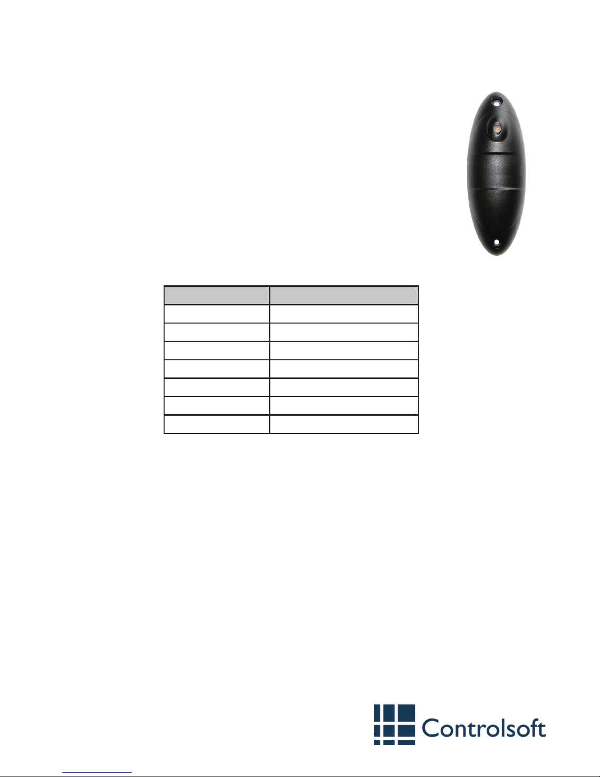
Mullion Proximity Reader
Part Codes: CS-AC-1200-BK
CS-AC-1200-WH
www.controlsoft.com
Introduction
The CS-AC-1200 proximity reader from Controlsoft® reads Controlsoft
125KHz cards and tags, and connects to any Access Control Unit (ACU) via
a Wiegand interface.
The reader is available in black (-BK) or white (-WH) and has an internal
piezo buzzer and tri-colour LED to indicate status.
The circuitry is encased in a durable, waterproof resin, making it suitable
for indoor and outdoor use.
Step 1 — Mount the Reader
Use the template provided to mark and drill the 3 required holes. Plug the
mounting holes (if required), feed the pigtail through the cable entry hole
and mount the reader.
9010-0020 Issue 3
Step 2 — Connect the Reader to the ACU
The reader is supplied with a 1 metre ‘pigtail’ lead with the following connections:
Colour Signal Description
Red Power Supply (+12Vdc)
Black Ground (0V)
Green Data 0
White Data 1
Purple Green LED Control
Yellow Buzzer Control
Brown Red LED Control
Connect the reader as described in the Installation Instructions for the ACU. Information on
wiring to a Controlsoft i-Net™, Reader Expander Board, Edge or Solo 2 is provided overleaf.
If the length of the pigtail needs to be extended, it is important to use screened, non twisted
cable such as Belden 9538 which must not exceed 100 metres.
If the distance between the ACU and reader is more than 25 metres, power must be supplied
to the reader by a power supply mounted close to the reader.
Step 3 — Test the Reader
To ensure correct operation of the reader, test the connections to the ACU by referring to the
following checklist:
1. The LED is ashing green (normal wait state).
2. An allowed card swiped at the reader generates a beep and the LED to turn green
(normal allow state).
3. A denied card swiped at the reader generates a long beep and the LED to turn red
(normal deny state)
4. If the reader does not respond when a card is presented, the card is not enrolled at the
ACU (normal deny state) or some form of interference may be present.
5. A yellow LED, or the buzzer remains permanently on indicates that the reader is
experiencing operational problems. Check that the connections are correct, and that the
reader has adequate power.
Installation Instructions
Page 2
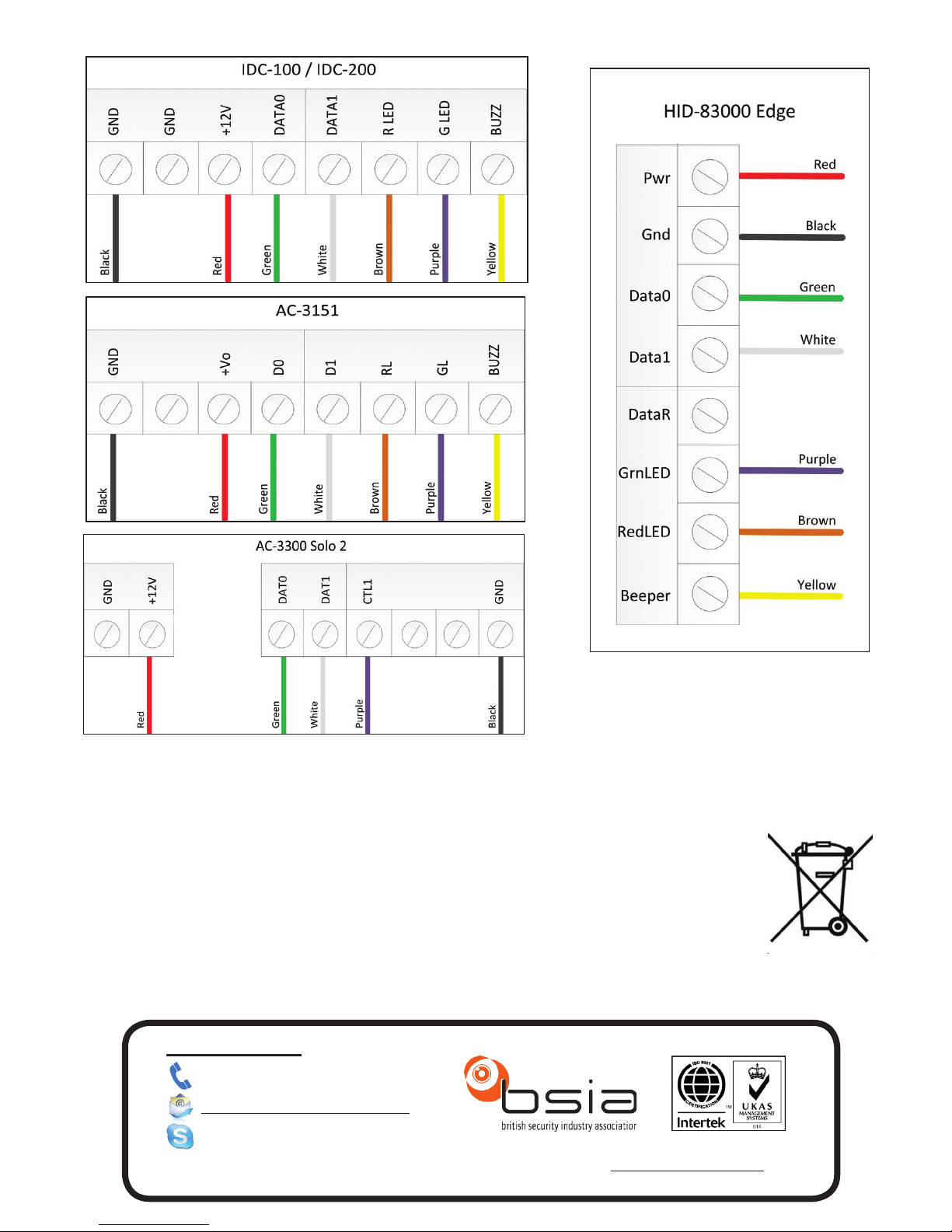
CS-AC-1200 - Wiring Diagram
Caution:
The “crossed out wheeled bin” logo on Controlsoft products indicates that this product should
not be disposed of via the normal household waste stream.
To prevent possible harm to the environment or human health, please separate
this product from other waste streams. For further information, contact your local
government ofce or the retailer where you purchased product.
This information only applies to customers in European Union.
For other countries, please contact your local government to investigate the
possibility of recycling your product.
Controlsoft UK
+44 (0)1451 844896
controlsoft.uk.support
Information on all our products can be found on our website www.controlsoft.com
 Loading...