

Page 1
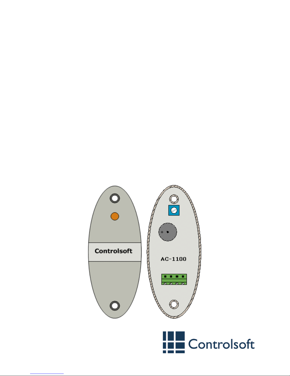
RS485 Proximity Reader
Part Codes: CS-AC-1100-BK
CS-AC-1100-WH
Introduction
The CS-AC-1100 is a proximity reader for Controlsoft® 125kHz proximity cards and
tags and is available in black (-BK) or white (-WH). A piezo buzzer and a tri-colour
LED indicate reader status to make the device very easy to use.
The reader circuitry is encased in a durable, waterproof resin, making it suitable for
both internal and external use.
Step 1: Prepare the installation
The reader can be mounted against any surface and in any orientation. A template
is provided to mark the position of the required holes. Drill the holes, plug the
mounting holes (if required) and feed the cable through the cable entry hole.
www.controlsoft.com
9010-0012 Issue 2
Installation Instructions
Page 2
Step 2: Set the RS485 Address
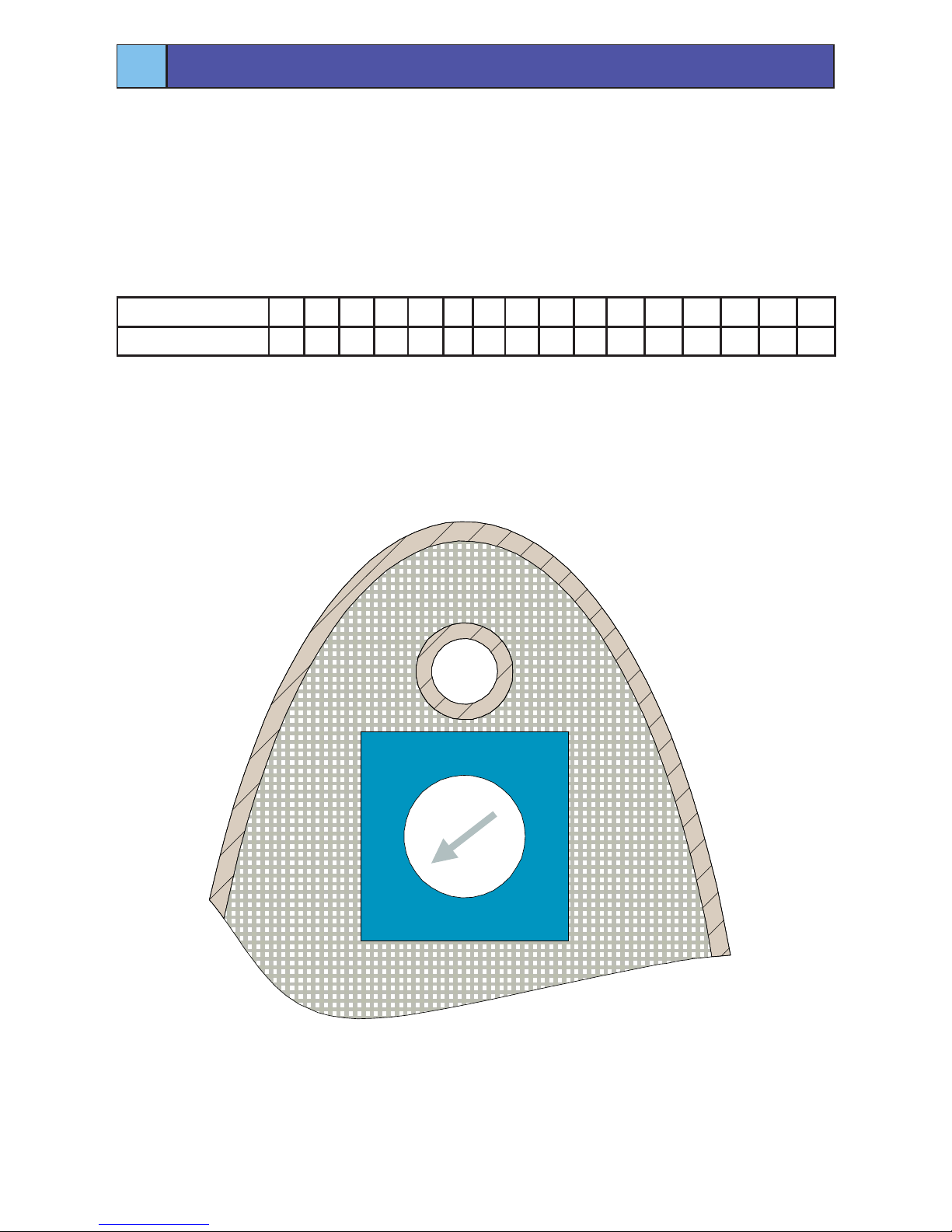
The reader communicates with the i-Net™ ACU via an RS485 bus. Each device on
the RS485 bus must be assigned with a unique address. The RS485 bus supports up
to 16 devices, so the reader has a 16 position rotary switch marked ‘0’ to ‘F’.
The table below shows how the switch position relates to the address:
2
Set the RS485 Address
Rotary Switch 0 1 2 3 4 5 6 7 8 9 A B C D E F
RS485 Address 0 1 2 3 4 5 6 7 8 9 10 11 12 13 14 15
For further information on RS485 Bus Addressing, please refer to the i-Net
Installation Instructions.
Always keep a record of the address used to avoid duplication.
C
B
A
9
8
6
5
4
3
2
1
7
0 F
E
D
AC-1100
Page 3
Step 3: Connect the RS485 Bus
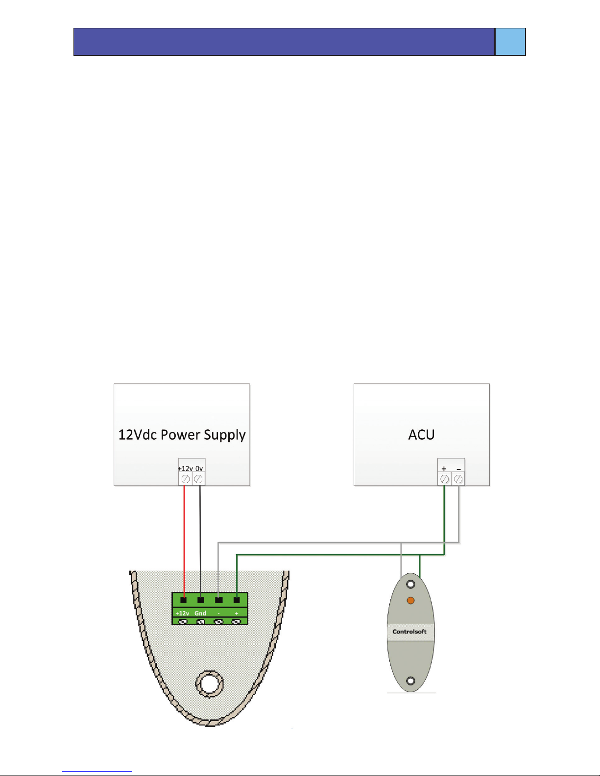
Connect the reader to the RS485 bus as shown in the diagram below. The maximum
length of the RS485 bus is 1000 metres end to end.
For RS485 connections we recommend using Belden 8723 or equivalent. This is a 2
twisted pair cable, with each pair screened as well as an overall screen. It is possible
to use screened CAT5 or screened CAT6 but we recommend using stranded cores as
opposed to solid cores.
Note: the RS485 ‘+’ and ‘–’ connections must be run on either side of the same
twisted pair (e.g. Green and White).
If the reader is at the end of the RS485 bus, then a network termination resistor (120
ohms) must be tted between the RS485 ‘+’ and ‘-’ connection at the reader terminal
blocks.
Step 4: Connect Power
The reader requires 12Vdc power at 100 mA for normal operation.
Whenever power is rst supplied to the reader, the piezo buzzer sounds and the LED
ashes yellow for approximately 2 seconds.
3
Connect the Reader
Page 4
4
Test the Reader
Caution:
The “crossed out wheeled bin” logo on Controlsoft products indicates that this product
should not be disposed of via the normal household waste stream.
To prevent possible harm to the environment or human health, please
separate this product from other waste streams. For further information,
contact your local government ofce or the retailer where you purchased
product.
This information only applies to customers in European Union.
For other countries, please contact your local government to investigate
the possibility of recycling your product.
Controlsoft UK
+44 (0)1451 844896
controlsoft.uk.support
Information on all our products can be found on our website www.controlsoft.com
Step 5: Mount the Reader
Mount the reader using the screws supplied. To provide additional protection to the
terminal blocks and rotary switch, we recommend that you seal around the reader
using a mastic or similar sealant.
Step 6: Test
To ensure that the reader is operating correctly, check that:
1. The LED is ashing green (normal wait state).
2. An ‘allowed card’ swiped at the reader causes a double beep and a solid green
LED for approximately 3 seconds (allow state).
3. A ‘denied card’ swiped at the reader causes a double beep and a solid red LED
for approximately 3 seconds (deny state).
• If the LED ashes orange, there is a communication problem to the ACU. Check
that the ACU is operating normally, that the reader is connected to the ACU and
the power supply, and that the RS485 address is unique.
• If the LED and/or buzzer remain on permanently, the reader is experiencing
operational problems. Check that the reader has adequate power and that it is
correctly connected to the ACU.
 Loading...