

Page 1
4
Specications
LED Indications
Start-up Mode:
Flashing Red - Pulse Relay, waiting for rst ‘Master’ Card
Flashing Orange and Green - Latch Relay, waiting for rst ‘Master’ Card
Programming Mode:
Solid Orange - Programming mode, waiting to add/remove users
Green - User added
Red - User removed
Standard Operating Mode (3 Second Pulse)
Red - Normal operation, waiting for card/tag
Green + buzzer - Valid card/tag presented
Red + buzzer - Invalid user
Standard Operating Mode (Latch)
Valid user - LED alternates between Green and Red and
buzzer will sound
Invalid user - LED remains Green or Red and buzzer sounds
Technical Specications
Input Power Supply 12V DC
Average Current Consumption 30mA
Relay Rating 5A @ 250V AC
Operating Frequency 125 KHz
Indications Read Range
Visual - Tri-Colour LED ISO Card - 70mm
Audible - Buzzer Tags - 50mm
Mechanical
Packaging Formats: ABS blend, UV resistant
Stainless Steel / Vandal resistant
Industry Standard Panel Mount (40mm x 40mm)
Operating Temperature -10°C to +60°C
Protection Category IP67 (Submersible)
Note: The Relay has a rating of 5A @250V AC maximum.
If switching a load with a higher current rating, use an external relay with the necessary current rating. ALWAYS t a MOV across the coil of this interface relay.
Installation Instructions
www.controlsoft.com
Introduction
The AC-3100, AC-3101 and AC-3102 from Controlsoft® are standalone “All-in-One”
controllers with integral reader, supporting up to 30 users. The 3 versions operate
exactly the same way, the only difference being how they are housed.
The 3 colour LED indicates the door status making the All-in-One very easy to use.
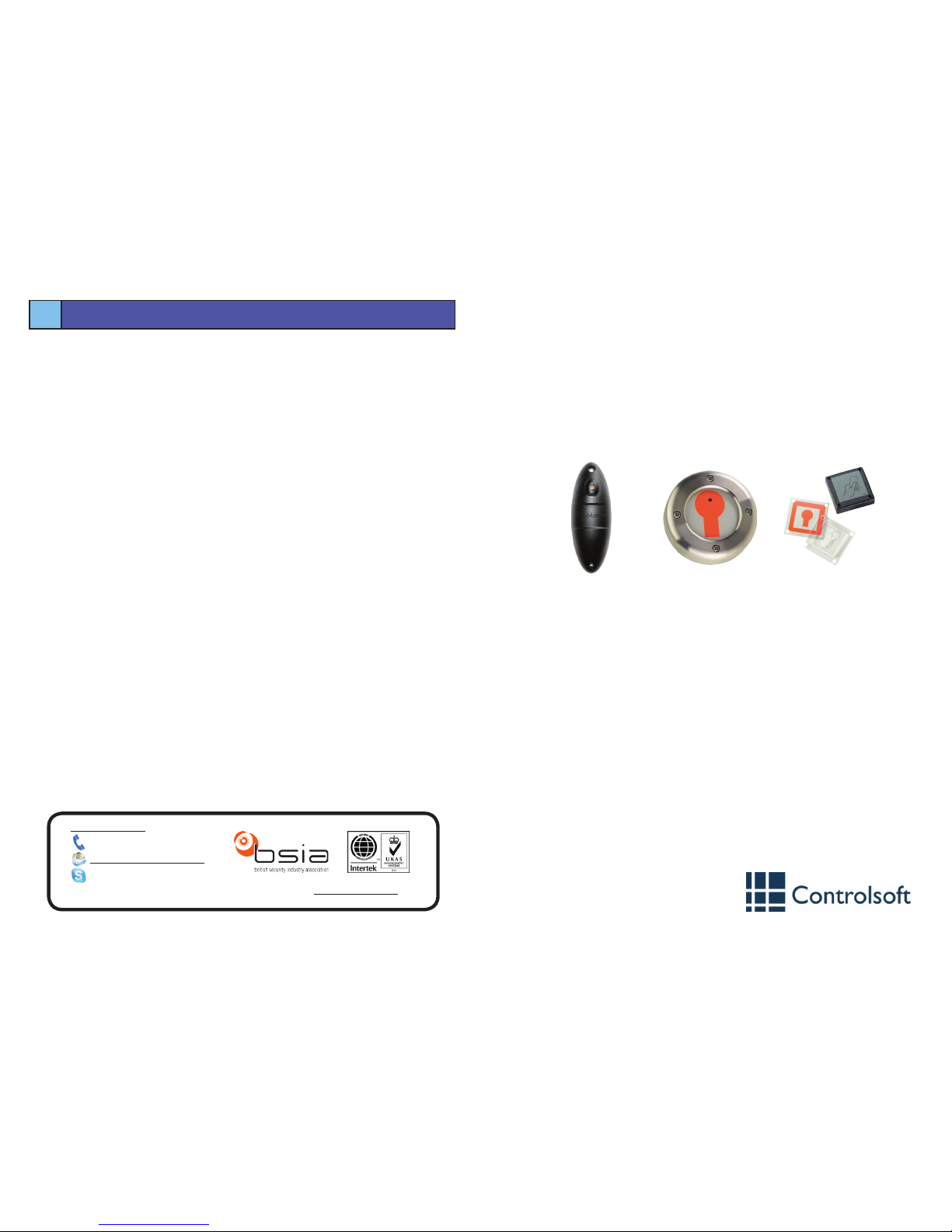
AC-3102
AC-3101
AC-3100
Step 1 — Mounting the All-in-One
• AC-3100: Use the Mounting Template provided to mark the 3 required holes.
• AC-3101: Remove the 4 security screws and separate the cover from the base. Use the
base as a template to mark the required holes.
Drill and plug the wall.
Push the cable from the All-in-One through the centre hole and secure the All-in-One to
the wall.
Important notes before you continue
• The All-in-One operates on 12V DC only.
• If the latch option is selected and the reader is connected to an electric strike lock,
the coil of the strike lock is likely to burn out.
• Before adding cards/tags to the All-in-One it must be in the chosen relay operating
mode. (Latch or Pulse)
Mullion
Vandal
Resistant
Panel
Mount
9010-0004 Iss 2
All in One
Part Codes: CS-AC-3100
CS-AC-3101
CS-AC-3102
Controlsoft UK
+44 (0)1451 844896
controlsoft.uk.support
Information on all our products can be found on our website www.controlsoft.com
Page 2
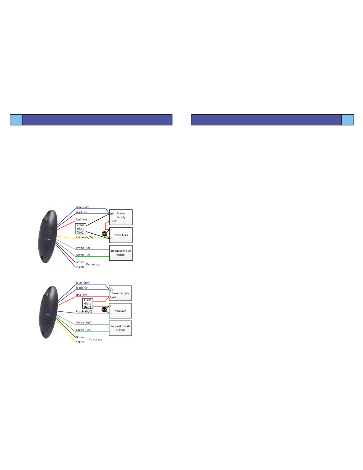
Step 2 — Identifying cable colours and their designation
The All-in-One is supplied with a pigtail cable.
There are eight (8) wires, and their colour / designation is listed below
Black - Ground (GND) - Power
Red - 12V DC - Power
White - RTE - Request to Exit Button
Green - RTE - Request to Exit Button
Yellow - Normally open relay contact - Door Strike Lock
Blue - Common relay contact - 0V / GND
Purple - Normally closed relay contact - Door Lock
Brown - Not used
The Request to Exit button must be normally open, going closed.
For Strike Locks, use normally open breakglass contacts (B & C on Controlsoft breakglass)
For Mag Locks, use normally closed breakglass contacts (A & C on Controlsoft breakglass)
3
Using the All-in-One
2
Wiring the All-in-One
For Failsafe Locks: i.e. Magnetic Locks
For Failsecure Locks: i.e. Strike Locks
Step 3 — Powering up the All-in-One for the rst time
When powering up the All-in-One for the rst time, the relay function must be dened rst.
The All-in-One LED will FLASH RED to signify Relay PULSE mode. Press the REX (or short
the Green and White wires) again, the LED will change to FLASHING GREEN AND ORANGE
to signify Relay LATCH mode.
When the required Relay mode is displayed, present the ‘MASTER’ card to the All-inOne which will respond with a double beep to indicate that the ‘MASTER’ card has been
accepted.
Step 4 — Testing the All-in-One operation
Present the ’MASTER’ card to the All-in-One and the buzzer will emit a short beep and the
door will unlock for 3 seconds (PULSE mode) or indenitely (LATCHED mode).
NOTE: To lock the door in LATCHED mode, simply present the ’MASTER’ card again
Step 5 — Adding and Removing Cards / Tags
NOTE: The rst card/tag after the ‘MASTER’ card has been added, will also be a ’MASTER’
card.
Present and hold the ’MASTER’ card to the All-in-One until it beeps twice and the LED
changes to ORANGE, indicating the device is in programming mode.
Remove the ’MASTER’ card and present cards/tags one at a time, the All-in-One will beep
once for each card. If the card is new, it will be added and the LED will show green. If the
card has been previously added, it will be removed and the LED will show red.
Once completed, present and hold the ’MASTER’ card to the All-in-One to exit programming
mode or wait 30 seconds and normal operation will automatically be selected.
NOTE: Presenting a card/tag twice to the reader while in programming mode will add, then
remove the card/tag from the database
Resetting the All-in-One
To reset the All-in-One press and hold the REX button (or short the Green and White
wires).
Disconnect the All-in-One from the Power Supply to power it off. Next power the All-inOne on, then off, then on again (approximately 1/2 second each). When powering up
for the second time the All-in-One will respond with a multiple beep, indicating that the
conguration is at factory defaults.
Release the REX (or remove the short from the Green and White wires) and proceed to
Step 3.
NOTE: When disconnecting power from the All-in-One, remove the connection from the
power supply as this generates a faster edge than switching the power supply on and off.
To prevent
back-EMF
damaging the
All-in-One,
always t a
MOV across
the terminals
of the lock
 Loading...