


Frame Rela
y
Digital Service Unit
User’s
Manual - Installation Guide
Pub. No. 980-001-0210G
June 1999
The information in this manual pertains
to Base Software Revision 07.01.XX
A P-COM Company


TRADEMARKS
Control Resources and NetPath are trademarks of Control Resources Corporation.
All other products, systems, or services mentioned in this document are trademarks,
service marks, registered trademarks or registered service marks of their respective
owners.
COPYRIGHT NOTICE
Copyright © 1996-199 9 Control Reso urces Corporatio n, a P-COM Company. A ll
rights reserved.
This publication is protected by federal copyright law. This publication contains
information proprietary and confidential to Control Resources Cor por ation. No part
of this publication may be copied or distributed, transmitted, transcribed, stor ed in a
retrieval system, or translated into any human or computer language in any form or
by any means, electronic, mechanical, magnetic, manual or otherwise, or disclosed
to third parties without the express written permission of Control Resources
Corporation, 16-00 Pollitt Drive, Fair Lawn, New Jersey, 07410.
Telephone (201) 703-4800, FAX (201) 703-4889.
Control Resources Corporation makes no representation or warranties with
respect to the contents hereof and specifically disclaims any implied warran ties
of merchantability or fitness for a particular purpose. Further, Control Resources
Corporation reserves the right to make product chan ges, to revis e this publicat ion
and to make changes from time to time in the contents hereof without obligation
of Control Resources Corporation to make changes in existing products or to
notify any person of such revision or changes.
EQUIPMENT INTERFERENCE NOTICE
This equipment has been tested and found to comply with the limits for a Class A
digital device pursuant to Part 15 of FCC Rules. These limits are designed to
provide reasonable protection against harmful interference when this equipment
is operated in a commercial environment. This equipment generates, uses, and
can radiate radio frequency energy and, if not installed and used in accordance
with the instruction manual, may cause harmful interference to radio
communications. Operation of this equipment in a residential area is likely to
cause harmful interference, in which case the user will be required to correct the
interference at his/her own expense.
This Class A digital apparatus meets all requirements of the Canadian
Interference-Causing Equipment Regulations.
Cet appareil numérique de la classe A respecte toutes les exigences du Règlement
sur le matériel brouilleur du Canada.

IMPORTANT SAFETY INSTRUCTIONS
When using your NetPath 100 equipment, basic safety precautions should always be followed to
reduce the risk of fire, electric shock and injury to persons, including the following:
1. Read and understand all instructions.
2. Follow all warnings and instructions marked on the product.
3. Unplug this product from t he wall o utlet befo re cleanin g. Do not use liq uid cleaners or aeros ol
cleaners. Use a damp cloth for cleaning.
4. Do not use this product near water, for example, near any sink or tub, or whe re the floor is wet.
5. Do not place this product on an unstable cart, stand or table. The product may fall, causing
serious damage to the product.
6. Slots and openings in the cabinet and the back or bottom are provided for ventilation, to
protect it from overheating; these openings must not be blocked or covered. The openings
should never be blocked by placing the product on a carpeted or other similar soft surface.
This product should never be placed near or over a radiator or heat register. This product
should not be placed in a built-in installation unless proper ventilation is prov id e d.
7. This product should be operated on ly from the type of powe r so urce indi cated on the marking
label.
8. Do not allow anything to rest on the power cord. Do not locate this product where the cord will
be abused by persons walking on it.
9. Do not overload wall outlets and extens ion cord s as this can r e sult in the risk of fire or electric
shock.
10. Never push objects of any kind into this product through cabinet slots, as they may touch
dangerous voltage points or short out parts that could result in a risk of fire or electric shock.
Never spill liquid of any kind on the pr oduct.
11. To reduce the risk of electric shock, do not disassemble this product, but contact Control
Resources Corporation if repair or warranty work is required. Opening or removing covers
may expose you to dangerous voltages or other risks. Incorrect reassembly can cause electric
shock when the appliance is subsequently used.
12. Unplug this product from the wall outlet and refer servicing to qualified service personnel
under the following conditions:
a) When the power supply cord or plug is damaged or frayed.
b) If liquid has been spilled into the product.
c) If the product has been ex posed to rain or water.
d) If the product does not operate normally by following the operating instructions. Adjust
only those controls that are covered by the operating instructions because improper
adjustment of other controls may result in damage and will often require extensive work
by a qualified technician to restore the product to normal operation.
e) If the product has been dropped or the cabinet has been damaged.
f) If the product exhibits a distinct change in performance.
SAVE THESE INSTRUCTIONS

1 Preface
2 Description
Table of Contents
About This Manual . . . . . . . . . . . . . . . . . . . . . . . . . . . . . . . . . . . . . . . . . . . . . .1-1
Page Layout . . . . . . . . . . . . . . . . . . . . . . . . . . . . . . . . . . . . . . . . . . . .1-1
Locating Information . . . . . . . . . . . . . . . . . . . . . . . . . . . . . .1-1
Special Paragraphs . . . . . . . . . . . . . . . . . . . . . . . . . . . . . . . .1-1
Special Instructions . . . . . . . . . . . . . . . . . . . . . . . . . . . . . . . . . . . . . . . . . . . . . .1-2
Equipment Attachment Limitations . . . . . . . . . . . . . . . . . . . . . . . . . . . . . . . . .1-3
Canadian . . . . . . . . . . . . . . . . . . . . . . . . . . . . . . . . . . . . . . . . . . . . . .1-3
FCC Part 68
(U.S.) 1-4
Software Revision History . . . . . . . . . . . . . . . . . . . . . . . . . . . . . . . . . . . . . . . .1-5
Current Revision . . . . . . . . . . . . . . . . . . . . . . . . . . . . . . . . . . . . . . . .1-5
Previous Revisions . . . . . . . . . . . . . . . . . . . . . . . . . . . . . . . . . . . . . .1-5
System Level . . . . . . . . . . . . . . . . . . . . . . . . . . . . . . . . . . . . . . . . . . . . . . . . . .2-1
ISDN Adapter Option . . . . . . . . . . . . . . . . . . . . . . . . . . . . . . . . . . . .2-2
ISDN Backup . . . . . . . . . . . . . . . . . . . . . . . . . . . . . . . . . . . .2-2
ISDN Bandwidth
On-Demand 2-3
NetPath 100 . . . . . . . . . . . . . . . . . . . . . . . . . . . . . . . . . . . . . . . . . . . . . . . . . . .2-4
Power Control Unit Option . . . . . . . . . . . . . . . . . . . . . . . . . . . . . . . . 2-5
Operating Features . . . . . . . . . . . . . . . . . . . . . . . . . . . . . . . . . . . . . . . . . . . . . .2-6
Management Access . . . . . . . . . . . . . . . . . . . . . . . . . . . . . . . . . . . . .2-6
Password Security . . . . . . . . . . . . . . . . . . . . . . . . . . . . . . . .2-6
System Screen Displays . . . . . . . . . . . . . . . . . . . . . . . . . . . .2-6
WAN DLCI . . . . . . . . . . . . . . . . . . . . . . . . . . . . . . . . . . . . .2-7
Management
IP Address ing 2-7
WAN Management IP Address . . . . . . . . . . . . . . . . . . . . .2-10
Software Download . . . . . . . . . . . . . . . . . . . . . . . . . . . . . . . . . . . . .2-10
Trap Reporting . . . . . . . . . . . . . . . . . . . . . . . . . . . . . . . . . . . . . . . .2-10
Modem &
Call Director 2-11
3 Installation
Mounting . . . . . . . . . . . . . . . . . . . . . . . . . . . . . . . . . . . . . . . . . . . . . . . . . . . . .3-1
Connections . . . . . . . . . . . . . . . . . . . . . . . . . . . . . . . . . . . . . . . . . . . . . . . . . . .3-3
980-001-0210G NetPath 100 User’s Manual - Installation Guide i
1999
June
Mounting Optional
Model 467 Power Control Unit 3-2
Power Connections . . . . . . . . . . . . . . . . . . . . . . . . . . . . . . . . . . . . . .3-4
NetPath 100
Power 3-4
Power On
Self Test 3-4
Optional Power Control Unit Power Connection . . . . . . . .3-6
Input/Output Connections . . . . . . . . . . . . . . . . . . . . . . . . . . . . . . . . .3-7
T1 Line Connection . . . . . . . . . . . . . . . . . . . . . . . . . . . . . . .3-7
Data Port Interface & Cable Codes . . . . . . . . . . . . . . . . . . .3-7

Table of Contents
4 Operation
Data Port Pinout . . . . . . . . . . . . . . . . . . . . . . . . . . . . . . . . . .3-8
ITU-V.35 Adapter Cable . . . . . . . . . . . . . . . . . . . . . . . . . . .3-9
EIA-530 Adapter Cable . . . . . . . . . . . . . . . . . . . . . . . . . . .3-10
EIA-530-A Adapter Cable . . . . . . . . . . . . . . . . . . . . . . . . .3-11
ITU-X.21-NS Adapter Cable . . . . . . . . . . . . . . . . . . . . . . .3-12
AUX 1 & AUX 2 Connections . . . . . . . . . . . . . . . . . . . . .3-12
Console Cabling . . . . . . . . . . . . . . . . . . . . . . . . . . . . . . . . .3-14
Modem Line Connection . . . . . . . . . . . . . . . . . . . . . . . . . .3-14
Connections Completed . . . . . . . . . . . . . . . . . . . . . . . . . . . . . . . . .3-14
General
Specifications . . . . . . . . . . . . . . . . . . . . . . . . . . . . . . . . . . . . . . . . . . . . . . . . .3-15
NetPath 100 Specifications . . . . . . . . . . . . . . . . . . . . . . . . . . . . . . .3-15
Power Control Unit Specifications . . . . . . . . . . . . . . . . . . . . . . . . .3-16
Cisco HD-60 Adapter Cable Specifications . . . . . . . . . . . . . . . . . .3-17
Configuration . . . . . . . . . . . . . . . . . . . . . . . . . . . . . . . . . . . . . . . . . . . . . . . . . .4-1
Power On . . . . . . . . . . . . . . . . . . . . . . . . . . . . . . . . . . . . . . . . . . . . . .4-2
DIP Switch Configurations . . . . . . . . . . . . . . . . . . . . . . . . . . . . . . . .4-2
CSU Parameters . . . . . . . . . . . . . . . . . . . . . . . . . . . . . . . . . . . . . . . .4-3
Time Slot Configuration . . . . . . . . . . . . . . . . . . . . . . . . . . . . . . . . . .4-4
WAN DLCI Address . . . . . . . . . . . . . . . . . . . . . . . . . . . . . . . . . . . . .4-4
Establish Management Session . . . . . . . . . . . . . . . . . . . . . . . . . . . . . 4-6
Login . . . . . . . . . . . . . . . . . . . . . . . . . . . . . . . . .4-6
Block Mode . . . . . . . . . . . . . . . . . . . . . . . . . . . . . .4-7
Logout . . . . . . . . . . . . . . . . . . . . . . . . . . . . . . . . .4-7
Screen Format . . . . . . . . . . . . . . . . . . . . . . . . . . . .4-7
Help Text . . . . . . . . . . . . . . . . . . . . . . . . . . . . . . . .4-7
Edits - Selections . . . . . . . . . . . . . . . . . . . . . . . . . .4-7
Management Command Flow . . . . . . . . . . . . . . . .4-9
Parameter Setting . . . . . . . . . . . . . . . . . . . . . . . . . . . . . . . . . . . . . .4-10
Device Configuration . . . . . . . . . . . . . . . . . . . . . . . . . . . . .4-12
CSU / DTE Configuration . . . . . . . . . . . . . . . . . . . . . . . . .4-16
Frame Manager Configuration . . . . . . . . . . . . . . . . . . . . . .4-18
SNMP Community Access Configuration . . . . . . . . . . . . .4-20
SNMP Trap Manager Configuration . . . . . . . . . . . . . . . . .4-22
PVC Performance Configuration . . . . . . . . . . . . . . . . . . . .4-24
Protocol Monitor Configuration . . . . . . . . . . . . . . . . . . . .4-27
Management Tunneling Hub Configuration . . . . . . . . . . .4-28
Configuration Completed . . . . . . . . . . . . . . . . . . . . . . . . . . . . . . . .4-29
Test Installation . . . . . . . . . . . . . . . . . . . . . . . . . . . . . . . . . . . . . . . . . . . . . . .4-30
5 Diagnostics
LED Indicators . . . . . . . . . . . . . . . . . . . . . . . . . . . . . . . . . . . . . . . . . . . . . . . . .5-1
Testing . . . . . . . . . . . . . . . . . . . . . . . . . . . . . . . . . . . . . . . . . . . . . . . . . . . . . . .5-3
Statistics . . . . . . . . . . . . . . . . . . . . . . . . . . . . . . . . . . . . . . . . . . . . . . . . . . . . . .5-7
ii NetPath 100 User’s Manual - Installation Guide 980-001-0210G
Diagnostic Test Support . . . . . . . . . . . . . . . . . . . . . . . . . . . . . . . . . . 5-3
Device
Status / Test 5-4
CSU Statistics Summary . . . . . . . . . . . . . . . . . . . . . . . . . . . . . . . . . .5-7
CSU Statistics History . . . . . . . . . . . . . . . . . . . . . . . . . . . . . . . . . . . .5-9
Frame Manager Statistics Summary . . . . . . . . . . . . . . . . . . . . . . . .5-10
Frame Manager Statistics History . . . . . . . . . . . . . . . . . . . . . . . . . . 5-12
June
1999

Table of Contents
PVC Statistics Summary . . . . . . . . . . . . . . . . . . . . . . . . . . . . . . . . .5-13
Packet Mode . . . . . . . . . . . . . . . . . . . . . . . . . . . . . . . . . . .5-14
Octet Mode . . . . . . . . . . . . . . . . . . . . . . . . . . . . . . . . . . . .5-16
TxCir & RxCir Modes . . . . . . . . . . . . . . . . . . . . . . . . . . . .5-17
TxLoss & RxLoss Modes . . . . . . . . . . . . . . . . . . . . . . . . .5-18
FullDlay & NetwDlay Modes . . . . . . . . . . . . . . . . . . . . . .5-19
PVC Statistics History . . . . . . . . . . . . . . . . . . . . . . . . . . . . . . . . . . .5-20
Protocol Monitor Statistics Summary . . . . . . . . . . . . . . . . . . . . . . .5-22
Protocol Monitor Statistics History . . . . . . . . . . . . . . . . . .5-24
Alarms . . . . . . . . . . . . . . . . . . . . . . . . . . . . . . . . . . . . . . . . . . . . . . . . . . . . . .5-25
Traps . . . . . . . . . . . . . . . . . . . . . . . . . . . . . . . . . . . . . . . . . . . . . . . .5-25
Fault Isolation . . . . . . . . . . . . . . . . . . . . . . . . . . . . . . . . . . . . . . . . . . . . . . . . . 5-26
LED Indicator Troubleshooting . . . . . . . . . . . . . . . . . . . . . . . . . . .5-27
Additional Descriptions . . . . . . . . . . . . . . . . . . . . . . . . . . . . . . . . . . . . . . . . .5-28
Software Download . . . . . . . . . . . . . . . . . . . . . . . . . . . . . . . . . . . . .5-28
DTE Dialing Using
NetPath 100 AUX Ports & Internal Modem 5-29
Management Access . . . . . . . . . . . . . . . . . . . . . . . . . . . . . . . . . . . .5-30
Dial-In . . . . . . . . . . . . . . . . . . . . . . . . . . . . . . . . . . . . . . . .5-30
Direct Connect (AUX 2) . . . . . . . . . . . . . . . . . . . . . . . . . .5-30
SNMP SET Command . . . . . . . . . . . . . . . . . . . . . . . . . . . . . . . . . .5-30
6 Options
ISDN Adapter Option . . . . . . . . . . . . . . . . . . . . . . . . . . . . . . . . . . . . . . . . . . . .6-3
Installation . . . . . . . . . . . . . . . . . . . . . . . . . . . . . . . . . . . . . . . . . . . . .6-3
Input/Output Connections . . . . . . . . . . . . . . . . . . . . . . . . . .6-3
Configuration . . . . . . . . . . . . . . . . . . . . . . . . . . . . . . . . . . . . . . . . . .6-5
Power On with Connections Completed . . . . . . . . . . . . . . .6-5
Establish Management Session . . . . . . . . . . . . . . . . . . . . . . . . . . . . . 6-6
Login . . . . . . . . . . . . . . . . . . . . . . . . . . . . . . . . .6-6
Management Command Flow . . . . . . . . . . . . . . . . . . . . . . .6-7
Parameter Setting . . . . . . . . . . . . . . . . . . . . . . . . . . . . . . . . . . . . . . .6-8
System View Screen . . . . . . . . . . . . . . . . . . . . . . . . . . . . . .6-8
ISDN Adapter Configuration . . . . . . . . . . . . . . . . . . . . . . .6-10
Backup / On-Demand Configuration . . . . . . . . . . . . . . . . .6-12
Management
IP Address per Connection 6-14
Diagnostics . . . . . . . . . . . . . . . . . . . . . . . . . . . . . . . . . . . . . . . . . . .6-15
LED Indicators . . . . . . . . . . . . . . . . . . . . . . . . . . . . . . . . . .6-15
ISDN Tests . . . . . . . . . . . . . . . . . . . . . . . . . . . . . . . . . . . . .6-16
Network Loopback . . . . . . . . . . . . . . . . . . . . . . .6-16
ISDN Status /Test . . . . . . . . . . . . . . . . . . . . . . . .6-17
ML-PPP Diagnostic Trace Feature . . . . . . . . . . .6-22
Alarms . . . . . . . . . . . . . . . . . . . . . . . . . . . . . . . . . . . . . . . .6 -25
Traps . . . . . . . . . . . . . . . . . . . . . . . . . . . . . . . . 6-25
LED Indicator Troubleshooting . . . . . . . . . . . . . . . . . . . . .6-26
Additional Descriptions . . . . . . . . . . . . . . . . . . . . . . . . . . .6-27
ISDN Adapter Software Download . . . . . . . . . . .6-27
Appendix
Fault & Test Screen Displays . . . . . . . . . . . . . . . . . . . . . . . . . . . . . . . . . . . . A-1
980-001-0210G NetPath 100 User’s Manu al - Ins tal lat ion Guid e iii
1999
June
Active Test . . . . . . . . . . . . . . . . . . . . . . . . . . . . . . . . . . . . . . . . . . . A-2
Device Fault . . . . . . . . . . . . . . . . . . . . . . . . . . . . . . . . . . . . . . . . . . A-4

Table of Contents
DSX Port Fault . . . . . . . . . . . . . . . . . . . . . . . . . . . . . . . . . . . . . . . . A-4
External
Set Test A-5
Frame Fault . . . . . . . . . . . . . . . . . . . . . . . . . . . . . . . . . . . . . . . . . . . A-5
ISDN
(Backup, User Ckt) A-6
ISDN
(On-Dmd Port) A-7
Line n/Bn (ISDN) . . . . . . . . . . . . . . . . . . . . . . . . . . . . . . . . . . . . . . A-8
Modem Status, Fault . . . . . . . . . . . . . . . . . . . . . . . . . . . . . . . . . . . A-11
Network Port Fault . . . . . . . . . . . . . . . . . . . . . . . . . . . . . . . . . . . . A-11
System
Test/Fault A-12
Test/BKP
(CSU) A-15
Test/BKP
(DSX) A-17
iv NetPath 100 User’s Manual - Installation Guide 980-001-0210G
June
1999

1 Preface
2 Description
3 Installation
List of Figures
Figure 2-1 NetPath 100 Typical Network Application . . . . . . . . . . . . . . . . .2-1
Figure 2-2 Typical Backup Configuration . . . . . . . . . . . . . . . . . . . . . . . . . .2-2
Figure 2-3 Typical Simultaneous Bandwidth On-Demand Configuration . .2-3
Figure 2-4 NetPath 100 Front Panel (shown with ISDN option) . . . . . . . . .2-4
Figure 2-5 NetPath 100 Rear Panel (shown with ISDN option) . . . . . . . . . .2-4
Figure 2-6 Model 467 Power Control Unit . . . . . . . . . . . . . . . . . . . . . . . . . .2-5
Figure 2-7 Tunneled Management . . . . . . . . . . . . . . . . . . . . . . . . . . . . . . . .2-7
Figure 2-8 Payload / CPE Management . . . . . . . . . . . . . . . . . . . . . . . . . . . .2-8
Figure 2-9 Modem & Call Director Block Diagram . . . . . . . . . . . . . . . . . .2-11
Figure 3-10 NetPath 100 Rear Panel (Basic) . . . . . . . . . . . . . . . . . . . . . . . . .3-3
Figure 3-11 NetPath 100 Power Connection . . . . . . . . . . . . . . . . . . . . . . . . .3-4
Figure 3-12 Power Control Unit Connections . . . . . . . . . . . . . . . . . . . . . . . .3-6
Figure 3-13 AUX 2 Port, Console Cabling . . . . . . . . . . . . . . . . . . . . . . . . . .3-14
4 Operation
5 Diagnostics
Figure 4-1 Configuration DIP Switches . . . . . . . . . . . . . . . . . . . . . . . . . . . .4-2
Figure 4-2 Set CSU Parameters . . . . . . . . . . . . . . . . . . . . . . . . . . . . . . . . . .4-3
Figure 4-3 Set T1 Time Slots . . . . . . . . . . . . . . . . . . . . . . . . . . . . . . . . . . . . 4 -4
Figure 4-4 DLCI DIP Switches . . . . . . . . . . . . . . . . . . . . . . . . . . . . . . . . . . .4-5
Figure 4-5 Management Control Flow for Basic NetPath 100 . . . . . . . . . . .4-9
Figure 4-6 System View Screen . . . . . . . . . . . . . . . . . . . . . . . . . . . . . . . . .4 -10
Figure 4-7 Device Configuration Screen . . . . . . . . . . . . . . . . . . . . . . . . . .4-12
Figure 4-8 CSU / DTE Configuration Screen . . . . . . . . . . . . . . . . . . . . . . .4-16
Figure 4-9 Frame Manager Configuration Screen . . . . . . . . . . . . . . . . . . .4-18
Figure 4-10 SNMP Community Access Configuration Screen . . . . . . . . . .4-20
Figure 4-11 SNMP Trap Manager Configuration Screen . . . . . . . . . . . . . . .4 -22
Figure 4-12 PVC Performance Configuration Screen . . . . . . . . . . . . . . . . .4-24
Figure 4-13 Protocol Monitor Configuration Screen . . . . . . . . . . . . . . . . . .4-27
Figure 4-14 Management Tunneling Hub Configuration Screen . . . . . . . . .4-28
Figure 5-1 NetPath 100 Front Panel View (Basic) . . . . . . . . . . . . . . . . . . . .5-1
Figure 5-2 Diagnostic Test Paths . . . . . . . . . . . . . . . . . . . . . . . . . . . . . . . . .5-3
Figure 5-3 CSU Test Screen . . . . . . . . . . . . . . . . . . . . . . . . . . . . . . . . . . . . .5-4
Figure 5-4 Auto Update Screen Change . . . . . . . . . . . . . . . . . . . . . . . . . . . .5-6
Figure 5-5 CSU Statis tics S ummary Screen . . . . . . . . . . . . . . . . . . . . . . . . .5-7
Figure 5-6 CSU Statistics History Screen . . . . . . . . . . . . . . . . . . . . . . . . . . .5-9
980-001-0210G NetPath 100 User’s Manu al - Ins tal lat ion Guid e v
1999
June

List of Figures
6 Options
Figure 5-7 Frame Manager Statistics Summary Screen . . . . . . . . . . . . . . .5-10
Figure 5-8 Frame Manager Statistics History Screen . . . . . . . . . . . . . . . . .5-12
Figure 5-9 PVC Statis tics Summary Screen (Packet Mode) . . . . . . . . . . .5-13
Figure 5-10 PVC Statistics Summary Screen (Octet Mode) . . . . . . . . . . . .5-16
Figure 5-11 PVC Statistics Summary Screen (TxCIR & RxCIR Mode) . . .5-17
Figure 5-12 PVC Statistics Summary Screen (TxLoss & RxLoss Mode) . .5-18
Figure 5-13 PVC Statistics Summary Screen (FullDlay & NetwDlay Mode) 5-19
Figure 5-14 PVC Statistics History Screen . . . . . . . . . . . . . . . . . . . . . . . . . .5-20
Figure 5-15 Protocol Monitor Statistics Summary Screen . . . . . . . . . . . . . .5-22
Figure 5-16 Protocol Monitor Statistics History . . . . . . . . . . . . . . . . . . . . . .5-24
Figure 5-17 Fault Locations . . . . . . . . . . . . . . . . . . . . . . . . . . . . . . . . . . . . .5 -26
Figure 6-1 NetPath 100 Front Panel with ISDN Adapter . . . . . . . . . . . . . . .6-3
Figure 6-2 NetPath 100 Rear Panel with ISDN Adapter . . . . . . . . . . . . . . .6-3
Figure 6-3 Management Control Flow for NetPath 100 with ISDN Option 6-7
Figure 6-4 System View Screen with ISDN Adapter Option . . . . . . . . . . . .6-8
Figure 6-5 ISDN Adapter Configuration Screen . . . . . . . . . . . . . . . . . . . .6-10
Figure 6-6 Backup / ON-Demand Configuration Screen . . . . . . . . . . . . . .6-12
Figure 6-7 NetPath 100 Front Panel with ISDN Adapter . . . . . . . . . . . . . .6-15
Figure 6-8 I SDN Status / Test Screen . . . . . . . . . . . . . . . . . . . . . . . . . . . . .6-17
Figure 6-9 MLPPP TRACE . . . . . . . . . . . . . . . . . . . . . . . . . . . . . . . . . . . . 6-24
Appendix
vi NetPath 100 User’s Manual - Installation Guide 980-001-0210G
June 1999

1 Preface
2 Description
3 Installation
List of Tables
Table 1-1 FCC Registration Information......................................................1-4
Table 2-1. Call Director DTMF Codes........................................................2-11
Table 3-1 Basic NetPath 100 Input/ Output Connectors and Control Specifications
3-3
Table 3-2 T1 Line Pinout, RJ48C Connector...............................................3-7
Table 3-3 Data Port Pinout DB-44F Connector............................................3-8
Table 3-4 ITU-V.35 Interface Adapter Cable (CBC=1)...............................3-9
Table 3-5 EIA-530 Interface Adapter Cable (CBC=2)...............................3-10
Table 3-6 EIA-530-A Interface Adapter Cable (CBC=3)..........................3-11
Table 3-7 ITU-X.21-NS Interface Adapter Cable (CBC=4)......................3-12
Table 3-8 AUX 1 Pinout, 8 Pin Modular Connector..................................3-13
Table 3-9 AUX 2 Pinout, 8 Pin Modular Connector..................................3-13
Table 3-10 Modem Line Pinout, RJ11C Connector.....................................3-14
Table 3-11 NetPath 100 General Specifications...........................................3-15
Table 3-12 Model 467 Power Control Unit General Specifications.............3-16
Table 3-13 Cisco HD-60M to NetPath 100 HD-44M...................................3-17
4 Operation
5 Diagnostics
6 Options
Table 4-1 Two-Position DIP Switch Functions............................................4-3
Table 4-2 DIP Switch Settings (BCD).........................................................4-5
Table 5-1 NetPath 100 Front Panel Indicators..............................................5-2
Table 5-2 Traps - Private MIB Extension...................................................5-25
Table 5-3 Fault Conditions.........................................................................5-26
Table 5-4 NetPath 100 LED Diagnostics ...................................................5-27
Table 6-1 NetPath 100 ISDN Input/Output Connectors and Specifications 6-4
Table 6-2 ISDN Line Pinout,
RJ49C Connector................................. ..... ............................6-4
Table 6-3 ISDN Adapter Indicators............................................................6-15
Table 6-4 ISDN Connection Cause Codes .................................................6-21
Table 6-5 ML-PPP Connection Codes........................................................6-22
Table 6-6 Traps - Private MIB Extension...................................................6-25
980-001-0210G NetPath 100 User’s Manu al - Ins tal lat ion Guid e vii
1999
June

List of Tables
Appendix
Table 6-7 NetPath 100 ISDN Adapter LED Diagnostics...........................6-26
Table A-1 Active Test..................................................................................A-2
Table 1-2 Device Fault................................................................................ A-4
Table 1-3 DSX Port Fault............................................................................A-4
Table 1-4 External Set Test......................................................................... A-5
Table 1-5 Frame Fault.................................................................................A-5
Table 1-6 ISDN (Backup, User Circuit)......................................................A-6
Table 1-7 ISDN (On-Demand Port)............................................................A-7
Table 1-8 Line n/Bn (ISDN)........................................................................A-8
Table 1-9 ISDN Connection Cause Codes..................................................A-9
Table 1-10 ML-PPP C onnection Codes ......................................................A-10
Table 1-11 Modem Status, Fault ................................................................. A-11
Table 1-12 Network Port Fault....................................................................A-11
Table 1-13 System Test/Fault ...................................................................... A-12
Table 1-14 Test/BKP (CSU) ....................................................................... A-15
Table 1-15 Test/BKP (DSX) .......................................................................A-17
viii NetPath 100 User’s Manual - Installation Guide 980-001-0210G
June 1999

1 Preface
g
About This
Manual
Page Layout
Locating
Information
This manual provides b asic installation, operation and troubl eshooting inform ation for
the NetPath 100 Frame Relay Channel Service Unit (FSU). The information is directed
to the installer who has a working knowledge of telecommunication systems and networks. The Network Service Provider will furnish specific addressing and any other
information required for your installation.
This manual is designed to conform to conventional documentation standards. The
header on each page contains the major heading of the current section. The footer of
each page shows the document name, number, revision date and page number.
The format of this manual includes several aids to help the user locate and use information quickly.
At the beginning of this manual there is a Table of Contents, which provides an outline
and quick overview o f the major topics covere d. A List of Fig ures and a List of Tables
are also provided for quick reference.
Special
Paragraphs
980-001-0210G NetPath 100 User’s Manual - Installation Guide 1-1
1999
June
There are special paragraphs throughout this manual to help identify important information. These are:
NOTE(S): or Th ese identify clarifying or additional information for the
NOTICE: proper installation and operation of this equipment.
CAUTION: This identifies information tha t requires careful
Warning:
attention in order to prevent equipment dama
This identifies information that requires careful
attention in order to prevent equipment damage
and/or injury to the operator.
This symbol is intended to alert the user to the presence of
important operating and maintenance (servicing) instructions
in the literature accompanying the product.
e.

1 Preface
É
É
Special
Instructions
The following are to be performed by qualified service personnel ONLY.
When installing NetPath 100 equipment, observe the following precautions:
1. Never install telephone wiring during a lightning storm.
2. Never install telephone jacks in wet locations unless a jack is specifically designed
for wet locations.
3. Never touch uninsulated telephone wires or terminals unless the telephone line has
been disconnected at the network interface.
4. Use caution when installing or modifying telephone lines.
WARNING
NO OPERATOR SERVICEABLE PARTS ARE INSIDE THIS
EQUIPMENT. SERVICE MUST BE PERFORMED BY QUALIFIED
SERVICE PERSONNEL.
ATTENTION
CET APPAREIL NE CONTIENT AUCUN ELÉMENT QUE
L’UTILISATEUR PUISSE R
UN PERSONNEL TECHNIQUE QUALIFI
PARER. CONFEIR LA MAINTENACE À
.
Do not expose the NetPath 100 to moisture, excessive heat or bright sunlight, vibration, sudden impact, or voltage surges.
Avoid M oisture
Avoid Vibration/Sudden Impact Avoid Voltage Surges
Avoid D irect Su nlig ht/Heat
UNPACKING AND HANDLING
When you receive the equipment, inspect the exterior of the shipping container for
signs of obvious damage. If the container is damaged, inform the local carrier that
they may be subject to a claim.
As you unpack the equipment, check for physical damage and conformance to the
packing list. If the equipment is damaged or does not conform to the packing list,
please inform Control Resources Corporation immediately.
1-2 NetPath 100 User’s Manual - Installation Guide 980-001-0210G
June
1999

1 Preface
Equipment
Attachment
Limitations
Canadian
Certain equipment attachment limitations apply when installing and operating this
equipment.
The limitations for use in Canada and the U. S. (FCC Part 68) are described below.
NOTICE: The Industry Canada label identifies certified equipment. This certification
means that the equipment meets certain telecommunications network protective,
operational and safety requirements. The Industry Canada does not guarantee the
equipment will operate to the user’s satisfaction.
Before installing this equipment, users should ensure that it is permissible to be
connected to the facilities of the local telecommunications company. The equipment
must also be installed using an acceptable method of connection. In some cases, the
company’s inside wiring associated with a single line individual service may be
extended by means of a certif ied co nn ector assembly (teleph one exten sion co rd). Th e
customer should be aware that comp liance with the ab ove con ditions may n ot prevent
degradation of service in some situations.
Repairs to certified equipment should be made by an authorized Canadian
maintenance facility designated by the supplier. Any repairs or alterations made by the
user to this equipment, or equipment malfunctions, may give the telecommunications
company cause to request the user to disconnect the equipment.
User should ensure for their own protection that the electrical ground connection of the
power utility, telephone lines and internal metallic water pipe system, if present, are
connected together. This precaution may be particularly important in rural areas.
CAUTION:
contact the appropriate electric inspection authority, or electrician, as appropriate.
The Ringer Equivalence Number (REN) assigned to each terminal device provides an
indication of the maximum number of terminals allowed to be conn ected to a telephone
interface. The termination on an interface may consist of any combination of devices
subject only to the requirement that the s um of the Ri nger Equivalence Numbers of all
the devices does not exceed five (5.0).
User should not attempt to make such connections themselves, but should
980-001-0210G NetPath 100 User’s Manual - Installation Guide 1-3
1999
June

1 Preface
FCC Part 68
(U.S.)
This equipment complies with Part 68 of the FCC Rules. On the underside of this
equipment is a label that contains, amon g other information, the FCC registration number and Ringer Equivalence Number (REN) for this equipment. If requested, this information must be provided to the telephone company.
This equipment uses t he followi ng USOC jack s: RJ11C , RJ48C and RJ49 C (option al).
This equipment is designed to be connected to the telephone network using compatible
modular plugs which are Part 68 compliant. See installation instructions for details.
The REN is used to determine the quantity of devices which may be connected to the
telephone line. Excessive RENs on the telephone line may result in the devices not
ringing in response to an incoming call. In most, but not all areas, the sum of RENs
should not exceed five (5.0). To be certain of the number of devices that may be connected to a line, as determined by the total RENs, contact the local telephone compan y.
If the NetPath 100 equipment causes harm to the telephone network, the telephone
company will notify you in advance that temporary dis continu ance o f ser vice may be
required. But if advance notice isn’t practical, the telephone company will notify the
customer as soon as possible. Also, you will be advised of your right to file a complaint
with the FCC if you believe it is necessary.
The telephone company may make changes in its facilities, equipment, operations or
procedures that could affect the operation of the equipment. If this happens the telephone company will provide advance notice in order for you to make necessary modifications to maintain uninterrupted service.
If trouble is experienced with this NetPath 100 equipment, for repair or warranty information, please contact Control Resources Corporation, 1 6-0 0 Pollitt Drive, Fair
Lawn, New Jersey 07410, ( 201) 703-4800. I f the equipment is causing harm to the telephone network, the telep hone company may request t hat you disconnect the equip ment
until the problem is resolved.
There are no user-replaceable parts that may be serviced inside the NetPath 100.
This equipment cannot be used on public coin phone ser vice provided by the telephone
company. Connection to party line service is subject to state tariffs. (Contact the state
public utility commission, public service commission or corporation com mission for
information.)
Table 1-1 FCC Registration Information
Port FIC SOC REN
Modem Line
(Dial Line)
T1 Line with
D4 Framing
T1 Line with
ESF Framing
T1 Line with
ESF Framing
B8ZS Line Code
ISDN Line 02IS5 6.0Y --- RJ49C
02LS2 9.0Y 0.7B RJ11C
04DU9-B 6.0N --- RJ48C
04DU9-C 6.0N --- RJ48C
04DU9-S 6.0N --- RJ48C
Network
USOC
1-4 NetPath 100 User’s Manual - Installation Guide 980-001-0210G
June
1999

1 Preface
Software
Revision
History
Current
Revision
This manual pertains to NetPath 100 Base Software Revision 7.01.xx.
Revision changes for this and previous versions are listed below.
This revision incorporates the following operational additions and/or changes:
Rev. 7.01.xx from Rev. 6.01.xx
•
Added - ML-PPP option for ISDN BOD bundling (8 B-Channels.)
•
Added - ISDN BOD Traps for Primary and Secondary connections.
•
Added - Trace Diagnostic capability for BOD calls.
Download Notes
Downloading Revision 6. 01.xx so ftware t o a NetPath 10 0 unit curr ently run ning with
a prior version may result in some configuration changes which will have to be restored (via remote management accessed reconfiguration). Specific configuration
items affected are:
•
Delay monitoring for all PVCs will be turned OFF if previously configured for
Delay monitoring.
Previous
Revisions
•
Protocol Monitoring selections may be mis-mapped (different protocols
selected) if previously configured for Pr otocol monit or i ng.
The following lists operational additions and/or changes incorporated in p revious software revisions.
Rev. 6.01.xx from Rev. 5.01.xx
•
Added - V.54 Network initiated Loopback.
•
Obsoleted - AUX2 Contact Sense function.
Download Notes
Downloading Revision 6. 01.xx so ftware t o a NetPath 10 0 unit curr ently run ning with
a prior version may result in some configuration changes which will have to be restored (via remote management accessed reconfiguration). Specific configuration
items affected are:
•
Delay monitoring for all PVCs will be turned OFF if previously configured for
Delay monitoring.
980-001-0210G NetPath 100 User’s Manual - Installation Guide 1-5
1999
June
•
Protocol Monitoring selections may be mis-mapped (different protocols
selected) if previously configured for Pr otocol monit or i ng.

1 Preface
Rev. 5.01.xx from Rev. 4.01.xx
•
Added - Loop to User operator command, for ISDN Data port.
•
Added - Call Out / Loop Test to ISDN Demand Tests.
•
Added - Separate traps for PVC Availability and Unavailability.
•
Added - Current CIR rate per PVC to PVC Statistics Screen display.
•
Added - ML-PPP option for ISDN BOD bundling (2 B-Channels.)
•
Added - Display of Cause Codes for ISDN connection failure.
Download Notes
Downloading Revision 5. 01.xx so ftware t o a NetPath 10 0 unit curr ently run ning with
a prior version may result in some configuration changes which will have to be restored (via remote management accessed reconfiguration). Specific configuration
items affected are:
•
Delay monitoring for all PVCs will be turned OFF if previously configured for
Delay monitoring.
•
Protocol Monitoring selections may be mis-mapped (different protocols
selected) if previously configured for Pr otocol monit or i ng.
Rev. 4.01.xx from Rev. 3.01.xx
•
Added - Tunneled op tion fo r WAN management PVC, includ ing confi gurati on
by DLCI DIP Switches.
•
Added - Message Segmentation support for management traffic and
configurable maximum message size (MTU).
•
Added - Asynchronous LMI support.
Download Notes
Downloading Revision 4. 01.xx so ftware t o a NetPath 10 0 unit curr ently run ning with
a prior version may result in some configuration changes which will have to be restored (via remote management accessed reconfiguration). Specific configuration
items affected are:
•
Delay monitoring for all PVCs will be turned OFF if previously configured for
Delay monitoring.
•
Protocol Monitoring selections may be mis-mapped (different protocols
selected) if previously configured for Pr otocol monit or i ng.
1-6 NetPath 100 User’s Manual - Installation Guide 980-001-0210G
June
1999

Rev. 3.01.xx from Rev. 2.xx
•
Added - Loss Monitor Packets including: per PVC statistics co llection and
threshold alarm.
•
Added - CIR traffic measurem ents includ ing: p er PVC statistics collection and
threshold alarm.
•
Added - Multi-Network Delay measurements including: per P VC statistics
collection and threshold alarm.
•
Added - Monitoring of addit ional I nt ernet and manufacturer specific protocol s .
•
Added - LMI protocol types: LMI (Rev 1) and Annex A (Q933).
•
Added - Traps: Login security violation, ISDN Backup and Demand.
•
Added - Backup occurrence indication to CSU Statistics.
•
Added - ISDN Option supports unbonded mode for single B-Channel
configuration.
1 Preface
•
Changed - Link Test Packet size to be user selectable.
Downloading Revision 3 .01.xx softwa re to a NetPath 100 unit runni ng a prior vers ion
should not affect the unit’s current configuration.
980-001-0210G NetPath 100 User’s Manual - Installation Guide 1-7
1999
June

1 Preface
1-8 NetPath 100 User’s Manual - Installation Guide 980-001-0210G
June
1999
2 Description
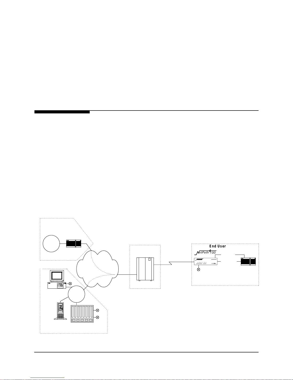
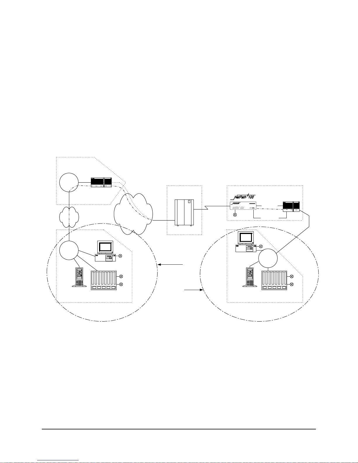
The NetPath 100 Frame Relay Channel Service Unit (FSU) is a special purpose
T1/FT1 CSU/DSU which provides management and diagnostic functions through
Simple Network Management Protocol (SNMP), transported over a Frame Relay
network. It also includes an integral modem which supports access to the CSU/DSU
as well as other co-located equipment such as routers. The NetPath 100 can be factory
optioned to include an ISDN Adapter (4 BRIs, for Backup and/or Bandwidth OnDemand). Network Service Providers (NSPs) who prefer to have independent
management access from their end-user networks (customer networks), can utilize the
isolated management PVC desi gned into the NetPath 100 f or network demarcation and
diagnostics.
System Level
Customer Data
Center
Customer
LAN
Router
Frame Relay
NCC Telnet
Work Station
NCC
LAN
Backbone
Figure 2-1 shows a system level view of the Ne tPath 100 FSU, including man agement
transport. As shown in the figure, the Frame Relay network provides Permanent
Virtual Circuits (PVCs) for both the Customer Data and FSU m anag ement.
NOTE: NetPath 100 is transparent to SVCs (Switched Virtual Circuits).
The NetPath 100 can have up to two IP Addresses for management. One IP Address
allows it to communicate with SNMP work stations that have access to the NSP
management PVC. A second IP Address can provide management access via a
customer data PVC.
NetPath 100 can also send SNMP Traps to mu ltiple SNMP Alarm Servers via the man agement PVCs. The integral modem is used to dial into the Network Control Center
(NCC) Terminal Server to access the SNMP Alarm Server and report faults that are
prevented from being reported over the PVC management chan nels. It can also accept
maintenance calls from NCC Work Stations to support operator interaction, and accept
inbound calls from a customer or NCC Work Station to manage co-located devices
such as routers.
End Us er Prem ise
HW3DWK
Dial Line
Serial Po rt
(Cus t . PVC )
Console Port
Router
Cust.
PVCs
Mgmt
PVC
IP Over
Frame
POP
Frame Sw itch
Customer &
Mgmt PVCs
SNMP Alarm
Server
Network Control Center
Terminal Server
Figure 2-1 NetPath 100 Typical Network Application
980-001-0210G NetPath 100 User’s Manual - Installation Guide 2-1
1999
June
2 Description
ISDN Adapter
Option
ISDN Backup
IP Ma n agement
Network
Control
The NetPath 100 can be factory-optioned to include an integral ISDN Adapter module.
The ISDN adapter includes four “U” ISDN TA Interfaces with two integral NT1 In-
verse Multiplexers, thereby providing up to 512 Kbps of switched connectivity for network Backup and/or additional Bandwidth On-Demand.
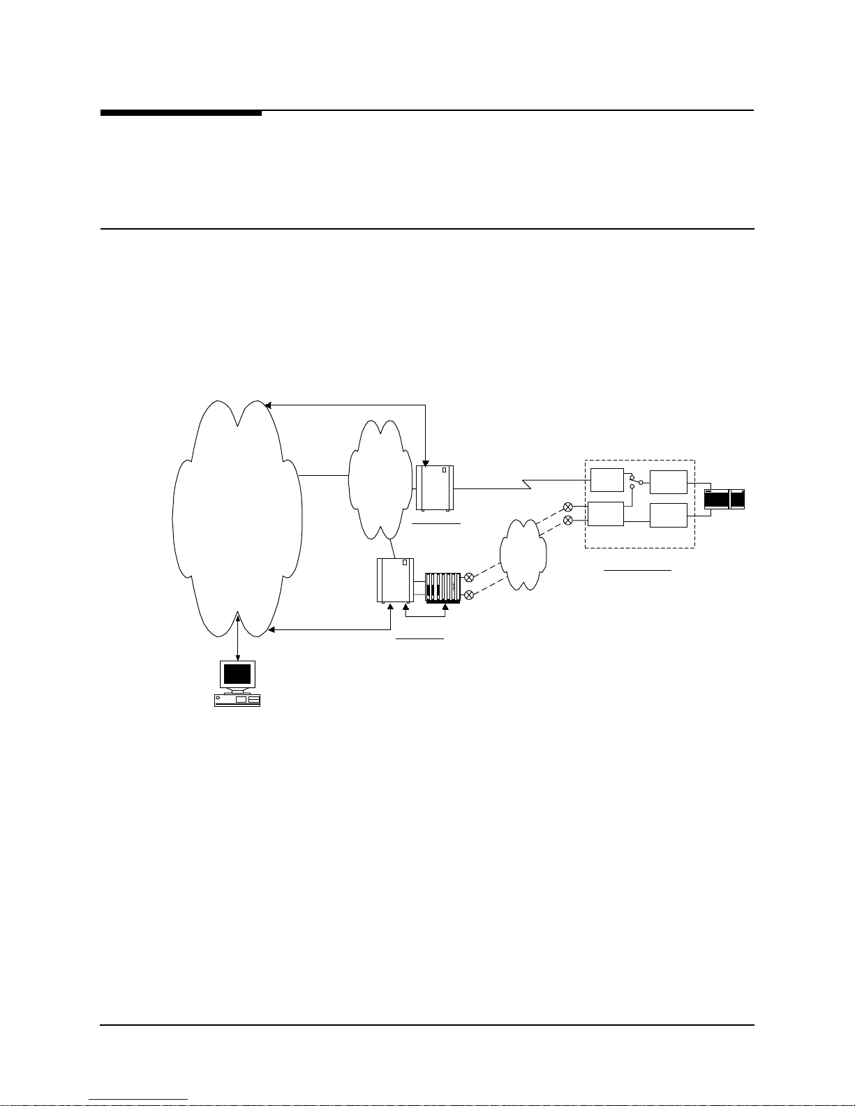
Backup in Frame Relay Protocol utilizing the Router’s Primary Port can be via dedi-
cated PVCs on an alternate port, or the frame switch manag er may reroute the or iginal
PVCs to the Backup Frame Switch. It is also possible to b ypass the entire Frame Relay
Network and initiate backup to a pool of ports on an alternate Frame Switch connected
directly to another Router.
A typical network configuration showing the backup connection to a Backup Frame
Switch using rerouted PVCs is shown in Figure 2-2.
F/S Control
NP 10 0 D ata
& Control
F/S & IMux Control
Frame
Backbone
Backup
Frame
Switch
Frame
Switch
Prim ary Node
Inv e r s e
Mult i plexer
Control
Backup Node
NP 10 0 D ata
& Control
PRI 1
PRI 4
IS DN
BRI 1
BRI 4
CSU
IS DN
NetPath 100
Customer Location
V.35
Data
On
Demand
Router
Work Station
Figure 2-2 Typical Backup Configuration
The backup process is described as follows:
2-2 NetPath 100 User’s Manual - Installation Guide 980-001-0210G
•
NetPath 100 detects loss of connectivity at CSU.
•
ISDN Adapter card calls Backup Frame Switch and is identified by caller ID.
•
Frame Switch Manager either reroutes original PVCs, or Frame Switch uses
alternate PVCs for the backup connection.
•
NetPath 100 switches the data path when connected.
•
Associated routers determine that PVCs have been established through LMI
enquiries.
•
Communication is resumed.
June
1999

2 Description
Frame Relay Cloud
ISDN Cloud
Router
CSU
Router
TATATA
TA
Bandwidth
On Demand
Bonding
Mode 1 or MLPPP
ISDN Bandwidth
On-Demand
Bandwidth On-Demand provides an additional network connection for a second DTE
(router) port based on a request from the DTE. In this configuration the NetPath 100
ISDN Adapter is protocol-transparent. The Router determines the protocol used.
A typical network configuration showing simultaneou s Bandwidth On-Demand and
Backup connections is shown in Figure 2-3.
HW3DWK
Backup Switch
Switch
Primary Switch
NetPath 100
Figure 2-3 Typical Simultaneous Bandwidth On-Demand Configuration
The bandwidth on-demand process is described as follows:
•
User’s router detects need for bandwidth and raises DTR on its second port.
•
NetPath 100 ISDN Adapter calls predetermined number.
•
The Central Router answers the call and establishes communications with the
remote Router.
•
Communication commences between Routers.
•
User’s Router lowers DTR to terminate the ISDN connection when the
“demand” has been satisfied.
980-001-0210G NetPath 100 User’s Manual - Installation Guide 2-3
1999
June
2 Description
NetPath 100
The basic NetPath 100 includes a T1 interface, network-compliant Fractional Rate to
Full Rate CSU/DSU, a Frame Relay switch function, a Frame Relay management
module, and an SNMP Agent.
The unit also includes two Auxiliary ports and may be factory-optioned to include an
internal V.32bis or V.34-compliant mod em. An integral call director con nects the modem to the CSU, AUX 1 port, AUX 2 port, or Option module (ISDN) based on a
DTMF code sent by the caller. All the devices can access the modem for call-out purposes on a first-come, first-served basis.
System software can be downloaded to the NetPath 100 for upgrades.
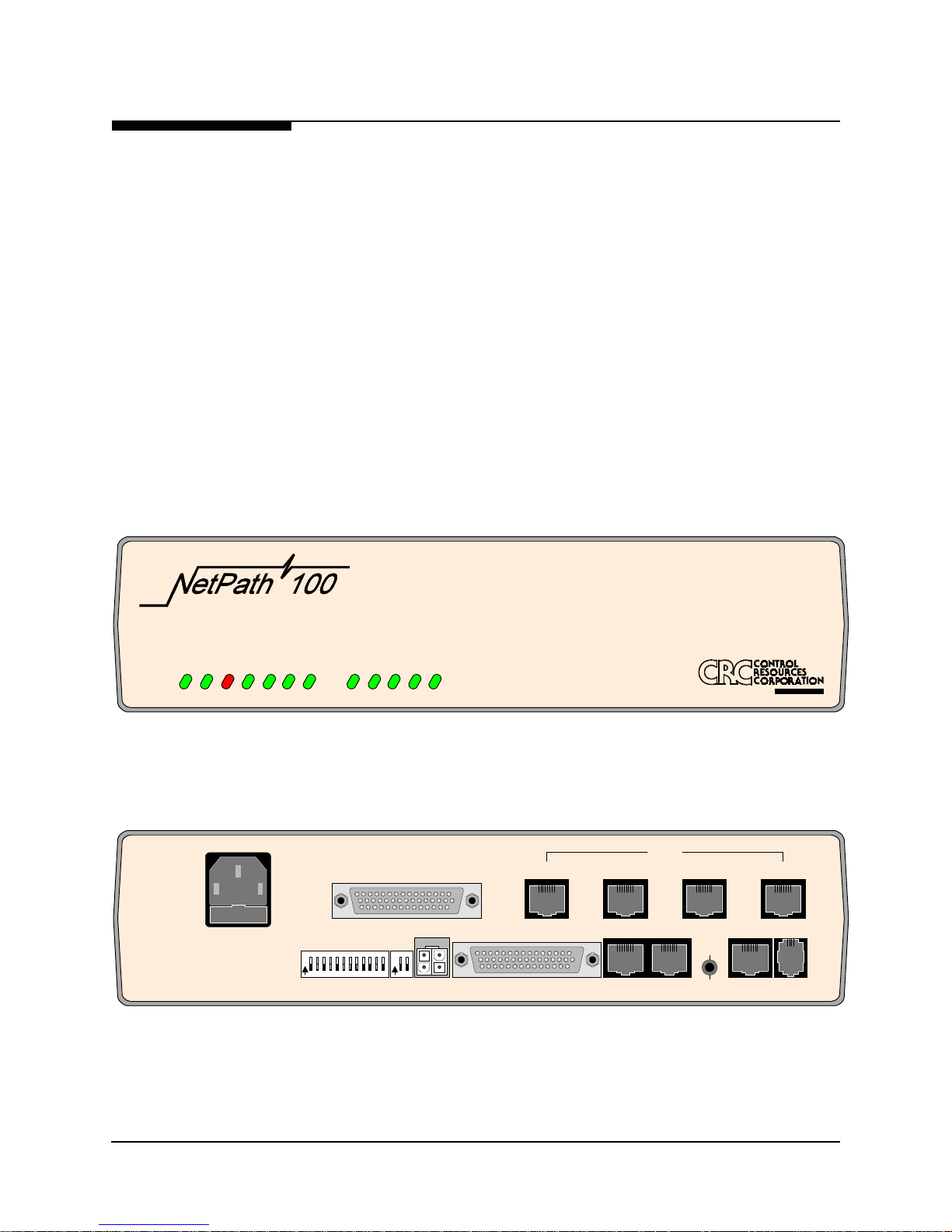
The front and rear panels of the basic NetPath 100 are shown in Figure 2-4 and
Figure 2-5.
Detailed descriptions of the NetPath 100 indicators and controls are provided in section 5 Diagnostics o f thi s man ual. C on nector and pinout details are provided in Installation, Section 3 of this manual.
Frame Relay CSU
HS PORT TxD
READY
T1 ALARM
POWER
HS PORT RxD
Figure 2-4 NetPath 100 Front Panel (shown with ISDN option)
90-250 VAC
.5A
50-60 Hz
FUSE
2A/250V
SLOW BLOW
5x20mm
FOR CONTINUED PROTECTION AG AINST RISK OF FIRE,
REPLACE ONLY WITH SAM E TYP E AND RAT ING OF FUS E.
"CAUTION"
Figure 2-5 NetPath 100 Rear Panel (shown with ISDN option)
MODEM IN USE
FR MGMT.
O
123456789101112
N
CONFIGURATION
ISDN READY
LINE 2 STATUS
LINE 1 STATUS
O
12
N
LINE 3 STATUS
CONTROL
OUTPUT
LINE 4 STATUS
LINE 1ISDN DATA PORT
DATA PORT
ISDN
AUX 1 AUX 2
A
P-COM
NVM
RESET
CONFIG
Company
T1
LINE
LINE 4LINE 3LINE 2
MODEM
LINE
2-4 NetPath 100 User’s Manual - Installation Guide 980-001-0210G
June
1999
2 Description
Power Control
Unit Option
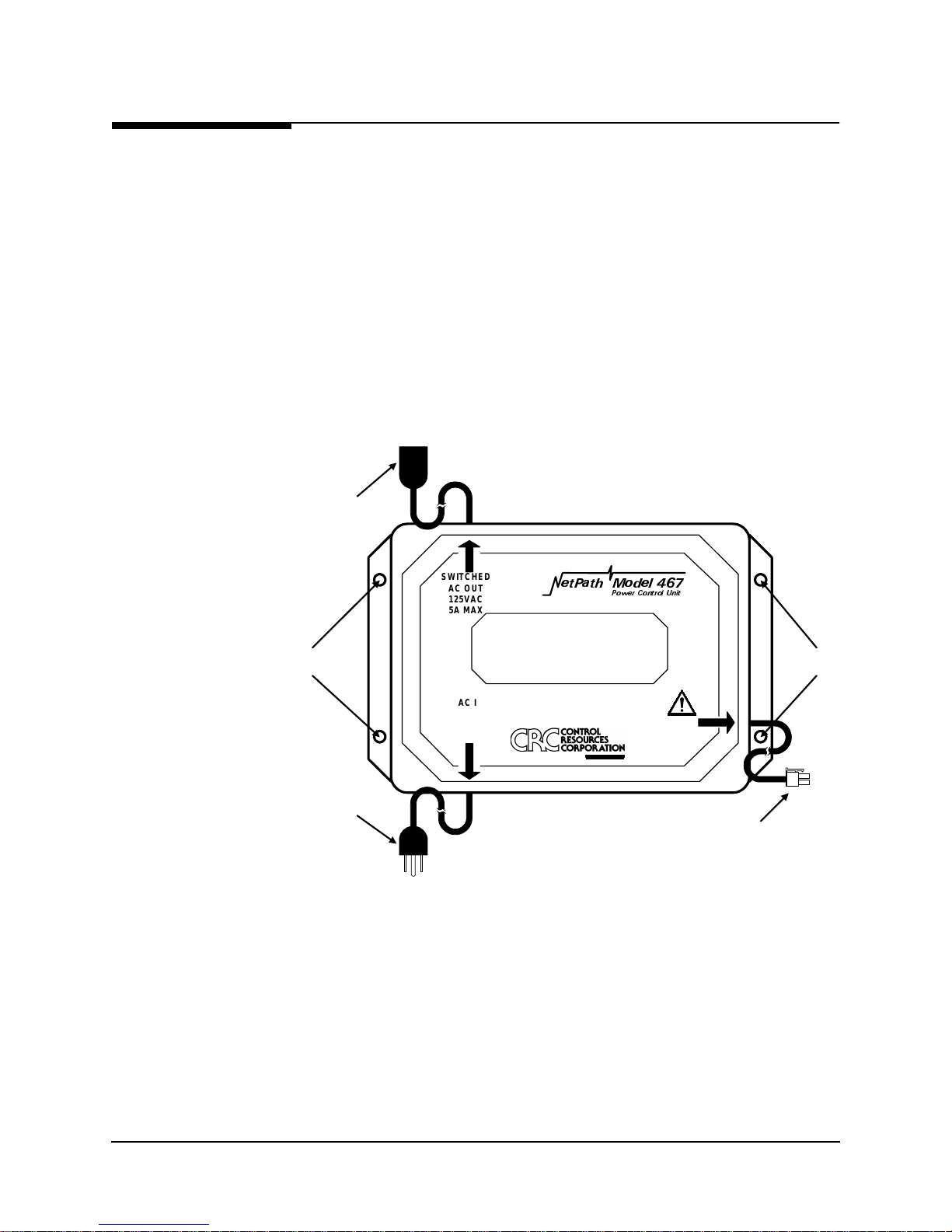
The optional external Mo del 467 Power Cont rol Unit (PCU) pr ovides a mechani sm for
rebooting an external device by momentarily disrupting its AC power source.
The unit is a stand-alone enclosur e which consists of an AC power relay, relay con trol
circuit, power transfor mer, AC IN po wer plug /cord , AC OUT po wer s ocket/cor d, and
NetPath power/control cable.
The PCU responds to an operator command to disrupt power to the connected device
for a duration of one (1) to 3 0 secon ds . When commanded, the PCU disrupts both th e
Hot and Neutral power leads.
The PCU can be wall-mounted using the four mounting holes shown in Figure 2-6.
AC O UT
Socket
SWITCHED
AC OUT
125VAC
5A MAX
HW3DWK 0RGHO
3RZHU &RQWURO 8QLW
WARNING!
Mounting
Holes
NO USER SERVICEABLE PARTS INS IDE
HIGH INTERNAL VOLTAGES PRESENT
INTERNAL SHO CK HAZARD PRESENT
Mounting
Holes
AC IN
Plug
AC IN
125VAC
5.5AMPS MAX
50-60Hz
A
P-COM
Company
SEE
USERS
MANUAL
Po w e r/Co n tro l
Connector
(4-Pin, Keyed, Locking)
Figure 2-6 Model 467 Power Control Unit
980-001-0210G NetPath 100 User’s Manual - Installation Guide 2-5
1999
June

2 Description
Operating
Features
Management
Access
Password Security
This section contains operation information about the following:
•
Management Access
•
Software Download
•
Trap Reporting
•
Modem & Call Director
Management access for control sessions or to retrieve alarm status is provided to the
NetPath 100 via in-band Telnet, dial-in VT-100 console connection or direct-connected VT-100 terminal. NetPath 100 also supports SNMP “Get,” “Get Next,” and “Set”
commands for retrieval of configurations and statistics information.
Security is provided through five levels of password-protected access.
System Screen
Displays
Level 1, System Access Password:
Allows access to system login via User Access Passwords.
Levels 2 - 5, User Access Passwords:
View - Allows user to display all screens.
Test - Allows user to perform diagnostic tests from Status / Test screens and
allows View password access.
Configuration - Allows user to change operating parameters and allows Test
password access.
Supervisor - Grants unlimited access including the viewing and changing of
passwords.
Once successfully logged in, the system provides screen displays for configuration,
testing, and performance statistics. Help text describing each screen’s display fields
and commands are also provided.
2-6 NetPath 100 User’s Manual - Installation Guide 980-001-0210G
June
1999

2 Description
WAN DLCI
Management
IP Addressing
Customer Data
Center
The in-band Frame Relay Management Cha nnel WAN address is defined by th e DLCI
(Data Link Connection Identifier). The WAN DLCI can be configured for a Dedicated
PVC, or as a Tunneled channel within a Payload PVC. During initial installation the
WAN DLCI can be set via the unit’s rear panel Configuration DIP Switches, Local
Console Port or Dial-In Console Port. Thereafter the DLCI can also be changed vi a inband management access.
NetPath 100 has special features for Network Service Providers (NSPs) who require
management access to the FSU to be isolated from the payload data. This isolated access is provided either by NetPath 100’s ded icated network-facing management PVC
as shown in Figure 2-1 or by the Tunneled management channel on a network-facing
Payload PVC as shown in Figure 2-7.
Customer
LAN
Router
NetPath 100
NCC Telnet
Work Station
SNMP Alarm
Server
NCC
LAN
Terminal Server
Network Control Center
HUB
Group
Mgmt
PVC
Frame Relay
Backbone
Cust.
PVCs
IP O v e r
Frame
POP
Frame Sw itch
Customer &
Mgmt PVCs
End Us er Prem ise
Serial Po rt
(Cus t . PVC )
Console Port
Dial Line
Figure 2-7 Tunneled Management
Tunnel management is accomplished by a NetPath HUB (NetPath100 class unit) located at a site which supports up to 48 PVCs connected to NetPath units located at remote
(spoke) sites. The HUB unit per for ms the rout ing and en capsulat ion funct ion for man agement channel messages going to and from the remote units. The HUB is connected
to the network manageme nt syste ms by a sepa rate de dicated g roup man agement P VC.
Router
980-001-0210G NetPath 100 User’s Manual - Installation Guide 2-7
1999
June
2 Description
Customer Data
Center
Customer
LAN
Mgmt
Router
NetPath 100 also provides expanded management access to the FSU through the following features:
•
Support for two IP Addresses.
•
An optional network-facing management channel via a specified IP Address
on a specified payload PVC.
•
An optional CPE-facing dedicated PVC management channel.
These optional management paths are shown in Figure 2-8.
End User Premise
Serial Port
(Cu s t. P VC )
Dial Line
Console Port
Router
Frame R elay
Backbone
Cust.
PVCs
IP O v e r
Frame
POP
Frame Sw itch
Customer &
Mgmt PVCs
NCC
LAN
NCC Telnet
W ork S ta t io n
SNMP Alarm
Server
Terminal Server
Netw ork Control Center
NCC Telnet
Payloa d
W ork S ta t io n
OR
CPE
SNMP Alarm
Server
Netw ork Control Center
Figure 2-8 Payload / CPE Management
NCC
LAN
Terminal Server
Mgmt
2-8 NetPath 100 User’s Manual - Installation Guide 980-001-0210G
June
1999

2 Description
With these features, NSP and/or customer management of the FSU can be accomplished through three basic management modes:
•
The primary IP Address is associated with the network-facing dedicated PVC
or Tunneled payload PVC. In this mode, there may be a secondary IP Address.
The secondary IP Address can be associated with a specified payload PVC or a
dedicated CPE-facing PVC.
•
The primary IP Address is associated with a specified payload PVC. There is
no secondary IP Address.
•
The Primary IP Address is associated with a dedicated CPE-facing PVC. There
is no secondary IP Address.
980-001-0210G NetPath 100 User’s Manual - Installation Guide 2-9
1999
June

2 Description
WAN Management
IP Address
NetPath 100 utilizes one IP Address on the dedi cated, network-facing Wide Area Network (WAN) management channel. This address is embedded within the various communications protocol stacks used for SNMP, Telnet and PPP. The unit’s WAN
Management IP Address may be automatically learned from the first message received
on the management PVC, or it can be set via the local or remote Console Port.
When optioned with ISDN, NetPath 100 can have several communications paths that
allow the management channel to connect to the frame relay network in different places. Each of these connection points could result in the management PVC routing
through different IP sub-nets to reach the Network Control Center, or it may be desirable to have the NetPath 100 appear as a logically different object in the SNMP manager, especially if static routing and dedicated backup ports are utilized. The setting/
learning of these additional IP Addresses is described in detail in S ection 4, “Config-
uration,” in this manual.
NetPath 100 will retain in Non-Volatile Memory (NVM), a separate WAN IP Address
for each connection point. All communications via OOB PPP (Out-Of-Band Point-toPoint Protocol) will utilize whatever IP Address is in effect depending on how the unit
is currently connected to the network. There are several options for establishing the
WAN IP Address within the NetPath 100.
When the unit is shipped from the factory or when NVM is cleared on initial installation, the WAN IP Address for each connection point is set to 00 0.0 00.0 00.000 , wh ich
indicates no address is known.
The WAN IP Address to be used on the T1 link is automaticall y “learned” from the
first valid IP message received over the unit’s management PVC. Learning will take
place as long as the value of the WAN IP Address in NVM is 000.000.000.000. Once
the IP Address is set or learned it is retained and used until the NVM is cleared or another addre s s is manually set.
Software
Download
Trap Reporting
2-10 NetPath 100 User’s Manual - Installation Guide 980-001-0210G
The NetPath 100 system software (fi rmware) is stored in flas h memory. A new version
of the software can be downlo aded t o the un it f or s of twar e upg rade, or for restoration
in the event an error is detected in the flash storage.
A description of the software download process is provided in Section 5, “Diagnos-
tics,” of this manual.
The NetPath 100 provides an MIB which includes standard MIB-II groups and also
contains a Private MIB Extension which supports the issuance of unique Traps. Traps
are issued either in-band or dial-ou t (out-of-band) via the on- board modem, depending
on the specific fault detected.
Section 5 Diagnostics of this manu al lists the MIB objects and the T r ap reporting path
for each.
June
1999

2 Description
Modem &
Call Director
Dial
Line
The integral on-board modem can be switched to any one of the interfaces of the NetPath 100 by the call director. The call director conn ects the modem to the Base module,
Optional ISDN Adapter module, AUX 1 Port, or AUX 2 Port.
In this way, the modem is used for out-of-band trap reporting (NetPath 100 Base module, Option module or DTE device connected to an AUX Port) and accepts incoming
calls for management access of the NetPath 100, DTE device or any other device connected to an AUX Port.
Figure 2-9 shows a block diagram of the Modem and Call Director.
DTMF Det
Line
inte rf a c e
Dial
Tone Gen
Modem
Ca ll Dire c to r
Base
Option
Aux 1
Aux 2
Figure 2-9 Modem & Call Director Block Diagram
On incoming calls, the modem-to-interface assignment is made based on the DTMF
code detected after the NetPath 100 line interface goes off-hook and returns a second
Dial Tone.
DTMF code selections are shown in Table 1.
Table 2-1. Call Director DTMF Codes
Interface DTMF Code
Base module (CSU) 1
Aux 1 Port 2
Aux 2 Port 3
Option Adapter Module 4
Defaults to Base
module after timeout.
Modem parameters may be modified in the database as part of the configuration.
All Others
The configuration also includes a periodic self-test option for the modem and a dial
tone test for the dial line (performed every four hours), with results indicated on the
status screen, and failures reported as a Trap on the dedicated facility.
980-001-0210G NetPath 100 User’s Manual - Installation Guide 2-11
1999
June

2 Description
2-12 NetPath 100 User’s Manual - Installation Guide 980-001-0210G
June
1999

3 Installation
g
This section contains information to complete the physical installation of a
NetPath 100 which includes: mounting the unit, power connection, and input/output
connections.
Mounting
NetPath 100 comes equipped with rubber feet for table o r shelf-top placement. Optional adapter brackets are available for wall mounting and standard 19" or 24" rack
mounting. Sufficient space for cooling and access to th e front panel indicators for trou bleshooting are required in all installations.
CAUTION
Failure to provide adequate cooling space may overheat
the unit and void the warranty.
1. Before unpacking, ensure that the factory carton does not show any signs of
damage. If it does, contact the freight carrier immediately.
2. Unpack the NetPath 100 and power cord from the factory carton(s). Check all the
components for signs of damage. If they appear damaged, contact your equipment
provider before proceeding.
3. Mount the NetPath 100 in its operating location. Table-top or shelf-top location is
assumed in this manual.
CAUTION
Select a location where the unit will not be disturbed
once it is operational. Do not place the NetPath 100 on
top of any heat-producin
other equipment on top of the NetPath 100.
equipment. Do not place any
To Wall-Mount or Rack-Mount the NetPath 100 , follow the in structions supp lied with
the Wall or Rack mount adapter.
980-001-0210G NetPath 100 User’s Manual - Installation Guide 3-1
1999
June

3 Installation
Mounting
Optional
Model 467
Power Control
Unit
The external Power Control Unit may be wall-mou nted using the four mount ing holes
provided on its base (refer to Figure 2-6).
NOTE: Use wall fasteners appropriate for the wall’s surface material, i.e. wood
screws for wooden surfaces, ex pansion f asteners for g ypsum wall b oard, etc.
The Power Control Unit may also be placed or moun te d on a t abl e-top , s hel f, o r fl oo r
near the NetPath 100.
CAUTION
The Power Control Unit must not be placed where the unit or its
cables may be bumped, kicked or walked on.
3-2 NetPath 100 User’s Manual - Installation Guide 980-001-0210G
June
1999

3 Installation
Connections
NetPath 100 has connectors on the rear panel for power and input/output connections.
Rear panel connectors and controls are shown and described in Figure 3-10 and
Table 3-1.
90-250 VAC
.5A
50-60 Hz
FUSE
2A/250V
SLOW BLOW
5x20mm
FOR CONT INUED PROT EC TION AGAINST RISK OF FIRE,
REPLACE ONLY WITH SAM E TYP E AND RAT ING OF FU SE.
"CAUTION"
O
123456789101112
N
CONFIGURATION
O
12
N
CONTROL
OUTPUT
DATA PORT
AUX 1 AUX 2
NVM
RESET
CONFIG
Figure 3-10 NetPath 100 Rear Panel (Basic)
Table 3-1 Basic NetPath 100 Input/Output Connectors and Control Specifications
T1
LINE
MODEM
LINE
Connectors Description
Power Connector Internal Power Supply with IEC 320 power cord.
Control Output 4-pin keyed connector to control Model 467 Power Control Unit.
Data Port DB-44, high-density connectors provide the following interfaces,
selected by the interface cable used:
EIA-530
EIA-530-A
ITU-V.35
ITU-X.21-NS (Non-Switched)
AUX 1, AUX 2 8-pin modular connectors, EIA-232
NVM Reset/Config Recessed push button that causes the unit’s NVM to be cleared if pressed and held
(approximately four seconds) during the unit’s power-up self-test.
T1 Line 8-pin modular connector, RJ48C
Modem Line (Analog) 6-pin modular connector, RJ11C
DIP Switches One 2-position and one 12-position DIP switch for the initial setting of th e DLCI
address, the DS0 configuration for the T1 link, and the CSU/DTE parameters.
980-001-0210G NetPath 100 User’s Manual - Installation Guide 3-3
1999
June

3 Installation
DATA PORT
CONFIGURATION
ON123456789101112ON1
2
FUSE
2A/250V
SLOW BLOW
5x20mm
90-250 VAC
.5A
50-60 Hz
CONTROL
OUTPUT
FOR CONTINUED PROTECTION AG AINST RISK OF FIRE,
REPLACE ONLY WITH SAM E TYP E AND RAT ING OF FUS E.
"CAUTION"
Power
Connections
NetPath 100
Power
1. The NetPath 100 includes an internal universal Power Supply. Plug the IEC 320
end of the Power Cord into the con nector on the rear of the NetPath 100, shown in
Figure 3-11.
AC Power Connector
(IEC 320)
Figure 3-1 1 NetPath 100 Power Co nnection
Power On
Self Test
2. Verify that the proper voltage (90 - 250 VAC, 50 - 60 Hz) is present at the outlet to
be used. If the outlet voltage is correct, plug the other end of the Power Cord into
the AC outlet.
3. Once connected, the NetPath 100 will go through the following normal power up
sequence:
Basic NetPath 100
a. The POWER LED will light immediately and stay on.
b. The READY LED will flash while the unit performs its self-test (test
duration - a pproximately 45 seconds).
c. The READY LED will be ON steady after successful completion of
the self-test.
d. The T1 ALARM and FR MGMT. LEDs should not be flashing
together.
e. All other LED indications should be ignored at this time.
3-4 NetPath 100 User’s Manual - Installation Guide 980-001-0210G
June
1999

3 Installation
g
g
NetPath 100 with ISDN
a. The POWER LED will light immediately and stay on.
b. The READY and ISDN READY LEDs will flash while the unit per-
forms its self-test (test duration - approximately 45 seconds).
c. The READY and ISDN READY LEDs will be ON steady after suc-
cessful completion of the self-test.
d. The T1 ALARM and FR MGMT. LEDs should not be flashing
together.
e. All other LED indications should be ignored at this time.
If the LED indications are not as d escribed above, refer to section 5 Diagnostics of this
manual.
If operation looks normal, unplug the NetPath 100 and make the required data input/
output connections. If an optional Power Control Unit is to be installed with this NetPath 100, proceed to the next page of this manual. Otherwise, skip this page and go the
Input/Output Connections section.
NOTE: The NetPath 100 does not have a Power ON/OFF switch. To remove power
from the NetPath 100, disconnect the Power Cord from the AC outlet.
CAUTION
CRC recommends that you remove AC power from the
NetPath 100 before attachin
durin
the installation process.
input and output cables
980-001-0210G NetPath 100 User’s Manual - Installation Guide 3-5
1999
June

3 Installation
g
y
g
(
g)
p
p
Optional Power
Control Unit Power
Connection
Co nn e ct DT E A C Input
NetPath Controlled Power
Three connections are required to install an optional Model 467 Power Control Unit.
A. Connect the device to be controlled (usually the DTE connected to the NetPath
100) to the Switched AC OUT Socket (125 VAC) of the Power Control Unit
shown in Figure 3-12 below.
CAUTION
Do not plug the power cord from the NetPath 100 into the
AC OUT socket of the Power Control Unit. This is an
invalid confi
uration.
B. Connect the Power/Contro l C abl e f rom t he P owe r Co nt rol Unit shown in Figure 3-
12 to the Control Output connector on th e rear p anel o f the NetPath 1 00 (s ho wn in
Figure 3-11).
C. Verify that the proper voltage is present at the outlet to be used (90 - 125 VAC,
50 - 60 Hz). If the outlet voltage is correct, plug the AC IN Plug from the Power
Control Unit into the AC outlet.
here for
AC O U T
Socket
AC IN
Plu
SWITCHED
AC OUT
125VAC
5A MAX
HW3DWK 0RGHO
3RZHU &RQWURO 8QLW
WARNING!
NO USER SERVICEABLE PARTS INSIDE
HIGH INTERNAL VOLTAGES PRESENT
INTERNAL SHOCK HAZARD PRESENT
AC IN
125VAC
5.5 AMPS MAX
50-60Hz
A P-COM Compan
SEE
USERS
MANUAL
Connect to
ut Connector
anel
Power/Con trol
Control Out
on NetPath 100 rear
Connector
4-Pin, Keyed, Lockin
Figure 3-12 Power Control Unit Connections
Continue the installation by making Input/Output connections and Configuring the
NetPath 100 as described in the following sections of this manual.
3-6 NetPath 100 User’s Manual - Installation Guide 980-001-0210G
June
1999

3 Installation
g
g
Input/Output
Connections
T1 Line
Connection
Basic NetPath 100 has inp ut/outp ut connect ors for the T1 Line, Dat a Port (DTE), two
AUX ports, and Modem Line. Pinouts for each of the these ports are provided in the
tables that follow.
NOTE: Refer to section 6 Options of this manual for a description of additional connectors for options such as ISDN Adapter.
CAUTION
The installer must ensure that the plugs connecting the
T1 Line to the NetPath 100 are matchin
modular plu
connection of the T1 Line to either of the NetPath 100
AUX connectors.
Use CRC cable assembly # 135-982-0006, or per pinout shown in Table 3-2.
s. This will prevent the accidental
“keyed”
Table 3-2 T1 Line Pinout, RJ48C Connector
18
T1 Line
Data Port Interface
& Cable Codes
Pin Description Direction
1 R1 (Ring 1) Receive
2 T1 (Tip 1) Receive
3,6 No Connection N/A
4R (Ring) Transmit
5T (Tip) Transmit
7,8 Frame Ground N/A
NOTE: Use Twisted Pair Cable conductors for pins: 1 & 2, 4 & 5, and 7 & 8.
The NetPath 100 Data Port (DTE) supports four electrical interface types; ITU-V.35,
EIA-530, EIA-530-A and ITU-X.21-NS. The Data Port connector on the back of the
NetPath 100 is a DB-44 high density female. A short (approx. 2.5 ft.) adapter cable is
used to convert from the DB-44 to the appropriate connector type for the interface selected. The adapter cable also includes a unique Cable Code (CBC), a special wiring
pattern at the DB-44 connector, which automatically sets the port to the desired interface type.
NOTE: Some manufacturer specific cab le pinouts are provid ed at the end of th is manual section, under General Specifications.
980-001-0210G NetPath 100 User’s Manual - Installation Guide 3-7
1999
June

3 Installation
g
Data Port Pinout
Table 3-3 shows the pinout for the Data Port connector.
Table 3-4 through Table 3-7 show the pin connections for the adapter cables for each
of the interface types.
.
Table 3-3 Data Port Pinout DB-44F Connector
Pin Si
1Shield N/A 23 DCD-A Output
2NC
3NC
4 RTS(s) Input 26 CBC-A* N/A
5 CTS(s) Output
6 DSR(s) Output
7 Sig. Gnd. N/A 29 TCE-A Input
8 DCD(s) Output
9 DTR(s) Input
10 NC 32 TD-B Input
nal Direction Pin Signal Direction
24 DTR-A Input
25 TC-A Output
27 RC-A Output
28 CBC-B* N/A
30 CBC-C* N/A
31 Shield N/A
11 NC
12 NC
13 NC 35 CTS-B Output
14 NC
15 NC
16 Shield N/A 38 DCD-B Output
17 TD-A Input
18 RD-A Output
19 RTS-A Input 41 NC
20 CTS-A Output
21 DSR-A Output
22 Sig. Gnd. N/A 44 TCE-B Input
Notes: *CBC = Cable Code pin.
(s) = single ended.
33 RD-B Output
34 RTS-B Input
36 DSR-B Output
37 Sig. Gnd. N/A
39 DTR-B Input
40 TC-B Output
42 RC-B Output
43 NC
3-8 NetPath 100 User’s Manual - Installation Guide 980-001-0210G
June
1999

3 Installation
g
ITU-V.35 Adapter
Use CRC cable assembly # 135-001-0400, or per pinout shown in Table 3-4.
Cable
Table 3-4 ITU-V. 35 Interface Adapter Cable (CBC=1)
M-34F
Pin
A1ShieldN/A U 29 TCE-A Input
B 7 Sig. Gnd. N/A
C 4 RTS(s) Input W 44 TCE-B Input
D5CTS(s)Output
E 6 DSR(s) Output
F 8 DCD(s) Output Z
G
H 9 DTR(s) Input
J
DB-44M
Pin
I CC
Si
nal Direction
M-34F
Pin
V 27 RC-A Output
X 42 RC-B Output
Y 25 TC-A Output
AA 40 TC-B Output
BB
DD
DB-44M
Pin
Signal Direction
K
L FF
M
N
O II
P 17 TD-A Input
Q
R 18 R D-A Output LL
S 32 TD-B Input
T 33 RD-B Output
Notes: *CBC = Cable Code pin.
(s) = single ended.
Twisted Pair cable conductors for: TD-A & B, RD-A & B, TC-A & B, RC-A & B and TCE-A & B.
Install 300 Ohm, 1/4W, 5% resistors at DB-44 end across pi ns: 17 to 37, 32 to 37, 29 to 22, and 44 to 22.
Shielded cable is recommended.
EE
GG
HH
JJ
KK
MM
NN
26 CBC-A* N/A
28 to 22 CBC-B* N/A
30 to 22 CBC-C* N/A
980-001-0210G NetPath 100 User’s Manual - Installation Guide 3-9
1999
June

3 Installation
g
EIA-530 Adapter
Use CRC cable assembly # 135-002-0400, or per pinout shown in Table 3-5.
Cable
Table 3-5 EIA-530 Interface Adapter Cable (CBC=2)
DB-25F
Pin
116ShieldN/A 14 32 TD-B Input
2 17 TD-A Input
3 18 RD-A Output
4 19 RTS-A Input 17 27 RC-A Output
520CTS-AOutput
621DSR-AOutput
7 22 Sig. Gnd. N/A 20 24 DTR-A Input
823DCD-AOutput
9 42 RC-B Output
DB-44M
Pin
nal Direction
Si
DB-25F
Pin
15 25 TC-A Output
16 33 RD-B Output
18
19 34 RTS-B Input
21
22 36 DSR-B Output
DB-44M
Pin
Signal Direction
10 38 DCD-B Output 23 39 DTR-B Input
11 44 TCE-B Input
12 40 TC-B Output
13 35 CTS-B Output
Notes: *CBC = Cable Code pin.
(s) = single ended.
Twisted Pair cable conductors for: T D-A & B, RD-A & B, RTS-A & B, CTS-A & B, DSR-A & B,
DCD-A & B, DTR-A & B, TC-A & B, RC-A & B and TCE-A & B.
Shielded cable is recommended.
24 29 TCE-A Input
25
26 to 22 CBC-A* Cable Code - A
28 CBC-B* Cable Code - B
30 to 22 CBC-C* Cable Code - C
3-10 NetPath 100 User’s Manual - Installation Guide 980-001-0210G
June
1999

3 Installation
g
EIA-530-A Adapter
Use CRC cable assembly # 135-003-0400, or per pinout shown in Table 3-6.
Cable
Table 3-6 EIA-530-A Interface Adapter Cable (CBC=3)
DB-25F
Pin
116ShieldN/A 14 32 TD-B Input
2 17 TD-A Input 15 25 TC-A Output
3 18 RD-A Output
4 19 RTS-A Input
520CTS-AOutput 18
6 6 DSR(s) Output
7 22 Sig. Gnd. N/A
823DCD-AOutput 21
9 42 RC-B Output
DB-44M
Pin
nal Direction
Si
DB-25F
Pin
16 33 RD-B Output
17 27 RC-A Output
19 34 RTS-B Input
20 9 DTR(s) Input
22
DB-44M
Pin
Signal Direction
10 38 DCD-B Output
11 44 TCE-B Input 24 29 TCE-A Input
12 40 TC-B Output
13 35 CTS-B Output
Notes: *CBC = Cable Code pin.
(s) = single ended.
Twisted Pair cable conductors for: TD-A & B, RD-A & B, RTS-A & B, CTS-A & B,
DCD-A & B, TC-A & B, RC-A & B and TCE-A & B.
Install 470 Ohm resistor at DB-44 end across pins: 9 to 37.
Shielded cable is recommended.
23
25
26 CBC-A* N/A
28 CBC-B* N/A
30 to 22 CBC-C* N/A
980-001-0210G NetPath 100 User’s Manual - Installation Guide 3-11
1999
June

3 Installation
g
g
ITU-X.21-NS
Adapter Cable
Use CRC cable assembly # 135-005-0400, or per pinout shown in Table 3-7.
ITU-X.21-NS (NS indicates Non-Switched)
Table 3-7 ITU-X.21-NS Interface Adapter Cable (CBC=4)
DB-15F
Pin
116Shield N/A 9 32 TD-B Input
2 17 TD-A Input 10 34 Control-B Input
3 19 Control-A Input
4 18 RD-A Output
5 23 Indication-A Output 13 40 TC-B Output
6 25 TC-A Output
7
8 22 Sig. Gnd. N/A
DB-44M
Pin
nal Direction
Si
DB-15F
Pin
11 33 RD-B Output
12 38 Indication-B Output
14
15
DB-44M
Pin
26 to 22 CBC-A* N/A
Signal Direction
Notes: *CBC = Cable Code pin.
(s) = single ended.
Twisted Pair cable conductors for: TD-A & B, RD-A & B, Control-A & B, Indication-A & B, and RC-A & B.
DTR signal and DTE timing are not supported in ITU-X.21-NS mode.
Shielded cable is recommended.
AUX 1 & AUX 2
Connections
28 to 22 CBC-B* N/A
30 CBC-C* N/A
AUX Ports can be used to access other equipment through the NetPath dial line. For
example, the console port of the DTE device (Router, FRAD, etc.) connected to the
NetPath can be connected to an AUX Port.
Use CRC cable assembly # 135-008-0400 for modular to DB25, or # 135-990- 0006 for
modular to Cisco* rout er cons ol e, o r p er p in ou ts s ho wn i n th e t abl es on the next page.
* Cisco is a registered trademark of Cisco Systems, Inc.
CAUTION
Use caution when connecting to an AUX Port. AUX Port connectors are
similar to the connector for the T1 Line. Accidental connection to either
of the AUX Ports with the T1 Line, may dama
interface.
e the AUX Port electrical
3-12 NetPath 100 User’s Manual - Installation Guide 980-001-0210G
June
1999

3 Installation
The AUX 1 and AUX 2 Port pinouts are shown in Table 3-8 and Table 3-9.
Table 3-8 AUX 1 Pinout, 8 Pin Modular Connector
18
AUX
Conn.
18
Pin Signal Direction
1CTS Output
2 DSR* Output
3 RxD Output
4SG Sig. Gnd
5 No Connection N/A
6 TxD Input
7 DTR Input
8 RTS Input
NOTES: Electrical Interface = EIA-232
*DSR is used to drive both RLSD and DSR leads within the adapter.
.
Table 3-9 AUX 2 Pinout, 8 Pin Modular Connector
Pin Signal Direction
1CTS Output
AUX
Conn.
2 DSR* Output
3 RxD Output
4SG Sig. Gnd
5 Console Input
6 TxD Input
7 DTR Input
8RTS N/A
NOTES: Electrical Interface = EIA-232
*DSR is used to drive both RLSD and DSR leads within the adapter.
CAUTION:
In addition to providing an EIA-232 Auxiliary Port, AUX 2 also provides a local console connection to the Base module or Option Adapter.
Pin 8 is not used. If the unit senses a signal on this pin, “Improper
Aux 2 Cable” will be display ed in th e “Test/Fault” Field on the System
View and CSU Statistics Summary Screens, and the “READY” LED
on the front panel will flash OFF every 5 seconds. These indications
are reset by the “ResetTest” command on the Device Test Screen or
through a power-up reset /self-test of the unit.
980-001-0210G NetPath 100 User’s Manual - Installation Guide 3-13
1999
June

3 Installation
g
Console Cabling
In Console Mode, the AUX 2 port is configured as a VT-100 interface, 9.6Kbps, asynchronous, 8 data bits, one start bit, one stop bit, and no parity.
The Console Mode is enabled on the AUX 2 port when the “Console” Pin (#5) on the
AUX 2 connector is asserted (connect the Console pin to the terminal’s DTR), as
shown for the cable adapter in the Figure 3 -13 exampl e. CRC adapter cables are available: modular to DB25 - # 135-007-0400, modular to DB9 - # 135-000-0464
NOTE: When AUX 2 Console Mode is enabled, the internal Modem is disabled.
VT-100 Terminal
Connector
4
RTS
5
CTS
3
RD
7
GND
2
TD
20
DTR
6
DSR
8
DCD
DB-25F
18
RD
GND
TD
Console
AUX 2 Port
Connector
3
4
6
5
8-Pin
Modular
Modem Line
Connection
14
Dial
Line
AUX
Connector
Direct Connect Console
Cable Adapter
Figure 3-13 AUX 2 Port, Console Cablin
Use CRC cable assembly # 135-007-7200, or per pinout shown in Table 3-10.
Table 3-10 Modem Line Pinout, RJ11C Connector
Pin Description
1,2 No Connection
3R (Ring)
4T (Tip)
5,6 No Connection
Connections
Completed
All connections to basic NetPath 100 are now completed.
Proceed to the Configuration in section 4 Operation of this manual.
3-14 NetPath 100 User’s Manual - Installation Guide 980-001-0210G
June
1999

General
Specifications
NetPath 100
Specifications
Table 3-11 NetPath 100 General Specifications
Item Description
Dimensions Table Top (with rubber feet):
3.5" H x 10.5" W x 12.0"D.
Wa ll Mount (with removable wall mounting bracket):
10.5" H x 12. 0" W x 3.5" D.
Rack Mount (with removable rack mounting adapter):
5.25" H x 19.0" W ( or 24.0" W ) x 12.0" D.
3 Installation
Weight As normally packaged including carton and accessories: 8 lbs.
Unit alone (without packaging and accessories): 6 lbs.
Operating Range Temperature: 0 to 50 degrees C. operating.
Relative Humidity: 5 to 95% non-condensing.
Altitude: 10,000 ft. max. operating,
50,000 ft. max. non-operating.
Shock and Vibration: As normally encountered during shipping and handling.
Power Requirements 90 - 250 VAC, 50 - 60 Hz.,15 Watts max.
Fused - 2A/250V Slow Blow, 5x20mm.
CAUTION:
FOR CONTINUED PROTECTION AGAINST RISK OF FIRE, REPLACE
FUSE ONLY WITH THE SAME TYPE AND RATING.
ATTENTION:
POUR NE PAS COMPROMETTRE LA PROTECTION CONTRE LE
RISQUE D’INCENDIE REMPLACER PAR UN FUSIBLE DE MEMES
TYPE ET CARACTERISTIQUE NOMINALES.
Regulatory Compliance UL - 1459, Third Edition and CAN/CSA C22.2 No. 225-M90
FCC Part 15, Class A Digital Device
Canada’s ICES003, Class A Digital D evice
FCC Part 68
980-001-0210G NetPath 100 User’s Manual - Installation Guide 3-15
1999
June

3 Installation
Power Control
Unit
Specifications
Table 3-12 Model 467 Power Control Unit General Specifications
Item Description
Dimensions 2.5" H x 7.25" W x 4.6" D
Weight As packaged including carton: 4.5 lbs.
Unit alone: 3.5 lbs.
Operating Range Temperature: 0 to 50 degrees C. operating.
Relative Humidity: 5 to 95% non-condensing.
Altitude: 10,000 ft. max. operating,
50,000 ft. max. non-operating.
Shock and Vibration: As normally encountered during shipping and handling.
Power Requirements AC Input: 125 VAC, 50 - 60 Hz, 0.22A for the internal power transformer in
addition to the connected device.
7-foot cord with 3-prong plug.
Switched AC Output: 125 VAC, 5 AMPS max .
1-foot cord with 3-prong receptacle.
Power Output: 22 VAC, 30 VA (NetPath 64 Only).
Power/Control Cable: 4 -con duct o r, with 4-pin keyed locking co nne cto r, 7 ft. length.
Regulatory Compliance UL - 1950
3-16 NetPath 100 User’s Manual - Installation Guide 980-001-0210G
June
1999

3 Installation
g
Cisco HD-60
Adapter Cable
Specifications
To connect a Cisco* router to a NetPath 100 Data Port configured for ITU-V.35, use
CRC cable assembly # 135-006-0400, or per pinout shown in Table 3-13.
Table 3-13 Cisco HD-60M to NetPath 100 HD-44M
Cisco
HD-60M
Pin
Shield Shield Shield 27 33 RD-B
17 32 TD-B
18 17 TD-A 33 8 DCD(s)
19 44 TCE-B
20 29 TCE-A
23 40 TC-B 42 4 RTS(s)
DB-44M
Pin
Si
nal
Cisco
HD-60M
Pin
28 18 RD-A
34 6 DSR(s)
35 5 CTS(s)
DB-44M
Pin
Signal
24 25 TC-A
25 42 RC-B
26 27 RC-A 46 1 Shield
NOTES:
Shielded cable is required.
Twisted Pair cable conductors for HD-60 pins: 17 & 18, 19 & 20, 21 & 22,
23 & 24, 25 & 26, 27 & 28, 33 & 34, 35 & 42, 43, & 44, 45 & 46.
HD-60 pins tied: 48 to 49, 50 to 51 to 52, 53 to 54 to 55 to 56.
HD-44 pins tied: 17 to 37 via resistor, 32 to 37 via resistor,
22 to 28 to 30, then all to 29 via resistor,
22 to 28 to 30, then all to 44 via resistor
(Resistor = 300 Ohm, 1/4 W, 5%).
(s) = single ended.
* Cisco is a registered trademark of Cisco Systems, Inc.
43 9 DTR(s)
45 7 Sig. Gnd.
980-001-0210G NetPath 100 User’s Manual - Installation Guide 3-17
1999
June

3 Installation
3-18 NetPath 100 User’s Manual - Installation Guide 980-001-0210G
June
1999

4 Operation
This section contains configuration and operation information for basic NetPath 100.
Refer to section 6 Options of this manual for installation, configuration and operation
information for NetPath 100 Options such as the ISDN Adapter.
Configuration
NetPath 100 configuration consists of initially setting the T1, CSU parameters and the
WAN Management Channel’s DLCI address via the rear panel DIP Switches, via dialin VT-100 console connection or via dir ect conn ected VT-100 terminal. These par ameters can also be reconfigured via in-band T elnet Management s ession after the in itial
installation.
Additional parameters are configured via in-band Telnet, dial-i n VT-100 console con nection or direct connected VT-100 terminal.
The configuration procedures to complete the installation using the DIP Switches for
initial settings, are presented in and should be performed in the following order:
•
Power the unit on while clearing NVM.
•
Use the DIP Switches to set the T1 Interface (CSU) parameters.
•
Use the DIP Switches to set the DS0 (Time Slot) configuration of the T1 link.
•
Use the DIP Switches to set the WAN DLCI address.
•
Establish management session.
•
Set other operating parameters.
980-001-0210G NetPath 100 User’s Manual - Installation Guide 4-1
1999
June

4 Operation
Power On
With all the connections completed, the NetPath 100 is ready to be powered on.
Proceed by holding in the recessed push button switch labeled “NVM RESET /
CONFIG” on the unit’s rear panel while plugging in the power cord and continue to
hold the button for approximately four (4) seconds. This will “clear” the unit’s NVM,
resetting all the configuration parameters to their default values. After the NVM Reset
button is released, the NetPath 100 will go through the power-on sequence as follows:
a. The POWER LED will light immediately and stay on.
b. The READY LED will flash while the unit performs it’s self-tes t (test
duration - a pproximately 45 seconds).
c. The READY LED will be ON steady after successful completion of
the self-test.
d. The T1 ALARM and FR MGMT. LEDs should not be flashing
together.
e. All other LED indications should be ignored until configuration has
been completed.
If the LED indications are not as d escribed above, refer to section 5 Diagnostics of this
manual. If operation looks normal, proceed with DIP Switch Configurations.
DIP Switch
Configurations
NOTE: If the Dial Line has not been connected to the NetPath 100 prior to powerin g
the unit on, the unit will issue a Dial Line Failure In-Band Trap to the Trap Manager
after it completes its Modem and Dial Line self test.
The “Configuration” DIP Switches are located on the rear panel of the NetPath 100,
and appear as shown in Figure 4-1.
O
12345678910 1112
N
O
N
12
CONFIGURATION
Figure 4-1 Configuration DIP Switches
The 12-position DIP Switch on the left selects the specific parameters, while the twoposition DIP Switch on the right selects the functio n.
The functions and their switch positions are shown in Table 4-1.
4-2 NetPath 100 User’s Manual - Installation Guide 980-001-0210G
June
1999

Table 4-1 Two-Position DIP Switch Functions
Pos. 1 Pos. 2 Function
OFF OFF Set WAN Management DLCI address
OFF ON Set time slots
ON OFF Set CSU parameters
ON ON Reserved
4 Operation
CSU
Parameters
To set the T1 Line configuration and CSU operating mode:
1. Set the two-position DIP Switch - 1 = ON, 2 = OFF.
2. Set the 12-position DIP Switch to select the configuration.
3. Depress the NVM RESET / CONFIG push button for at least one second to enter
the parameters in the unit’s NVM.
The meaning of the 12-position DIP Switch settings are shown in Figure 4-2 and described as follows:
Switch positions 1 - 2 select the LBO setting from 0 to -22.5 dB.
Switch positions 3 - 4 select the Framing Mode of ANSI, AT&T, or SF.
Switch position 5 selects the coding method B8ZS or AMI.
Switch position 6 selects whether the Tx data input is aligned with the DCE-supplied
clock, or the DTE-supplied clock.
Switch position 7 selects Frame Relay or Transparent (Clear Channel) mode.
Switch positions 8 - 12 are reserved for future use and should remain off.
Set CSU Parameters
12345678910 11 12
O
N
12
O
N
LB O:
00 = 0
01 = -7.5
10 = -15.0
11 = -22.5
Frame:
00 = ANSI
01 = AT&T
10 = SF
11 = Resv.
* Changes to these items w ill c a u s e u nit to re s e t.
980-001-0210G NetPath 100 User’s Manual - Installation Guide 4-3
1999
June
Reserved (Off)
On = Transparent (C lrChan) *
Off = Fram e Relay Management *
On = DTE, O ff = DCE
(Transm it Data Clock Source)
O n = AMI, Off = B 8 Z s
Figure 4-2 Set CSU Parameters

4 Operation
y)
y)
Time Slot
Configuration
To set the T1 Time Slot configuration:
1. Set the two-position DIP Switch - 1 = OFF, 2 = ON.
2. Set the 12-position DIP Switch to select the configuration.
3. Depress the NVM RESET / CONFIG push button for at least one second to enter
the parameters in the unit’s NVM.
The meaning of the 12-position DIP Switch settings are shown in Figure 4-3 and described as follows:
Switch positions 1 - 5 represent (in binary format) the number of time slots used in the
T1. FT1 service ranges from 1 t o 23 ti me slots . A value o f 0 or any val ue 24 o r above
indicates service is full T1.
Switch positions 6 - 10 represent (in binary format) the starting DS0 (1 - 24).
Switch position 11 selects contiguous or alternating DS0s from th e star ting DS0.
Switch position 12 selects the DS0’s data rate, 56 or 64 Kbps.
Set Time Slots
123456789101112
O
N
12
O
N
WAN DLCI
Address
On = 64 Kbps, Off = 56 Kbps
On = Altern a ting, O ff = Co n tiguous
Starting DS0 1 to 24 (in b in a r
Number of DS0's 1 to 24 (in binar
Figure 4-3 Set T1 Time Slots
To use the in-band WAN Frame Rel ay Management Channel, the WA N Management
DLCI (Frame Relay Management Channel’s PVC Address) must be set.
The DIP switch settings are read and stored in the unit’s NVM when the recessed push
button labeled “NVM RESET / CONFIG” on the unit’s rear panel is pressed (unit must
have completed its power-on self-test).
The WAN DLCI is stored by entering two settings of the DIP switches as follows:
1. Set the two-position DIP Switch - 1 = OFF, 2 = OFF
2. Set 12-position DIP Switches to either:
a) All switches OFF to select Dedicated WAN management PVC.
b) All switches ON to select Tunneled WAN management PVC.
3. Press the NVM RESET / CONFIG push button and hold for at least one second.
4. Set the 12-posit ion DIP Switch to de sired DLCI value (see Example Figure 4-4.)
5. Press the NVM RESET / CONFIG push button and hold for at least one second.
NOTE: An invalid DLCI value will be ignored (valid values are: 16-991.)
4-4 NetPath 100 User’s Manual - Installation Guide 980-001-0210G
June
1999

CAUTION
g
g
)
)
)
If the WAN DLCI value is changed, the NetPath 100 will
perform a system reset after the new value is entered.
The system reset will terminate any console session in
pro
ress and interrupt data traffic.
An example DLCI switch setting is shown in Figure 4-4.
Set WAN DLCI Digits
4 Operation
12345678910 11 12
O
N
12
O
N
DLCI = 234
0 to 9 x1 (in B CD
0 to 9 x10 (in BCD
0 to 9 x100 (in B CD
Example
Shown:
Figure 4-4 DLCI DIP Switches
The DLCI is a three-digit decimal number, with each digit represented in binary fo rmat
(BCD - Binary Coded Decimal) by four DIP switch positions.
The DLCI DIP Switches are set for the desired value using the switch positions shown
in Table 4-2 to represent each of the decimal digits.
Table 4-2 DIP Switch Settings (BCD)
Decimal
Digit
0 DDDD 5 DUDU
1 DDDU
2 DDUD
3 DDUU
4 DUDD
Note: U (Up) = ON, D (Down) = OFF
Switch
Positions
Decimal
Digit
6 DUUD
7 DUUU
8 UDDD
9 UDDU
Switch
Positions
Proceed to the next section of this manual, Establish Management Session.
980-001-0210G NetPath 100 User’s Manual - Installation Guide 4-5
1999
June
CAUTION
An unintentional parameter change and possible unit
reset could occur if the “NVM RESET / CONFIG” push
button is pressed while the unit is operatin
. To prevent
this, set all the DIP Switches to “OFF” after the WAN
DLCI, Time Slot and CSU parameters have been entered.

4 Operation
Establish
Management
Session
Login
NetPath 100 - Frame Relay Service Unit
(C) Copyright Control Resources Corporation, 1996-1999.
All Rights Reserved
Base:00.13/07.01.86.02
Please enter your SYSTEM access password:
Please enter your USER access password:
The NetPath 100 sends a Startup/Login Prompt when a management connection has
been established (via in-ban d Telnet, dial -in VT-100 console connection or direct con nected VT-100 terminal), provided that an other man agemen t s ession is no t already in
use.
The startup display and prompt are:
Only the User access password prompt will be displayed if System-level password
feature is disabled. If enabled, the System access password prompt will be displayed
and User access password prompt will only be displayed after entering a valid System
Password.
At the User access prompt, enter the Configuration or Supervisor Password followed
by ENTER (factory default Configuration Password is “33333333”).
NOTE: Only Configuration or Supervisor-level USER Password will allow configuration changes. View level displays all screens but allows no configuration changes or
testing; and Test level displays all screens, allows performance of tests, but no configuration changes.
The next prompt asks for your name and phone number:
Please enter your USER access password:
Please enter your name and phone #:
Enter name and phone number follo wed by ENTER. If this information is provided, it
will be displayed to any other operator attempting to Login while in use, so they may
contact you in case they have to gain immediate access.
NOTES:
1. Console session will be terminated and must be reinitiated if there are three invalid
password attempts, or a timeout resulting from no attempt for one minute.
2. If the unit’s NVM has been cleared since the last successful login, this will be
indicated on the Startup screen display as shown below.:
NetPath 100 - Frame Relay Service Unit
(C) Copyright Control Resources Corporation, 1996-1999.
All Rights Reserved
Base:00.13/07.01.86.02
System Database Reset to Factory Defaults.
Please enter your USER access password:
4-6 NetPath 100 User’s Manual - Installation Guide 980-001-0210G
June
1999

4 Operation
Block Mode
Logout
Screen Format
NetPath 100 supports Block as well as Character mode management access.
To enable Block mode, set the VT-100 terminal (or emulator) to “LOCAL ECHO”.
When logging in, along with entering the password, type “ \VT100” (include a space
between the last character of the password and the “\” character) fo llowed by ENTER.
In this mode, the VT-100 terminal will echo characters to the screen locally and s tore
them, sending the entire string to the NetPath 100 when ENTER is depressed. The NetPath 100 will not echo received characters in this mode. It will process all received
characters at once.
Logout is automatic on disconnecting the local terminal, terminating a dial-in call, or
after a timeout period (approx. 10 mins.) if a Telnet session is broken.
Logout can be done manually by selecting Logo ut (LO) from the S ystem View Screen.
The general format for NetPath 100 screen displays is as follows:
Title - A screen title is always shown at the top center of each screen.
Body - The central portion shows the specific screen details for that screen.
Command Line - User commands are always entered at the bottom of the screen
marked by the cursor character “>”.
Error or Warning Messages - Are always shown immedi ately below the C omman d
Line.
Help Text
Edits - Selections
Examples of each of the screen displays are shown in the appropriate sections of this
manual.
Help text is provided for each of the NetPath 100 screen displays to assist the user.
Help text for a screen is accessed from that screen by entering “?” followed by EN TER. The HELP command is shown on the command line of each applicable screen.
Edits to parameters fields, such as on the configuration screens, are made one field at
a time. Each field is edited by entering the character used to design ate the field (shown
in brackets) on the screen, followed by the equal sign “=” and a selection from a picklist (a number, an ID, or a string of characters), all followed by ENTER.
Current selections are highlighted on the screens by being bracketed by “>>”.....”<<“
characters.
NOTE: Multiple fields may be edited using a single command (except when indicated
otherwise) by separating the entries by commas, all followed by ENTER.
980-001-0210G NetPath 100 User’s Manual - Installation Guide 4-7
1999
June

4 Operation
This page intentionally left blank.
4-8 NetPath 100 User’s Manual - Installation Guide 980-001-0210G
June
1999

4 Operation
g
g
g
p
p
y
p
p
p
p
p
p
p
p
p
y
p
p
p
y
p
p
y
p
p
p
Management
Command Flow
- LO G O U T in P ro mpt or
Lo
In U se
Lo
in w /Mo d e:
Figure 4-5 shows the general flow for management access for the basic NetPath 100.
It shows each of the screen displays and the general function for that screen.
- DEVICE CONFIGURATION Set Parameters
/ Save
Hel
- CSU / DTE CONFIGURATION Set Parameters
Hel
/ Save
- FR A ME MANAGER
CONFIGURATION -
Set Parameters
/ Save
Hel
- SNMP COMMUNITY ACCESS
CONFIGURATION -
Set Parameters
/ Save
Hel
- SN M P TRAP MAN AG E R
CONFIGURATION -
Set Parameters
Hel
/ Save
- PVC PERFORMANCE
CONFIGURATION -
Set Parameters
/ Save
Hel
- SYSTEM VIEW out / Auto Update
Lo
/ Select Screen:
Hel
- PROTOCOL MONITOR
CONFIGURATION -
Set Parameters
Hel
/ Save
- HUB Configuration Set Parameters
Hel
/ Save
- CSU STATISTICS SUMM ARY -
- FRAME MANAGER STATISTICS
- PVC STATISTICS SUMMARY -
- DEVICE STATUS / TEST-
/ AutoUpdate
Hel
Reset Stats
View Histor
SUMMARY -
Hel
/ AutoUpdate
Reset Stats / V iew Histor
/ AutoUpdate
Hel
Reset Stats
View Histor
- PROTOCOL STATISTICS
SUMMARY -
Hel
/ AutoUpdate
Reset Stats / V iew Histor
Test O
/ AutoUpdate
Hel
:
:
erations
:
:
- CSU STATISTICS
HISTORY -
Hel
/ Select Page
- FRAME MANAG ER
STATISTICS
HISTORY -
/ Select Page
Hel
- PVC STATISTICS
HISTORY -
/ Select Page
Hel
- PROTOCOL
STATISTICS
HISTORY -
Hel
/ Select Page
Figure 4-5 Management Control Flow for Basic NetPath 100
980-001-0210G NetPath 100 User’s Manual - Installation Guide 4-9
1999
June

4 Operation
Parameter
Setting
Upon successful login, the System View screen is displayed.
The System View screen presents an overview of the system and provides access to
configuration, test, and other status screens.
The System View screen is shown in Figure 4-6.
************************** NetPath 100 - System View ***************************
Name: F@43802 Base S/W: 07.01.86
Location: Fair Lawn, N.J. S/N: 001812
Contact: J. Jones
System High Speed Interface Status
Test/Fault: DTR: On
RTS: On
Power: On
Modem Status Interface: ITU-V35
Fault:
Connection:
Aux Port Status
Aux1 DTR: Off
Aux2 DTR: Off
DevConfig[DC] CsuConfig[CC] FrameConfig[FC] PvcConfig[PC] MonConfig[MC]
DevTest[DT] CsuStats[CS] FrameStats[FS] PvcStats[PS] MonStats[MS]
SnmpConfig[SC] TrapConfig[TC]
Help[?] Logout[LO] AutoUpdate[AU] HubConfig[HC]
>
Figure 4-6 System View Screen
The System View screen fields are as follows:
Name - Device ID defined in the Unit Configuration.
Location - Physical location (city and state) of unit.
Contact - Contact person and phone number contained in the Unit Configuration.
Base S/W - Software revision number currently operating the unit.
The first two-digit number indicates the unit’s feature set, the second indicates
the base software revision, and the last indicates minor revision level. An Alpha
character at the end of this field indicates the option type installed, if any.
S/N - Serial Number of Unit.
System
Test / Fault: Highest priority Test or Fault causing disruption of the data path.
States are:
Improper Aux2 Cable - Improp er cable detected at Aux 2 Port. Remove cable and
contact Technical Support immediately.
NVM Failure - Unit has detected NVM failure and latest configuration may
not have been saved. Contact Technical Support immediately.
Additional Tests, CSU and Frame Relay faults are displayed here.
See Device Status / Test screen in Section 5 of this manual for details.
4-10 NetPath 100 User’s Manual - Installation Guide 980-001-0210G
June
1999

Modem Status -
Fault: Highest priority fault that disrupts modem operation.
Connection: Currently active modem assignment.
Valid items are: Base module, AUX 1 Port, AUX 2 Port,
Option module or (blank) if none active.
Aux Port Status -
Aux1 DTR: State of DTR Lead for the interface, ON or OFF.
Aux2 DTR: State of DTR Lead for the interface, ON or OFF.
Aux2 Alm: (blank).
NOTE: Contact Sense feature has been obsoleted.
See “Aux2 Setup” on page 14 of this section of the manual.
High Speed Interface Status -
DTR: State of DTR lead, when Power is being detected from the DTE.
States are: ON, OFF or (blank) if Power OFF.
RTS: State of RTS lead, when Power is being detected from the DTE.
States are: ON, OFF or (blank) if Power OFF.
Power: ON or OFF based on sensing voltage on Tx data lead(s) from the DTE.
Interface: Interface adapter cable currently installed.
Types are: ITU-V35, EIA-530, EIA-530-A, ITU-X21-NS or
(blank) if none.
4 Operation
Commands:
DevConfig [DC] - Advances to Device Configuration Screen.
DevTest [DT] - Advances to Device Status / Test Screen.
SnmpConfig [SC] - Advances to SNMP Community Access Configuration Screen.
CsuConfig [CC] - Advances to CSU / DTE Configuration Screen.
CsuStats [CS] - Advances to CSU Statistics Summary Screen.
TrapConfig [TC] - Advances to SNMP Trap Manager Configuration Screen.
FrameConfig [FC] - Advances to Frame Manager Configuration Screen.
FrameStats [FS] - Advances to Frame Manager Statistics Summary Screen.
PvcConfig [PC] - Advances to PVC Performance Configuration Screen.
PvcStats [PS] - Advances to PVC Statistics Summary Screen.
MonConfig [MC] - Advances to Protoco l Monit or Confi gu rat ion Screen.
MonStats [MS] - Advances to Protocol Monitor Statistics Summary Screen.
HubConfig [HC] - Advances to Management Tunneling Hub Configuration Screen.
Help [?] - Advances to “Help” for System View screen.
Logout [LO] - Logs out from system.
AutoUpdate [AU] - Causes the status fields on the curren t screen displayed to ref resh
automatically (approximately every five seconds).
To proceed setting operating parameters, select Device Configuration screen [DC] by
typing “DC” followed by ENTER.
980-001-0210G NetPath 100 User’s Manual - Installation Guide 4-11
1999
June

4 Operation
Device
Configuration
***************************** Device Configuration *****************************
Frm Mgr [Z=]
Name [N=]: F@43802 >>1) FrRelay<<
Location [L=]: Fair Lawn, N.J. 2) ClrChan
Contact [C=]: J. Jones
WAN IP Add [I=]: 0.0.0.0 Payload/CPE IP Add [J=]: 0.0.0.0
------ Modem Setup / Model: RC144DPi Rev CA V1.610-CS29F ----- Dial String [D=]:
Answer Call [AC=]:
Aux1 Setup [A1=]: A96N8AT&K0Q1^MATA
Aux2 Setup [A2=]: A96N8AT&K0Q1^MATA
(NOTE: Text & IP entries may not be made in combination with other parameters!)
ModemLine [M=] RtryCount[R=#]:2 RtryHoldoff[H=#]:30 InactivityLogout[O=#]:15
>>1) Test<< 1 thru 4 1 thru 60 seconds 1 thru 30 minutes
2) No Test
WAN Encap [T=] MTUSize[W=#]:1492 View Pswrd [P=]:11111111
P/C Encap [U=] >>1) Learning<< 88 thru 4000 Octs Test Pswrd [E=]:22222222
>>1) Raw<< 2) Raw Config Pswrd [F=]:33333333
2) IETF 3) IETF ---- CHAP Name/Key --- Super Pswrd [S=]:********
4) SNAP [CN=]:CHAPNAME******** Super Verify [V=]:********
Help[?] Save[SA] Cancel[X] [CK=]:**************** System Pswrd [Y=]:DISABLED
>
The Device Configuration screen allows you to view and alter parameters for Syst em
and Modem operations.
The Device Configuration screen is shown in Figure 4-7.
Figure 4-7 Device Configuration Screen
All NetPath 100 screen entries and selections are made by entering the two or three
characters shown in brackets next to the field titles, equals “=”, then entering the value
or string followed by ENTER.
Example: To enter “ABC” in the Name field,
Type: N=ABC and press ENTER
Current selections are highlighted by bracketing with, “>>”.....”<<“ characters.
Device Configuration
1. Enter Name and Location of this NetPath 100 installation (optional but
recommended).
2. Enter Contact Name and Phone Number of local technical contact (optional).
3. Enter WAN I P Ad dress for SNMP management of the NetPath 100. If set to the
default value as shown in Figure 4-7, the IP Address will be learned automatically.
The first valid IP Address will be “learned”. Once a value is entered or learned
automatically, it will replace the “0.0.0.0” value and auto learning will be
discontinued.
4. Enter Payload or CPE (private user) IP Address for PVC management of the
NetPath 100.
4-12 NetPath 100 User’s Manual - Installation Guide 980-001-0210G
June
1999

4 Operation
g
g
CAUTION
If either WAN or Payload/CPE Mgmt “IP Address” or “Encap”
(see next pa
e) settings are altered, any in-band management
session (Telnet) will be terminated after the Save (SA)
command is issued, and will have to be reestablished.
5. Frame Mgr - Select “FrRelay” to configure for normal Frame Manager function.
Setting the Frame Manager to “ClrChan” causes the unit to operate in the
“Transparent” mode. Transparent mode will also disable Frame Relay related
monitoring and statistics gathering, and block access to Frame Relay related
configuration screens.
CAUTION
If the Frame Manager setting is changed, the NetPath 100
will perform a system reset after the Save [SA] command
is issued. The system reset will terminate any console
session in pro
ress and interrupt data traffic.
Modem Setup
1. Model: Displays the model and firmware version of the installed modem.
2. Dial String - Enter modem “AT” string with phone number to dial Trap Manager
and any other AT codes (if required) for modem initialization. Default is (blank).
NOTE: Each character sequence “^M” within the AT string causes <CR> to be
sent followe d by a one (1) sec ond delay, making it possi bl e to define mult iple
command lines.
3. Answer Call - Enter modem “AT” string (if required) for modem initialization
when answering a call. Default is (blank).
4. AUX 1 Setup - Enter modem “header” and “AT” string for modem initialization
when answering a call for AUX 1 port. The header consists of the first one to six
characters of the string, which specify the operating mode, data rate, parity, and
number of data bits for the device connected to the AUX port.
Choices are:
Operating Mode - “A” (Answer), “D” (Dial Out), “B” (Bi-Directional)
Data Rate - “12” (1200), “24” (2400), “48” (4800), “96” (9600), “192” (19200),
“288” (28800), “384” (38400), “576” (57600 bps).
(“Data Rate” is the asynchronous interface rate. Actual modem rate is
negotiated upon connection.)
Parity - “N” (None), “E” (Even), or “O” (Odd)
Data Bits - “8” (8 data bits), or “7” (7 data bits)
980-001-0210G NetPath 100 User’s Manual - Installation Guide 4-13
1999
June
Default is shown in Figure 4-7: 9600bps, 8 data bits, no parity, no flow control.

4 Operation
NOTES:
Operating Mode A or B - On incoming call, modem must establish
connection within 60 seconds.
Operating Mode D or B - Raising DTR will assign modem to AUX Port
(if not already in-use) within five seconds.
Each character sequence “^M” within the AT string causes <CR> to be
sent followe d by a one (1) second delay, making it possible to define
multiple command lines.
5. AUX 2 Setup - Functions the same as AUX 1 above, but without RTS sensing.
NOTE: AUX 2 Contact Sense Alarm feature has been obsoleted. Entering “CS”
for the first two characters of the AUX 2 Setup string will cause the “Aux2 Alm”
label to be displayed on the System View Screen. However, no Alm status will
ever be issued.
6. Retry Count - Enter number of times the NetPath 100 will reattempt a connection
when dialing out via modem, after the initial attempt has failed.
7. Retry Holdoff - Enter the delay time before a dial-out attempt will be retried.
8. Modem Line - Select “Test” or “No Test” to enable or disable the automatic dial-
tone testing of the dial line (during power-up/reset as well as the 4-hour routine
test). Default = No Test.
Inactivity Logout
Set the console session inactivity (idle) time, which when reached will force a logout.
Encapsulation
Protocols are encapsulated and carried within eac h Frame Relay “Frame” and are iden tified by the NLPID (Network Level Protocol ID). The NLPID may identify a specific
protocol such as defined by IETF, or indicate a set of lower level protocols such as
SNAP (SubNetwork Access Protocol).
WAN Encap - Select the type of IP encapsulation to be u sed for private network PVC
management access. Selections are:
Learning - The unit will attempt to learn automatically. Once a value is entered
or auto-learned, auto-learning will be discontinued.
Raw - No protocol specified. Data (user’s payload) is encapsulated only by the
frame of the Frame Relay packet.
IETF - Protocol will be specified by its own NLPID.
SNAP - Protocol will be under the SNAP NLPID.
P/C Encap - Select the type of IP en capsulation to be used for management acces s via
the Payload PVC or CPE (private user) PVC. Selections are:
4-14 NetPath 100 User’s Manual - Installation Guide 980-001-0210G
Raw - No protocol specified. Data (user’s payload) is encapsulated only by the
frame of the Frame Relay packet.
IETF - Protocol will be specified by its own NLPID.
June
1999

4 Operation
MTU Size - Sets the maximum size (Maximum Transmit Unit) for any IP packet sent
by the unit via any management route (dedicated, backup, or PPP dial session.)
NOTE: Setting the MTU Size to less than 120 could prohibit the generation of
the “Power Loss” trap.
CHAP
Challenge Handshake Authentication Protocol used for access verification when the
unit attempts to establish a PPP session to report Out-of-Band Traps.
NOTE: For enhanced network security, it is highly recommended that the terminal
server designated to receive these calls be configured to limit network access to Trap
Reporting only.
CHAP Name - Name identifier for the response returned by the unit.
Factory Default = “CHAPNAME”
CHAP Key - Key identifier used as the common secret for any C HAP challenge.
When (blank), the CHAP feature is disabled (default).
NOTE: Password and CHAP fields will only be displayed if logged in as S upe r vis or.
Passwords
1. View Pswrd - “View Only” access password. Factory Default = “11111111”.
2. Test Pswrd - “Test” and “View” access password. Factory Default = “22222222”.
3. Config Pswrd - “Configuration,” “Test” and “View” access password.
Factory Default = “33333333”.
4. Super Pswrd - “Supervisory” access password (unlimited access, including
ability to change all passwords).
5. Super Verify - Supervisor password must be re-entered here if the Supervisor
Password is changed.
6. System Pswrd - Provides an additional layer of password access protection prior
to the standard Login prompt. Feature is not active when set to “DISABLED.”
Commands:
Help [?] - Advances to “Help” for System Configuration screen.
Save [SA] - Saves parameters and display returns to System View screen.
Cancel [X] - Changes made (if any) are not saved and display returns to System View
screen.
Save the System Configuration changes when they are all set correctly by entering
“SA” followed by ENTER. This will also return the user to the System View screen.
Proceed to CSU / DTE Configuration, selecting [CC] by typing “CC” followed
by ENTER.
980-001-0210G NetPath 100 User’s Manual - Installation Guide 4-15
1999
June

4 Operation
CSU / DTE
Configuration
**************************** CSU / DTE Configuration ***************************
Name: F@43802
T1 ID [I=]: NONAME
Data Rate: 1344 kbs Build Out [B=] T1 Framing [T=]
>>1) T1-0<< >>1) ANSI<<
Number of DS0's [N=]: 24 2) T1-7 2) AT&T
Starting DS0 [S=]: 1 3) T1-15 3) SF
1 thru 24 4) T1-22
DS0 Pattern [P=] DS0 Format [F=] Ones Dens [D=] DTE TxD Clk [C=]
>>1) Contiguous<< >>1) Nx56 kbs<< >>1) B8ZS<< >>1) DCE<<
2) Alternate 2) Nx64 kbs 2) AMI 2) DTE
Link Err Thres [L=#]: Disabled
X to Disable or 1 thru 895 seconds
Help[?] Save[SA] Cancel[X]
>
The CSU / DTE Configuration screen allows you to view and alter parameters for the
CSU and DTE interface operations.
The CSU / DTE Configuration screen is shown in Figure 4-8.
Figure 4-8 CSU / DTE Configuration Screen
1. T1 ID - Enter an ID for this T1.
2. Data Rate - Displays the data rate which results from the settings for “Number of
DS0’s” and “DS0 Format.”
3. Number of DS0’s, Starting DS0, and DS0 Pattern - Select which DS0s will be
used to form the data payload.
4. DS0 Format - Select data rate for all DS0s in the payload.
5. Build Out - Selects the Line Build-Out value for the T1 line connection.
6. Ones Dens - Selects the Ones Density format to be used.
7. T1 Framing - Selects T1 Framing format to be used.
NOTE: ANSI or AT&T are ESF format, SF includes D4.
8. DTE TxD Clk - Configure the DTE to clock in the Tx data based on either the
DCE (NetPath) supplied clock, or the DTE (cable loop or router) supplied clock.
9. Link Err Thres - Disables or sets the threshold of Rx Errored Seconds plus
Unavailable Seconds which when reached or exceeded will cause an alarm to be
declared.
4-16 NetPath 100 User’s Manual - Installation Guide 980-001-0210G
June
1999

4 Operation
Commands:
Help [?] - Advances to “Help” for CSU / DTE Configuration screen.
Save [SA] - Saves parameters and returns to System View screen.
Cancel [X] - Returns to System View screen without saving changes.
Save the CSU / DTE Configuration changes when they are all set correctly by entering
“SA” followed by ENTER. This will also return the user to the System View screen.
Proceed to Frame Manager Configuration, selecting [FC] by typing “FC” followed
by ENTER.
980-001-0210G NetPath 100 User’s Manual - Installation Guide 4-17
1999
June

4 Operation
g
Frame Manager
Configuration
************************** Frame Manager Configuration *************************
Name: F@43802
LMI Protocol [P=]
WAN Mgmt DLCI [D=#orT#]: Disabled 1) None 3) "LMI"
P/C Mgmt DLCI [E=P#orC#]: Disabled >>2) ANSI"D" << 4) ITU"A"
X to Disable or 16 thru 991
------------- Network ------------ -------------- User ------------- T391/Status Enq Rate [S1=#]: 10 T392/Status Enq Timeout [S2=#]: 15
5 thru 30 seconds 5 thru 30 seconds
N392/Event Err Thres [T1=#]: 3 N392/Event Error Thres [T2=#]: 3
N393/Event Count [C1=#]: 4 N393/Event Count [C2=#]: 4
1 thru 10 1 thru 10
N391/Full Status Freq [F1=#]: 6 Force Full Status Response [F2=]
1 thru 255 >>1) Disable<<
2) Enable
PVC BECN/FECN Thres [B=#]: Disabled
X to Disable or 1 thru 895 seconds
Link Err Thres [L1=#]: Disabled Link Err Thres [L2=#]: Disabled
X to Disable or 1 thru 895 seconds X to Disable or 1 thru 895 seconds
Help[?] Save[SA] Cancel[X]
>
The Frame Manager Configuration screen allows you to view and alter parameters for
Frame Manager operations.
The Frame Manager Configuration screen is shown in Figure 4-9.
Figure 4-9 Frame Manager Configuration Screen
Configure Frame Manager
1. WAN Mgmt DLCI - Displays current DLCI value of the private network PVC or
Tunneled PVC for WAN management of the NetPath 100, as stored in the unit’s
non-volatile memory (NVM). This value may be entered using the unit’s rear
panel DLCI DIP Switches, or entered from this screen. Enter only DLCI number
for private network PVC, or preface DLCI number with “T” for tunneled PVC.
2. P/C Mgmt DLCI - Sets or disables the direction and PVC for Payload/CPE
management access to the NetPath 100. The first letter (P or C) determines which
direction, and the remainder indicates the DLCI value.
NOTE: The P/C Mgmt DLCI value must NOT be the same as WAN Mgmt DLCI.
CAUTION
If either WAN or P/C Mgmt DLCI value is changed, the
NetPath 100 will perform a system reset after the Save
[SA] command is issued. The system reset will terminate
any console session in pro
traffic.
3. LMI Protocol - Displays and allows the selection of the LMI protocol used. If set
to “None,” LMI traffic (if any) to or from the Network will be passed through the
NetPath unaffected, and the unit’s LMI alarms and status will be cleared.
ress and interrupt data
4. Network (DTE) - Consists of the settings required for the various protocols. These
4-18 NetPath 100 User’s Manual - Installation Guide 980-001-0210G
include T391, N392, N393 and N391.
June
1999

4 Operation
T391/Status Enquiry Rate - Interval in seconds between the LMI Status
Enquiries issued by the NetPath 100 to the Network (Frame Switch).
The ratio of N392 to N393 defines t he rat e of Bad/ No LMI res ponses to Coun t of
events, beyond which the Network link is declared Out-of-Service. This ratio is
set by selecting the values (1 to 10) for each of these parameters, defined as
follows:
N392/Event Error Threshold - Number of Bad/No responses to LMI Status
Enquiries issued by NetPath 100.
N393/Even t Count - Count of all monitored requests (to be used for the ratio).
N391/Full Status Frequency - The Frequency Number “n” will cause every
th
“n
” LMI Status Enquiry issued to be a Full LMI Status Enquiry.
PVC BECN/FECN Threshold - NetPath 100 maintains a count of seconds
during which a receive frame contained a BECN or FECN bit set. When the
number of seconds containing BECN or FECN bits (flags) for any PVC in the
most recent interval equals or exceeds this Threshold Setting, an alarm is
declared.
5. User (DCE) - Consists of the settings required for the various protocols. These
include T392, N392 and N393.
T392/Status Enqui r y T i m eou t - Timeout interval in seconds while waiting for
an LMI Status Enquiry from the User equipment.
The ratio of N392 to N393 defines the rate of Bad/No LMI inquiries to Count of
events, beyond which the User link is declared Out-of-Service. This ratio is set
by selecting the values (1 to 10) for each of these parameters, defined as
follows:
N392/Event Error Threshold - Number of Bad/No inquiries for LMI Status
Enquiries issued by the User equipment.
N393/Even t Count - Count of all monitored inquiries (to be used for the ratio).
Force Full Status Response - Enable causes the NetPath 100 to send four
consecutive Full LMI Enquiry Messages toward the Network upon detecting a
recovery of its T1 link (or ISDN link if so optioned and active). Upon receiving a
Full Response it forwards that to the DTE, regardless of that enquiry type. In
some cases this will speed recovery from a link outage. Disable causes the
NetPath 100 to follow normal conventions per the N391 parameter.
6. Link Err Threshold - Disable or set the threshold of Data Frame Error Seconds
which when reached or exceeded causes an alarm to be declared. Set
independently for Network and User sides.
Commands:
Help [?] - Advances to “Help” for Frame Manager Configuration screen.
Save [SA] - Saves parameters and returns to System View screen.
Cancel [X] - Returns to System View screen without saving changes.
Save the Frame Manager Configuration changes wh en th ey ar e all s et cor rectly by en tering “SA” followed by ENTER. Also returns the user to the System View screen.
Proceed to SNMP Community Access Configuration, selecting [SC] by typing
“SC” followed by ENTER.
980-001-0210G NetPath 100 User’s Manual - Installation Guide 4-19
1999
June

4 Operation
SNMP Community
Access
Configuration
********************** SNMP Community Access Configuration *********************
Name: F@43802
Community #1 Name [C1=]: public
Community #2 Name [C2=]:
Community #3 Name [C3=]:
Community #4 Name [C4=]:
Community #5 Name [C5=]:
Community #6 Name [C6=]:
Comm #1 Access [A1=] Comm #2 Access [A2=] Comm #3 Access [A3=]
1) Read Only 1) Read Only 1) Read Only
>>2) Read/Write<< >>2) Read/Write<< >>2) Read/Write<<
3) None 3) None 3) None
Comm #4 Access [A4=] Comm #5 Access [A5=] Comm #6 Access [A6=]
1) Read Only 1) Read Only 1) Read Only
>>2) Read/Write<< >>2) Read/Write<< >>2) Read/Write<<
3) None 3) None 3) None
NOTE: Each Name entry must be made individually.
Help[?] Save[SA] Cancel[X]
>
The SNMP Community Access Configuration screen allows you to view and alter parameters for SNMP community access operations.
The SNMP Community Access Configuration screen is shown in Figure 4-10.
Figure 4-10 SNMP Community Access Configuration Screen
1. Community # n (1-6) Name - Community names to which the unit belongs.
These commands [Cn] must be enter ed individually, not with ot her fields.
2. Comm # n (1-6) Access - Setting for Read/Write access in each of the
communities.
NOTE: Settings may only be changed after login with Supervisor password.
Default values for these settings are as shown in Figure 4-10.
Commands:
Help [?] - Advances to “Help” for SNMP Community Access Configuration screen.
Save [SA] - Saves parameters and returns to System View screen.
Cancel [X] - Returns to System View screen without saving changes.
Save the SNMP Community Configuration changes when they are all set correctly b y
entering “SA” followed by ENTER. Also returns the user to the System View screen.
Proceed to Trap Configuration, selecting [TC] by typing “TC” followed by ENTER.
4-20 NetPath 100 User’s Manual - Installation Guide 980-001-0210G
June
1999

This page intentionally left blank.
4 Operation
980-001-0210G NetPath 100 User’s Manual - Installation Guide 4-21
1999
June

4 Operation
g
g
SNMP Trap
Manager
Configuration
*********************** SNMP Trap Manager Configuration ************************
Name: F@43802
Mgr ------ IP Address ----- ---------------- Name ---------------- ---- Path -- #1 [T1=]:0.0.0.0 [N1=]: [P1=WorP]:WAN
#2 [T2=]:0.0.0.0 [N2=]: [P2=WorP]:WAN
#3 [T3=]:0.0.0.0 [N3=]: [P3=WorP]:WAN
#4 [T4=]:0.0.0.0 [N4=]: [P4=WorP]:P/C
#5 [T5=]:0.0.0.0 [N5=]: [P5=WorP]:P/C
#6 [T6=]:0.0.0.0 [N6=]: [P6=WorP]:P/C
NOTE: Each Name & IP entry must be made individually.
Disable Traps [B=] ([B=m,n,...r] and/or [B=m-n] for multiple disables)
>> 1)Authen Fail<< 7)Netw Thresh 13)ContactSense 19)ISDN Backup
2)CSU LineFail 8)User Thresh 14)BECN/FECN 20)ISDN Demand
3)CSU Thresh 9)DTR Loss 15)IsdnAdptFail 21)PVCDrpdThres
4)CSU Failure 10)DtePowerLoss 16)IsdnLineFail 22)PVCDlvdThres
5)LMI NetwFail 11)Modem Fail 17)PVCDly Thresh 23)PVCAvailable
6)LMI UserFail 12)DialLineFail 18)Login Fail 24)PVCUnavail
Clear Holdoff [H=#]: 5 Terminate Delay [D=#]: 45
1 thru 15 minutes 1 thru 120 seconds
Help[?] Save[SA] Cancel[X]
>
The SNMP Trap Manager Configuration screen allows you to view and alter parameters for the SNMP Trap Manager operations.
The SNMP Trap Manager Configuration screen is shown in Figure 4-11.
Figure 4-1 1 SNMP Trap Manager Configuration Screen
Occurrences of any Traps (unless disabled), will be sent to all Trap Managers defined,
including Traps sent Out-of-Band (dial-out) using the NetPath 100 internal modem.
Out-of-Band Traps, however, will only be sent provided the modem is not already in
use when the trap occurs.
1. Mgr # n (1-6) - Parameters to be selected for each Trap Manager are as follows:
Each Trap Manager defined will be sent a copy of each Trap (alarm) that occurs.
CAUTION
The Loss-of-Power (cry-for-help) Trap will only be sent to the First
Trap Manager defined. This Trap Manager should be defined with
a WAN or Payload IP Address to ensure receipt of this trap. A CPE
IP Address defined Trap Mana
Trap, due to this messa
e passing through other CPE
equipment affected by the loss-of-power.
IP Add - Sets the IP Address for each Trap Manager designated to receive Traps.
Name - 32-character string that identifies the Trap Manager.
Path - Selects WAN (W) or Payload/CPE (P) as the managemen t path fo r s endi n g
traps to the corresponding Trap Manager.
er will probably not receive this
4-22 NetPath 100 User’s Manual - Installation Guide 980-001-0210G
June
1999

4 Operation
g
g
CAUTION
Trap Manager addresses must be unique across both
WAN and P/C Networks. Out-o f-ba nd traps are sent to al l
trap mana
power loss trap is sent to the first tr ap mana
ers assigned to one of the two paths. The AC
er in the list
with a valid IP address.
2. Disable T raps - Selects Traps to be disabled. Can be selected individually, or in
groups. Selected (disabled) items are bracketed by “>>”.....”<<“ characters as
shown in item #1 on the example screen above.
3. Clear Holdoff - Sets the number of minutes that a trap condition must remain
clear, before it is declared clear.
4. Terminate Delay - Sets the time a Dial-Out connection will remain in place after
the last Out-of-Band Trap was sent, to permit exchange of additional PDUs
(Protocol Data Units).
Commands:
Help [?] - Advances to “Help” for SNMP Community Access Configuration screen.
Save [SA] - Saves parameters and returns to System View screen.
Cancel [X] - Returns to System View screen without saving changes.
Save the SNMP Trap Manager Configuration changes when they are all set correctly
by entering “SA” followed by ENTER. This will also return the user to the System
View screen.
Proceed to PVC Configuration, selecting [PC] by typing “PC” followed by ENTER.
980-001-0210G NetPath 100 User’s Manual - Installation Guide 4-23
1999
June

4 Operation
PVC Performance
Configuration
************************* PVC Performance Configuration ************************
Name: F@43802
Page [P=#]: 1 of 6
Desired Delay Mon Rate [R=#]: 10 Drpd Mon Pkt Thres [L=#]: Disabled
X to Disable or 1 thru 240 Seconds X to Disable or 1 thru 895 pkts
Min Pkts for Delay Alarm [C=#]: 10 PVC Delay Thres [T=#]: Disabled
3 thru 895 pkts X to Disable or 10 thru 9000 mSecs
Desired Loss Mon Rate [S=#]: 60 PVC Dlvd Pkt Thres [G=#]: Disabled
X to Disable or 60 thru 240 Seconds X to Disable or 10 thru 99 %
"LMI" CIR Values [V=] Interval Period [I=#]: 15
>>1) Use<< 1 to 15 minutes
2) Ignore
CIR Bins [B=#,#,#,#,#,#]: 25,35,50,71,100,141 (1 thru 200 %)
Auto: TxCIR[A1=#]:0 RxCIR[A2=#]:0 Mon [AM=None,Dlay,Loss,orBoth]: None
Manual: TxCIR[M1=#]:0 RxCIR[M2=#]:0 Mon [MM=None,Dlay,Loss,orBoth]: Dlay
0 thru 1536 Kbs
AddPVC [A=#] DeletePVC [D=#] ([A=m,n,...r) and/or [A=m-n] for multiple entries)
PVC,TxCR,RxCR,Mon PVC,TxCR,RxCR,Mon PVC,TxCR,RxCR,Mon PVC,TxCR,RxCR,Mon
Help[?] Save[SA] Cancel[X]
>
The PVC Performance Configuration Screen allows you to v iew and alter p arameters
for Network Performance measurement operations on a per PVC basis.
The PVC Performance Configuration Screen is shown in Figure 4-12.
Figure 4-12 PVC Performance Configuration Screen
1. Desired Delay Mon Rate - Setting for the rate at which a Delay measuremen t
packet is injected on each PVC in the list specified at the bottom of this screen.
Default value (10) dictates that within each 10-second period, every PVC on the
list is measured once. A PVC’s packet is considered lost if it does not return
before a subsequent packet is injected on that PVC. The packet send rate cannot
exceed 10 per second.
NOTE: NetPath 100 Delay measurement packets are 36 bytes in length, when
issued. A NetPath looping (receiving and returning) a Delay measurement packet
will add two additional bytes to the packet.
2. Min Pkts for Delay Alarm - Setting for the number of packets that must be
received within the current interval on a PVC before the “PVC Delay Thres”
average is considered a valid check for that PVC. If the number is not reached
within the interval, that PVC cannot cause the alarm condition to be declared or
maintained, based on the average of the packets received.
4-24 NetPath 100 User’s Manual - Installation Guide 980-001-0210G
June
1999

4 Operation
3. Desired Loss Mon Rate - Setting for the rate at which a Loss measurement
packet (Packet-Counting packet) is injected on each PVC in the list specified at
the bottom of this screen. Default value (60) dictates that within each 60-second
period, every PVC in the list is measured once. A PVC’s packet is considered lost
if it does not return before a subsequent packet is injected on that PVC. On a perPVC basis, the originating unit delays 10 seconds if the previous response was
lost. The packet send rate cannot exceed 10 per second.
NOTE: NetPath 100 Loss packets are 42 bytes in length, when issued. A NetPath
looping (receiving and returning) a Loss packet will add two additional bytes to
the packet.
4. Drpd Mon Pkt Thres - NetPath 100 maintains a count of monitor packets lost
(both Delay and Loss packets) for the curren t interval fo r each PVC. Whe n either
of the monitor packet counts on any PVC equals or exceeds this threshold setting,
a “PVC Drpd Mon Alarm” is declared. The alarm is cleared when all PVCs in a
subsequent interval fail to equal or exceed the threshold value. Applies to auto
and manually learned DLCIs.
5. PVC Delay Thres - NetPath 100 maintains an average delay measurement for
each PVC for the current interval. A “PVC Delay Alarm” is declared when the
average on any PVC equals or exceeds this setting. The alarm is cleared when all
PVCs in a subsequent interval fail to equal or exceed the threshold value. App lies
to auto and manually learned DLCIs.
6. PVC Dlvd Pkt Thres - A “PVC Dlvd Pkt Alarm” is declared when the
percentage of packets delivered on any monitored PVC falls below this threshold
setting. The alarm is cleared when all PVCs in a subsequent interval fail to fall
below the threshold value. Applies to auto and manually learned DLCIs.
7. Interval Period - Sets the time period for each interval of PVC statistics,
from one (1) to 15 minutes.
NOTE: Changing the interval period will cause all PVC and Protocol Monitoring
statistics to be cleared.
8. “LMI” CIR Va lues - Selecting “Use,” sets (automatically) the CIR value of each
PVC to the value reported by the Frame Switch LMI message.
NOTE: This feature operates only with “LMI” LMI Protocol selected.
9. CIR Bins - Sets the upper value (in %) for each of the six “bins” in which CIR
980-001-0210G NetPath 100 User’s Manual - Installation Guide 4-25
1999
June
data will be collected. All six values must be entered with each setting.

4 Operation
10. Auto & Manual - Specifies the Tx and Rx CIR value and Mon (monitoring
packet(s)) type to be used when PVCs are added to the statistics list. Valid CIR
values are 0 through 1536, default value is zero.
Auto - When a non-configured PVC is detected, the indicated settings are used un -
til reconfigured by an operator, learned from the LMI, or the PVC is unlearned (via reset or software purge).
Manual - For PVCs manually added (using the AddPVC command), the param-
eters will be as specified here.
Mon - Selects the Monitor setting for PVCs added automatically and manually.
Defaults are None for Auto, and Delay for Manual.
Dlay = Delay packets only.
Loss = Loss packets only.
Both = Delay and Loss packets.
None = Neither packet types will be sent.
11. Add PVC - Inserts one or more additional DLCIs onto the lis t to be monitored.
12. Delete PVC - Removes one or more DLCIs from the list.
PVC,TxCR,RxCR,Mon - Heading under which the DLCIs and parameters are listed
(in numerical order) for all PVCs to be included for continuous background performance measurement. Up to a maximum of 270 DLCIs may be listed.
NOTE: Additional pages displaying the DLCIs are accessed using the [P=]
command as shown on the top of the screen.
Commands:
Help [?] - Advances to “Help” for PVC Performance Configuration screen.
Save [SA] - Saves parameters and returns to System View screen.
Cancel [X] - Returns to System View screen without saving changes.
Save the PVC Performance Configuration changes when they are all set correctly by
entering “SA” followed by ENTER. This will also return the user to the System View
screen.
Proceed to Protocol Moni tor Confi guration, se lecting [MC] b y typing “MC” fo llowed
by ENTER.
4-26 NetPath 100 User’s Manual - Installation Guide 980-001-0210G
June
1999

4 Operation
Protocol Monitor
Configuration
************************ Protocol Monitor Configuration ************************
Name: F@43802
Percentage of Sorting Resources Required: 37.93 %
Protocols [P=] ([P=m,n,...r] and/or [P=m-n] for up to 7 selections)
>> 1) IP<< >>11) APPLETALK(SNAP)<< 21) DECNET(Raw)
2) IP/TCP >>12) DECNET(SNAP)<< 22) VINES(Raw)
3) IP/TCP/TELNET 13) VINES(SNAP) 23) XNS(Raw)
4) IP/TCP/FTP 14) XNS(SNAP) 24) IP/TCP/HTTP
5) IP/UDP 15) ISO CLNP(IETF) 25) IP/TCP/GOPHER
6) IP/UDP/SNMP 16) IP/ICMP
>> 7) IPX(SNAP)<< 17) IP/TCP/SMTP
8) IPX/SPX(SNAP) 18) IPX(Raw)
>> 9) NETBIOS(SNAP)<< 19) IPX/SPX/(Raw)
>>10) SNA(SNAP)<< 20) APPLETALK(Raw)
Help[?] Save[SA] Cancel[X]
>
The Protocol Monitor Configuration Screen allows you to view and alter parameters
for Protocol Monitor operat i ons.
The Protocol Monitor Configuration Screen is shown in Figure 4-13.
Figure 4-13 Protocol Monitor Configuration Screen
1. Percentage of Sorting Resources Req uired - Displays the per centage of so rting
logic needed to support the currently displayed Protocol selections.
2. Protocols - Selects up to seven protocols to be monitored, from the protocol list
displayed. All protocols to be monitored must be entered with a single command.
Can be selected individually, in a range, or group. Selected items are bracketed by
“>>”.....”<<“ characters as shown in item #1 on the example screen above.
Parenthesis indicate the subset under which a protocol is grouped, such as SNAP
(Refer to the Device Configuration Screen on page 14 in this section of this
manual, for encapsulation details).
NOTE: Additional protocols will not be added if the current value for Percentage of
Sorting Resources Required exceeds 100%. The command will be rejected when the
“Save” command is issued, and an error message will be displayed on the screen.
Commands:
Help [?] - Advances to “Help” for PVC Performance Configuration screen.
Save [SA] - Saves parameters and returns to System View screen.
Cancel [X] - Returns to System View screen without saving changes.
Save the Protocol Monitor Configuration changes when they ar e all set correctly by entering “SA” followed by ENTER. Also returns the user to the System View screen.
980-001-0210G NetPath 100 User’s Manual - Installation Guide 4-27
1999
June

4 Operation
Management
Tunneling Hub
Configuration
******************** Management Tunneling Hub Configuration ********************
Name: F@43802 IP Encap [E=]
Hub DLCI [D=#]: Disabled >>1) Raw<<
Management Tunnels X to Disable or 16 thru 991 2) IETF
--- DLCI,IP ADD --- --- DLCI,IP ADD --- --- DLCI,IP ADD -- [T1=]:0.0.0.0.0 [T17=]:0.0.0.0.0 [T33=]:0.0.0.0.0
[T2=]:0.0.0.0.0 [T18=]:0.0.0.0.0 [T34=]:0.0.0.0.0
[T3=]:0.0.0.0.0 [T19=]:0.0.0.0.0 [T35=]:0.0.0.0.0
[T4=]:0.0.0.0.0 [T20=]:0.0.0.0.0 [T36=]:0.0.0.0.0
[T5=]:0.0.0.0.0 [T21=]:0.0.0.0.0 [T37=]:0.0.0.0.0
[T6=]:0.0.0.0.0 [T22=]:0.0.0.0.0 [T38=]:0.0.0.0.0
[T7=]:0.0.0.0.0 [T23=]:0.0.0.0.0 [T39=]:0.0.0.0.0
[T8=]:0.0.0.0.0 [T24=]:0.0.0.0.0 [T40=]:0.0.0.0.0
[T9=]:0.0.0.0.0 [T25=]:0.0.0.0.0 [T41=]:0.0.0.0.0
[T10=]:0.0.0.0.0 [T26=]:0.0.0.0.0 [T42=]:0.0.0.0.0
[T11=]:0.0.0.0.0 [T27=]:0.0.0.0.0 [T43=]:0.0.0.0.0
[T12=]:0.0.0.0.0 [T28=]:0.0.0.0.0 [T44=]:0.0.0.0.0
[T13=]:0.0.0.0.0 [T29=]:0.0.0.0.0 [T45=]:0.0.0.0.0
[T14=]:0.0.0.0.0 [T30=]:0.0.0.0.0 [T46=]:0.0.0.0.0
[T15=]:0.0.0.0.0 [T31=]:0.0.0.0.0 [T47=]:0.0.0.0.0
[T16=]:0.0.0.0.0 [T32=]:0.0.0.0.0 [T48=]:0.0.0.0.0
Help?] Save[SA] Cancel[X]
>
The Management Tunneling Hub Configuration Screen allows you to view and alter
parameters for Management Tunneling Hub operations.
The Management Tunneling Hub Configuration Screen is shown in Figure 4-14.
Figure 4-14 Management Tunneling Hub Configuration Screen
1. Hub DLCI - Sets or disables the private network PVC for WAN management of
multiple remote units via this unit as a central Hub (Management Tunneling Hub.)
2. IP Encap - Select the type of IP encapsulation to be used for management traffic
within the PVC between the Central Router and the Hub. Selections are:
Raw - No protocol specified. Data (user’s payload) is encapsulated only by the
frame of the Frame Relay packet.
IETF - Protocol will be specified by its own NLPID.
3. Management Tunnels - DLCI,IP ADD - Each 19-character entry specifies the
routing (mapping) of packets through the Management Tunneling Hub.
The first (left-most) decimal number indicates the DLCI identifying the PVC on
which the remote unit is located.
The remaining four decimal numbers indicate the management IP address of the
remote unit.
Commands:
Help [?] - Advances to “Help” for Management Tunneling Hub Configu ration scre en.
Save [SA] - Saves parameters and returns to System View screen.
Cancel [X] - Returns to System View screen without saving changes.
Save the Management Tunneling Hub Configuration changes when they are all set correctly by entering “SA” followed by ENTER. Also re turns the user to the System View
screen.
4-28 NetPath 100 User’s Manual - Installation Guide 980-001-0210G
June
1999

4 Operation
Configuration
Completed
The basic NetPath 100 initial configuration is now completed.
If the unit is not optionally equipped, such as with an ISDN Adapter, or the option feature will not be used at this time, then proceed to the next section of this manual, Test
Installation.
If the NetPath 100 is equipped with an option module, proceed to Section 6, “Options,”
of this manual for installation and configuration instr uctions for that option.
980-001-0210G NetPath 100 User’s Manual - Installation Guide 4-29
1999
June

4 Operation
Test
Installation
The final step of the NetPath 100 installation is to verify operations. This is done
through the Network Control Center (NCC).
1. Contact the Network Control Center and inform the Operator that the physical
installation and initial configuration are completed.
2. The NCC will establish a management session to the NetPath 100 and complete
any final/additional configuration, and review the system’s status screens to verify
operation.
NOTE: To enable NCC management access, the local console session must be logged
out, and if the NCC is attempting a dial-in connection, the local terminal must also be
disconnected from the AUX 2 port.
If this installation is configured for Out-Of-Band Trap Reporting, a test of this feature
should also be performed. This is done by initiating a Network communications failure
which causes the NetPath 100 to issue a Trap Report to the Trap Manager. This test
must be coordinated with the NCC Operator to verify that the Trap Report is received
and that Network communications are restored after the test.
3. Coordinate the initiation of this test with the NCC Operator, and when told to do
so, disconnect the T1 Line from the NetPath 100. The NetPath 100 will dial-out to
issue a Trap Report after approximately five (5) seconds. This can be seen on the
front panel by the “MODEM IN USE” LED going steady ON. After the
“MODEM IN USE” LED goes OFF, reconnect the T1 Line and confirm with the
NCC Operator that the Trap Report has been received, and that good
communications have been reestablished with the NetPath 100.
NOTE: If the NCC management session (Step # 2) was established via dial-in, this
must be terminated before the NetPath 100 can use the Modem to issue the Trap Report.
This dial-out Trap Report test is highly recommended because it adds a greater level
of confidence to the completion of the installation process. This test verifies all of the
following, in addition to the normal operation of the NetPath 100:
The installation and initial testing are now complete. If any results were other than
those described, refer to section 5 Diagnostics of this manual for assistance.
4-30 NetPath 100 User’s Manual - Installation Guide 980-001-0210G
•
Dial Line is operational and a call can be made (not inadvertently blocked).
•
Trap Manager phone number is correct.
•
IP Address is correct.
•
Trap Manager Address and Community are correct.
June
1999

4 Operation
4-31 NetPath 100 User’s Manual - Installation Guide 980-001-0210G
June
1999

4 Operation
4-32 NetPath 100 User’s Manual - Installation Guide 980-001-0210G
June
1999

4 Operation
4-33 NetPath 100 User’s Manual - Installation Guide 980-001-0210G
June
1999

4 Operation
4-34 NetPath 100 User’s Manual - Installation Guide 980-001-0210G
June
1999

5 Dia
g
nostics
This section contains general diagnostic information for basic NetPath 100. Refer to
section 6 Options of this manual for additional diagnostic information regarding optional features such as the ISDN Adapter.
NetPath 100 diagnostic features include; Front Panel LED Indicators, BER Testing,
Statistic gathering and reporting, and Alarm reporting.
LED
Indicators
READY
POWER
T1 ALARM
HS PORT TxD
HS PORT RxD
Front panel indicators are shown in Figure 5-1 and described in Table 5-1.
Frame Relay CSU
FR MGMT.
MODEM IN USE
A
Company
P-COM
Figure 5-1 NetPath 100 Front Panel View (Basic)
980-001-0210G NetPath 100 User’s Manual - Installation Guide 5-1
1999
June

5 Diagnostics
Table 5-1 NetPath 100 Front Panel Indicators
Nomenclature Description Function
POWER Green LED ON indicates unit is receiving proper operating voltages.
READY Green LED Steady ON, indicates base unit has successfully passed its
internal self-test.
FLASHING, indicates the unit is performing the self-test.
OFF after self-test (test time approx. 45 sec.), indicates a
hardware failure was detected during the self-test.
T1 ALARM Red LED Steady ON, indicates WAN facility (T1 loop) is not
receiving properly framed T1 data or is detecting red,
blue, or yel l ow alarm conditions.
FLASHING simultaneously with FR MGMT. LED,
indicates software download* in process.
HS PORT TxD Green LED ON, indicates High Speed data is being Received from
local DTE (Router).
HS PORT RxD Green LED ON, indicates High Speed data is being Sent to local DTE
(Router).
FR MGMT. Green LED ON momentarily whenever a message is received on the
Management Channel PVC.
FLASHING simultaneously with T1 ALARM LED,
indicates software download* in process.
MODEM IN USE Green LED Steady ON, indicates the modem is connected to a port.
FLASHING, indicates ringing is incoming on the Dial
Line, or the modem is dialing out.
OFF, indicates on-hook.
* See Software Download at the end of this section for description.
5-2 NetPath 100 User’s Manual - Installation Guide 980-001-0210G
June
1999

5 Diagnostics
g
Testing
Diagnostic Test
Support
(a)
To T1
NetPath 100 provides management access diagnostic test support.
NetPath 100 responds to and can issue T1 loopback codes, set operator-initiated loopbacks, source BER Tests directed toward the T1 circuit or toward the DTE , and source
Frame Relay Test Packets toward the T1 circuit.
A block diagram of the test paths within the NetPath 100 is shown in Figure 5-2.
CSU
Loop Codes (c)
(b)
(d)
(e)
(f)
Frame
Mana
BERT
er
Inte rf ac e
(f)
HS
(g)
To DTE
Figure 5-2 Diagnostic Test Paths
The arrows indicate the direction of the loopbacks and direction of the sourced test.
Loops and sources are as follows:
a. CSU loop in response to telco-initiated loop code, or operator command.
b. Payload loop in response to telco-initiated loop code, or operator command.
c. Line and Payload Loop codes directed toward the T1.
d. V.54 loop in response to telco-initiated code.
e. Frame Relay Test Packets directed toward the T1 circuit by operator commands
issued through management session. Results are updated every five seconds and
displayed on the Device Status / Test screen.
f. BER Test directed toward the T1 circuit or DTE by operator commands issued
through management session. BER results are updated every five seconds and
displayed on the Device Status / Test screen.
g. DTE loop by operator command.
All tests are initiated from the Device Status / Test screen.
The Device Status / Test screen is accessed from the System View screen, selecting
[DT] by typing “DT” followed by ENTER.
980-001-0210G NetPath 100 User’s Manual - Installation Guide 5-3
1999
June

5 Diagnostics
Device
Status / Test
***************************** Device Status / Test *****************************
Name: F@43802
CSU Fault: T1 ID: NONAME
Netw Set Loop:
Test Mode [T=]
1) Clear Frame Mgr Fault: LMI Netw Failure
2) Line Lp to Netw
3) Payld Lp to Netw High Speed Interface
4) Send LoopUp DTR: On
5) Send LoopDn RTS: On
>>6) QRSS to Netw<< Power: On
7) Alt Ones to Netw Interface: ITU-V35
8) 2047 Payld to Netw
9) 2047 Payld to User
10) Loop to User
11) Test Pkts to Netw
BERT: Blocks Sent: , , Block Errors: , , BlkErr Rate: 0.00E+00
Test Duration: 00:00:00
ResetTest[RT] InjectErr[IE secs] RebootExt[RE secs]
Help[?] Close[X] AutoUpdate[AU]
>
The Device Status / Test screen provides base module status and access to system tests.
The Device Status / Test screen is shown in Figure 5-2.
Figure 5-3 CSU T est Screen
CSU Fault - Displays current status being detected by CSU.
States (in highest priority order) are:
CSU Fault - Detected internal failure of unit’s CSU.
CFA/RED Alarm - Detected loss of T1 facility.
Remote/Y ellow Alarm - Carrier alarm notification that Transmit failure from this
DCE has been detected on this T1 facility.
AIS/Blue Alarm - Carrier alarm notification that an upstream signal failure has
been detected on this T1 facility.
CSU Threshold Alarm - Link Error Threshold reached or exceeded.
(blank) - No failures or errors detected.
Netw Set Loop - Displays current telco-initiated loop condition.
States are: “Line Lp to Netw,” “Payld Lp to Netw,” “V.54 Lp to Netw” or
(blank) if none.
Frame Mgr Fault - Displays current condition of Frame Manager traffic when appli-
cable. States are:
Clear Channel - Frame Manager configured for and operating in “Transparent”
mode.
LMI Network Failure - Invalid or no response to LMI Status enquiries toward
Network.
LMI User Failure - Invalid or no LMI Status requests from User equipment.
5-4 NetPath 100 User’s Manual - Installation Guide 980-001-0210G
June
1999

5 Diagnostics
Netw Threshold Alarm - Network Link Error Threshold (Data Frame Error
Seconds) reached or exceeded.
User Threshold Alarm - User Link Error Threshold (Data Frame Error Seconds)
reached or exceeded.
PVC Drpd Mon Alarm - PVC Dropped Monitor Packet Threshold reached or
exceeded.
PVC Dlvd Pkt Alarm - Percentage of delivered packets for a PVC, has fallen
below the PVC Dlvd Pkt Threshold value.
PVC Delay Alarm - PVC Delay Threshold reached or exceeded.
BECN/FECN Alarm - BECN/FECN Error Threshold reached or exceeded.
(blank) - No failures or errors detected.
Test Mode - Allows selection of the following mutually exclusive test modes:
Clear - Terminates operator or Telco-initiated Loopbacks, BERT,
and Test Packet tests.
Line Lp to Netw - Sets a Line Loopback at the T1 interface toward the Network.
Payld Lp to Netw - Sets a Payload Loopback in the CSU toward the Network.
Send LoopUp - Sends a T1 Line Loopback code toward the Network.
Send LoopDn - Sends a T1 Remove Line Loopback code toward the Network.
BER Testing:
BER patterns which can be directed toward the Network (T1 facility)
include QRSS, Alt O nes or 20 47 P ayload. 2047 Payl oad can also be directed
toward the User (DTE - high-speed port) Only one BER test may be active at
a time. The results are a count of the number of Blocks Sent, Blocks Errored,
Block Error Rate and the duration of the test, displayed as shown on the
example screen above. When the BERT duration reaches the maximum
count of 99:59:59, all counts freeze until cleared or reset by the operator (the
BERT data however, continue s to be sent).
Loop to User - Sets a DTE Loopback at the Data Port toward the User.
T est Pkts to Netw - Sends Lin k T est Packets (40 -1590 octet s) toward the network
(T1 Facility). Displayed test results include selected DLCI, packets sent, packets
dropped, percent received, octets sent, test duration and; average and maximum
delay (network and full delay), for each network.
NOTES:
1. PVC tests will prompt for the input of a PVC DLCI destination.
2. This test’s delay values may not correlate to values displayed on the PVC Statistics
3. Delay and Loss measurement packets (for ALL
980-001-0210G NetPath 100 User’s Manual - Installation Guide 5-5
1999
June
Screens because the Link Test Packet size (40 - 1590 octets) is larger than the
Delay measurement packet (36 octets).
PVCs) are halted, while a “Test
Pkts to Netw” test is performed. This will also effect the Delay and Loss packet
counts and measurement fields on the PVC Statistics Screens.

5 Diagnostics
4. Initiating certain test options, when management access is via the T1 link, will
terminate management.These tests will be blocked and an Error Message
displayed on the screen. Examples of this are “BERT to Netw” and “Test Pkts to
Netw” where the DLCI selection matches the management DLCI of this unit.
High Speed Interface Status -
DTR: State of DTR lead, when Power is being detected from the DTE.
States are: ON, OFF or (blank) if Power OFF.
RTS: State of RTS lead, when Power is being detected from the DTE.
States are: ON, OFF or (blank) if Power OFF.
Power: ON or OFF based on sensing voltage on Tx data lead(s) from the DTE.
Interface: Interface adapter cable currently installed.
Types are: ITU-V35, EIA-530, EIA-530-A, ITU-X21-NS or
(blank) if none.
Commands:
ResetTest [RT] - Resets BERT or PVC result counters without disrupting the test
operation and refreshes all dynamic information contained on the screen.
InjectErr [IE secs] - Injects a single bit error into the BERT stream. When issued
without the “secs,” a single bit error will be injected at execution of this command.
When issued with a “secs” value between 1 - 255, a single bit error will be injected
once a second for the number of “secs” entered (user can issue other commands while
this takes place in background).
RebootExt [RE secs] - Causes the optional external Power Control Unit to interrupt
AC Power to the DTE device. When issued without the “secs,” power will be interrupted for five seconds at execution of this command. When issued with a
“secs” value between 1 - 30, power will remain off for the number of seconds entered.
Help [?] - Advances to “Help” for PVC Performance Configuration screen.
Close [X] - Returns to System View screen.
AutoUpdate [AU] - Provides automatic screen update and refresh (every five sec-
onds) of all status and Test (when active) results. No changes can be made while in this
mode, and the bottom lines on the screen are replaced as shown in Figure 5-4. AutoUpdate is exited by pressing ENTER.
---> Screen updates every 5 seconds <---
---> Press Enter for Command Prompt <---
5-6 NetPath 100 User’s Manual - Installation Guide 980-001-0210G
Figure 5-4 Auto Update Screen Change
June
1999

5 Diagnostics
g
Statistics
CSU Statistics
Summary
**************************** CSU Statistics Summary ****************************
Name: F@43802
System High Speed Interface Status
Test/Fault: DTR: On
RTS: On
Power: On
T1 ID: NONAME
Current 24Hr Total
Interval Count 419 secs 96 valid
Rx Tx Rx Tx
Error Free Sec(%) 100 100 100 100
Availability(%) 100 100 100 100
Bipolar Violations 0 0
NetPath 100 provides current and historical performance statistics for the following:
•
CSU interface
•
CSU and Frame Relay Traffic (in summary and on a per-PVC basis)
•
Protocol Moni tor basis
CSU and Frame Manager statistics are accumulated in 15-minute intervals for the last
24 hours. PVC and Protocol monitoring statistics are accumulated in user-defined intervals (1 - 15 minutes).
The CSU Statistics Summary screen provides summary perfo rmance infor mation and
access to detailed performance history displays.
The CSU Statistics Summary screen is accessed fro m th e Syst em View screen , s electing [CS] by typing “CS” followed by ENTER.
The CSU Statistics Summary screen is shown in Figure 5-5.
------------- RX ------------ -TEST/(*=Bkp)- ------------- TX ----------- ES SES UAS BES LOFC ES SES UAS BES CSS
Curr: 600 600 600 600 600 / 600 600 600 600 600
24Hr: 65000 65000 900 900 900 NetwSetLine /* 65000 900 900 900 900
ResetStats[RS] ViewHistory[VH current_time(optional)]
Help[?] Close[X] AutoUpdate[AU]
>
Figure 5-5 CSU Statistics Summary Screen
System
Test / Fault:
Hi
h Speed Interface Status
DTR:
RTS:
Power:
980-001-0210G NetPath 100 User’s Manual - Installation Guide 5-7
1999
June
Highest priority Test or Fault causing disruption of the data path.
State of DTR lead, when Power is being detected from the DTE.
States are: ON, OFF or (blank) if Power OFF.
State of RTS lead, when Power is being detected from the DTE.
States are: ON, OFF or (blank) if Power OFF.
ON or OFF based on sensing voltage on Tx data lead(s) from the DTE.

5 Diagnostics
T1 ID - T1 ID in unit’s configuration.
Interval Count:
Current - Displays the number of seconds that have elapsed in the
current 15-minute interval.
24Hr Total - Displays the number of 15-minute intervals that have been accumulated since the last reset of the counters (max. of 96).
Totals for the following perfor mance parameters are displ ayed for the Curren t interval
and the 24Hr Total (Rx and Tx are displayed in ANSI mode).
Error Free Sec (%) - Available seconds in interval minus ES, divided by
available seconds (or 1 if zero) in interval, expressed in percent.
Availability (%) - Total seconds in interval minus UAS, divided by
total seconds in interval, expressed in percent.
Bipolar Violations - Total number of bi-polar v iolations detected in interval to
a maximum of 65535.
Rx and Tx (headings): Totals for the fo llowing perform ance parameters ar e displaye d
for the Current interval and the 24Hr Total.
NOTE: AT&T and SF Framing settings display only Rx parameters.
ES: Errored Seconds
SF Framing - Count of seconds with one or more Frame errors OR
one or more Bi-polar Violations.
ESF Framing - Count of seconds with one or more Frame errors OR
one or more CRC6 errors.
SES: Severely Errored Seconds - Count of seconds with 320 or more CRC6
errors OR one or more Out-of- Frame events.
UAS: UnAvailable Seconds - Count of seconds Out-of-Frame.
BES: Bursty Errored Seconds - Count of Er rored Seco nds dur in g whi ch t he erro r
rate was greater than 1 but less than 320.
LOFC: Loss of Frame Count - Count of Out-of-Frame events.
CSS: Controlled Slip Seconds - Count of seconds with one or more occurrences
of a replication or deletion of a DS1 frame by the receiving terminal.
Test/(*=Bkp):
Test - Displays the last Telco or operator-activated test (if any) that was active
during the interval.
/(*=Bkp) - Field is only displayed if the unit is optioned with a n ISDN Adapte r
module. The character “*” in this field indicates the aggregate link was out of
service at some point during the interval due to tests (or backup).
Additional commands on this screen are:
ResetStats [RS] - Clears all counters (including 24 hour history).
ViewHistory [VH current_time (optional)] - Advances to Page 1 of the
5-8 NetPath 100 User’s Manual - Installation Guide 980-001-0210G
CSU Statistics History screen.
The “current_time” optional parameter causes the history interval count to reflect
the actual time-of-day rather than a simple count of intervals. The entry is in 24hour format, using three or four digits. Example: 1445 = 2:45 PM.
June
1999

5 Diagnostics
CSU Statistics
History
**************************** CSU Statistics History ****************************
Name: F@43802
Page [P=#]: 1 of 6 T1 ID: NONAME
Past ----------- RX ------------ -TEST/(*=Bkp)- ----------- TX ----------- Int. ES SES UAS BES LOFC ES SES UAS BES CSS
1 0 0 900 0 0 / 0 0 0 0 0
2 0 0 900 0 0 / 0 0 0 0 0
3 0 0 900 0 0 / 0 0 0 0 0
4 0 0 900 0 0 / 0 0 0 0 0
5 0 0 900 0 0 / 0 0 0 0 0
6 0 0 900 0 0 NetwSetLine /* 0 0 0 0 0
7 0 0 900 0 0 / 0 0 0 0 0
8 0 0 900 0 0 / 0 0 0 0 0
9 0 0 900 0 0 / 0 0 0 0 0
10 0 0 900 0 0 / 0 0 0 0 0
11 0 0 900 0 0 / 0 0 0 0 0
12 0 0 900 0 0 / 0 0 0 0 0
13 0 0 900 0 0 / 0 0 0 0 0
14 0 0 900 0 0 / 0 0 0 0 0
15 0 0 900 0 0 / 0 0 0 0 0
16 0 0 900 0 0 / 0 0 0 0 0
Help[?] Close[X]
>
The CSU Statistics History screen displays all performance p arameters for the CSU for
each of the 96 possible, 15-minute intervals.
The first history screen (1 of up to 6) is accessed by selecting ViewHistory [VH] from
the CSU Statistics Summary screen.
The first page of the CSU History screen is shown in Figure 5-6.
Figure 5-6 CSU Statistics History Screen
Page [P=] - Selects the desired History page.
Rx, Tx and Test/(*=Bkp) statistics are as described for the previous screen
(CSU Statistics Summary).
Interval “1” shows the statistics for the most recently completed interval of the
previous 24 hours.
The interval can be displayed as time-of-day rather than a s imple count of intervals b y
including the “current_time” parameter with the command to enter this screen, as described on th e previous pag e of this manual.
980-001-0210G NetPath 100 User’s Manual - Installation Guide 5-9
1999
June

5 Diagnostics
Frame Manager
Statistics
Summary
*********************** Frame Manager Statistics Summary ***********************
Name: F@43802
System High Speed Interface Status
Test/Fault: DTR: On
RTS: On
Power: On
Current Interval Count: 455 secs
24 Hour Interval Count: 96 Valid
---- Network ---- ----- User ----- LTO LFE DFES LTO LFE DFES
Current 0 0 0 0 0 0
24 Hour 0 0 0 0 0 0
The Frame Manager Statistics Summary screen pr ovides summary pe rformance information and access to detailed performance history displays for general Frame Relay
Traffic.
The Frame Manager Statistics Summary screen is accessed from the System View
screen, selecting [FS] by typing “FS” followed by ENTER.
The Frame Manager Statistics Summary screen is shown in Figure 5-7.
ResetStats[RS] ViewHistory[VH current_time(optional)]
Help[?] Close[X] AutoUpdate[AU]
>
Figure 5-7 Frame Manager Statistics Summary Screen
System
Test / Fault: Highest priority Test or Fault causing disruption of the data path.
High Speed Interface Status -
DTR: State of DTR lead, when Power is being detected from the DTE.
States are: ON, OFF or (blank) if Power OFF.
RTS: State of RTS lead, when Power is being detected from the DTE.
States are: ON, OFF or (blank) if Power OFF.
Power: ON or OFF based on sensing voltage on Tx data lead(s) from the DTE
Current Interval Count: - Displays the number of seconds that have elapsed
in the current 15-minute interval.
24Hr Interval Count: - Displays the number of 1 5-minute intervals that hav e been ac-
cumulated since the last reset of the counters (max. of 96).
5-10 NetPath 100 User’s Manual - Installation Guide 980-001-0210G
June
1999

5 Diagnostics
Network and User (headings):
Network - Statistics representing traffic received from the frame switch.
User - Statistics representing traffic received from the DTE (router).
The Frame Relay traffic parameters displayed for Network and User are:
LTO: LMI Timeouts - Count of LMI timeouts detected for the interval.
LFE: LMI Frame Errors - Count of LMI Frame Errors detected for the interval.
DFES: Data Frame Errored Seconds - Count of seconds during which the unit’s
Frame Manager detects an Errored data frame.
NOTE: When the “LMI Protocol” is set to “None,” the values for LTO and LFE
will be (blank).
Current - Displays the total count for each of the performance parameters within the
current 15-minute interval.
24 Hour - Displays the total counts for each of the performance parameters over all
valid history intervals (does not include current interval).
Additional commands on this screen are:
ResetStats [RS] - Clears all counters (including 24 hour history).
ViewHistory [VH current_time (optional)] - Advances to Page 1 of the
Frame Manager Statistics History screen.
The “current_time” optional parameter causes the history interval count to reflect
the actual time-of-day rather than a simple count of intervals. The entry is in 24hour format, using three or four digits. Example: 1445 = 2:45 PM.
980-001-0210G NetPath 100 User’s Manual - Installation Guide 5-11
1999
June

5 Diagnostics
Frame Manager
Statistics
History
*********************** Frame Manager Statistics History ***********************
Name: F@43802
Page [P=#]: 1 of 6
Past ---- Network ---- ----- User ---- Int. LTO LFE DFES LTO LFE DFES
1 0 0 0 0 0 0
2 0 0 0 0 0 0
3 0 0 0 0 0 0
4 0 0 0 0 0 0
5 0 0 0 0 0 0
6 0 0 0 0 0 0
7 0 0 0 0 0 0
8 0 0 0 0 0 0
9 0 0 0 0 0 0
10 0 0 0 0 0 0
11 0 0 0 0 0 0
12 0 0 0 0 0 0
13 0 0 0 0 0 0
14 0 0 0 0 0 0
15 0 0 0 0 0 0
16 0 0 0 0 0 0
Help[?] Close[X]
>
The Frame Manager Statistics History screen displays all performance parameter s for
the Frame Manager for each of the 96 possible, 15-minute intervals.
The first history screen (1 of up to 6) is accessed by selecting ViewHistory [VH] from
the Frame Manager Statistics Summary screen.
The first page of the Frame Manager History screen is shown in Figure 5-8.
Figure 5-8 Frame Manager Statistics History Screen
Page [P=] - Selects the desired History page.
Network and User statistics are as described for the previous screen
(Frame Manager Statistics Summary).
Interval “1” shows the statistics for the most recently completed interval of the
previous 24 hours.
The interval can be displayed as time-of-day rather than a s imple count of intervals b y
including the “current_time” parameter with the command to enter this screen, as described on th e previous pag e of this manual.
5-12 NetPath 100 User’s Manual - Installation Guide 980-001-0210G
June
1999

5 Diagnostics
PVC Statistics
Summary
**************************** PVC Statistics Summary ****************************
Name: F243802 Mode[M=P,O,TC,RC,TL,RL,FD,orND]:Pkt
(P=Pkt,O=Oct,TC=TxCir,RC=RxCir,TL=TxLoss,RL=RxLoss,FD=FullDlay,orND=NetwDlay)
First DLCI [P=#]: 16 Current Interval Count: 455 of 900 secs Delay(mS)
DLCI RxPkts TxPkts BECN FECN RxDE TxDE Avg Max
25 0 0 0 0 0 0 55 70
33 0 0 0 0 0 0 55 70
234 0 0 0 0 0 0 55 70
341 0 0 0 0 0 0 55 70
464 0 0 0 0 0 0 55 70
531 0 0 0 0 0 0 55 70
793 0 0 0 0 0 0 55 70
795 0 0 0 0 0 0 55 70
942 0 0 0 0 0 0 55 70
Etc 0 0 0 0 0 0
Sum 0 0 0 0 0 0
-- 15 Min Interval History: 96 Valid -- Past Summary for DLCI [D=#orSum]: Sum - RxPkts TxPkts BECN FECN RxDE TxDE
10 Second: 0 0 0 0 0 0
History: 0 0 0 0 0 0
ResetStats[RS] ViewHistory[VH current_time(optional)]
Help[?] Close[X] NextPage[+] AutoUpdate[AU]
>
The PVC Statistics Summary screen provides summary p erformance in formation and
access to detailed performance history displays for the Frame Relay Traffic on a perPVC basis.
The PVC Statistics Summary screen is accessed fro m the Sys tem View s creen , s electing [PS] by typing “PS” followed by ENTER.
The PVC Statistics Summary screen, in Packet Mode, is shown in Figure 5-9.
Figure 5-9 PVC Statistics Summary Screen (Packet Mode)
Mode [M=] - Selects one of the listed options for displaying information.
First DLCI - Defines the lowest number DLCI to be displayed on the screen.
Current Interval Count - Displays “n” of “m” seconds, where “n” indicates the num-
ber of elapsed seconds in the current interval, and “m” indicates the total number of
seconds per interval (set on the PVC Performance Configuration Screen). Current interval statistics are total counts for each parameter within the current interval.
NOTES: Rx - Indicates traffic received from the Frame Relay Network.
Tx - Indicates traffic sent toward the Frame Relay Network.
HUB DLCI - Tx statistics (Pkts, Octs, etc...) for a “Hub DLCI” will al-
ways be 0 (zero). This applies to a unit configured as a Tunneled Management Hub.
980-001-0210G NetPath 100 User’s Manual - Installation Guide 5-13
1999
June

5 Diagnostics
Packet Mode
The Frame Relay traffic parameters displayed for each DLCI are:
DLCI - The DLCI to which this line of statistics applies. “Etc” is the summation
of all unlisted DLCIs and “Sum” is the summation of all DLCIs.
RxPkts & TxPkts - Count of packets received (Rx) and of packets sent (Tx).
NOTE: Measurement Packets (Delay, Loss and Link Test) are included in
the RxPkts and TxPkts counts of the NetPath originating the packets.
Measurement Packets are included only in the RxPkts count of a NetPath
looping (receiving and returning) Measurement Packets.
BECN & FECN - Count of packets with the BEC N or FECN bit set, up
to 65,535.
RxDE & TxDE - Count of packets received (Rx) with the DE bit set and count of
packets sent (Tx) with the DE bit set, up to 65,535 (does not include time
Measurement Packets).
Delay (mS) Avg & Max - Average and Maximum delay of Delay measurement
Packets received back from a distant NetPath unit. These values are
overwritten with 9999 during an interval where PVC “Drpd Mon Pkt Alarm”
has been detected for that specific PVC. These values are set to “0” (zero)
for PVCs not designated for the sending of Delay monitor packets. These
values will freeze (not update) and Delay and Loss measurement packets
(for ALL
PVCs) are halted, while a “Test Pk ts to Netw” test is performed.
PVCs are displayed and added as follows:
WAN Management PVC and PVCs added to the PVC List (on the PVC
Performance Configuration Screen, up to a total of 270) are always displayed.
Additional PVCs are included in the “Etc” PVC, which is also always displayed.
With LMI Protocol set to “None”-
A PVC will be added to the display if data is received from the network on
that PVC and it is not on the PVC List, and there are less than 270 PVCs
already displayed. It will be included in the “Etc” PVC if 270 PVCs are
already displayed. If data is transmitted to the network on a PVC t hat is not
on the PVC List, it is included in the “Etc” PVC.
With LMI Protocol not set to “None”-
A PVC will be added to the display if it is reported in a Full LMI Status
Report from the network and it is not o n the PVC List, and there are less than
270 PVCs already displayed. It will be included in the “Etc” PVC if 270
PVCs are already displayed. A PVC will also be included in the “Etc” PVC,
if data is received or transmitted on that PVC and it is not on the PVC List
and is not reported in a Full LMI Status Report.
5-14 NetPath 100 User’s Manual - Installation Guide 980-001-0210G
June
1999

5 Diagnostics
n Minute Interval Histor y - Displays the number o f valid intervals that have been ac-
cumulated since the last reset of the counters. (“n” value is Interval Period set on the
PVC Performance Configuration screen.) History statistics are total counts for each
performance parameter over all valid intervals up to 96 intervals.
Past Summary for DLCI [D=#orSum ] - Determines what par t of statistics history
will be used to produce the 10-second and History statistics displays. Cho ices
are:
Specific PVC - Enter DLCI number (#) or “Etc,” for that PVC.
Sum of all PVCs - Enter Sum (or only “S”).
Frame Relay traffic parameters displayed are the same as for Current Interval above.
10 Second: - Counts for each of the performance parameters for the selected PVC(s)
accumulated during the first 10-second period after entering this screen.
NOTE: This count will update every 10 seconds only if AutoUpdate [AU] is activated.
History: - Total counts for each of the per formance parameters for the selected PVC(s)
over all valid intervals up to a maximum of 96 intervals. Does not include current interval.
Additional Commands on this screen are:
Next Page [+] - Advances to the next page of summary statistics until all DLCIs (up
to 270) have been displayed.
980-001-0210G NetPath 100 User’s Manual - Installation Guide 5-15
1999
June

5 Diagnostics
Octet Mode
The Octet Mode screen display is shown in Figure 5-10.
**************************** PVC Statistics Summary ****************************
Name: F243802 Mode[M=P,O,TC,RC,TL,RL,FD,orND]:Oct
(P=Pkt,O=Oct,TC=TxCir,RC=RxCir,TL=TxLoss,RL=RxLoss,FD=FullDlay,orND=NetwDlay)
First DLCI [P=#]: 16 Current Interval Count: 455 of 900 secs
DLCI RxPkts TxPkts RxOcts TxOcts RxKbps TxKbps
25 0 0 0 0 0 0
33 0 0 0 0 0 0
234 0 0 0 0 0 0
341 0 0 0 0 0 0
464 0 0 0 0 0 0
531 0 0 0 0 0 0
793 0 0 0 0 0 0
795 0 0 0 0 0 0
942 0 0 0 0 0 0
970 0 0 0 0 0 0
Etc 0 0 0 0 0 0
Sum 0 0 0 0 0 0
-- 15 Min Interval History: 96 Valid -- Past Summary for DLCI [D=#orSum]: Sum - RxPkts TxPkts RxOcts TxOcts RxKbps TxKbps
10 Second: 0 21 0 567 0 0
History: 0 24965 0 674055 0 1
ResetStats[RS] ViewHistory[VH current_time(optional)]
Help[?] Close[X] NextPage[+] AutoUpdate[AU]
>
Figure 5-10 PVC Statistics Summary Screen (Octet Mode)
Octet Mode replaces some columns with the following additional statistics:
RxOcts and TxOcts - Count of octets within packets.
RxKbps and TxKbps - Data rate calculated from the total count of octets
counted for the particular PVC.
5-16 NetPath 100 User’s Manual - Installation Guide 980-001-0210G
June
1999
 Loading...