

Page 1
FEATURES
• 0.1% accuracy typical
• Piezo resistive pressure sensor resists vibration
• Mounts at any angle
• Easily accessible zero and span adjustments
• NEMA 4X housing approved for explosion proof service
NEMA 4X
ENCLOSURE
The Type 5000 transducers have
been certified by Factory Mutual
Research as meeting the requirements for NEMA 4X (water tight,
dust and corrosion resistant).
The transducers also have Factory Mutual approvals for:
1. Explosion proof service (Class 1,Divisions 1 and 2,
Groups B, C and D)
2. Dust ignition proof service (Class II, Divisions 1
and 2, Groups E, F and G)
3. Class III, Divisions 1 and 2. Equivalents to the
above approvals have been obtained from
the Canadian Standards Association.
DESCRIPTION
The Type 5000 series is a compact, rugged and
reliable family of two-wire pressure transmitters
designed for industrial field service. These
instruments convert a signal pressure input into a
precise 4-20 or 10-50mA output. The lightweight
transmitter housing includes a 1/4” NPT pressure
port and a 1/2” NPT conduit port for field wiring.
Connections are easily accessible simply by
removing the top cover. Zero and span adjust-
ments are available within the field wiring
compartment for fine, on-site calibra-
tion adjustment.
The Type 5000 uses a unique, temper-
ature compensated piezo resistive
sensor suitable for gauge pressure measurement
of non-corrosive liquids and gases. The sensor has
excellent dynamic response and is virtually insensitive to
mounting orientation and ordinary industrial vibration.
Mounting holes on the transmitter housing are arranged to permit
direct pipe (2”) mounting for minimum installed cost.
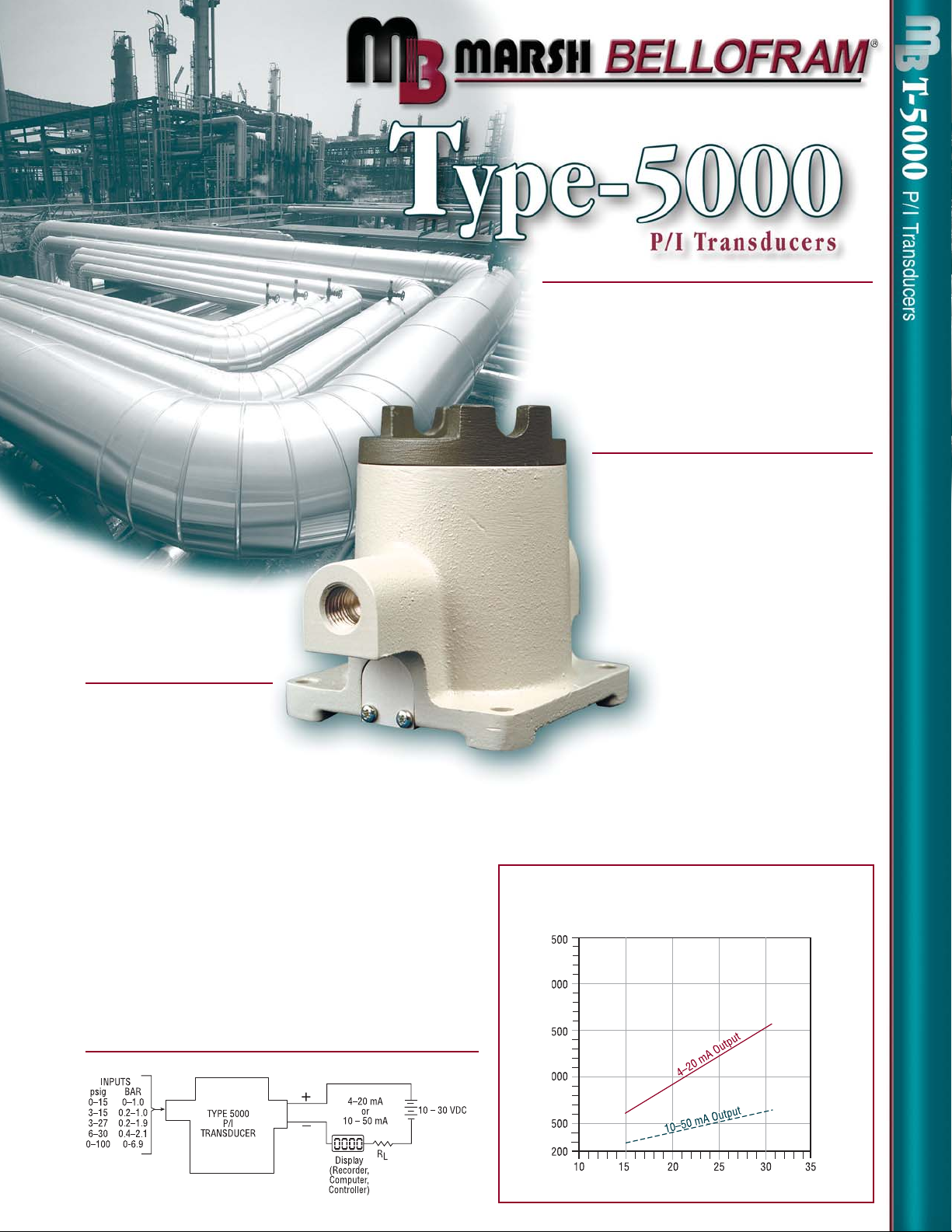
MAX LOAD RESISTANCE VS. SUPPLY VOLTAGE
4–20 mA Output: RI = 50 ohms / volt
10–50 mA Output: RI = 20 ohms / volt
Supply Voltage (vs) volts
Load Resistance (RI) ohms
FUNCTIONAL DIAGRAM
Page 2
IMPORTANT NOTICE
Our recommendations, if any, for the use of this product are based on tests
believed to be reliable. The greatest care is exercised in the selection of our
raw materials and in our manufacturing, no guarantee or warranty, express or
implied is made as to such use or effects incidental to such use, handling or
possession or the results to be obtained, whether in accordance with the
directions or claimed so to be. The manufacturer expressly disclaims responsibility therefor. Furthermore, nothing contained herein shall be construed as
a recommendation to use any product in conflict with existing laws and/or
patents covering any material use.
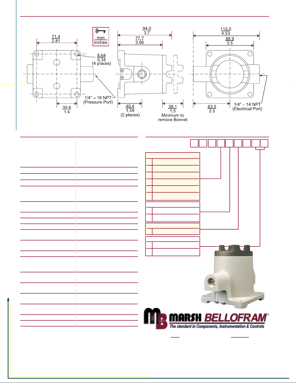
TYPE 5000 P/I TRANSDUCERS
DIMENSIONAL DRAWING
USA EUROPE
State Route 2, Box 305 9 Castle Park, Queens Drive
Newell, WV 26050 Nottingham NG2 1AH, UK
800- 727-5646 or (304)387-1200 Tel +44 (0) 115 993 3300
FAX (304) 387-4417 Fax +44 (0) 115 993 3301
info@marshbellofram.com bellofram@aol.com
www.marshbellofram.com
SPECIFICATIONS
Input signal 0–15 psig (0–1.0 BAR)
3–15 psig (0.2–1.0 BAR)
3–27 psig (0.2–1.9 BAR)
6–30 psig (0.4–2.1 BAR)
0.2–1.0 BAR (3–15 psig)
0–100 psig (0–6.9 BAR)
Output Signal 4–20 mA DC, 2 wire
10–50 mA DC, 2 wire
Output Protections Reverse polarity protected
Accuracy ± 0.1% span typical; ± 0.25% span max.
includes nonlinearity, hysteresis and
non-repeatability
Overpressure 45 psig (3.1 BAR) without calibration shift
60 psig (4.1 BAR) without failure
Allowable Loads See Graph
Response Time Less than 10 msec for step change to 99%R
Temperature Range-Operating -40º F to +180º F (-40º C to +82º C)
Temperature Effect Zero - Less than ± 0.01% R/ºF
Span - Less than ± 0.01% R/ºF
RFI Effect Less than 1% R at 10V/meter per
SAMA PMC 33.1, 2-abc
Power Supply 12–30 VDC
Power Supply Effect Less than 0.005% per volt change at the
input terminals within specified power
supply limits
Calibration Adjustments Multi-turn Zero and Span potentiometers with
± 25% min. adjustment
In-Process Output Monitoring Via test jacks within enclosure
without disturbing field wiring
Connections 1/4 – 18 NPT female pressure input,
1/2 – 14 NPT female electrical output
Mounting Suitable bracket or optional 1/4–20 U-bolt
pipe mounting kit
Finish Epoxy coated aluminum body and cover
Weight 1.7 lbs. (0.8 kg)
LT0775 5M 12/01
AGENCY APPROVAL
1X /P FM/CSA
INPUT
0 0–15 psig (0–1.0 BAR)
13–15 psig (0.2– 1.0 BAR)
2 3–27 psig (0.2–1.9 BAR)
3 6–30 psig (0.4–2.1 BAR)
4 0.2–1.0 BAR (3–15 psig)
5 0–100 psig (0–6.9 BAR)
OUTPUT
04 – 20 mA
1 10–50 mA
OPTIONS
00 None
01 Pipe Clamp Mounting Kit
ORDERING MATRIX
964 10
Sales & Application
800-727-5646
 Loading...