

Page 1
Page 2
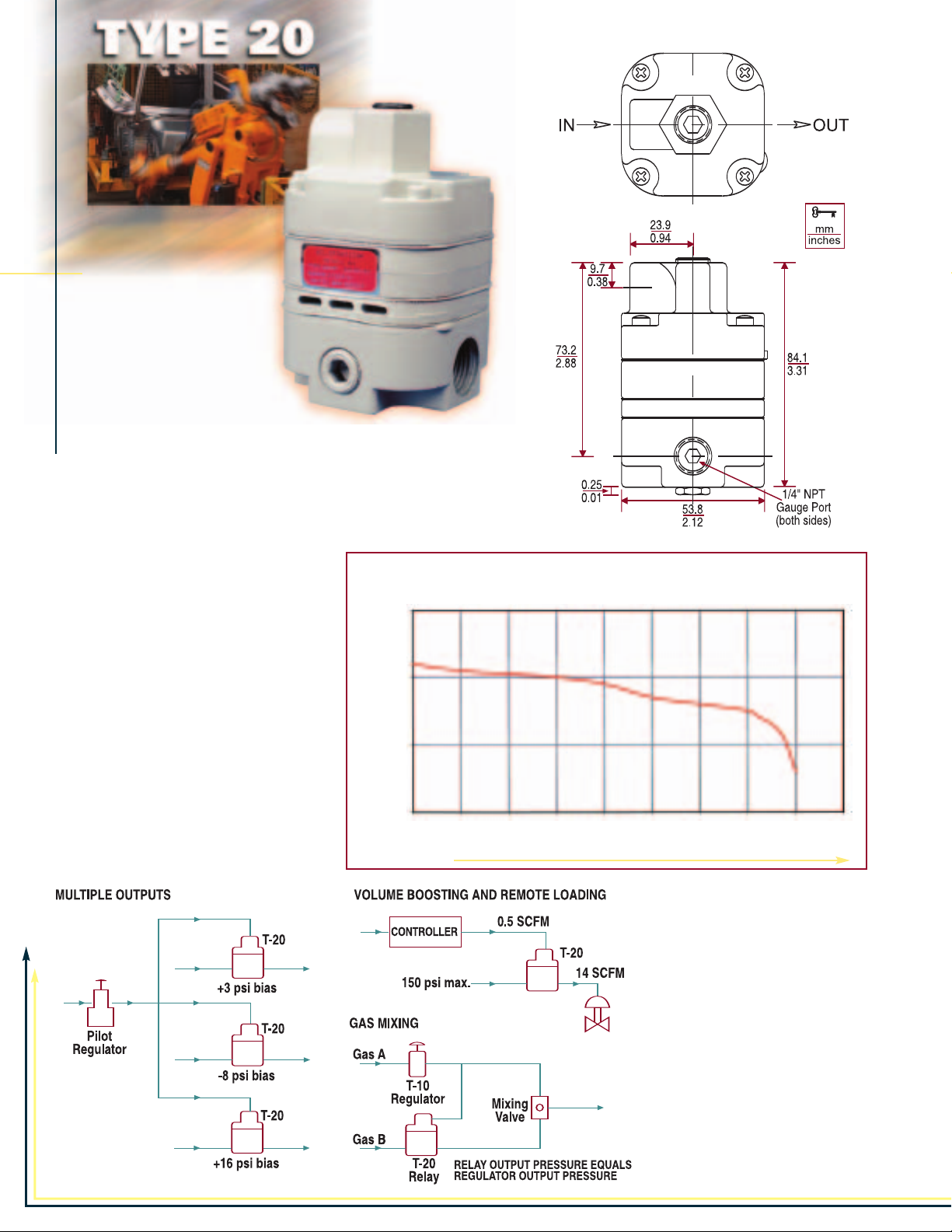
TYPE 20 PRECISION AIR RELAY
FEATURES
• Extreme accuracy
• Positive and negative
bias capability (±30 psig)
• Small size
• Rugged and stable
DESCRIPTION
The Type 20 Air Relay is a compact, two-stage, pilot operated 1:1 relay
with positive and negative bias adjustment capability. It accepts a signal
pressure and combined with the bias adjustment, maintains a resulting
output pressure with an accuracy and reliability unmatched by any other
pressure relay in its price range.
OUTPUT
MODELS
TYPE 20 - The basic relay is offered with a
choice of three port sizes.
TYPE 20HR & TYPE 20EXHR- High Relief
Relays - These relays provide extra fast
“blowdown” for very rapid release of output
pressure. The extra relief feature makes
this relay suitable for cylinder return stroke
actuation, air hoists, and similar applications requiring fast exhaust.
TYPE 20HF tions where the supply pressure is relatively low and a high flow rate is desired.
This relay is ideal for applica
PRESSURE
psig BAR
56 3.9
55 3.8
54 3.7
-
53 3.6
0.0
SCFM
LPM 0 60 115 170 225 280 340 400 450 510
FORWARD FLOW
Type 20, 20HR & 20EXHR
Flow Curve
@ 100 psig (6.9 BAR) Supply Pressure
10.0 12.0 14.0 16.0 18.0
2.0
4.0
6.0
8.0
APPLICATIONS
• Gate Actuators
•Air Hoists
Disc & Shoe Brakes
•
• Remote Positioning Devices
• Valve Rotors
• Control Valves
• Tensioning Systems
• Web Tracking Systems
Page 3
FEATURES
• Four adjustable positive bias ranges, from
0-10 psi (0-0.7 BAR) to 2-150 psi
(0.1-10.3 BAR)
• Flow capacity up to 50 SCFM
• Quick response to minute changes in
downstream pressure
• Dampening action of aspirator tube
maintains stable output pressure
• Output virtually unaffected by changes in
supply pressure
• Internal rolling diaphragm designed for millions of cycles
• Honking and buzzing eliminated by action of integral baffle and aspirator tube
• Can be disassembled and serviced without removing from line.
DESCRIPTION
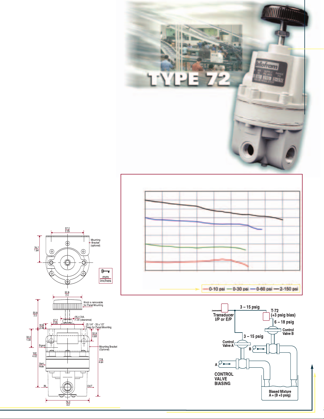
The Type 72 Relay features an adjustable bias pressure which enables users to obtain an output pressure which is the sum of a controlled input signal pressure plus the bias. The relay offers
an exceptionally high flow capacity (up to 50 SCFM/1400 LPM) with minimal pressure droop.
Output pressure is accurately maintained under varying flow conditions by means of an
aspirator tube, which adjusts the air supply valve opening in proportion to flow velocity.
A balanced supply valve utilizing a rolling diaphragm makes the relay virtually immune to changes
in supply pressure. Simple design makes
maintenance easy, and the relay can be
serviced without removing it from the line.
The standard signal-to-output ratio is 1:1,
but 1:2, 1:4 and 1:6 ratios are available on
special request. The Type 72HR is available
for applications that require extra fast “blowdown” for rapid release of output pressure.
OUTPUT
PRESSURE
psig BAR
90.0 6.2
80.0 5.5
70.0 4.8
60.0 4.1
50.0 3.4
40.0 2.8
30.0 2.1
20.0 1.4
0.7
10.0
00
SCFM 0.0 10.0 20.0 30.0 40.0 50.0 60.0 70.0 80.0 90.0
LPM
FORWARD FLOW
300
0
Type 72 Flow Curves
@ 100 psig (6.9 BAR) Supply Pressure
575
850
1150 1400 1700 2000 2550 2550
TYPE 72 POSITIVE BIAS BOOSTER RELAY
APPLICATIONS
The Type 72 Relay is used when high
flow capacity is required in conjunction with a positive output pressure
bias. Typical applications include:
• Gas Flow Control
• Tensioning Control
• Clutch & Brake Controls
oosting
B
olume
V
•
• Dancer Roll Loading
Calendar
•
Cylinder Bucking Control
•
• Valve Motor Loading
www.marshbellofram.com
Roll Loading
800-727-5646
•
Page 4

TYPE 20 TYPE 20 HR TYPE 20 EXHR TYPE 20 HF
Maximum 150 psig (10.3 BAR) 150 psig (10.3 BAR) 150 psig (10.3 BAR) 50 psig (3.4 BAR)
Supply Pressure
Sensitivity
Supply Pressure 0.005 psig 0.005 psig 0.005 psig 0.005 psig
Sensitivity (0.35 mBAR) (0.35 mBAR) (0.35 mBAR) (0.35 mBAR)
Flow Capacity 14 SCFM (400 LPM) 14 SCFM (400 LPM) 14 SCFM (400 LPM) 40 SCFM (1130 LPM)
Exhaust Capacity 2 SCFM (55 LPM) @ 10 SCFM (285 LPM) @ 15 SCFM (425 LPM) @ 2 SCFM (55 LPM) @
VOLUME BOOSTERS
Temperature Limits -20 to 160
Air Consumption 8 SCFH (4 LPM) 8 SCFH (4 LPM) 8 SCFH (4 LPM) 8 SCFH (4 LPM)
Port Size
Output Pressure 2-120 psig 2-120 psig 2-120 psig 2-50 psig
Range (0.1 – 8.3 BAR) (0.1 – 8.3 BAR) (0.1 – 8.3 BAR) (0.1 – 3.5 BAR)
Maximum Signal 120 psig (8.3 BAR) 120 psig (8.3 BAR) 120 psig (8.3 BAR) 50 psig (3.5 BAR)
1
⁄8" H
O (3.2mm)
2
per 25 psig per 25 psig per 25 psig per 25 psig
(1.7 BAR) change
in supply pressure in supply pressure in supply pressure in supply pressure
@ 20 psig (1.4 BAR) @ 20 psig (1.4 BAR) @ 20 psig (1.4 BAR) @ 20 psig (1.4 BAR)
signal and100 psig signal and 100 psig signal and 100 psig signal and 50 psig
(6.9 BAR) supply (6.9 BAR) supply (6.9 BAR) supply (3.5 BAR) supply
5 psig (0.35 BAR) 5 psig (0.35 BAR) 5 psig (0.35 BAR) 5 psig (0.35 BAR)
above a 20 psig above a 20 psig above a 20 psig above a 20 psig
(1.4 BAR) setpoint (1.4 BAR) setpoint (1.4 BAR) setpoint (1.4 BAR) setpoint
ºF -20 to 160ºF -20 to 160ºF -20 to 160ºF
(-29 to 71ºC) (-29 to 71ºC) (-29 to 71ºC) (-29 to 71ºC)
1
⁄8", 1⁄4", 3⁄8"
NPT, BSPP, BSPT NPT, BSPP, BSPT NPT, BSPP, BSPT NPT, BSPP, BSPT
1
⁄8" H
O (3.2mm)
2
1
⁄8" H
O (3.2mm)
2
1
⁄8" H
O (3.2mm)
2
(1.7 BAR) change (1.7 BAR) change (1.7 BAR) change
1
⁄8", 1⁄4", 3⁄8"
1
⁄8", 1⁄4", 3⁄8"
3
⁄8"
Weight 1.4 lb. (0.6 kg.) 1.4 lb. (0.6 kg.) 1.4 lb. (0.6 kg.) 1.4 lb. (0.6 kg.)
Ratio of Accuracy <0.5% <0.5% <0.5% <0.5%
for a 12 psig span
Page 5

TYPE 72 TYPE 72HR TYPE 75 TYPE 75 HR TYPE 79
250 psig (17.2 BAR) 250 psig (17.2 BAR) 250 psig (17.2 BAR) 250 psig (17.2 BAR) 400 psig (27.6 BAR)
1
⁄4" H
O (6.4mm)
2
1
⁄4" H
O (6.4mm)
2
1
⁄4" H
O (6.4mm)
2
1
⁄4" H
O (6.4mm) 1" H2O (25mm)
2
< 0.6 psig < 0.6 psig < 0.6 psig < 0.6 psig <0.35 psig
(0.01 BAR) (0.01 BAR) (0.04 BAR) (0.04 BAR) (0.02 BAR)
per 50 psig per 50 psig per 50 psig per 50 psig per 100 psig
(1.4 BAR) change
(1.4 BAR) change (3.5 BAR) change (3.5 BAR) change (6.9 BAR) change
in supply pressure in supply pressure in supply pressure in supply pressure in supply pressure
40 SCFM (1150 LPM) 40 SCFM (1150 LPM) 40 SCFM (1150 LPM) 40 SCFM (1150 LPM) >125 SCFM (3500 LPM)
@ 20 psig (1.4 BAR) @ 20 psig (1.4 BAR) @ 20 psig (1.4 BAR) @ 20 psig (1.4 BAR) @ 20 psig (1.4 BAR)
signal and 100 psig signal and 100 psig signal and 100 psig signal and 100 psig signal and 100 psig
(6.9 BAR) supply (6.9 BAR) supply (6.9 BAR) supply (6.9 BAR) supply (6.9 BAR) supply
6 SCFM (170 LPM) @ 15 SCFM (425 LPM) @ 6 SCFM (170 LPM) @ 15 SCFM (425 LPM) @ 31 SCFM (875 LPM) @
10 psig (0.69 BAR) 10 psig (0.69 BAR) 10 psig (0.69 BAR) 10 psig (0.69 BAR) 5 psig (0.35 BAR)
above a 20 psig above a 20 psig above a 20 psig above a 20 psig above a 20 psig
(1.4 BAR) setpoint (1.4 BAR) setpoint (1.4 BAR) setpoint (1.4 BAR) setpoint (1.4 BAR) setpoint
-40 to 200
ºF -40 to 200ºF -40 to 200ºF -40 to 200ºF -40 to 200ºF
(-40 to 93ºC) (-40 to 93ºC) (-40 to 93ºC) (-40 to 93ºC) (-40 to 93ºC)
<12 SCFH (5.7 LPM) <12 SCFH (5.7 LPM) <12 SCFH (5.7 LPM) <12 SCFH (5.7 LPM) <12 SCFH (5.7 LPM)
1
⁄4", 3⁄8", 1⁄2"
1
⁄4", 3⁄8", 1⁄2"
1
⁄4", 3⁄8" 1⁄2"
1
⁄4", 3⁄8", 1⁄2"
3
⁄8", 1⁄2", 3⁄4", 1"
NPT, BSPP, BSPT NPT, BSPP, BSPT NPT, BSPP, BSPT NPT, BSPP, BSPT NPT, BSPP, BSPT
0-150 psig 0-150 psig 0-150 psig 0-150 psig 0-200 psig
(0–10.3 BAR) (0–10.3 BAR) (0–10.3 BAR) (0–10.3 BAR) (0-13.8 BAR)
150 psig (10.3 BAR) 150 psig (10.3 BAR) 150 psig (10.3 BAR) 150 psig (10.3 BAR) 200 psig (13.8 BAR)
for 1:1 ratio for 1:1 ratio
1.75 lb. (0.8 kg.) 1.75 lb. (0.8 kg.) 1.3 lb. (0.6 kg.) 1.3 lb. (0.6 kg.) 4.5 lb. (2.0 kg.)
< 2% < 2% < 2% (1:1) < 2% (1:1) <1.5%
COMPARISON & SPECIFICATION
: Our recommendations, if any
NOTICE
ANT
T
IMPOR
The greatest care is exercised in the selection of our raw materials and in our manufacturing, no guarantee
reliable.
or warranty, express or implied is made as to such use or effects incidental to such use, handling or possession or
the results to be obtained, whether in accordance with the directions or claimed so to be.
ly disclaims responsibility therefor
to use any product in conflict with existing laws and/or patents covering any material use.
. Furthermore, nothing contained herein shall be construed as a recommendation
, for the use of this product are based on tests believed to be
The manufacturer express
www.marshbellofram.com •800-727-5646
-
Page 6

Transducer
Signal
Input
Supply Pressure
0-100 psig
Supply Pressure
100 psig
Relay Output
Transducer Ouput (3-15 psig)
Signal
Pressure
T-75
1:4
with
negative
bias
0-44 psig
T-1000
I/P or E/P
Transducer
TYPE 75 RELAYS
FEATURES
• Balanced valve design
• High flow capacity
•
Field serviceable
• Multiple output ratios
• Negative biasing option
DESCRIPTION
The Type 75 relay uses signal pressure to accurately control output pressure over a wide range of flow
and supply pressure variation.
Under varying flow conditions
output pressure is maintained by
use of an aspirator tube, which
adjusts the air supply valve opening in accordance with the flow
velocity. A balanced supply valve,
utilizing a rolling diaphragm,
makes the relay virtually immune
to changes in supply pressure.
Maintenance is simple due to
the unit construction, and the
relay can be serviced without
removing it from the line.
Signal to output pressure ratios
of 1:1, 1:2, 1:4 and 1:6 are available. Maximum output is 150
psig (10.3 BAR).
OUTPUT
PRESSURE
BAR
psig
25.0 1.7
20.0 1.4
1.0
15.0
10.0 0.7
5.0
0
SCFM 0.0 10 20 30 40 50
LPM 0 300 575 850 1150 1400
W
FOR
0.4
0
ARD FLOW
Type 75 Flow Curve
@ 100 psig (6.9 BAR) Supply Pressure (1/4” NPT)
APPLICATIONS
• Volume Boosting
• Dancer Roll Loading
• Calendar Roll Loading
• Cylinder Bucking Control
• Clutch and Brake Controls
• Gas Flow Control
• Tensioning Control
• Valve Motor Loading
MODELS
TYPE 75 - The basic relay offers excellent precision along
with high forward flow rates.
TYPE 75 HIGH RELIEF RELAYS - These relays provide
extra fast “blowdown” for very rapid release of output pressure. The extra relief feature makes this relay suitable for
cylinder return stroke actuation, air hoists, and similar applications requiring fast exhaust.
TYPE 75 NEGATIVE BIAS - The Type 75 Relay is also
available with a 4 ± 1 psig (0.3 ± 0.07 BAR) negative bias
spring mounted internally. (See cross-sectional drawing on
previous page.) This bias spring automatically subtracts
4 ± 1 psig (0.3 ± 0.07 BAR) from any signal pressure introduced. The relay then multiplies the net signal pressure by
its ratio value to obtain final output pressure.
This option is particularly useful in obtaining zero pressure
from pneumatic devices such as I/P transducers that
normally cannot be adjusted this low, as well as
obtaining higher outputs from such devices.
ype 75 Relay with
ypical applications of the
T
fixed negative bias include the electronic
control of the applications listed for the
ype 75 Relay
standard
T
To calculate relay output:
Relay output = (signal pressure) - 4 psi bias x
(relay ratio factor) where the relay ratio factor is
defined as follows:
Relay Ratio Factor
1:1
1:2 2
1:4 4
1:6 6
T
.
1
Page 7

FEATURES
• Balanced pintle
•
High flow capacity (200 + SCFM)
• Field serviceable
• Large port sizes available
• High exhaust capacity
• 200 psig output
DESCRIPTION
The Type 79 1:1 Ratio High Flow Precision Air Relay brings additional precision and control to the Bellofram line of precision control products.
The Type 79 relay is designed for applications where a precise control of flow
is needed. This regulator offers low droop, high accuracy and fine adjustment
sensitivity. The use of a Bellofram rolling diaphragm provides greater sensitivity and improved accuracy. The balanced pintle minimizes output pressure
changes caused by fluctuations in supply pressure.
Careful design and quality materials throughout assure long, trouble-free
operation. The rugged die-cast zinc and aluminum housings are pressure
tested to assure safe operation. The Type 79 is designed to withstand
harsh and abusive environments. This is attributed to a chemical conversion coating of all cast
components, and a vinyl paint finish.
The Type 79 can achieve flow rates of well over
200 SCFM (5600 LPM). This relay can be pipe or
bracket mounted.
OUTPUT
PRESSURE
psig BAR
90.0 6.2
80.0 5.5
70.0 4.8
60.0 4.1
50.0 3.4
Type 79 Flow Curve
@ 100 psig (6.9 BAR) Supply Pressure
Contact Bellofram Applications Engineering
for information on the VALVE-CONTROL
VERSION
utilizes soft exhaust seats to minimize air
consumption, increased deadband to
ignore small valve oscillations, and an integral bypass valve that can be ‘tuned’ for
optimum valve response.
of the Type 79. The Type 79V
TYPE 79 HIGH FLOW PRECISION AIR RELAY
40.0 2.8
2.1
30.0
1.4
20.0
0.7
10.0
00
SCFM 0 50 100 150 200 250 300
LPM 0 1400 2800 4250 5650 7100 8500
FORWARD FLOW
––3/8" ––1/2" ––3/4" ––1"NPT
APPLICATIONS
Clutch & Brake Controls
•
• Cylinder Bucking Control
• Dancer (Calendar) Roll Loading
Gas Flow Control
•
Tension Control
•
• Valve Motor Loading
• Volume Boosting
www.marshbellofram.com •800-727-5646
Page 8

Port Size Range Range Part
Type (NPT) psig BAR Number
Type 20 1/8" 2-120 0.1-8.3 961-004-000
Precision Relay 1/4" 2-120 0.1-8.3 961-005-000
1:1 Ratio 3/8" 2-120 0.1-8.3 961-006-000
Type 20HR Precision Relay 1/8" 2-120 0.1-8.3 961-001-000
High Relief Capacity 1/4" 2-120 0.1-8.3 961-002-000
1:1 Ratio 3/8" 2-120 0.1-8.3 961-003-000
Type 20 HF Precision Relay 3/8" 2-50 0.1-3.5 961-071-000
High Flow Capacity 1:1 Ratio
ype 20 EXHR 1/8" 2-120 0.1-8.3 961-009-000
T
1:1 Ratio 1/4" 2-120 0.1-8.3 961-010-000
3/8" 2-120 0.1-8.3 961-011-000
Type 72 1/4" 0-10 0-0.7 961-052-000
Positive Bias Booster Relay 1/4" 0-30 0-2.1 961-053-000
1:1 Ratio 1/4" 1-60 0.07-4.1 961-054-000
1/4" 2-150 0.1-10.3 961-055-000
3/8" 0-10 0-0.7 961-062-000
ORDERING INFORMATION
Type 72 HR (High Relief) 1/4" 0-10 0-0.7 961-178-000
Positive Bias Booster Relay 1/4" 0-30 0-2.1 961-179-000
1:1 Ratio 1/4" 1-60 0.07-4.1 961-180-000
Type 75 Precision Relay
1:1 Ratio 1/4" 0-150 0-10.3 961-058-000
1:1 Ratio 3/8" 0-150 0-10.3 961-066-000
1:2 Ratio 1/4" 0-150 0-10.3 961-059-000
1:2 Ratio 3/8" 0-150 0-10.3 961-067-000
1:4 Ratio 1/4" 0-150 0-10.3 961-060-000
1:4 Ratio 3/8" 0-150 0-10.3 961-068-000
1:6 Ratio 1/4" 0-150 0-10.3 961-045-000
1:6 Ratio 3/8" 0-150 0-10.3 961-069-000
Type 75 Precision Relay - Fixed Negative Bias (4psi)
1:1 Ratio 1/4" 0-150 0-10.3 961-090-000
1:1 Ratio 3/8" 0-150 0-10.3 961-091-000
1:2 Ratio 1/4" 0-150 0-10.3 961-092-000
1:2 Ratio 3/8" 0-150 0-10.3 961-093-000
1:4 Ratio 1/4" 0-150 0-10.3 961-094-000
1:4 Ratio 3/8" 0-150 0-10.3 961-095-000
1:6 Ratio 1/4" 0-150 0-10.3 961-096-000
1:6 Ratio
ype 75HR Precision Relay
T
1:1 Ratio
1:1 Ratio 3/8" 0-150 0-10.3 961-145-000
1:1 Ratio 1/2" 0-150 0-10.3 961-146-000
1:2 Ratio
1:2 Ratio
1:2 Ratio 1/2" 0-150 0-10.3 961-149-000
Type 75HR Precision Relay - Fixed Negative Bias (4psi)
1:1 Ratio
1:1 Ratio
1:1 Ratio 1/2" 0-150 0-10.3 961-152-000
1:2 Ratio 1/4" 0-150 0-10.3 961-153-000
1:2 Ratio 3/8" 0-150 0-10.3 961-154-000
1:2 Ratio 1/2" 0-150 0-10.3 961-155-000
Type 79 3/8" 0-200 0-13.8 961-156-000
High Flow Capacity 1/2" 0-200 0-13.8 961-157-000
1:1 Ratio 3/4" 0-200 0-13.8 961-158-000
3/8" 0-30 0-2.1 961-063-000
3/8" 1-60 0.07-4.1 961-064-000
3/8" 2-150 0.1-10.3 961-065-000
1/4" 2-150 0.1-10.3 961-181-000
3/8" 0-10 0-0.7 961-182-000
3/8" 0-30 0-2.1 961-183-000
3/8" 1-60 0.07-4.1 961-184-000
3/8" 2-150 0.1-10.3 961-185-000
3/8"
1/4" 0-150 0-10.3 961-144-000
1/4"
3/8"
1/4"
3/8"
1" 0-200 0-13.8 961-159-000
0-150
0-150
0-150
0-150
0-150
0-10.3
0-10.3 961-147-000
0-10.3 961-148-000
0-10.3
0-10.3
961-097-000
961-150-000
961-151-000
For options and accessories, replace the last
three zeros in the relay part number with
three digits from the following tables:
Type 20
Option 8
8. Pressure Gauge 008
Type 72
Option 3 5 7 8 9
3. Kno b (standard)
Square Head 003 053 073 083
5. Epoxy Finish 005 075 085 095
7. Mounting Bracket 007 087 097
8. Pressure Gauge 008 098
9. Tamper Resistant Cover 009
Type 75
Option 5 7 8
5. Epoxy Finish 005 075 085
7. Mounting Bracket 007 087
8. Pressure Gauge 008
Type 79
Option 1 2 5 6 7
1. Low Bleed 001 051 061 071
2. Non-Relieving 002 052 062 072
5. Epoxy Finish 005 065 075
6. Tapped Vent 006 076
7. Tapped Supply Port 007
Pressure Gauge: Dual scale (English &
Metric) 2-inch (50.8 mm) gauges are available
Epoxy finish: Gray epoxy coating for greater
corrosion resistance.
Mounting Bracket: Zinc-plated steel bracket
for side mounting. (For T-79 order p/n 607-293-000)
Tamper Resistant Cover: A cover placed
over the adjusting screw to prevent ordinary
hand adjustments.
Low Bleed: Reduces steady-state air consumption by approximately 50%.
Non-Relieving: Used in applications where it
is desirable to relieve pressure downstream
of the relay
. Non-relieving relays should not be
used for low or no flow applications.
apped V
T
ent (Exhaust):
1/4" NPT
tapped port
to allow for installation of plumbing to capture
exhaust air.
Tapped Supply Gauge Port: 1/4" NPT
tapped port is offered as a pressure tap for
monitoring the inlet or upstream pressure
supplied to the regulator. (T-79 only)
BSPP
or BSPT
Threads can be ordered by adding ‘BSPP’
:
British Standard Pipe
or
‘BSPT’ to the end of the part number.
T0961 3m 4/04
L
info@marshbellofram.com
USA •
EUROPE
bellofram@aol.com
•
State Route 2, Box 305 9 Castle Park, Queens Drive
Newell, WV 26050 Nottingham NG2 1AH, UK
el +44 (0) 115 993 3300 • Fax +44 (0) 115 993 3301
(304) 387-1200 • F
AX (304) 387-4417
T
www.marshbellofram.com •800-727-5646
 Loading...