

Page 1
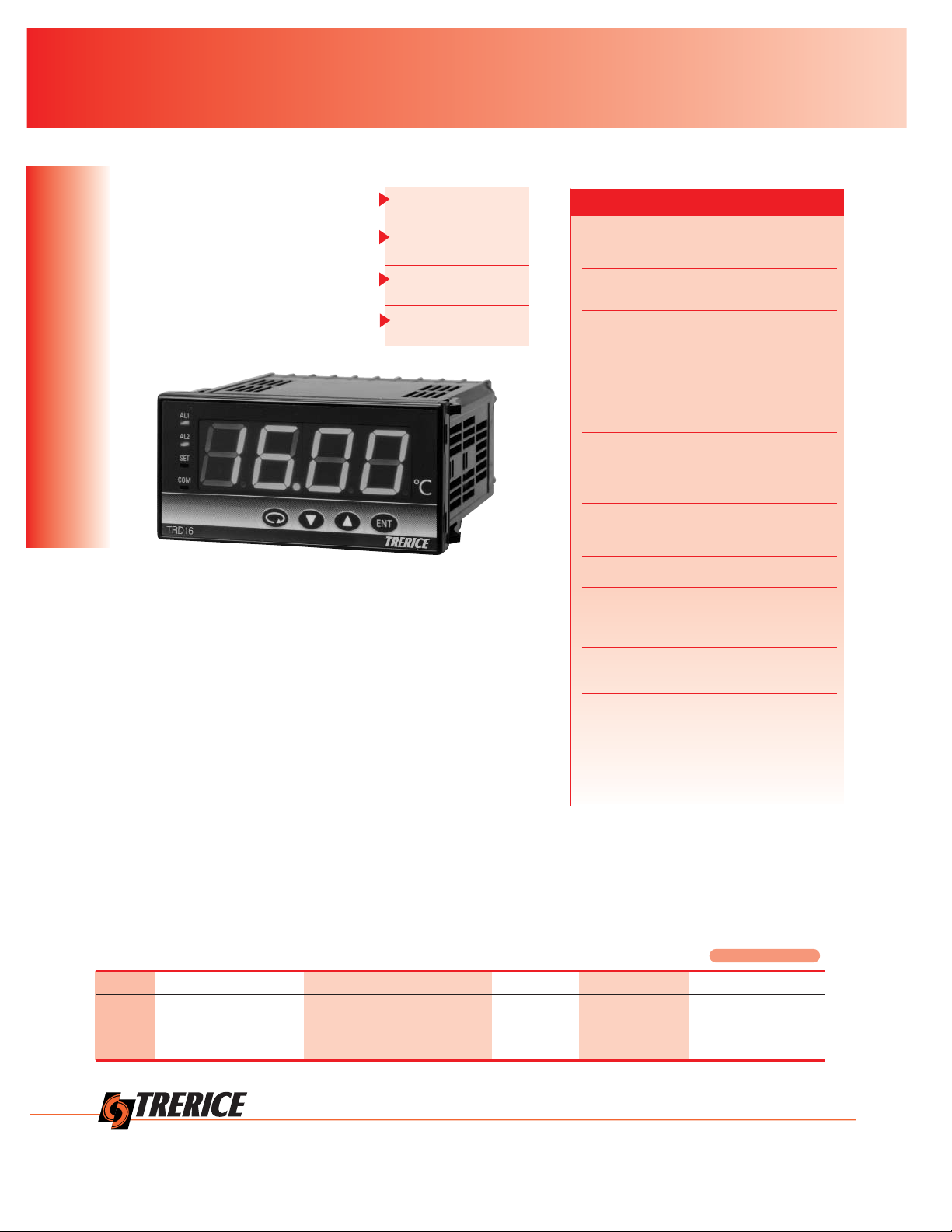
The Trerice TRD16 Digital Indicator
is a superb choice when remote digital
indication is required. The 2 times
per second sampling cycle provides
accurate, reliable monitoring, and the
large LED display provides easy
readability. The TRD16 can be used
with any Trerice RTD or Thermocouple.
Size is 96 mm x 48 mm (
1
/8 DIN).
Digital Temperature Indicator TRD16
Specifications
ELECTRONIC TEMPERA TURE SENSORS
Model
TRD16
Display 4 digit, 20 mm red LED
Sampling Cycle: 2x/second
Input Multi (switchable between)
Thermocouple:
B, R, S, K, E, J, T, N;
or RTD: Platinum, 100Ω, 3-wire
Voltage (mV, V): 0-10 mVDC,
0-5 VDC, 0-10 VDC, 1-5 VDC
Current: 4-20 mA
Power Requirements
Supply Voltage:
100-240 VAC/50/60 Hz,
24 VAC/VDC (option)
Consumption:
11 VA (AC) Max
7 W (DC) Max
Accuracy ±0.3% + 1 digit of measuring range
Ambient Temperature
Maximum: 122°F (50°C)
Minimum: 14°F (-10°C)
Humidity Maximum: 90% RH
Non-condensing
Approximate Shipping Weight
0.6 lbs [0.27 kg]
HOW TO ORDER Sample Order Number: TRD16 8 90 0 4 0
Model Input Power Supply Alarm Analog Output Communication Function
TRD16 8 Multi (T/C, RTD mV, V) 90 100-240 VAC 50/60 Hz 0 None 0 None 0 None
4 mA 08 24 VAC or 24 VDC 50/60 Hz 1 High/Low 3 0 to 10 mVDC 5 RS485
4 4 to 20 mA 7 RS232C
6 0 to 10 VDC
96 mm x 48 mm
(1/8 DIN)
Multi-inputs
and Multi-Ranges
Large 20mm
Red LED Display
2 Times per Second
Sampling Code
The TRD16 Digital Indicator
is specifically designed to
interface with the TRS16
Selector Switch by means of
an included snap bracket.
12950 W. Eight Mile Road • Oak Park, MI 48237-3288 • TEL:248/399-8000 • FAX: 248/399-7246 • www.TRERICE.com
146
Page 2
Digital Temperature Indicator TRD16
ELECTRONIC TEMPERA TURE SENSORS
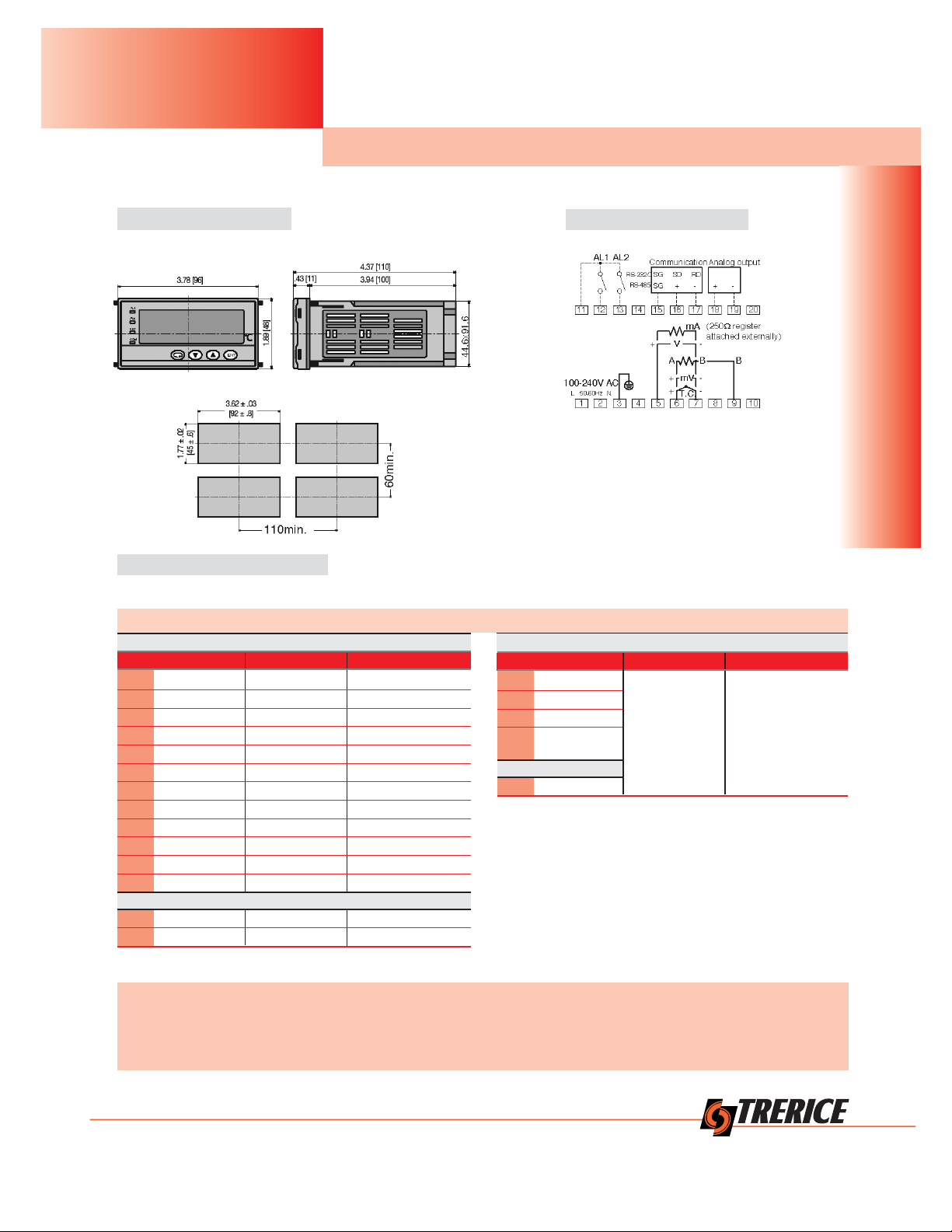
EXTERNAL DIMENSIONS
PANEL CUTOUT DIMENSIONS
TERMINAL ARRANGEMENT
WARNING: The TRD16 Indicator is designed for the control of temperature, humidity and other physical values of general industrial
equipment. (It is not to be used for any purpose which regulates the prevention of serious effects on human life or safety.)
CAUTION: If the possibility of loss or damage to your system or property as a result of failure of any part of the process exists, proper
safety measures must be made before the instrument is put into use so as to prevent the occurrence of trouble.
Initial value:
0.0~100.0
Scaling
setting range:
-1999~9999
Span:
10~5000 counts
Thermocouple
B, R, S, K, E, J, T, N:
JIS/ANSI/IEC
*1 Thermocouple U, L:
DIN 43710
*2 Thermocouple
WRe5-26:
Made of Hoskins
Input and Range Codes are not required for ordering, but are used for field programming.
Thermocouple Input
Code Type Range (°C) Range (°F)
01 B 0 ~1800 0 ~ 3300
02 R 0 ~1700 0 ~ 3100
03 S 0 ~1700 0 ~ 3100
04 K -199.9 ~ 800.0 -300 ~ 1500
05 K 0 ~1200 0 ~ 2200
06 E 0 ~ 700 0 ~ 1300
07 J 0 ~ 600 0 ~ 1100
08 T -199.9 ~ 300.0 -300 ~ 600
09 N 0 ~1300 0 ~ 2300
10 *1 U -199.9 ~ 300.0 -300 ~ 600
11 *1 L 0 ~ 600 0 ~ 1100
12 *2 WRe5-26 0 ~ 2300 0 ~ 4200
RTD Input
31 Pt100Ω -200 ~ 600 -300 ~ 1100
32 Pt100Ω -100.0 ~ 100.0 -150.0 ~ 200.0
Voltage Input
Code Type Range (°C) Range (°F)
71 0~10mV
81 0~ 5V
82 1~ 5V
83 0~10V
Current Input
95 4~20mA*
*Uses supplied shunt resistor.
Programmable Inputs and Ranges
All dimensions are nominal.
Dimensions in [ ] are in millimeters.
147
12950 W. Eight Mile Road • Oak Park, MI 48237-3288 • TEL:248/399-8000 • FAX: 248/399-7246 • www.TRERICE.com
RTD
 Loading...