

Page 1
Control Valves
VALVES
CONTROL
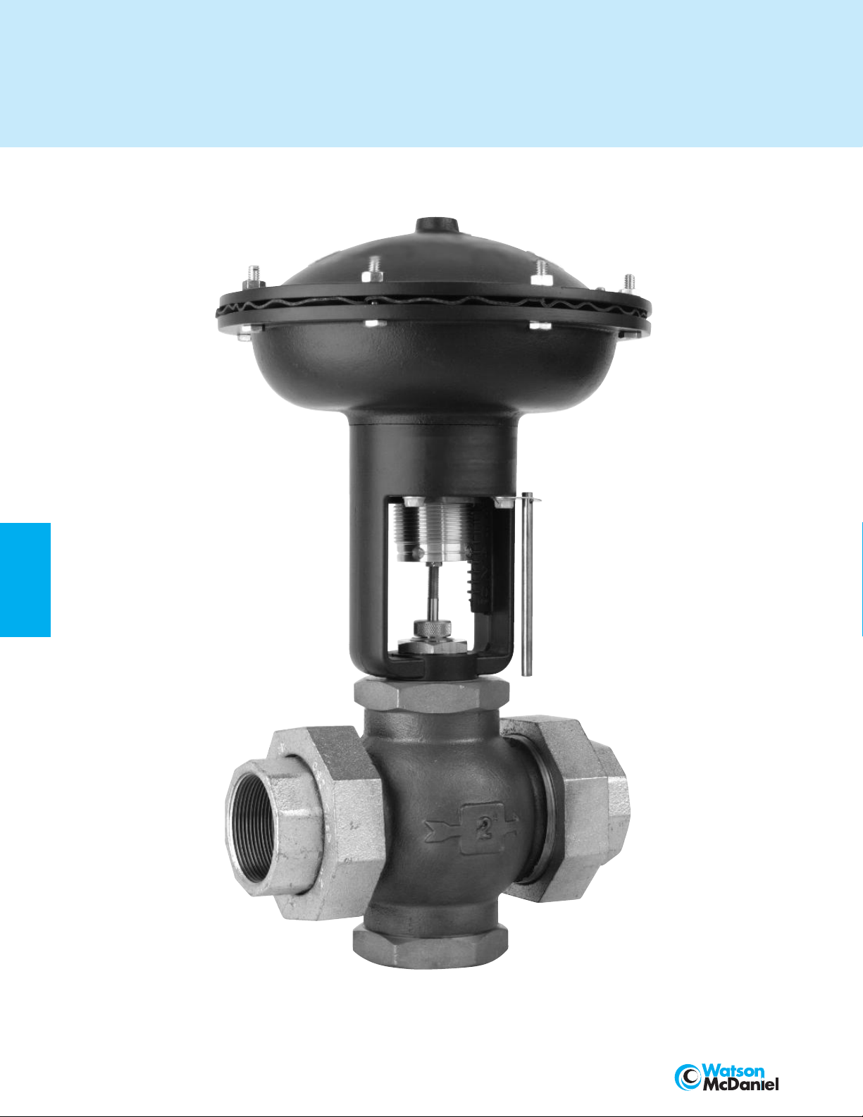
W910 COMPACT
CONTROL VALVE
184
428 Jones Boulevard • Limerick Airport Business Center • Pottstown PA • 19464 • Tel: 610-495-5131 • Fax: 610-495-5134
www.watsonmcdaniel.com
Page 2
Control Valves
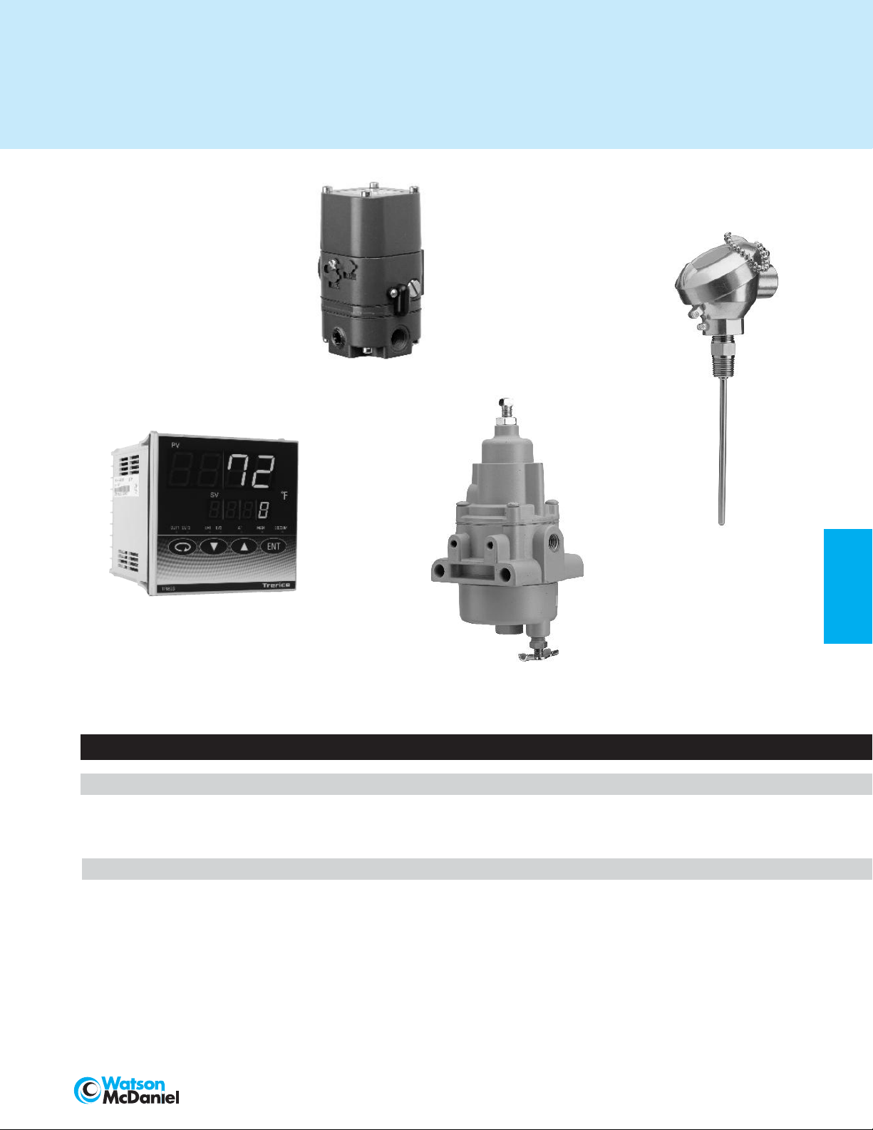
TA901
I/P TRANSDUCER
ELECTRONIC
TEMPERATURE
SENSOR
RTD or THERMOCOUPLE
TR890
ELECTRONIC
PID CONTROLLER
TA987
AIR FILTER/REGULATOR
Control Valves
W910 Series Compact Control Valve 186-196
The W910 Series Pneumatic Control Valve offers high quality at an economical price,
incorporating many features found only on more expensive units. Models are available
to provide the proper flow response required by the application.
Controllers & Sensors 197-205
Understanding a Control Loop 197
Controllers – Design & Operation 198-199
TR890 Series Electronic PID Controller 200-201
TA901 Series Electropneumatic I/P Transducer 202
TA987 Air Filter/ Regulator (for TA901 Pneumatic Control Device) 203
Electronic Temperature Sensors (RTD or Thermocouple) 204
Thermowells (for Temperature Sensors) 205
Page No.
CONTROL
VALVES
428 Jones Boulevard • Limerick Airport Business Center
www.watsonmcdaniel.com
• Pottstown PA • 19464 • Tel: 610-495-5131 • Fax: 610-495-5134
185
Page 3
CONTROL VALVES
W910 Series
Compact Control Valve
Watson McDaniel reserves the
right to change the designs
and/or materials of its
products without notice.
©2010 Watson McDaniel Company
Models
Service
Sizes 1/2”, 3/4”, 1”, 11/4”, 11/2”, 2”,
Connections Union Ends, 125# Flanged
Body Material 1/2” – 2” Bronze
Seat Material Stainless Steel
Max. Inlet Pressure
DESIGN PRESSURE/TEMPERATURE RATING – PMA/TMA
Union Ends 250 PSIG @ 450˚ F
125# FLG 125 PSIG @ 450˚ F
Description
CONTROL
degrees between minimal flow and full capacity in response to a
signal from an external control device. The control valve, often
referred to as “the final control element,” is a critical part of any
control loop, as it performs the physical work and is the element
that directly affects the process.
A control valve is a device capable of modulating flow at varying
VALVES
Principles of Operation
A control valve is comprised of an actuator mounted to a valve.
The valve modulates flow through movement of a valve plug in
relation to the port(s) located within the valve body. The valve plug
is attached to a valve stem, which, in turn, is connected to the
actuator. The actuator, which can be pneumatically or electrically
operated, directs the movement of the stem as dictated by the
external control device.
Pneumatic/Diaphragm Actuated
Watson McDaniel Pneumatic Actuators are direct acting and
utilize an air signal from an external control device to create a
modulating control action. The force of the air signal is received
into the actuator through a top port and distributed across the full
area of the actuator’s diaphragm. The diaphragm presses down on
the diaphragm plate and spring return assembly, which then moves
the valve stem and plug assembly downward to stroke the valve.
This actuator will move to a stem-out position in the event of air
signal failure. The choice of valve action (stem-In-To-Close or
stem-In-To-Open) will determine its signal failure position.
W910A, W910B, W910C, W910TB,
W910EPA, W910EPC
Water, Steam, Other Liquids
21/2”, 3”, 4”
250# Flanged (optional)
21/2” – 4” Cast Iron
250 PSIG
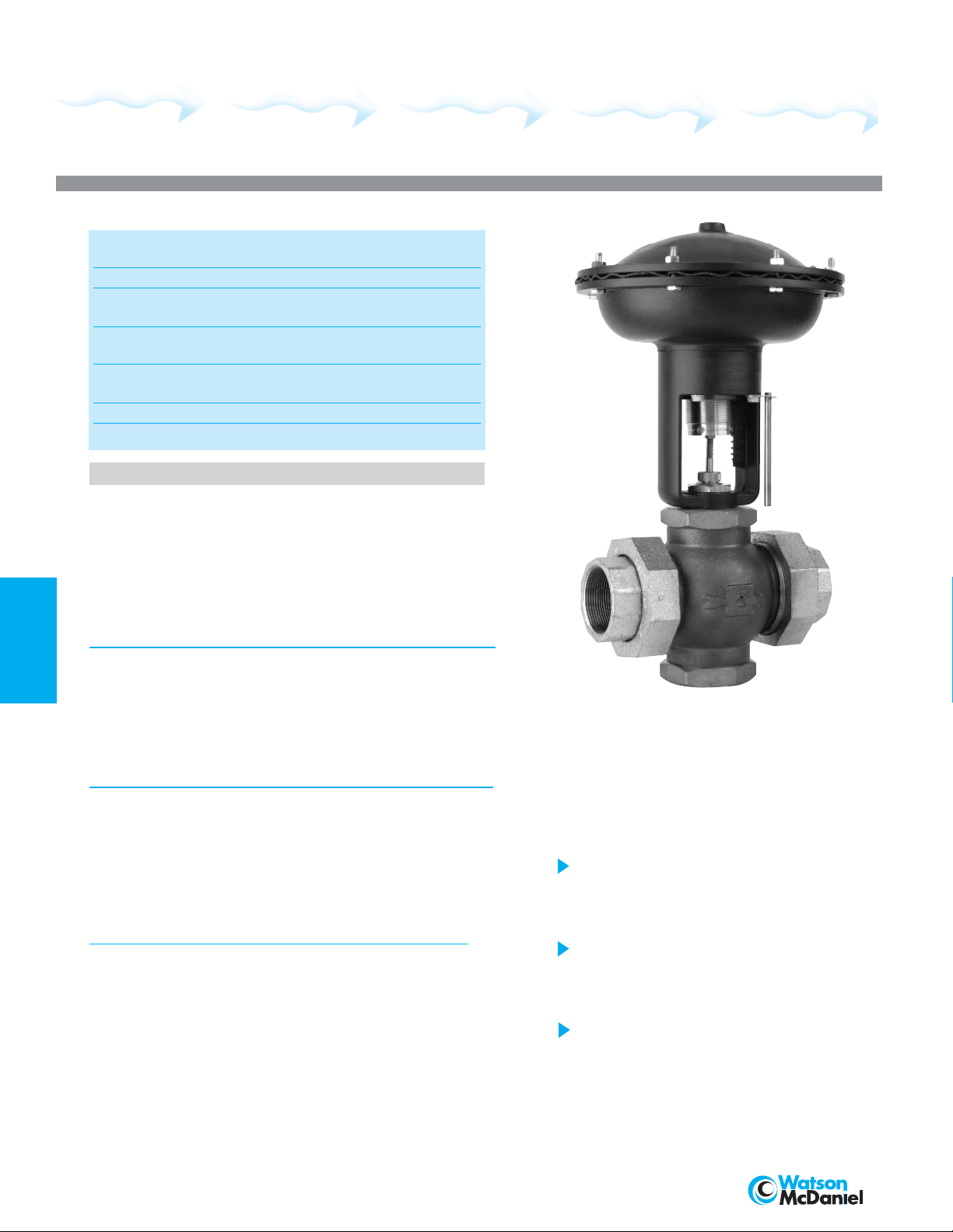
The W910 Series Pneumatic Control Valve
ers high quality at an economical price,
off
incorporating many features found only on
more expensive units. The following Models are
available to provide the proper flow response
required by the application:
The W910A, W910B & W910C are used
for On/Off control applications, providing a
quick-opening flow response when used
with single or double seated valves.
The W910TB is used for proportional or
PID control applications, providing a throttling
flow response when used with double seated
or 3-way valves.
The W910EPA & W910EPC are used for
proportional or PID control applications,
providing equal percentage flow response
when used with single seated valves.
186
428 Jones Boulevard • Limerick Airport Business Center • Pottstown PA • 19464 • Tel: 610-495-5131 • Fax: 610-495-5134
www.watsonmcdaniel.com
Page 4
CONTROL VALVES
W910 Series
Compact Control Valve
Specifications
Actuator
Model Size Action Signal
W910A 7" On/Off 15 PSIG
W910B 10" On/Off 15 PSIG
W910C 12" On/Off 15 PSIG
W910TB 10" Throttling* 3-15 PSIG
W910EPA 7" Equal
W910EPC 12" Equal
* Includes 3-Way Valves
Actuator Housing
Setting Scale
Adjustment Screw
Adjustment Screw Bushing
Range Adjustment Spring
Pressure Plate
Diaphragm
Air Pressure to Diaphragm
Air Pressure Connection
Operating Temperature
Diaphragm
Die cast aluminum, epoxy powder
coated blue finish.
Integral to housing
Brass
Lubricant impregnated sintered bronze
Cadmium plated
Aluminum
Nylon reinforced EDPM
30 PSIG maximum
1
/8“ NPT Female
Ambient:
-40°F (-40°C) to 180°F (82°C)
Process Flow:
-40°F (-40°C) to 410°F (210°C)
Control Input
Percentage 3-15 PSIG
Percentage 3-15 PSIG
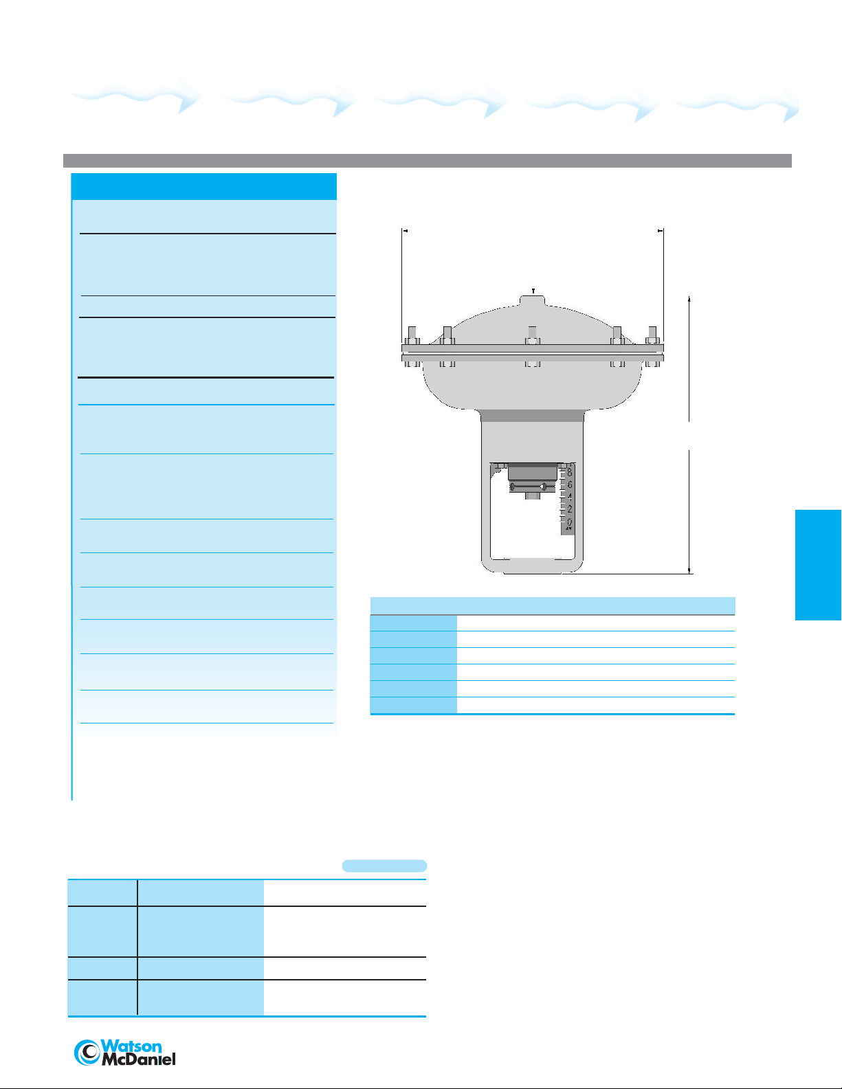
Units: inches [mm]
A
AIR INLET
1/8” NPT
B
Actuator Number A B Approx. Shipping Weight
W910A 7.0 [178] 9.8 [249] 6.6 lbs [2.97 kg]
W910B 9.3 [236] 9.8 [249] 8.5 lbs [3.83 kg]
W910C 11.4 [290] 9.8 [249] 12.0 lbs [5.41 kg]
W910TB 9.3 [236] 9.8 [249] 9.6 lbs [4.32 kg]
W910EPA 7.0 [178] 9.8 [249] 7.6 lbs [3.42 kg]
W910EPC 11.4 [290] 9.8 [249] 13.1 lbs [5.90 kg]
Actuator
• W910 Series Pneumatic Actuators are used in conjunction with
the W910 Series Control Valve. Choose the appropriate Actuator
model based on the intended service.
CONTROL
VALVES
HOW TO ORDER Sample Order Number: W910TB - A56
Actuator
Model
W910A
W910B On/Off Refer to pages 188-190
W910C
W910TB Throttling Refer to pages 191-193
W910EPA
W910EPC
Control Action Valve Body Number
Equal Percentage Refer to page 188
428 Jones Boulevard • Limerick Airport Business Center • Pottstown PA • 19464 • Tel: 610-495-5131 • Fax: 610-495-5134
www.watsonmcdaniel.com
Procedure:
1. Determine the Actuator Model ( W910A, W910B, W910C,
W910TB, W910EPA or W910EPC) required.
Note: Refer to the maximum close-off pressur
the Valve Body Selection tables to deter
equired by your application.
r
2. Determine the
Size, style and material required by the application.
Note: Consult the Valve Selection tables on the following
pages to determine the required Valve Body Number.
Valve Body Number based on the Valve
e columns in
mine the Actuator size
187
Page 5
CONTROL VALVES
W910 Series
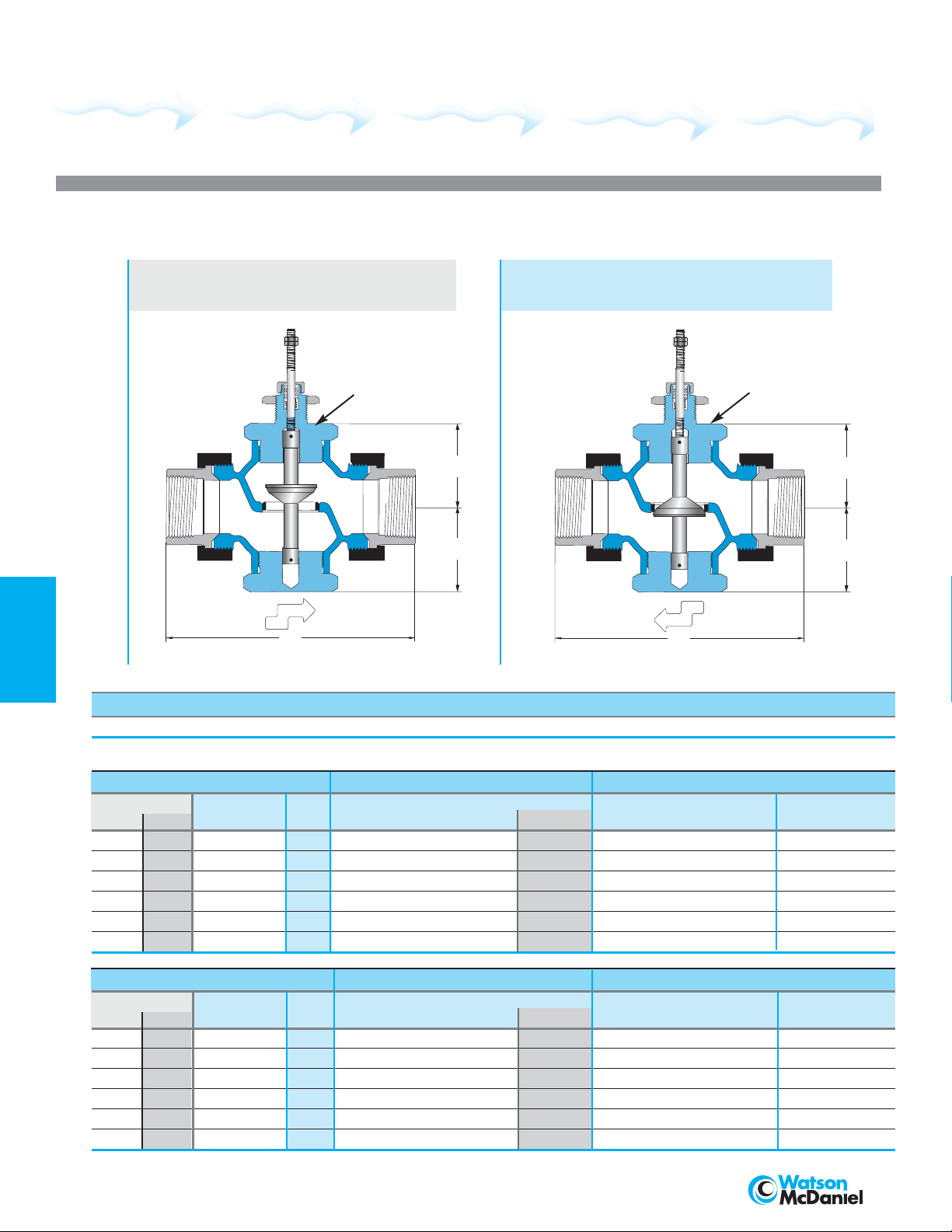
Valve Body for W910A, W910B, W910C, W910EPA & W910EPC
Single Seat • 1/2” – 2”
Stem In-To-Close
(normally closed)
VALVES
CONTROL
Specifications
Body Material Trim Material Trim Style Connection Pressure & Temperature Rating
Bronze Stainless Steel ML or EP NPT with Malleable Iron Union Ends 250 PSI @ 410°F (210°C)
Valve Body Selection
In-To-Close (Normally Open)
(normally open)
Actuator
Mounting
Surface
C
C
B
B
FLOW
A
A
Maximum Close-Off Pressure (PSI ΔP)
Valve Body No. Size Actuator Dimensions Approximate
ML EP
A14 E14
A19 E19
A26 E26 1" 8.4 200 250 x 200 6.0 [152] 2.3 [58] 2.3 [58] 6.0 lbs [2.70 kg]
A36 E36 11/4" 15 100 250 x 150 7.2 [183] 2.6 [66] 2.6 [66] 9.7 lbs [4.37 kg]
A47 E47 11/2" 21 50 150 250 100 7.7 [196] 2.6 [66] 2.6 [66] 10.8 lbs [4.86 kg]
A58 E58 2" 33 25 50 250 50 8.6 [218] 3.1 [79] 3.1 [79] 16.3 lbs [7.34 kg]
Connection (NPT)
1
/2" 2.8 250 x x 250 4.8 [122] 1.8 [46] 1.8 [46] 3.0 lbs [1.35 kg]
3
/4" 5.6 250 x x 250 5.6 [142] 2.3 [58] 2.3 [58] 4.9 lbs [2.21 kg]
C
W910A W910B W910C W910EPC A B C Shipping Wt.
v
BRONZE
Stem In-To-Open
FLOW
A
A
ML = Modified Linear (On/Off); EP = Equal Percentage
Actuator
Mounting
Surface
C
C
B
B
188
In-To-Open (Normally Closed)
alve Body No.
V
ML EP
A15 E15
A22 E22
A30 E30 1" 8.4 200 x x 200 6.0 [152] 2.3 [58] 2.3 [58] 6.0 lbs [2.70 kg]
A41 E41 11/4" 15 150 x x 150 7.2 [183] 2.6 [66] 2.6 [66] 9.7 lbs [4.37 kg]
A52 E52 11/2" 21 100 x x 100 7.7 [196] 2.6 [66] 2.6 [66] 10.8 lbs [4.86 kg]
A63 E63 2" 33 50 x x 50 8.6 [218] 3.1 [79] 3.1 [79] 16.3 lbs [7.34 kg]
All dimensions are inches [mm].
428 Jones Boulevard • Limerick Airport Business Center • Pottstown PA
Size Actuator
Connection (NPT)
1
/2"
3
/4" 5.6
C
v
2.8 250 x x 250 4.8 [122] 1.8 [46] 1.8 [46] 3.0 lbs [1.35 kg]
Maximum Close-Off Pressure (PSI ΔP)
Dimensions Approximate
W910A
250 x x 250 5.6 [142] 2.3 [58] 2.3 [58] 4.9 lbs [2.21 kg]
W910B W910C W910EPA A B C Shipping Wt.
• 19464 • Tel: 610-495-5131 • Fax: 610-495-5134
www.watsonmcdaniel.com
Page 6
CONTROL VALVES
W910 Series
BRONZE
Stem In-To-Close
(normally open)
Valve Body for W910A,W910B & W910C
Double Seat • 3/4” – 2”
Stem In-To-Open
(normally closed)
Actuator
Mounting
Surface
C
C
B
B
FLOW
A
A
FLOW
A
A
Actuator
Mounting
Surface
C
C
B
B
CONTROL
VALVES
Specifications
Body Material Trim Material Trim Style Connection Pressure & Temperature Rating
Bronze Stainless Steel Modified Linear NPT with Malleable Iron Union Ends 250 PSI @ 410°F (210°C)
Valve Body Selection
In-To-Close (Normally Open)
Valve Body
Number
A21
A29 1" 1" 12 250 x x 6.0 [152] 2.3 [58] 2.3 [58] 6.1 lbs [2.75 kg]
A39 11/4"1
A50 11/2"1
A61 2" 2" 47 200 x x 8.6 [218] 3.1 [79] 3.1 [79] 17.0 lbs [7.65 kg]
In-To-Open (Normally Closed)
Valve Body
Number
A24
A33 1" 1" 12 250 x x 6.0 [152] 2.3 [58] 2.3 [58] 6.1 lbs [2.75 kg]
A44 11/4"1
A55 11/2"1
A66 2" 2" 47 200 x x 8.6 [218] 3.1 [79] 3.1 [79] 17.0 lbs [7.65 kg]
All dimensions are inches [mm].
Connection (NPT) Nominal Port
Connection (NPT) Nominal Port
Size Actuator Dimensions Approximate
3
/4"
3
/4"
3
/4" 8 250 x x 5.6 [142] 2.3 [58] 2.3 [58] 5.0 lbs [2.25 kg]
1
/4" 21 250 x x 7.2 [183] 2.6 [66] 2.6 [66] 10.1 lbs [4.55 kg]
1
/2" 30 250 x x 7.7 [196]
Size Actuator Dimensions Approximate
3
/4" 8 250 x x 5.6 [142] 2.3 [58] 2.3 [58] 5.0 lbs [2.25 kg]
1
/4" 21 250 x x 7.2 [183] 2.6 [66] 2.6 [66] 10.1 lbs [4.55 kg]
1
/2" 30 250 x x 7.7 [196] 2.6 [66] 2.6 [66] 11.1 lbs [5.00 kg]
Maximum Close-Off Pressure (PSI ΔP)
C
W910A W910B W910C A B C Shipping Wt.
v
2.6 [66] 2.6 [66] 11.1 lbs [5.00 kg]
Maximum Close-Off Pressure
C
W910A W910B W910C A B C Shipping Wt.
v
(PSI ΔP)
428 Jones Boulevard • Limerick Airport Business Center • Pottstown PA • 19464 • Tel: 610-495-5131 • Fax: 610-495-5134
www.watsonmcdaniel.com
189
Page 7
CONTROL VALVES
W910 Series
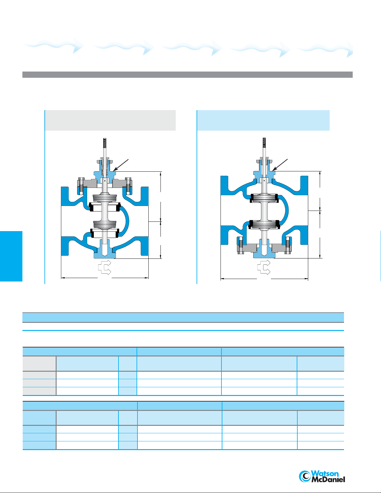
Valve Body for W910A, W910B & W910C
Double Seat • 21/2”–4”
Stem In-To-Close
(normally open)
Actuator
Mounting
Surface
C
C
B
B
Stem In-To-Open
(normally closed)
CAST IRON
Actuator
Mounting
Surface
C
C
B
B
VALVES
CONTROL
FLOW
A
FLOW
A
A
Specifications
Body Material Trim Material Trim Style Connection Pressure & Temperature Rating
Cast Iron Stainless Steel Modified Linear 125# Flanged 125 PSI @ 350°F (176°C)
Valve Body Selection
In-To-Close (Normally Open)
Valve Body
Number
B73 21/2"2
B78 3"
B83 4" 4" 196 125 x x 11.4 [290] 6.3 [160] 6.5 [165] 100 lbs [45 kg]
In-To-Open (Normally Closed)
Valve Body
Number
B74 21/2"2
B79 3" 3" 90 125 x x 9.0 [229] 5.0 [127] 5.6 [142] 70 lbs [32 kg]
B84 4" 4" 196 125 x x 11.4 [290] 6.3 [160] 6.5 [165] 100 lbs [45 kg]
All dimensions are inches [mm].
Connection Nominal PortC
Connection Nominal Port
Size Actuator Dimensions Approximate
1
/2" 69 125 x x 7.8 [198] 4.8 [122] 5.4 [137] 45 lbs [20 kg]
3" 90 125 x x 9.0 [229] 5.0 [127] 5.6 [142] 70 lbs [32 kg]
Size Actuator
1
/2" 69 125 x x 7.8 [198] 4.8 [122] 5.4 [137] 45 lbs [20 kg]
Maximum Close-Off Pressure (PSI ΔP)
W910A W910B
v
Maximum Close-Off Pressure (PSI ΔP)
C
W910A W910B W910C A B C Shipping Wt.
v
W910C A B C Shipping Wt.
Dimensions Approximate
190
428 Jones Boulevard • Limerick Airport Business Center • Pottstown PA • 19464 • Tel: 610-495-5131 • Fax: 610-495-5134
www.watsonmcdaniel.com
Page 8

CONTROL VALVES
W910 Series
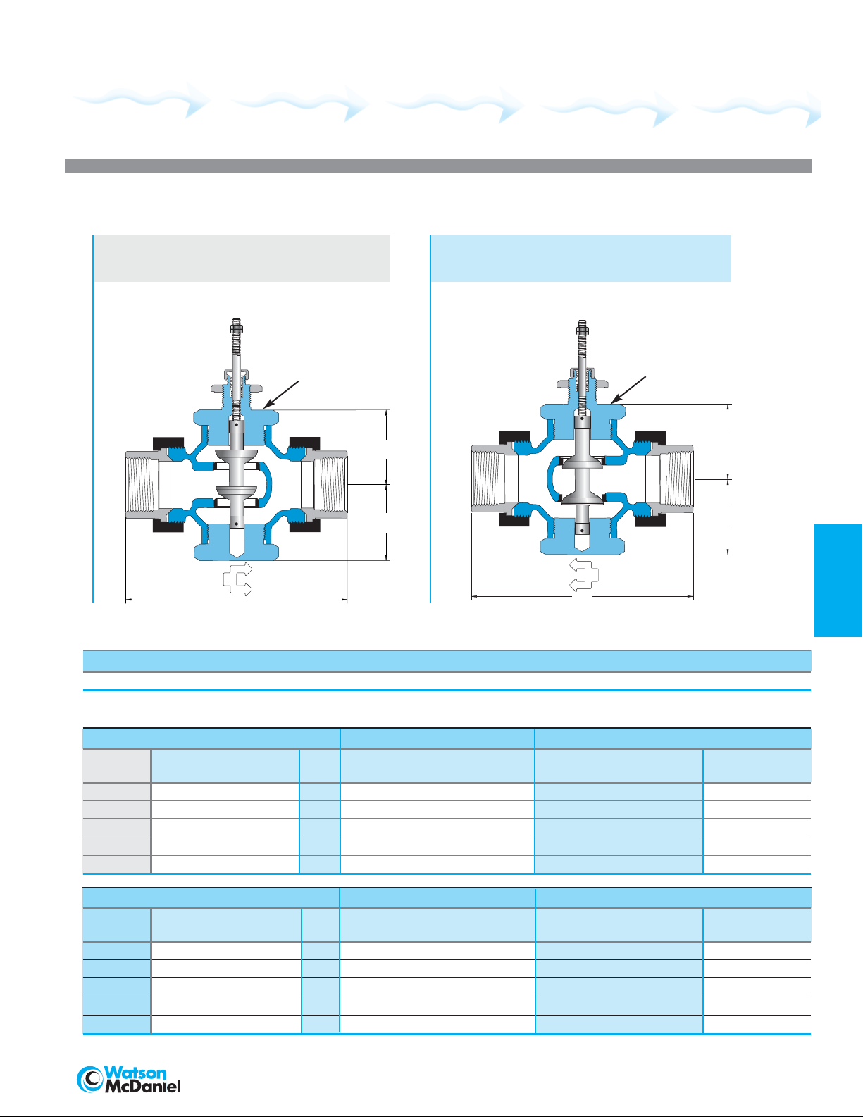
BRONZE
Stem In-to-Close
(normally open)
Single Seat
FLOW
A
A
Actuator
Mounting
Surface
Stem In-to-Close
Double Seat
Single Seat
C
C
B
B
(normally open)
Actuator
Mounting
Surface
Valve Body for W910TB
Stem In-to-Open
(normally closed)
FLOW
A
A
Double Seat
Actuator
Mounting
Surface
C
C
B
B
Stem In-to-Open
(normally closed)
Single or Double Seat
1/2” – 2”
Actuator
Mounting
Surface
CONTROL
VALVES
C
C
C
B
B
FLOW
A
A
FLOW
A
A
C
B
B
Specifications
Body Material Trim Material Trim Style Connection Pressure & Temperature Rating
Bronze Stainless Steel Modified Linear NPT with Malleable Iron Union Ends 250 PSI @ 410°F (210°C)
Valve Body Selection
Valve Body Number
ITC ITO
Normally Normally
Connection
Size
Nominal
Number of
Open Closed (NPT) Port Seats C
A02 A03
A05 A06
A08 A09
A11 A12
A14 A15
A21 A24
1
/2"
1
/2"
1
/2"
1
/2"
1
/2"
3
/4"
1
/8" 1 0.17 250 4.8 [122] 1.8 [46]
3
/16" 1 0.35 250 4.8 [122] 1.8 [46] 1.8 [46] 3.0 lbs [1.35 kg]
1
/4" 1 0.7 250 4.8 [122] 1.8 [46] 1.8 [46] 3.0 lbs [1.35 kg]
3
/8" 1 1.4 250 4.8 [122] 1.8 [46] 1.8 [46] 3.0 lbs [1.35 kg]
1
/2" 1 2.8 250 4.8 [122] 1.8 [46] 1.8 [46] 3.0 lbs [1.35 kg]
3
/4" 2 8 250 5.6 [142] 2.3 [58] 2.3 [58] 5.0 lbs [2.25 kg]
A29 A33 1" 1" 2 12 250 6.0 [152] 2.3 [58] 2.3 [58] 6.1 lbs [2.75 kg]
A39 A44 11/4"1
A50 A55 11/2"1
1
/4" 2 21 250 7.2 [183] 2.6 [66] 2.6 [66] 10.1 lbs [4.55 kg]
1
/2" 2 30 250 7.7 [196] 2.6 [66] 2.6 [66] 11.1 lbs [5.00 kg]
A61 A66 2" 2" 2 47 250 8.6 [218] 3.1 [79] 3.1 [79] 17.0 lbs [7.65 kg]
All dimensions are inches [mm].
428 Jones Boulevard • Limerick Airport Business Center • Pottstown PA • 19464 • Tel: 610-495-5131 • Fax: 610-495-5134
www.watsonmcdaniel.com
Maximum Close-Off Pressure
(PSI ΔP)
Actuator
v
W910TB A B C Shipping Wt.
Dimensions
Approximate
1.8 [46] 3.0 lbs [1.35 kg]
191
Page 9

CONTROL VALVES
W910 Series
Valve Body for W910TB
3-Way • 1/2” – 2”
for Mixing or Diverting
MIXING
FLOW DIAGRAM
AIR
UPPER
PORT
(C)
G
F
AIR
Actuator
Mounting
Surface
LOWER
PORT
(B)
BRONZE
DIVERTING
FLOW DIAGRAM
AIR
AIR
VALVES
CONTROL
CAUTION: 3-Way Valves are not designed for use in steam applications.
To properly control the mixing of two flows, inlet pressures at ports B and C should be as equal as possible.
AIR
Specifications
Body Material Trim Material Trim Style Connection Pressure & Temperature Rating
Bronze Bronze Modified Linear NPT with
Valve Body Selection
Mixing or Diverting
Valve Body
Number
A18
A25
A34 1" 1" 8.4 250 6.0 [152] 2.3 [58] 2.3 [58] 5.7 lbs [2.57 kg]
A45 11/4"1
A56 11/2"1
A67 2" 2" 33 250 8.6 [218] 4.1 [104] 3.1 [79] 16.7 lbs [7.55 kg]
All dimensions are inches [mm].
Size
Connection (NPT) Nominal Port
1
/2"
3
/4"
1
/2" 2.8 250 4.8 [122] 1.8 [46] 1.8 [46] 2.9 lbs [1.31 kg]
3
/4" 5.6 250 5.6 [142] 2.3 [58] 2.3 [58] 4.7 lbs [2.12 kg]
1
/4" 15 250 7.2 [183] 2.8 [71] 2.6 [66] 9.5 lbs [4.28 kg]
1
/2" 21 250 7.7 [196] 3.5 [89] 2.6 [66] 11.1 lbs [5.00 kg]
COMMON
Malleable Iron Union Ends
Maximum Close-Off Pressure (PSI ΔP)
Actuator
C
v
W910TB E F G Shipping Wt.
AIR
E
PORT
(A)
250 PSI @ 300°F (149°C)
Dimensions Approximate
192
428 Jones Boulevard • Limerick Airport Business Center • Pottstown PA
• 19464 • Tel: 610-495-5131 • Fax: 610-495-5134
www.watsonmcdaniel.com
Page 10

CONTROL VALVES
W910 Series
CAST IRON
MIXING
FLOW DIAGRAM
AIR
AIR
Valve Body for W910TB
for Mixing or Diverting
Actuator
Mounting
Surface
LOWER
LOWER
ORT
P
PORT
(B)
(B)
UPPER
PORT
(C)
3-Way • 21/2”–4”
DIVERTING
FLOW DIAGRAM
AIR
G
G
AIR
CONTROL
VALVES
F
F
AIR
COMMON PORT (A)
E
E
COMMON
PORT
(A)
CAUTION: 3-Way Valves are not designed for use in steam applications.
To properly control the mixing of two flows, inlet pressures at ports B and C should be as equal as possible.
AIR
Specifications
Body Material Trim Material Trim Style Connection Pressure & Temperature Rating
Cast Iron Bronze Modified Linear 125# Flanged 125 PSI @ 300°F (149°C)
Valve Body Selection
Mixing or Diverting
Valve Body
Number
B75 21/2"2
B80 3" 3" 72 125 10.0 [254] 8.0 [203] 6.0 [152] 80 lbs [36 kg]
B85 4" 4" 102 125 13.0 [330] 10.0 [254] 6.9 [175] 140 lbs [64 kg]
All dimensions are inches [mm].
Connection (NPT) Nominal Port
Size
1
/2" 58 125 9.0 [229] 7.1 [180] 5.2 [132] 62 lbs [28 kg]
Maximum Close-Off Pressure (PSI ΔP)
Actuator
C
v
W910TB E F G Shipping Wt.
Dimensions Approximate
428 Jones Boulevard • Limerick Airport Business Center • Pottstown PA • 19464 • Tel: 610-495-5131 • Fax: 610-495-5134
www.watsonmcdaniel.com
193
Page 11

CONTROL VALVES
W910 Series
Capacity Charts
CAPACITIES –
Note: All steam capacities based on Critical Drop (Choked Flow).
VALVES
CONTROL
CAPACITIES –
ITC = In-to-Close; ITO = In-to-Open
Steam (lbs/hr)
1/2” 3/4” 1” 11/4”1
Inlet A14/E14 ITC A19/E19 ITC A26/E26 ITC A36/E36 ITC A47/E47 ITC A58/E58 ITC
Pressure
(PSIG) Cv = 2.8 Cv = 5.6 Cv = 8.4 Cv = 15 Cv = 21 Cv = 33
1 80 160 240 428 599 942
3 90 180 270 483 676 1062
5 100 201 301 537 752 1182
10 126 252 377 674 943 1482
15 151 302 454 810 1134 1782
20 177 353 530 946 1325 2082
25 202 404 606 1083 1516 2382
30 228 455 683 1219 1701 2682
40 279 557 838 1492 2089 3283
50 329 659 988 1765 2471 3883
60 380 761 1141 2038 2853 4483
70 431 863 1294 2310 3235 5083
80 482 964 1447 2583 3617 5683
90 533 1066 1599 2856 3999 6283
100 584 1168 1752 3129 4380 6884
125 711 1423 2134 3811 5335 8384
150 839 1677 2516 4493 6290 9884
175 966 1932 2898 5175 7245 11385
200 1093 2187 3280 5857 8200 12885
250 1348 2696 4044 7221 10109 15886
Size, Body Number & Coefficient (Cv)
Water (GPM)
1/2” 3/4” 1” 11/4”1
Pressure A14/E14 ITC A19/E19 ITC A26/E26 ITC A36/E36 ITC A47/E47 ITC A58/E58 ITC
Drop
(PSI ΔP) Cv = 2.8 Cv = 5.6 Cv = 8.4 Cv = 15 Cv = 21 Cv = 33
1 2.8 5.6 8.4 15 21 33
3 4.8 10 15 26 36 57
5 6.3 13 19 34 47 74
10 8.9 18 27 47 66 104
15 11 22 33 58 81 128
20 13 25 38 67 94 148
25 14 28 42 75 105 165
30 15 31 46 82 115 181
40 18 35 53 95 133 209
50 20 40 59 106 148 233
60 22 43 65 116 163 256
70 23 47 70 125 176 276
80 25 50 75 134 188 295
90 27 53 80 142 199 313
100 28 56 84 150 210 330
125 31 63 94 168 235 369
150 34 69 103 184 257 404
175 37 74 111 198 278 437
175 37 74 111 198 278 437
200 40 79 119 212 297 467
225 42 84 126 225 315 495
250 44 89 133 237 332 522
A15/E15 ITO A22/E22 ITO A30/E30 ITO A41/E41 ITO A52/E52 ITO A63/E63 ITO
Size, Body Number & Coefficient (Cv)
SINGLE SEATED VALVES
1
/2”2”
SINGLE SEATED VALVES
1
/2”2”
Note:
Verify that Maximum
Close-Off Pressure does
not exceed max rating
for selected valve body
number and actuator.
(Refer to Valve Body
No. charts for Single
Seated Valves.)
Note:
Verify that Maximum
Close-Off Pressure does
not exceed max rating
for selected valve body
number and actuator.
(Refer to Valve Body
No. charts for Single
Seated Valves.)
194
428 Jones Boulevard • Limerick Airport Business Center • Pottstown PA • 19464 • Tel: 610-495-5131 • Fax: 610-495-5134
www.watsonmcdaniel.com
Page 12

CONTROL VALVES
W910 Series
Capacity Charts
CAPACITIES –
Inlet A21 ITC A29 ITC A39 ITC A50 ITC A61 ITC B73 ITC B78 ITC B83 ITC
Pressure
(PSIG) Cv = 8 Cv = 12 Cv = 21 Cv = 30 Cv = 47 Cv = 69 Cv = 90 Cv = 196
1 288 343 599 856 1342 1970 2569 5595
3 257 386 676 965 1513 2221 2896 6308
5 287 430 752 1075 1684 2472 3224 7021
10 359 539 943 1347 2111 3099 4042 8803
15 432 648 1134 1620 2538 3726 4861 10585
20 505 757 1325 1893 2966 4354 5679 12368
25 578 866 1516 2166 3393 4981 6497 14150
30 650 975 1707 2439 3820 5609 7316 15932
40 796 1194 2089 2984 4675 6864 8953 19497
50 941 1412 2471 3530 5530 8119 10589 23080
60 1087 1630 2853 4075 6385 9380 12240 26650
70 1232 1848 3235 4621 7240 10640 13870 30210
80 1378 2067 3617 5167 8094 11890 15510 33780
90 1523 2285 3999 5712 8949 13150 17150 37350
100 1669 2503 4380 6258 9804 14400 18790 40920
125 2032 3049 5335 7622 11941 17540 22880 49830
150 2396 3594 6290 8986 14078
175 2760 4140 7245 10350 16215
200 3124 4685 8200 11714 18352
250 3851 5777 10109 14442 22625
Note: All steam capacities based on Critical Drop (Choked Flow).
Steam (lbs/hr)
3/4” 1” 11/4”1
Size, Body Number & Coefficient (Cv)
1
/2”2”2
DOUBLE SEATED VALVES
1
/2”3” 4”
CONTROL
VALVES
CAPACITIES –
Pressure A21 ITC A29 ITC A39 ITC A50 ITC A61 ITC B73 ITC B78 ITC B83 ITC
Drop A24 ITO A33 IT0 A44 IT0 A55 IT0 A66 IT0 B74 ITO B79 ITO B84 ITO
(PSI ΔP) Cv = 8 Cv = 12 Cv = 21 Cv = 30 Cv = 47 Cv = 69 Cv = 90 Cv = 196
1 8 12 21 30 47 69 90 196
3 14 21 36 52 81 120 156 339
5 18 27 47 67 105 154 201 438
10 25 38 66 95 149 218 285 620
15 31 46 81 116 182 267 349 759
20 36 54 94 134 210 309 402 877
25 40 60 105 150 235 345 450 980
30 44 66 115 164 257 378 493 1074
40 51 76 133 190 297 436 569 1240
50 57 85 148 212 332 488 636 1386
60 62 93 163 232 364 534 697 1518
70 67 100 176 251 393 577 753 1640
80 72 107 188 268 420 617 805 1753
90 76 114 199 285 446 655 854 1859
100
125 89 134 235 335 525 771 1006 2191
150 98
175 106 159 278 397 622
200 113 170 297 424 665
225 120 180 315 450 705
250 126 190 332 474 743
ITC = In-to-Close; ITO = In-to-Open
Water (GPM)
3/4” 1” 11/4”1
Size, Body Number & Coefficient (Cv)
80 120 210 300 470 690 900 1960
147 257 367 576
1
/2”2” 2
DOUBLE SEATED VALVES
1
/2”3” 4”
428 Jones Boulevard • Limerick Airport Business Center • Pottstown PA • 19464 • Tel: 610-495-5131 • Fax: 610-495-5134
www.watsonmcdaniel.com
195
Page 13

CONTROL VALVES
W910 Series
Capacity Charts
CAPACITIES –
Inlet pressures should be within 5% of each other. Specify if service is for other than water.
VALVES
CONTROL
Note: Oil service or high temperature service requires special O-ring.
Water (GPM)
1/2” 3/4” 1” 11/4”1
Size, Body Number & Coefficient (Cv)
Pressure
Drop A18 A25 A34 A45 A56 A67 B75 B80 B85
(PSI ΔP) Cv = 2.8 Cv = 5.6 Cv = 8.4 Cv = 15 Cv = 21 Cv = 33 Cv = 58 Cv = 72 Cv = 102
1 2.8 5.6 8.4 15 21 33 58 72 102
3 4.8 10 15 26 36 57 100 125 177
5 6.3 13 19 34 47 74 130 161 228
10 8.9 18 27 47 66 104 183 228 323
15 11 22 33 58 81 128 225 279 395
20 13 25 38 67 94 148 259 322 456
25 14 28 42 75 105 165 290 360 510
30 15 31 46 82 115 181 318 394 559
40 18 35 53 95 133 209 367 455 645
50 20 40 59 106 148 233 410 509 721
60 22 43 65 116 163 256 449 558 790
70 23 47 70 125 176 276 485 602 853
80 25 50 75 134 188 295 519 644 912
90 27 53 80 142 199 313 550 683 968
100 28 56 84 150 210 330 580 720 1020
125 31 63 94 168 235 369 648 805 1140
150 34 69 103 184 257 404
175 37 74 111 198 278 437
200 40 79 119 212 297 467
225 42 84 126 225 315 495
250 44 89 133 237 332 522
1
/2”2” 2
1
/2”3”4”
3-WAY VALVES
CAPACITIES –
Inlet
Pressure
(PSIG) Cv = 0.17 Cv = 0.35 Cv = 0.7
1 4.9 10 20 40
3 5.5 11 23 45
5 6.1 13 25 50
10 7.6 16 31 63
15 9.2 19 38 76
20 11 22 44 88
25 12 25 51 101
30 14 28 57 114
40 17 35 70 139
50 20 41 82 165
60 23 48 95 190
70 26 54 108 216
80 29 60 121 241
90 32 67 133 267
100 35 73 146 292
125 43 89 178 356
150 51 105 210 419
175 59 121 241 483
200 66 137 273 547
250 82 168 337
Note: All steam capacities based on Critical Drop (Choked Flow).
Reduced Port Reduced Port
Steam (lbs/hr)
Size, Body Number & Coefficient (Cv)
1/8” 3/16” 1/4” 3/8”
A02 ITC A05 ITC A08 ITC A11 ITC
SINGLE SEATED
Reduced Port Reduced Port
Cv = 1.4
674
CAPACITIES –
essure A02 ITC A05 ITC A08 ITC A11 ITC
Pr
Drop
(PSI ΔP) Cv = 0.17 Cv = 0.35 Cv = 0.7
1 0.2 0.4 0.7
3 0.3 0.6 1.2 2.4
5 0.4 0.8 1.6 3.1
10 0.5 1.1 2.2 4.4
15 0.7 1.4 2.7 5.4
20 0.8 1.6 3.1 6.3
25 0.9 1.8 3.5 7.0
30 0.9 1.9 3.8 7.7
40 1.1 2.2
50 1.2 2.5 4.9 10
60 1.3 2.7 5.4 11
70 1.4 2.9 5.9 12
80 1.5 3.1 6.3 13
90 1.6 3.3 6.6 13
100 1.7 3.5 7.0 14
125 1.9 3.9 7.8 16
150 2.1 4.3
175 2.2 4.6
200 2.4 4.9 10 20
250 2.7 5.5 11 22
ITC = In-to-Close; ITO = In-to-Open
Reduced Port Reduced Port
Water (GPM)
Size, Body Number & Coefficient (Cv)
1/8” 3/16” 1/4” 3/8”
A03 ITO A06 ITO A09 ITO A12 ITO
SINGLE SEATED
Reduced Port Reduced Port
4.4 8.9
8.6 17
9.3 19
Cv = 1.4
1.4
196
428 Jones Boulevard • Limerick Airport Business Center • Pottstown PA
• 19464 • Tel: 610-495-5131 • Fax: 610-495-5134
www.watsonmcdaniel.com
Page 14

CONTROL VALVES
Control Loop
Understanding a Control Loop
SEMI-INSTANTANEOUS WATER HEATER TEMPERATURE CONTROL LOOP
AIR SIGNAL LINE
TA901 I/P
TRANSDUCER
W910 SERIES
TEAM
S
INLET
CONTROL VALVE
WVBSS
BYPASS
LINE
VACUUM
BREAKER
4
Affect
Respond
3
AV2000
AIR VENT
SET
POINT
TA987
AIR FILTER/REGULATOR
AIR INLET
HOT WATER
OUTLET
Compare
2
TR890 CONTROLLER
SEMI-INSTANTANEOUS
WATER HEATER
STEAM
TRAP
Control Loop
A control loop is a process management system designed to
maintain a process variable at a desired set point. Each step in the
loop works in conjunction with the others to manage the system.
Once the set point has been established, the control loop operates
using a four-step process.
1
Sense
COLD
WATER
INLET
Sense
1
Measure the current condition of the process using a
sensor, which can be an electronic (thermocouple, RTD or
transmitter) or mechanical device (thermal system).
2
Compare
Evaluate the measurement of the current condition against
the set point using an electronic or electric contact controller.
3
Respond
React to any error that may exist between the measured
value and set point by generating a corrective pneumatic
or electric control signal.
4
Affect
Actuate a final control element (valve, heater or other
device) that will produce a change in the process variable.
The loop continually cycles through the steps, affecting the
process variable in order to maintain the desired set point.
Watson McDaniel is unique in its ability to provide all of
the necessary components to create a complete
control loop.
RTD or THERMOCOUPLE
TEMPERATURE SENSOR
CONTROL
VALVES
428 Jones Boulevard • Limerick Airport Business Center • Pottstown PA • 19464 • Tel: 610-495-5131 • Fax: 610-495-5134
www.watsonmcdaniel.com
197
Page 15

CONTROL VALVES
Controllers
Design & Operation
Description
A controller is a comparative device that receives an input signal from a measured process variable,
c
ompares this value with that of a predetermined control point value (set point), and determines the
appropriate amount of output signal required by the final control element to provide corrective action
within a control loop. Watson McDaniel offers an
and digital algorithms to perform its receptive, comparative and corrective functions.
Principles of Operation (Electronic PID Controller)
An electronic sensor (thermocouple, RTD or transmitter) installed at the measurement location
continuously sends an input signal to the controller. At set intervals, the controller compares this signal
to a predefined set point. If the input signal deviates from the set point, the controller sends a corrective
electric output signal to the control element. This electric signal must be converted to a pneumatic signal
when used with an air operated valve, such as a Watson McDaniel W910 Series Control Valve. The
conversion can be made using a Watson McDaniel TA901 I/P Transducer, which converts a 4 to 20 mA
electric signal to a 3 to 15 PSI air signal.
Electronic PID Controller, which uses electrical signals
Features (Electronic PID Controller)
An electronic controller is best suited for applications where large load changes are encountered and/or
fast response changes are required. Watson McDaniel Electronic Controllers have full auto-tuning and
PID capabilities, and offer a host of available options, including user selectable inputs and ranges,
VALVES
CONTROL
outputs, setback functions and alarms.
PID Control is a feature of most Watson McDaniel Electronic Controllers. PID combines the proportional,
integral and derivative functions into a single unit.
Auto-Tuning
Auto-tuning will automatically select the optimum values for P, I and D, thus eliminating the need for the
user to calculate and program these values at system startup. This feature can be overridden when so
desired. On some models, the control element can be manually operated.
• Proportional (P) — Proportional control reacts to the size of the deviation from set point when
sending a corrective signal. The size of the corrective signal can be adjusted in relation to the size of
the error by changing the width of the proportional band. A narrow proportional band will cause a
large corrective action in relation to a given amount of error, while a wider proportional band will cause
a smaller corrective action in relation to the same amount of error.
• Integral (I) — Integral control reacts to the length of time that the deviation from set point exists when
sending a corrective signal. The longer the error exists, the greater the corrective signal.
• Derivative (D) — Derivative control reacts to the speed in which the deviation is changing. The cor-
rective signal will be proportional to the rate of change within the process.
198
428 Jones Boulevard • Limerick Airport Business Center • Pottstown PA • 19464 • Tel: 610-495-5131 • Fax: 610-495-5134
www.watsonmcdaniel.com
Page 16

CONTROL VALVES
Controllers
Design & Operation
Selecting an Electronic PID Controller
All Watson McDaniel Electronic Controllers are designed to control the temperature or pressure of general industrial
equipment and should be carefully selected to meet the demands of the particular application. The information contained within this catalog is offered only as a guide to assist in making the proper selection. Selection of the proper
controller is the sole responsibility of the user. Improper application may cause process failure, resulting in possible
personal injury or property damage.
Case Size
Case Size selection is determined by both available and designed space, and controller features.
Watson McDaniel Electronic Controllers are available in the following panel sizes:
48 x 48 mm (1/16 DIN), 72 x 72 mm, 96 x 96 mm (1/4 DIN) and 48 x 96 mm (1/8 DIN).
The depth of the unit varies with the model selected.
Input
The Input is the measurement signal received by the controller from the sensor. A variety of input
types are available, including thermocouple, RTD, voltage and current.
Control Output
The Control Output is the corrective signal transmitted from the controller to the control element.
Various control output types are available, including contact, voltage, current and
solid state relay driver.
Analog Output
The Analog Output is an optional secondary signal that transmits the measurement signal from the
controller to a remote data acquisition device, such as a recorder, personal computer or display unit.
Alarms
Most models can be ordered with alarms, event outputs, or heater break alarms, which signal an
external device to perform a specific task at a predetermined set point.
Setback Function
This feature, optionally available on some models, is designed to provide energy savings in applications
where the process is idled at regular intervals through the connection of an external timer or switch.
CONTROL
VALVES
428 Jones Boulevard • Limerick Airport Business Center • Pottstown PA • 19464 • Tel: 610-495-5131 • Fax: 610-495-5134
www.watsonmcdaniel.com
199
Page 17

CONTROL VALVES
TR890 Series
Electronic PID Controllers • Features PID & Auto-tuning
Specifications
VALVES
CONTROL
Multiple Sizes
+
0.3% Accuracy
Keyboard
Programmable
Reverse or Direct Acting
Manual Output Override
The TR890 Series Electronic
PID Controller is designed for
use on applications where
large load changes are
expected, or extreme
accuracy and fast response
times are needed. With full
auto-tune capabilities and
a large selection of available
inputs, the TR890 Series is
ideally suited for use with
a Watson McDaniel
Control Valve.
Use of a Watson McDaniel
No. TA987 Air Filter/Regulator
is recommended for filtering
and regulating the pressure of
plant compressed air, and for
delivering clean, dry air at
the proper pressure to
pneumatic control devices.
Approximate Shipping Weights:
TR891: 0.4 lbs [0.17 kg]
TR892: 0.6 lbs [0.28 kg]
TR893: 0.7 lbs [0.33 kg]
TR894: 0.5 lbs [0.24 kg]
Models TR891: 48 x 48 mm (1/16 DIN)
Control Control Mode: Auto-Tuning PID
Proportional
Band Integral Time: Off, 1-6000 sec.
Accuracy
Display Process Value: 4 Digit, 20 mm red LED
Inputs Multi: (switchable between)
Control
Output
Power
Requirements
Data Storage
Case Material
Ambient Temp.
Humidity Maximum: 90% RH, non-condensing
Event Outputs
(Contact Capacity: 240 VAC, 1 A/resistive load)
Options:
TR892: 72 x 72 mm
TR893: 96 x 96 mm (1/4 DIN)
TR894: 96 x 48 mm (1/8 DIN)
Action: Reverse acting (field switchable to direct acting)
Off, 0.1-999.9% Full Scale
Derivative Time: Off, 1-3600 sec.
+
0.3%
Set Value: 4 digit, 10.2 mm green LED
Sampling Cycle: 0.25 seconds
Thermocouple: B, R, S, K, E, J, T, N, PL II, WRe5-26 (U,L (DIN 43710)
RTD: Platinum 100 Ω, 3-Wire
mV: (scalable) -10–10, 0-10, 0-20, 0-50, 10-50, 0-100 mV DC
Current: (scalable) 4-20, 0-20 mA
Voltage: -1–1, 0-1, 0-2, 0-5, 1-5, 0-10 VDC
Current: 4-20 mA (load resistance: 600 Ω maximum)
Contact: Proportional cycle,
1-120 sec. (capacity: 240 VAC 2 A resistive / 1.2 A inductive)
SSR Drive Voltage: Proportional cycle 1-120 sec.
(output rating: 12 ± 1.5 VDC / 30 mA maximum)
Voltage: 0-10 VDC
Load Current 2 mA max
Supply Voltage: 100-240 VAC, 50/60 Hz or 24 VAC/VDC 50/60 Hz
Consumption: 100-240 VAC, 15VA
Nonvolatile EEPROM memory
Polyphenylene Oxide (PPO)
14°F (-10°C) to 122°F (50°C)
Dual Event Outputs (High and/or Low Alarms)
Single Event Output + Heater Break Alarm (includes CT30A sensor)
Single Event Output + Heater Break Alarm (includes CT50A sensor)
Analog Output: 0-10 mV DC (output resistance 10 Ω )
Analog Output: 4-20 mA DC (load resistance 300 Ω max )
Analog Output: 0-10 VDC (load current 2 mA max )
Digital Input (switch) including:
Setback Function setting range of -1999 - 5000, standby or DA/RA Selection
Operated by either non-voltage contact or open collector
24 VDC, 8W
24 VAC, 9VA
200
428 Jones Boulevard • Limerick Airport Business Center • Pottstown PA • 19464 • Tel: 610-495-5131 • Fax: 610-495-5134
www.watsonmcdaniel.com
Page 18

CONTROL VALVES
TR890 Series
Electronic PID Controllers
W
H
C
D
A
B
PANEL CUTOUT DIMENSIONS
HOW TO ORDER Sample Order Number: TR893 8 A C 90 1 00
Model Input Control Output Power Supply Event Output Options
TR891 8 Multi A 4-20 mA 90 100-240 VAC, 50/60 Hz 0 None 00 None
TR892 4 mA C On/Off Contact 08 24 VAC/VDC, 50/60 Hz 1 Dual Event 30 Analog Output (0-10 mVDC)
TR893 6 VDC D SSR Driver
TR894 E 0-10 VDC 2 Single Event 60 Analog Output (0-10 VDC)
Event Outputs
2 or 3 require
Control Outputs
C or D
Electronic PID Controller Dimensions – units: inches [mm].
Model ABC DHW
TR891 1.77 [45] 1.77 [45] 0.43 [11] 3.94 [100] 1.89 [48] 1.89 [48]
TR892 2.68 [68] 2.68 [68] 0.43 [11] 3.94 [100] 2.83 [72] 2.83 [72]
TR893 3.63 [92] 3.63 [92] 0.43 [11] 3.94 [100] 3.78 [96] 3.78 [96]
TR894 1.77 [45] 3.63 [92] 0.43 [11] 3.94 [100] 3.78 [96] 3.78 [96]
(high and/or low)
(high or low) and 08 Digital Input (switch)
heater break CT30A 38 Digital Input (switch) with
3 Single Event
(high or low) and
heater break CT50A
40 Analog Output (4-20 mA)
0-10 mVDC* Analog Output
48 Digital Input (switch)
with 4-20 mA* Analog Output
68 Digital Input (switch) with
0-10 VDC* Analog Output
Not available with Model TR891
*
CONTROL
VALVES
Programmable Ranges
Thermocouple Inputs RTD Inputs Current & Voltage Inputs
T/C Range Fahrenheit Range Celsius Range Fahrenheit Range Celsius Range Range
Type Code Range Code Range Code Range Code Range Code
B
*
E 21 0° to 1300°F
J 22 0° to 1100°F
K 18 -150° to 750°F
K 19 0° to 1500°F
K 20 0° to 2200°F
L 28 0° to 1100°F
N 24 0° to 2300°F
PL II 25 0° to 2300°F
R 16 0° to 3100°F
S 17 0° to 3100°F
T 23 -300° to 400°F
U 24 -300° to 400°F
WRe5-26 26 0° to 4200°F
Range Codes are not required for ordering, but are used for field programming.
750°F (400°C) falls below the accuracy range
*
15 0° to 3300°F
01
07
08
04
05
06
14
10
11
02
03
09
13
12
0° to 1800°C 47 -300° to 1100°F
0° to 700°C 48 -150.0° to 200.0°F
0° to 600°C 49 -150° to 600°F
-100.0° to 400.0°C 50 -50.0° to 120.0°F
0° to 800°C 51 0.0° to 120.0°F
0° to 1200°C 52 0.0° to 200.0°F
0° to 600°C 53 0.0° to 400.0°F
0° to 1300°C 54 0° to 1000°F
0° to 1300°C 83 0-2 V
0° to 1700°C 84 0-5 V
0° to 1700°C 85 1-5 V
-199.9° to 200.0°C 86 0-10 V
-199.9° to 200°C 94 0-20 mA
0° to 2300°C 95 4-20 mA
31
32
33
34
35
36
37
38
-200° to 600°C 71 -10–10 mV
-100.0° to 100.0°C 72 0-10 mV
-100.0° to 300.0°C 73 0-20 mV
-50.0° to 50.0°C 74 0-50 mV
0.0° to 50.0°C 75 10-50 mV
0.0° to 100.0°C 76 0-100 mV
0.0° to 200.0°C 81 -1–1 V
0.0° to 500.0°C 82 0-1 V
(User-scalable Readout)
201
Page 19

CONTROL VALVES
TA901 Series
I/P Transducer • Electropneumatic
Specifications
Model
TA901
Input
4-20 mA
Output
1-17 PSIG Per ANSI/FCI 87-2
(can be calibrated to provide
1-9 PSIG or 9-17 PSIG)
Volume Booster
Built-in volume booster allows
flow capacity up to 20 SCFM
VALVES
CONTROL
Connections
Pneumatic: 1/4” NPT
Electric:
1
/2” NPT
4 to 20 mA
Input
3 to 15 PSI
Output
Intrinsically Safe
Zero and Span
Adjustments
The TA901 Electropneumatic (I/P) Transducer converts a milliamp
current signal to a linearly proportional pneumatic output pressure. This
transducer is designed for control applications that require a high degree
of reliability and repeatability. The TA901 is used in the control operation
of valve actuators and pneumatic valve positioners in the petrochemical,
HVAC, energy management, textile, paper, and food & drug industries.
The TA901 I/P Transducer is tested and approved by Factory Mutual as
Intrinsically Safe Class I, II and III, Division I, Groups C, D, E, F and G when
installed in accordance with the Installation, Operation and Maintenance
Instructions. It should be installed in a vertical position in a vibration-free area.
The Watson McDaniel TA987 Air Filter/Regulator is recommended for filtering
and regulating the pressure of plant compressed air, and for delivering clean,
dry air at the proper pressure to pneumatic control devices.
Air Requirements
Clean, oil-free, dry air filtered
to 40 microns
Minimum Supply Pressure:
3 PSIG
Maximum Supply Pressure:
100 PSIG
Sensitivity: < ±0.1% of span
per PSIG
Air Consumption: 0.03 SCFH
typical
Flow Rate: 4.5 SCFM at
25 PSIG supply
Relief Capacity: 2.0 SCFM at
5 PSIG above 20 PSIG setpoint
Mounting
Pipe, panel or bracket in a
vibration-free area. Field
adjustment will be required if
mounted in a nonvertical position.
Adjustment
Adjustable zero and span
Accuracy
Terminal Based Linearity:
< ±0.75% of span
Repeatability: < 0.5% of span
Hysteresis: < 1.0% of span
Response Time: < 0.25 sec. @
3-15 PSIG
Intrinsic Safety
Tested and approved by
Factory Mutual as Intrinsically
Safe Class I, II and III, Division
I, Groups C, D, E, F and G
when installed in accordance
with Installation, Operation and
Maintenance Instructions
Ambient Temperature
-20°F (-30°C) to 140°F (60°C)
Approximate Shipping
Weight
2.1 lbs [0.94 kg]
HOW TO ORDER
Please order using Item Number: TA901
MOUNTING BRACKET
.55 [14.0]
2.88
[73.1]
1.25 [31.8]
Ø
.21 [5.4]
18 GA. WIRE LEADS
18" LONG
202
BLACK-POSITIVE / WHITE-NEGATIVE
428 Jones Boulevard • Limerick Airport Business Center • Pottstown PA • 19464 • Tel: 610-495-5131 • Fax: 610-495-5134
1.10
[27.9]
.55
[14.0]
10-32 UNF-2A X .38 DEEP
MOUNTING HOLES
1.43
[36.2]
1.09
[27.7]
4.24
[107.7]
1/4 NPT
www.watsonmcdaniel.com
1/2
NPT
1.50
[38.1]
.55 [14.0]
Unit: inches [mm].
Ø
1.13
[28.7]
2.18 [55.4]
MAX. SQUARE
1.50
[38.1]
Page 20

CONTROL VALVES
TA987
Air Filter/Regulator
Specifications
Model
TA987
Air Requirements
Maximum Supply Pressure:
250 PSIG
Output Range:
0 to 30 PSIG, adjustable
Sensitivity: 0.036 PSIG
Air Consumption: < 6 SCFH
Cast Aluminum
Housing
Removable Nylon
Mesh Filter
Low Air
Consumption
Drip Well
Air Requirements (cont.)
Flow Rate: 20 SCFM at 100
PSIG supply/20 PSIG output
Relief Capacity: 0.1 SCFM at
5 PSIG above setpoint
Effect of Supply Pressure
Variation: < 0.2 PSIG for
25 PSIG
The TA987 Air Filter/Regulator is recommended for filtering
and regulating the pressure of plant compressed air, and for delivering
clean, dry air at the proper pressure to pneumatic control devices. Supply air
enters the inlet port, passes through the filtering element, and exits through
the reducing valve to the outlet port. The filtering element removes particles
as small as 40 microns. A drip well is provided for the accumulation of oil
and water and a drain cock is included to allow purging of the unit.
The filtering element is readily accessible for cleaning by removal of the
drip well bowl.
The maximum allowable supply pressure to TA987 Air Filter/Regulator
is 250 PSIG. Improper application may cause failure of the regulator,
resulting in possible personal injury or property damage.
Filter
Removes particles 40 microns
or greater
Port Size
1
/4” NPT
Housing
Cast aluminum
Mounting
Side, pipe, panel or
through body
Ambient Temperature
-20°F (-30°C) to 160°F (71°C)
Approximate Shipping
Weight
1.9 lbs [0.86 kg]
CONTROL
VALVES
Units: inches [mm].
.31 [7.9] SQUARE
1.44
[36.6]
GAUGE
PORT
.05 [1.2]
TO C
L
OF
GAUGE
PORT
2.75
[69.9]
3.19
[81.0]
428 Jones Boulevard • Limerick Airport Business Center • Pottstown PA • 19464 • Tel: 610-495-5131 • Fax: 610-495-5134
VENT
2.10
[53.3]
Ø
.44
[11.2]
2.14
[54.4]
.75
[19.1]
OUT
2.06
[52.3]
1.25
[31.8]
2.25
[57.2]
3.19
[81.0]
10-24 UNC
2 HOLES
1/4-20 UNC
.44 [11.1] DEEP
2 HOLES
Ø
.36 [9.1]
THRU 2 HOLES
7.25
[184.2]
www.watsonmcdaniel.com
203
Page 21

CONTROL VALVES
Electronic Temperature Sensors
Connection Head Type • RTD & Thermocouple
The Watson McDaniel
VALVES
CONTROL
3.40
[86.2]
3.91
[99.4]
Thermocouple
or RTD
Cast Aluminum,
Polypropylene
or Stainless
Steel Head
Weather Proof
Welded or
Spring Loaded
Stem
Ø
3.30
[83.8]
1/2 NPT
Ø
.25
[6.4]
Units: inches [mm]
STEM
LENGTH
Connection Head is
available with both Type J
and Type K Thermocouples,
as well as RTD sensors. The
weather proof head provides
a conduit connection and is
available in cast aluminum
(screw cover), polypropylene
(flip cover) and stainless steel
(screw cover). The stem is either
1
welded directly to the
/2”NPT
threaded connection, or is
spring-loaded to provide
maximum sensitivity. The
spring-loaded stem must always
be installed in a thermowell.
Extension wire and transmitter
accessories are also available.
Please consult factory.
For applications where
the process media may
be corrosive or contained
under pressure, the use of
a thermowell is required to
prevent damage to the sensor
and facilitate its removal from
the process. To prevent leakage
of the process media, spring
loaded sensors must always
be installed in a thermowell.
Sensor Specifications
Thermocouple
Type Color Code Positive Lead Negative Lead Temperature Range
J Black Iron* (Fe) Constantan (Cu-Ni) 32° to 1382°F
K Yellow Nickel-Chromium (Ni-Cr) Nickel-Aluminum* (Ni-Al) 32° to 2282°F
*magnetic lead
RTD
Type Material Resistance @ 0°C Temperature Coefficient Temperature Range
D Platinum (Pt) 100 Ω Ω a = 0.00385 Ω/Ω/°C -50° to 700°F
M Platinum (Pt) 1000 Ω a = 0.00385 Ω/Ω/°C -50° to 700°F
[white] [red] (0° to 750°C)
[yellow] [red] (0° to 1250°C)
Specifications
Sensors Description
TJD Type J T/C
TKD Type K T/C
TDD 100 Ω RTD
TMD 1000 Ω RTD
Hot Junction
T/C: Ungrounded
RTD: Platinum, 3-Wire
Stem
Insulation
Head
Process Connection
Conduit Connection
Approximate Shipping Weight
316 stainless steel
1
/4"
diameter
Ceramic
Cast aluminum, polypropylene or
stainless steel
1
/2” NPT welded or spring-loaded
3
/4” NPT Female
1.1 lbs [0.50 kg]
(-45° to 400°C)
(-45° to 400°C)
HOW TO ORDER Sample Order Number: TJD Z 04 U W A
Sensor Stem Style Stem Length Hot Junction Connection Head Material
TJD Type J T/C Z 316SS, 1/4” O.D. 02 21/2" Stem U Ungrounded (T/C) S Spring Loaded, A Aluminum
TKD Type K T/C 04 4" Stem D 3-Wire (RTD)
TDD 100 Ω RTD 06 6" Stem W Welded, S Stainless Steel
TMD1000 Ω RTD 09 9" Stem
12 12" Stem
Other sensor styles available. Other Lengths: Specify in inches (24" maximum)
Please consult factory.
204
428 Jones Boulevard • Limerick Airport Business Center • Pottstown PA • 19464 • Tel: 610-495-5131 • Fax: 610-495-5134
www.watsonmcdaniel.com
1
/2” NPT P Polypropylene
1
/2” NPT
Page 22

CONTROL VALVES
Thermowells
for RTD & Thermocouple Temperature Sensors
Standard (21/2" - 6")
STEM LENGTH
1/2 NPSM
.40 [10]
with Lagging Extension (4” - 24”)
(A)
(P)
EXTERNAL
THREAD
U
LENGTH
.61 [15]
1/2 NPSM
.75 [19]
Ø
.260 [7]
Ø
.44 [11]
LAGGING
EXTENSION
(T)
Standard (9” - 24”)
1/2 NPSM
(P)
1.00
[25]
U
LENGTH
.75 [19]
(A)
STEM LENGTH
1.00
[25]
EXTERNAL THREAD
(P)
EXTERNAL
THREAD
(A)
STEM LENGTH
LENGTH
Ø
.260 [7]
U
Ø
.50 [13]
Ø
.260 [7]
Ø
.50 [13]
Units inches: [mm]
CONTROL
VALVES
Lengths
(A) U (T) U
Stem Length Length Lagging Extension Length
21/2" 1.75 [44] — —
4” 2.50 [64] 1.00 [25] 1.50 [38]
6” 4.50 [114] 2.00 [51] 2.50 [64]
9” 7.50 [191] 3.00 [76] 4.50 [114]
12” 10.50 [267] 3.00 [76] 7.50 [191]
15” 13.50 [343] 3.00 [76] 10.50 [267]
18” 16.50 [419] 3.00 [76] 13.50 [343]
24” 22.50 [572] 3.00 [76] 19.50 [495]
Standard Lagging
Selection of the proper thermowell is the sole responsibility of the user. Temperature and pressure limitations must be considered.
Improper application may cause failure of the thermowell, resulting in possible personal injury or property damage. For correct use
and application, please refer to the Thermowells For Thermometers And Electrical Temperature Sensors Standard ASME B40.9.
HOW TO ORDER Sample Or
mowell Style (P) External Thread (A) Stem Length (T) Lagging Extension Material
Ther
1
76 -Sensor, Stepped Shank 3
1
(2
/2" - 6" Stem 43/4NPT G 4" Stem C 2" Extension (6" Stem only) 3 Steel
Straight Shank)
*Not available with 2
1
/2" Stem Length
Other thermowell styles available. Please consult factory.
/2NPT* D 21/2" Stem A 1" Extension (4" Stem only) 2 Brass
5 1 NPT* J 6" Stem E 3" Extension (9" thru 24” Stem only) 4 Monel
M 9" Stem Omit if No Extension 5 304SS
R 12" Stem 6 316SS
V 15" Stem
Wa 18" Stem
Wk 24" Stem
Pressure Ratings (PSI)
Operating Temperature
Material
Carbon steel 5000 5000 4800 4600 3500 -
304 stainless steel 6550 6000 4860 4140 3510 3130
316 stainless steel 6540 6400 6000 5270 5180 4660
Monel 5530 4990 4660 4450 4450 -
Brass 3170 PSI @ 150˚F, 2930 PSI @ 350˚F
70°F 200°F 400°F 600°F 800°F 1000°F
der Number:
76-4J6
428 Jones Boulevard • Limerick Airport Business Center • Pottstown PA • 19464 • Tel: 610-495-5131 • Fax: 610-495-5134
www.watsonmcdaniel.com
205
 Loading...