

Page 1

Straight through control valve with post guided plug
1“ to 8“
STEVI® 470 / 471 - ANSI
Electric actuator ARI-PREMIO
• Enclosure IP 65
• 2 torque switches
• 1 travel switch
• Handwheel
• Additional devices available,
e.g. potentiometer
STEVI® 470 / 471 - ANSI
with electric and pneumatic actuators
STEVI® 470 / 471 - ANSI
Electric actuator AUMA SAR
• Electric multiturn actuator capable of
high closing pressures
• Enclosure IP 67
• 2 torque switches
• 2 travel switches
• Handwheel
• Overheating protection for motor as standard
• Additional devices available,
e.g. potentiometer
• Explosion proof execution available
STEVI® 470 / 471 - ANSI
Pneumatic actuator DP32 - DP34
• Reversible pneumatic actuator
• Actuator with rolling diaphragm
• Air supply pressure max. 87 psi
• Stem protection by bellow
• Maintenance-free O-ring sealing
• Assembly of additional devices
acc. to DIN IEC 60534-6
Page 2
Page 4
Fig. 470 - ANSI
Edition 10/04 - Data subject to alteration
Page 6
Features:
• Compact design
• Precision guided stem
• Burnished stem
• Tapered seat joint
• Replaceable seat ring and plug
• Threaded seat ring
• Cv-values reducible up to 6 times
• Rangeability 50 : 1 (1“-6“)
30 : 1 (8“)
• Post guided plug
• Spring loaded PTFE-V-ring packing unit
• Two-ply bellows seal
• Travel indicator
Fig. 471 - ANSI
1
Page 2

(Material and Figure-No.
refer to technical data
or part list.)
495-1124 lbf: 6.5 x 5.9
2698-3372 lbf: 7.9 x 6.9
495-1124 lbf: 1.9
2698-3372 lbf: 3.5
5.1
4.7
495-1124 lbf = ∅
2698-3372 lbf = ∅
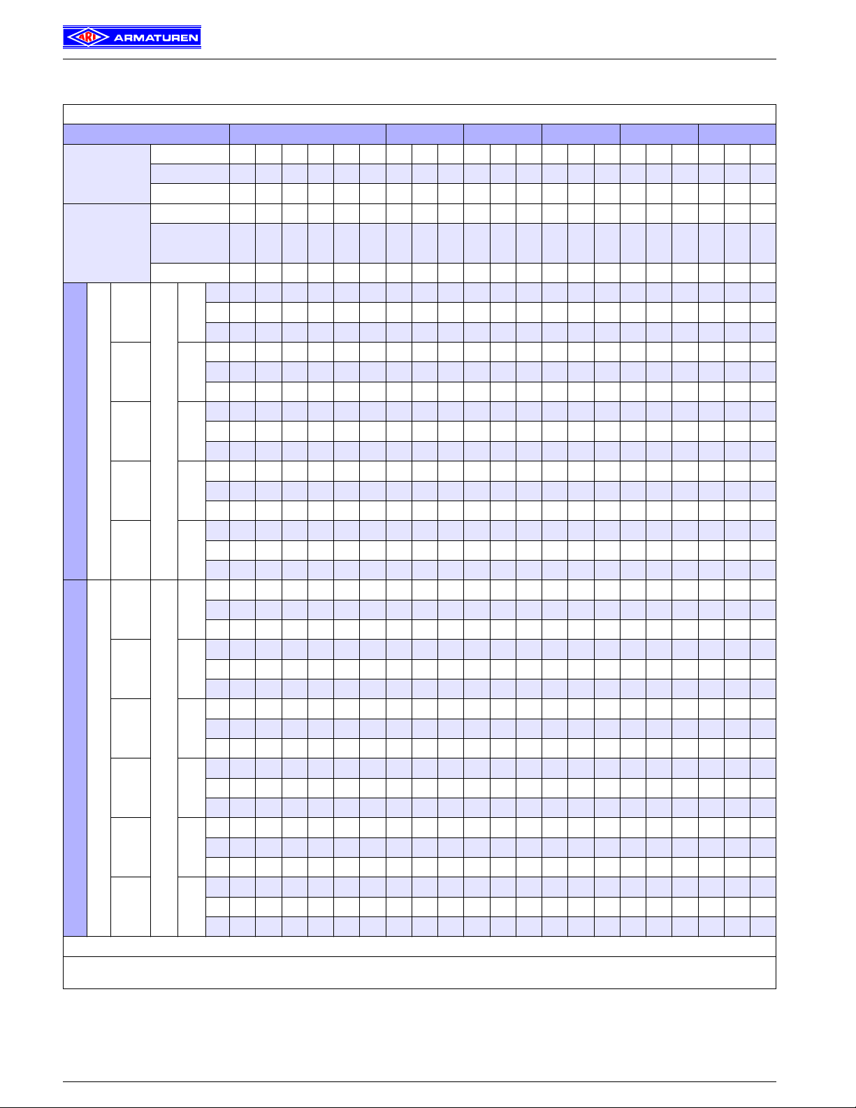
STEVI® 470 / 471 - ANSI
with electric actuator ARI-PREMIO
Fig. 470 - ANSI Fig. 471 - ANSI
Heights and weights
Size 1“ 1 1/2“ 2“ 3“ 4“ 6“ 8“
H (in) 23.1 24.3 24.3 25.5 25.6 28.8 31.1
495 lbf
1124 lbf 37.5 55.1 59.5 103.6 160 294 497
...470
H (in) 30.2 30.2 31.4 31.5 34.6 37.5
2698 lbf
3372 lbf
(lb)
(lb) 63.9 68.4 112.5 169 303 506
35.1 52.7 57.1 101.2 157 292
H (in) 29.3 32.6 32.6 33.3 34.5 41.7 50
495 lbf
1124 lbf 43.7 64.4 68.8 116.9 167 312 522
...471
H (in) 38.5 38.5 39.3 40.4 47.5 56.4
2698 lbf
3372 lbf
(lb)
(lb) 73.2 77.6 125.7 176 321 530
41.2 62 66.4 114.4 165 310
Other dimensions refer to page 12.
2
Edition 10/04 - Data subject to alteration
Page 3

STEVI® 470 / 471 - ANSI
Closing pressures with ARI-PREMIO
max. permissible closing pressures for parabolic plug on flow to open P
2
= 0
(Observe pressure-temperature-limits on page 13. Plug design acc. to „Selection of flow restrictors“, refer to page 13.)
Size 1“ 1 1/2“ 2“ 3“ 4“ 6“ 8“
0.98 1.57 1.97 3.15 3.94 5.91 7.87
12 29 46 116 185 462 728
0.79 1.18 1.18 1.18 1.18 1.97 2.56
Standard
Cv-values
Reduced
Cv-values
Seat-∅(in)
3)
Cv-value
Tr av e l (in)
Seat-∅(in)
Cv-value
Tr av e l (in)
0.12 0.2 0.47 0.71 0.87 0.98 1.26 1.26 1.57 1.97 2.56 2.56 3.15 3.94 4.92 4.92 5.91
0.29
0.18
0.12
0.79 0.79 0.79 0.79 0.79 0.79 0.79 0.79 1.18 1.18 1.18 1.18 1.18 1.18 1.97 1.97 1.97
0.73
0.46
2.9
1.8
4.6 7.3 12 18 18 29 46 73 73 116 185 289 289 462
1.2
I. 740 740 740 740 677 521 510 306 191 306 191 117 116 64 39 64 39 22 22
Actuator
ARI-PREMIO
495 lbf
(psi)
Operating time2)(s)
II. 740 740 740 740 634 488 466 279 173 279 173 106 103 56 34 56 34 19 19
III. 461 457 442 430 421 415 415 262 162 262 162 99 99 54 32 54 32 18 15
53 53 79 53 79 79 79 79
Closing pressure
1)
I. 740 740 740 740 502 740 502 318 316 183 118 183 118 73 73 45 29
Actuator
ARI-PREMIO
1124 lbf
(psi)
Operating time2)(s)
II. 740 740 740 740 484 740 484 306 303 176 113 176 113 70 70 42 28 40 26
III. 580 580 580 580 580 580 580 580 473 580 473 299 299 173 111 173 111 69 66 40 26 40 26
53 53 79 53 79 79 79 79 132 132
Closing pressure
1)
I. 740 740 740 740 482 316 482 316 200 200 126 86
Actuator
ARI-PREMIO
2698 lbf
(psi)
Operating time
II. 740 740 740 740 474 311 474 311 197 197 124 85 121 83 45
III. 580 580 580 580 472 309 472 309 196 193 122 83 122 83 45
2)
(s)
38 38 38 38 38 63 63 82
Closing pressure
1)
I. 610 401 610 401 255 255 161 111
Actuator
ARI-PREMIO
3372 lbf
(psi)
Operating time
II. 602 396 602 396 252 252 159 109 156 107 59
III. 580 394 580 394 250 248 157 107 157 107 59
2)
(s)
79 79 79 132 132 171
Closing pressure
1)
I. Fig. 470: PTFE-V-ring unit II. Fig. 470: PTFE- / pure graphite-packing III. Fig. 471: Bellows seal
171
1)
Motor voltage: 230V 50/60Hz
24V 50/60Hz; 115V 50/60Hz
Technical data for actuator refer to data sheet ARI-PREMIO
2)
Indicated operating times with 50 Hz.
3)
Not for perforated plug (presentation refer to page 13). Please find the Cv-values on page 13.
Edition 10/04 - Data subject to alteration
3
Page 4

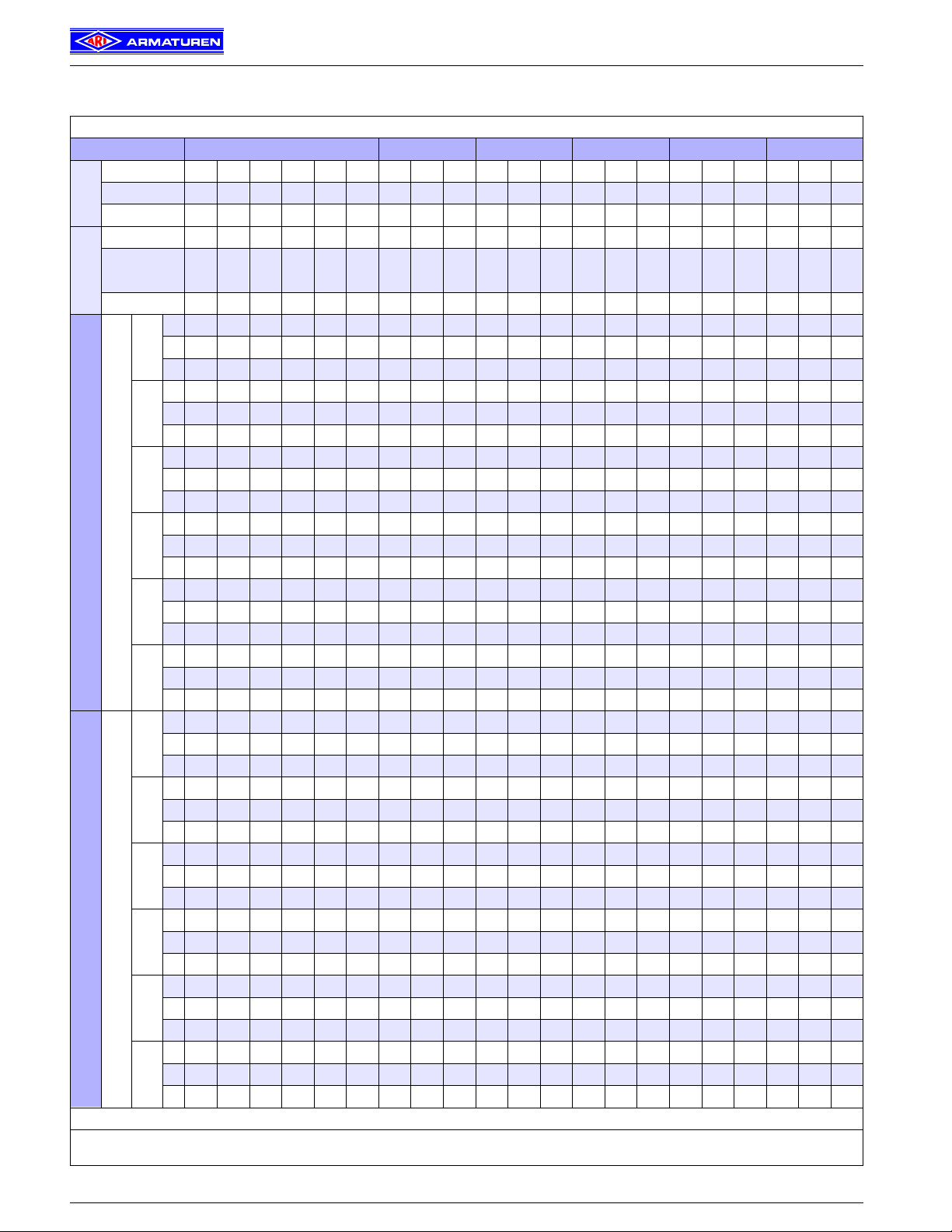
STEVI® 470 / 471 - ANSI
with electric actuator AUMA SAR (MATIC)
= 5.7
= 10.4
= 11.1
= 9.8
= 10
(Material and Figure-No.
refer to technical data
or part list.)
Fig. 470 - ANSI Fig. 471 - ANSI
Heights and weights
Size 1 1/2“ 2“ 3“ 4“ 6“ 8“
H (in) 25.9 25.9 27 27.1 29.5 33.2
SAR 07.1
SAR 07.5
...470
...471
Other dimensions refer to page 12. (For execution with AUMA SAR Ex other heights.)
4
H (in) 27.5 27.6 30 33.7
SAR 10.1
H (in) 35 36.7
SAR 14.1
H (in) 34.2 34.2 34.9 36.1 42.4 50.7
SAR 07.1
SAR 07.5
H (in) 35.4 36.6 42.8 51.2
SAR 10.1
(lb)
(lb)
(lb)
(lb)
(lb)
98.8 106.5 150.6 207 341 544
160.5 217 351 554
426 629
108 115.8 163.8 214 359 568
173.8 224 369 587
Edition 10/04 - Data subject to alteration
Page 5

max. permissible closing pressures for parabolic plug on flow-to-open P2 = 0
Fig. 470 - ANSI
Size 1 1/2“ 2“ 3“ 4“ 6“ 8“
Standard
Cv-values
Reduced
Cv-values
Actuator
AUMA
SAR 07.1
Output drive.
Form A
TR 20 x 4
Actuator
AUMA
SAR 07.5
Output drive
Form A
TR 26 x 5
Actuator
AUMA
SAR 10.1
Output drive
Form A
TR 26 x 5
Actuator
AUMA
SAR 14.1
Output drive
Form A
TR 30 x 6
Fig. 471 - ANSI
Size 1 1/2“ 2“ 3“ 4“ 6“ 8“
Standard
Cv-values
Reduced
Cv-values
Actuator
AUMA
SAR 07.1
Output drive.
Form A
TR 20 x 4
Actuator
AUMA
SAR 07.5
Output drive
Form A
TR 26 x 5
Actuator
AUMA
SAR 10.1
Output drive
Form A
Motor voltage: 400V 50Hz 3∼ (other voltages on request)
1)
TR 26 x 5
Indicated operating times with 50 Hz
Not for perforated plug (presentation refer to page 13). Please find the Cv-values on page 11.
2)
3)
STEVI® 470 / 471 - ANSI
Closing pressures with AUMA SAR
(Observe pressure-temperature-limits on page 13. Plug design acc. to „Selection of flow restrictors“, refer to page 13.)
Seat-∅(in)
3)
Cv-value
Tr av e l (in)
Seat-∅(in)
Cv-value
Tr av e l (in)
1)
Closing
pressure (psi)
shut off 740 740 740 740 740 740 740 673 443 673 443 282
controlling 740 740 740 740 740 545 542 318 207 318 207 130
0.98 1.26 1.26 1.57 1.97 2.56 2.56 3.15 3.94 4.92 4.92 5.91
12 18 18 29 46 73 73 116 185 289 289 462
0.79 0.79 0.79 1.18 1.18 1.18 1.18 1.18 1.18 1.97 1.97 1.97
Torque (ft lbf) 22
Operating time
2)
(s)
Output drive (rpm) 5.6 8 5.6 8 8 8
1)
Closing
pressure (psi)
shut off 740 740 740 624 740 624 398 398 253 175 251 173 96
controlling 740 740 455 298 455 298 189 189 119 81 116 79 43
Torque (ft lbf) 33 44
Operating time
2)
(s)
Output drive (rpm) 5.6 5.6 5.6 5.6 11 11 11
1)
Closing
pressure (psi)
shut off 740 733 740 733 468 678 433 300 520 360 301
controlling 740 624 740 624 398 398 253 175 251 173 96
Torque (ft lbf) 52 74 89
Operating time
2)
(s)
Output drive (rpm) 5.6 5.6 5.6 11 11 11
1)
Closing
pressure (psi)
shut off 740 619 429 619 429 240
controlling 656 419 290 419 290 162
Torque (ft lbf) 129
Operating time
2)
Closing pressures valid
for PTFE-V-ring unit
and PTFE- / pure graphitepacking.
(s)
Output drive (rpm) 8 11 11 11
Seat-∅(in)
3)
Cv-value
Tr av e l (in)
Seat-∅(in)
Cv-value
Tr av e l (in)
1)
Closing
pressure (psi)
shut off 580 580 580 580 580 580 580 580 441 580 441 281
controlling 580 580 580 580 580 538 538 206 315 315 206 129
0.98 1.26 1.26 1.57 1.97 2.56 2.56 3.15 3.94 4.92 4.92 5.91
12 18 18 29 46 73 73 116 185 289 289 462
0.79 0.79 0.79 1.18 1.18 1.18 1.18 1.18 1.18 1.97 1.97 1.97
Torque (ft lbf) 22
Operating time
2)
(s)
Output drive (rpm) 5.6 8 5.6 8 8 8
1)
Closing
pressure (psi)
shut off 580 580 580 580 580 580 397 395 251 173 251 173 96
controlling 580 580 452 296 452 296 188 185 116 79 116 79 43
Torque (ft lbf) 33 44
Operating time
2)
(s)
Output drive (rpm) 5.6 5.6 5.6 5.6 11 11 11
1)
Closing
pressure (psi)
shut off 580 580 580 580 467 580 430 298 430 298 166
controlling 580 580 580 580 397 395 251 173 251 173 96
Torque (ft lbf) 52 74
Operating time
2)
Closing pressures valid for
design with bellows seal.
Higher closing pressures for
6“ in connection with
(s)
AUMA SAR 14.1 on request.
Output drive (rpm) 5.6 5.6 5.6 11 11 11
1.57 1.97 3.15 3.94 5.91 7.87
29 46 116 185 462 728
1.18 1.18 1.18 1.18 1.97 2.56
54 56 54 56 56 56
64 64 64 64 55 55 71
64 64 64 55 55 71
38 45 45 59
1.57 1.97 3.15 3.94 5.91 7.87
29 46 116 185 462 728
1.18 1.18 1.18 1.18 1.97 2.56
54 56 54 56 56 56
64 64 64 64 55 55 71
64 64 64 55 55 71
Edition 10/04 - Data subject to alteration
5
Page 6

(Material and Figure-No.
refer to technical data
or part list.)
STEVI® 470 / 471 - ANSI
with pneumatic actuator DP 32 - 34
Fig. 470 - ANSI
6
Fig. 471 - ANSI
Edition 10/04 - Data subject to alteration
Page 7

STEVI® 470 / 471 - ANSI
Closing pressures with DP
Heights and weights
Size 1“ 1 1/2“ 2“ 3“ 4“ 6“ 8“
∅ A (in) 9.8
H (in) 18.6 19.8 19.8 20.6 20.6 23
...470
DP 32
DP 33
DP 34
H (in) 24.8 28.1 28.1 28.4 29.6 35.9
...471
∅ A (in) 11.8
H (in) 20.8 22 22 23.1 23.2 25.6
...470
H (in) 27 30.3 30.3 31 32.2 38.5
...471
∅ A (in) 15.9
H (in) 27.3 27.3 28.5 28.5 30.9 33.2
...470
H (in) 35.6 35.6 36.3 37.5 43.8 49.3
...471
(lb) 43 60.6 65 109.1 165 300
(lb) 49.2 69.9 74.3 122.4 173 318
(lb) 56.2 73.9 78.3 122.4 179 313
(lb) 62.4 83.1 87.5 135.6 186 331
(lb) 140 144.4 188.5 245 379 582
(lb) 149.3 153.7 201.8 252 397 606
Other dimensions refer to page 12.
Top mounted handwheel Technical data for actuator refer to data sheet DP32-34T
Type of actuator DP 32 DP 33 DP 34
∅ D1 (in) 8.9 11.8 15.7
H1 (in) 10.6 11.2 17.4
Weight (lb) 11.3 17.6 37.5
Edition 10/04 - Data subject to alteration
7
Page 8
STEVI® 470 / 471 - ANSI
Closing pressures with DP
max. permissible closing pressures for parabolic plug on flow-to-open P
2
= 0
(Observe pressure-temperature-limits on page 13. Plug design acc. to „Selection of flow restrictors“, refer to page 13.)
Spring closes on air failure
Size 1“ 1 1/2“ 2“ 3“ 4“ 6“
Seat-∅ (in) 0.98 1.57 1.97 3.15 3.94 5.91
Cv-value 12 29 46 116 185 462
Travel (in) 0.79 1.18 1.18 1.18 1.18 1.97
Seat-∅ (in) 0.12 0.2 0.47 0.71 0.87 0.98 1.26 1.26 1.57 1.97 2.56 2.56 3.15 3.94 4.92
Cv-value
0.29
0.18
0.12
0.73
0.46
2.9
1.8
4.6 7.3 12 18 18 29 46 73 73 116 185 289
1.2
Travel (in) 0.79 0.79 0.79 0.79 0.79 0.79 0.79 0.79 1.18 1.18 1.18 1.18 1.18 1.18 1.97
I. 444 423 308 118 69 47 36
3 - 15
17
II. 290 269 173 55 26 14
III.
I. 740 740 740 374 243 183 172 97 55 97 55 30 29
6 - 17 20
II. 740 740 724 311 200 150 128 69 38 69 38 19 16
III. 141 137 122 109 101 95 95 52 27 52 27
I. 740 592 455 444 265 164 265 164 100 99 54 32 54 32 18 18
12 - 35 39
II. 740 740 549 422 399 238 146 238 146 89 86 46 27 46 27 15 15
III. 398 394 379 367 358 352 352 220 135 220 135 82 82 44 25 44 25
I. 740 740 740 559 559
22 - 36 41
Air supply pressure min. (psi)
II. 740 740 740 532 532
III. 580 580 580 580 580 580 580 515 515
I. 740 740
29 - 48 52
II. 740 740
III. 580 580
c)
c)
c)
c)
c)
c)
a)62 a)33 a)62 a)33 a)16 a)
128
116
a)
18
c)
a)
a)
a)
a)
344
333
196
120
c)
a)
a)
311
288
a)
a)
247
247
a)
740 464 293 464 293 183 182 103 65 103 65 39 39
740
a)
721 437 275 437 275 172 169 96 60 96 60 36 36
740
169
152
102
a)91 a)
a)
196
120
a)
169
102
a)91 a)53 a)
152
a)72 a)
a)60 a)
14
70 37 21 37 21
57 29 16 29 16
53 26 14 26 14
3 - 15
6 - 17 20
12 - 35 39
I.
17
II.
III.
I.
II.
III.
I.
II.
740
634
269
740
c)
c)
662
641
499
a)84 a)69 a)57 a)48 a)42 a)42 a)18 a)
88
740
c)
c)
740
740
740
a)
a)
293
289
274
172
c)
c)
c)94 c)72 a)35 a)16 a)35 a)16 a)
207
129
c)
c)
c)
580
449
c)
c)
c)
580
407
a)
a)
a)
262
253
a)
a)
740
740
a)
a)
740
740
III. 580 580 580 580 580 580 580 420 264 420 264 165 165 93 58 93 58 35 32
I. 596 596 379 377 220 142 220 142 89 89
22 - 44 48
Air supply pressure min. (psi)
II. 578 578 367 364 212 137 212 137 85 85
III. 567 567 360 360 209 135 209 135 84 81
I. 740 740
25 - 39
II. 740 740 740
45
III. 580 580
I. 740 740 518 517 303 197 303 197 124 124
29 - 58 65
II. 740 740 507 504 295 192 295 192 121 121
III. 580 580 499 499 293 191 293 191 120 117
Standard
Cv-values
Reduced
Cv-values
Actuator DP 32
Actuator DP 33
2)
Control signal (psi)
Control signal (psi)
I. Fig. 470: PTFE-V-ring unit II. Fig. 470: PTFE- / pure graphite-packing III. Fig. 471: Bellows seal
Air supply pressure max. of pneumatic actuators DP: 87 psi
Air supply pressure max. limit of control valve: a) 73 psi b) 65 psi c) 58 psi d) 51 psi e) 44 psi
2)
Not for perforated plug (presentation refer to page 13). Please find the Cv-values on page 11.
8
Edition 10/04 - Data subject to alteration
Page 9

STEVI® 470 / 471 - ANSI
Closing pressures with DP
max. permissible closing pressures for parabolic plug on flow-to-open P2 = 0
(Observe pressure-temperature-limits on page 13. Plug design acc. to „Selection of flow restrictors“, refer to page 13.)
Spring closes on air failure
Size 1“ 1 1/2“ 2“ 3“ 4“ 6“ 8“
Seat-∅ (in) 0.98 1.57 1.97 3.15 3.94 5.91 7.87
Cv-value 12 29 46 116 185 462 728
Travel (in) 0.79 1.18 1.18 1.18 1.18 1.97 2.56
Seat-∅ (in) 0.71 0.87 0.98 1.26 1.26 1.57 1.97 2.56 2.56 3.15 3.94 4.92 4.92 5.91
Standard
Cv-values
2)
Reduced
Cv-values
Cv-value 4.6 7.3 12 18 18 29 46 73 73 116 185 289 289 462
Travel (in) 0.79 0.79 0.79 0.79 0.79 1.18 1.18 1.18 1.18 1.18 1.18 1.97 1.97 1.97
3 - 15
6 - 17 20
12 - 35 39
I.
17
II.
III.
I.
II.
III.
I.
II.
III.
121
103
92
295
277
266
644
626
580
e)
e)
e)
d)
d)
d)
b)
b)
b)
e)72 e)
121
e)61 e)
103
e)54 e)54 b)27 b)14 b)27 b)14 b)
92
d)
295
d)
277
d)
266
b)
644
b)
626
b)
580
71 37 21 37 21
58 29 16 29 16
d)
183 104 66 104 66 39 39 23 14
185
d)
170 96 61 96 61 36 36 21 18
173
d)
b)94 b)59 b)94 b)59 b)35 b)
166
166
b)
408 238 154 238 154 96 96 60 40
409
b)
395 230 149 230 149 93 93 57 38 55 36
398
b)
391 228 148 228 148 92 89 55 37 55 37
391
32 18 18
15 - 29 39I.II. 26
III. 26
I. 124 84
22 - 44 48
Actuator DP 34
Control signal (psi)
30 - 44 48
Air supply pressure min. (psi)
II. 122 83 119 81
III. 119 81 119 81
I.
II.
740
740
a)
a)
III.
740
740
a)
a)
740 740 443 673 443 282 282
740
a)
a)
740 740 438 666 438 279 279
740
a)
580 580 436 580 436 277 275
580
I. 169 116
29 - 58 65
II. 167 115 165 113 62
III. 165 113 165 113 62
I. 740 510 740 510 325 325
35 - 52 58
II. 740 505 740 505 321 321
III. 503 503 320 318
I. Fig. 470: PTFE-V-ring unit II. Fig. 470: PTFE- / pure graphite-packing III. Fig. 471: Bellows seal
Air supply pressure max. of pneumatic actuators DP: 87 psi
Air supply pressure max. limit of control valve: a) 73 psi b) 65 psi c) 58 psi d) 51 psi e) 44 psi
Higher closing pressures for 6“/8“ in connection with DP34T on request.
2)
Not for perforated plug (presentation refer to page 13). Please find the Cv-values on page 11.
Edition 10/04 - Data subject to alteration
9
Page 10
STEVI® 470 / 471 - ANSI
Closing pressures with DP / Technical data
max. permissible closing pressures for parabolic plug on flow-to-open P2 = 0
(Observe pressure-temperature-limits on page 13. Plug design acc. to „Selection of flow restrictors“, refer to page 13.)
Spring opens on air failure
Size 1“ 1 1/2“ 2“ 3“ 4“ 6“
Seat-∅ (in) 0.98 1.57 1.97 3.15 3.94 5.91
2)
Cv-value 12 29 46 116 185 462
Cv-values
Standard
Travel (in) 0.79 1.18 1.18 1.18 1.18 1.97
Seat-∅ (in) 0.12 0.2 0.47 0.71 0.87 0.98 1.26 1.26 1.57 1.97 2.56 2.56 3.15 3.94 4.92
Cv-value
Reduced
Cv-values
0.18
0.12
Travel (in) 0.79 0.79 0.79 0.79 0.79 0.79 0.79 0.79 1.18 1.18 1.18 1.18 1.18 1.18 1.97
I. 740 740 740 374 243 183 172 97 55 97 55 30 29
0.29
20
II. 740 740 724 311 200 150 128 69 38 69 38 19 16
III. 141 137 122 109 101 95 95 52 27 52 27
I. 740 740 591 580 349 219 349 219 135 134 75 46 75 46 27 27
29
II. 740 740 723 557 535 322 201 322 201 124 121 67 41 67 41 23 23
III. 527 523 508 496 487 481 481 304 190 304 190 117 117 64 39 64 39 22 20
I. 740 740 740 490 740 490 311 309 179 115 179 115 71 71
II. 740 740 740 740 473 740 473 299 296 171 110 171 110 68 68
44
III. 580 580 580 580 580 580 580 580 462 580 462 292 292 169 109 169 109 67 64
I. 740 740 486 484 284 185 284 185 116 116
58
Actuator DP 32
Air supply pressure (psi)
II. 740 740 474 472 276 180 276 180 113 113
III. 580 580 467 467 273 178 273 178 111 109
I. 661 660 388 254 388 254 160 160
II. 650 647 381 249 381 249 157 157
73
III. 580 580 378 247 378 247 156 153
I. 740 740 493 323 493 323 205 205
87
II. 740 740 485 318 485 318 202 202
III. 482 316 482 316 200 198
c)
I.
740
20
c)
II.
740
a)
III.
293
I.
29
II.
a)
III.
580
I.
II.
44
III.
I.
58
Actuator DP 33
Air supply pressure (psi)
II.
III.
I. 636 418 636 418 266 266
II. 628 413 628 413 262 262
73
III. 580 411 580 411 261 259
I. 740 528 740 528 337 337
87
II. 740 523 740 523 333 333
III. 522 522 332 330
I. Fig. 470: PTFE-V-ring unit II. Fig. 470: PTFE- / pure graphite-packing III. Fig. 471: Bellows seal
Air supply pressure max. of pneumatic actuators DP: 87 psi
Air supply pressure max. limit of control valve: a) 73 psi b) 65 psi c) 58 psi d) 51 psi e) 44 psi
0.73
0.46
740
740
289
580
2.9
1.8
4.6 7.3 12 18 18 29 46 73 73 116 185 289
1.2
c)
c)
c)
c)
c)
a)
a)
a)
a)
740
676
449
344
333
196
120
196
c)
c)
c)
c)
c)
a)
a)
740
614
407
311
288
169
a)
a)
a)
a)
a)
274
262
253
247
c)
740
740
a)
a)
580
580
c)
740
740
c)
c)
740
740
a)
a)
580
580
a)
247
152
c)
a)
740
598
c)
a)
740
571
a)
a)
580
553
740
740
580
102
a)91 a)
a)
380
a)
362
a)
351
a)
740
a)
740
a)
580
a)
169
152
a)
598
a)
571
a)
553
a)
740
a)
740
a)
580
a)72 a)
120
a)
a)60 a)
102
a)91 a)53 a)
a)
a)
380
a)
a)
362
a)
a)
351
a)
a)
740
a)
a)
740
a)
a)
580
70 37 21 37 21
57 29 16 29 16
53 26 14 26 14
a)
238 137 87 137 87 53 53
239
a)
225 129 82 129 82 50 50
228
a)
220 136 80 126 80 49 46
220
a)
517 303 197 303 197 124 124
518
a)
504 295 192 295 192 121 121
507
a)
499 293 191 293 191 120 117
499
a)
740 469 308 469 308 195 195
740
a)
740 462 303 462 303 192 192
740
a)
580 459 301 459 301 190 188
580
2)
Not for perforated plug (presentation refer to page 13). Please find the Cv-values on page 11.
10
Edition 10/04 - Data subject to alteration
Page 11

STEVI® 470 / 471 - ANSI
Closing pressures with DP / Cv-value chart
max. permissible closing pressures for parabolic plug on flow-to-open P
(Observe pressure-temperature-limits on page 13. Plug design acc. to „Selection of flow restrictors“, refer to page 13.)
2
= 0
Spring opens on air failure
Size 1“ 1 1/2“ 2“ 3“ 4“ 6“ 8“
Seat-∅ (in) 0.98 1.57 1.97 3.15 3.94 5.91 7.87
2)
Cv-value 12 29 46 116 185 462 728
Cv-values
Standard
Travel (in) 0.79 1.18 1.18 1.18 1.18 1.97 2.56
Seat-∅ (in) 0.71 0.87 0.98 1.26 1.26 1.57 1.97 2.56 2.56 3.15 3.94 4.92 4.92 5.91
Cv-value 4.6 7.3 12 18 18 29 46 73 73 116 185 289 289 462
Reduced
Cv-values
Travel (in) 0.79 0.79 0.79 0.79 0.79 1.18 1.18 1.18 1.18 1.18 1.18 1.97 1.97 1.97
I.
20
II.
III.
I.
29
II.
III.
295
277
266
740
740
580
e)
e)
e)
e)
e)
e)
I.
44
II.
III.
295
277
266
740
740
580
e)
e)
183 104 66 104 66 39 39 23 14
185
e)
e)
170 96 61 96 61 36 36 21 18
173
e)
e)
166
e)
522
e)
510
e)
503
740
740
580
b)94 b)59 b)94 b)59 b)35 b)
166
e)
520 305 199 305 199 125 125 78 53
e)
507 297 194 297 194 122 122 76 51 73 49 26
e)
b)
b)
b)
b)
503
295
192
295
e)
740 640 421 640 421 268 268 169 116
e)
740 632 416 632 416 264 264 167 115 165 113 62
e)
b)
b)
580
580
414
b)
580
b)
192
b)
b)
414
32 18 18
b)
118 73 49 73 49 26
121
b)
260 165 113 165 113 62
263
I. 740 643 740 643 410 410 261 180
58
Actuator DP 34
Air supply pressure (psi)
II. 740 638 740 638 407 407 259 179 256 177 98
III.
580
b)
580
b)
b)
403 256 177 256 177 98
406
I. 740 740 553 553 353 244
73
II. 740 740 550 550 351 242 348 240 134
Higher closing pressures for 6“/8“ with DP34T on request.
III. 546 348 241 348 241 134
2)
I. 696 696 444 308
87
II. 692 692 442 306 439 304 170
Not for perforated plug (presentation refer to page 13).
Please find the Cv-values on page 11.
III. 580 440 304 440 304 170
I. Fig. 470: PTFE-V-ring unit; II. Fig. 470: PTFE- / pure graphite-packing III. Fig. 471: Bellows seal
Air supply pressure max. of pneumatic actuators DP: 87 psi
Air supply pressure max. limit of control valve: a) 73 psi b) 65 psi c) 58 psi d) 51 psi e) 44 psi
Cv-value chart
Size 1“ 1 1/2“ 2“ 3“ 4“ 6“ 8“
Cv Seat- ∅ (in)
0.46 0.2
0.73 0.2
1.2 0.47
1.8 0.47
2.9 0.47
4.6 0.71
7.3 0.87
12 0.98 0.98
18 1.26 1.26
29 1.57 1.57
46 1.97 1.97
with parabolic plug
73 2.56 2.56
116 3.15 3.15
185 3.94 3.94
289 4.92 4.92
462 5.91 5.91
728 7.87 2.56
Edition 10/04 - Data subject to alteration
Travel
(in)
0.79
1.18
1.97
Size 1“ 1 1/2“ 2“ 3“ 4“ 6“ 8“
Cv Seat- ∅ (in)
73 2.56 2.56
116 3.15 3.15
185 3.94 3.94
289 4.92 4.92
462 5.91 5.91
with v-port plug
728 7.87 2.56
2.9 0.71
4.6 0.87
7.3 0.98 0.98
12 1.26 1.26
18 1.57 1.57
29 1.97 1.97
46 2.56 2.56
73 3.15 3.15
116 3.94 3.94
with perforated plug
185 4.92 4.92
289 5.91 5.91
462 7.87 2.56
Travel
(in)
1.18
1.97
0.79
1.18
1.97
11
Page 12
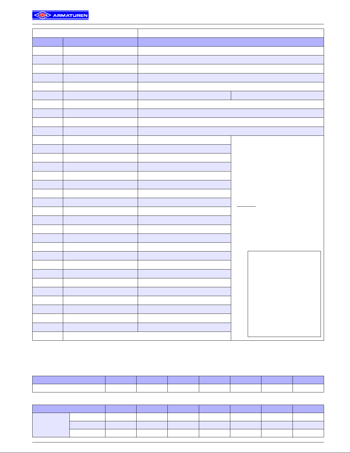
STEVI® 470 / 471 - ANSI
Figure ANSI 300 - 35.470....90 / 35.471....90
Pos. Description Material codes
1 Body SA216 WCB
2 Seat ring * AISI 420
3 Plug * AISI 420
4 Straight pin * AISI 302
5 Stem * AISI 420
6 Mounting bonnet 1“ - 2“: SA 105 3“ - 8“: SA 216 WCB
7 Guide bushing AISI 420
8 Gasket * CrNi laminated both sides with pure graphite
9 Studs SA 193 B7
10 Hexagon nuts SA 194 2H
11 V-ring unit * PTFE
13 Washer * SA 240 Gr. 304
14 Spring * AISI 302
15 Guide band * PTFE 25% C
17 Scraper* PTFE
18 Stem guide * AISI 303
19 Packing box flange SA 105
20 Studs SA 193 B8 Cl.2
21 Hexagon nuts SA 194 8/8A
22.1 Bellows housing SA 216 WCB
22.2 Mounting bonnet SA 216 WCB
22.3 Stem- / Bellows unit* AISI 321
22.4 Guide bushing AISI 420
22.5 Guide bushing AISI 420
22.6 Gasket * CrNi laminated both sides with pure graphite
22.7 Studs SA 193 B7
22.8 Hexagon nuts SA 194 2H
22.10 Packing ring * Pure graphite
22.12 Washer * SA 240 Gr. 304
22.17 Screw joint * AISI 303
25 Packing spacer * AISI 420
26 Packing ring * PTFE or pure graphite
* Spare parts
Please indicate when ordering:
1. Figure-No.
2. Size
3. Nominal pressure (PN)
4. Body material
5. Plug design
6. Cv-value
7. Stem sealing
8. Actuator
9. Special execution / accessories
Example:
Figure 35.470; size 4“;
nominal press. ANSI 300;
body material cast steel;
parabolic plug; Cv 185;
stem sealing PTFE-V-ring unit;
ARI-PREMIO 1124 lbf.
Dimensions in inch (in)
1 in =^25.4 mm
Weights in pound (lb)
1 lb =^0.45 kg
Pressures in psig (gauge)
1 psi =^0.07 bar / 1 bar =^14.5 psi
Cv in US gal/min
Cv 1 =^Kvs 0.86
1 lbf =^4.45 N
1 ft lbf =^1.36 Nm
Parts
Valve dimensions Face to face length Form RF acc. to ANSI / ISA - S75.03-1992 (Face to face lengthes for flanges Form RTJ on request.)
Size 1“ 1 1/2“ 2“ 3“ 4“ 6“ 8“
L (Fig. 470/471-ANSI) (in) 7.75 9.25 10.5 12.5 14.5 18.62 22.38
Flange dimensions Flanges acc. to ANSI B16.5
Size 1“ 1 1/2“ 2“ 3“ 4“ 6“ 8“
ANSI 300
(Fig. 470/471 ANSI)
Edition 10/04 - Data subject to alteration
∅ D (in) 4.88 6.12 6.5 8.25 10 12.5 15.0
∅ K (in) 3.5 4.5 5.0 6.62 7.88 10.62 13.0
n x ∅ d1 (in) 4 x 0.75 4 x 0.88 8 x 0.75 8 x 0.88 8 x 0.88 12 x 0.88 12 x 1.0
12
Page 13
Technical data of the valve
STEVI® 470 / 471 - ANSI
Technical data / Selection of flow restrictors / Pressure-temperature-ratings
Type: Control valve Fig. 470/471 - ANSI
Size inch 1“; 1
Nominal pressure: ANSI 300
Connections:
Stem sealing:
Body material:
Plug design:
Flanges acc.to ANSI B16.5
Standard: Form RF
Option: Form RTJ
Fig. 470 - ANSI
• PTFE-V-ring unit +14°F up to +428°F
• PTFE-packing +14°F up to +482°F
• Pure graphite-packing +14°F up to +842°F
Fig. 471 - ANSI
• Stainless steel bellows seal
(for restricted pressure range) -76°F up to +842°F
SA 216 WCB ANSI 300 Fig. 35.470....90
Standard:
• Parabolic plug (1“-6“), metal seat
• V-port plug (8“), metal seat
Special designs:
• Parabolic plug with PTFE soft seat (max. 392°F)
• Perforated plug, metal seat
• Parabolic pressure balanced plug (or perforated
plug), metal seat; Material of piston seal: PTFE
with stainless steel spring (
1/2“; 2“; 3“; 4“; 6“; 8“
max. 392°F
Fig. 35.471....90
)
Guiding:
Flow characteristic:
Rangeability:
Shut off class:
Selection of possible
applications:
• Parabolic plug: post guiding
• Perforated / V-port plug: post and port guiding
Linear or equal percentage
(from Cv 116 modified equal percentage)
• 50 : 1 on parabolic plug (1“-6“)
• 30 : 1 on parabolic plug /
perforated plug / V-port plug (8“)
• Metal seat - Leakage class IV
acc. to ANSI / FCI 70-2
• Soft seat - Leakage class VI
acc. to ANSI / FCI 70-2
(from Cv 1.2)
Fig. 470 - ANSI Fig. 471 - ANSI
• Cooling water • Refrigerant
• Cooling brine • Cooling water
• Warm water • Warm water
• Hot water • Hot water
• Steam • Heat transfer oil
• Gas • Steam
• Gas
- other applications on request -
Technical data for actuator refer to corresponding actuator data sheets.
Selection of flow restrictors
Parabolic plug
with post guiding
(Standard on 1“-6“)
Seat-∅
in
≤ 1.26 580 0.71-5.91 740
1.57-1.97 435
2.56 217 2.56-3.15 435
3.15 116
3.94 58 3.94 362
4.92-5.91 29 4.92-5.91 217
∆ Ps = max. differential pressure drop
Pressure-temperature-ratings Observe regulations
acc. to ASME B16.34
Material Class -20°F up to 100°F 200°F 300°F 400°F 500°F 600°F 650°F 700°F 750°F 800°F
470-ANSI ANSI 300 740 psi 675 psi 655 psi 635 psi 600 psi 550 psi 535 psi 535 psi 505 psi 410 psi
471-ANSI
ANSI 300
restricted
∆ Ps
psi
Temperature
580 psi 544 psi 504 psi 436 psi 404 psi 366 psi 352 psi 343 psi 335 psi 328 psi
Seat-∅
V-port plug
with post and port guiding
(Standard on 8“)
in
7.87 174 7.87 435
∆ Ps
psi
Perforated plug
with post and port guiding
Seat-∅
in
∆ Ps
psi
Intermediate values for max. permissible operational pressures can be determined by linear interpolation of the given
temperature / pressure chart.
13
Edition 10/04 - Data subject to alteration
Page 14

STEVI® 470 / 471 - ANSI
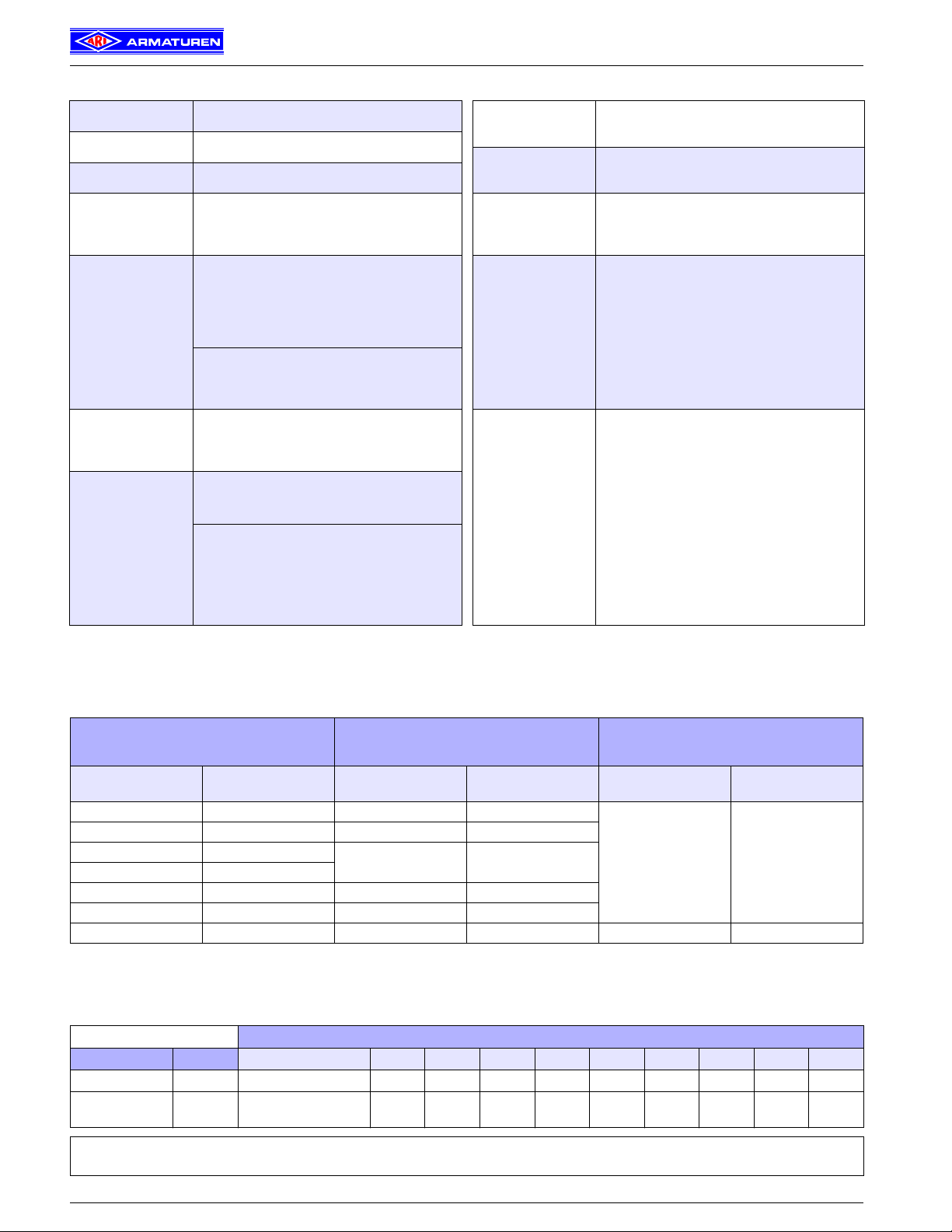
Stem sealings / Plug designs
Stem sealings
Spring loaded PTFE-V-ring unit PTFE- / pure graphite-packing Bellows seal with safety stuffing box
Plug designs
Parabolic plug with post guiding
(Standard on 1“-6“)
Perforated plug with post and port guiding
Flow direction for gas and steam to reduce
the sound level
Flow direction for liquids to reduce the
cavitation
ARI-Armaturen, USA Inc., 9363 Winkler Drive, Suite A, Houston, Texas 77017, USA, ,
Phone 713.947.3622 Fax 713.947.3635, Internet: http://www.ari-armaturen.com E-mail: scris@usa.ari-armaturen.com
14
Parabolic plug with PTFE soft seat and
Parabolic pressure balanced plug Perforated pressure balanced plug
Technology for the Future.
post guiding
GERMAN QUALITY VALVES
V-port plug with post and port guiding
(Standard on 8“)
Flow direction for gas and steam to reduce
the sound level
Flow direction for liquids to reduce the
cavitation
Edition 10/04 - Data subject to alteration
 Loading...