

Page 1

3-way control valve in mixing and diverting design
1/2“ - 6“
STEVI® 450 / 451
Electric actuator ARI-PREMIO
• Enclosure IP 65
• 2 torque switches
• 1 travel switch
• Handwheel
• Additional devices available,
e.g. potentiometer
STEVI® 450 / 451
with electric and pneumatic actuators
STEVI® 450 / 451
Pneumatic actuator DP32 - DP34
• Reversible pneumatic actuator
• Actuator with rolling diaphragm
• Air supply pressure max. 87 psi
• Stem protection by bellow
• Maintenance-free O-ring sealing
• Assembly of additional devices
acc. to DIN IEC 60534-6
Page 2
Fig. 450
Page 4
Edition 05/05 - Data subject to alteration
Fig. 451
Features:
• Compact design
• Precision guided stem
• Burnished stem
• Tapered seat ring
• Seat options available
• Reducible kvs-values
• Rangeability 30 : 1
• Guided plug
• Spring loaded PTFE-V ring packing unit
• Two-ply bellows seal
• Travel indicator
1
Page 2

(Material and Figure-No.
refer to technical data
or part list.)
495-1124 lbf: 6.5 x 5.9
2698-3372 lbf: 7.9 x 6.9
495-1124 lbf: 1.9
2698-3372 lbf: 3.5
5.1
4.7
495-1124 lbf = ∅
2698-3372 lbf = ∅
STEVI® 450 / 451
with electric actuator ARI-PREMIO
Fig. 450
Fig. 451
Diverting construction from 1 1/2“ upwards
(further information refer to page 10)
Heights and weights
Size 1/2“ 3/4“ 1“ 1 1/4“ 1 1/2“ 2“ 2 1/2“ 3“ 4“ 5“ 6“
H (in) 22.2 22.2 22.4 23.4 23.6 23.5 25 25.6 26.3 29.1 31.5
495 lbf (2,2 kN)
1124 lbf (5 kN) 25.6/26.7 27.8/29.1 30/31.3 35.7/37.7 43/45.6 51.4/54.7 66.1/70.8 80.5/86.2 117/126 163/223 223/318
...450
H (in) 28.3 29.3 29.5 29.4 30.9 31.5 32.2 34.9 37.3
2698 lbf (12 kN)
3372 lbf (15 kN)
PN16/
PN25-40 (lb)
PN16/
PN25-40 (lb)
23.1/24.3 25.4/26.7 27.6/28.8 33.3/35.3 40.6/43.2 48.9/52.2 63.7/68.3 78/83.7 115/124/ 161/221 --
38.8/40.1 44.5/46.5 51.8/54.5 60.2/63.5 75/79.6 89.3/95 126/135 172/232 232/326
H (in) 29.5 29.5 29.6 30.7 30.3 30 34.2 34.7 35.4 43 44.3
495 lbf (2,2 kN)
1124 lbf (5 kN) 32.2/33.7 34.4/36.2 37/39 42.3/44.8 52.9/56.4 60/64.2 80/86 102/110 141/152 185/247 245/342
...451
H (in) 35.6 36.6 36.2 35.9 40.1 40.6 41.3 48.9 50.2
2698 lbf (12 kN)
3372 lbf (15 kN)
PN16/
PN25-40 (lb)
PN16/
PN25-40 (lb)
29.8/31.3 32/33.7 34.6/36.6 39.9/42.3 50.5/54 57.5/61.7 77.6/83.5 99.4/107 139/150 -- --
45.9/47.8 51.1/53.6 61.7/62.3 68.8/73 88.8/94.8 111/119 150/161 194/256 254/351
Other dimensions refer to page 9.
2
Edition 10/04 - Data subject to alteration
Page 3

STEVI® 450 / 451
Closing pressures with ARI-PREMIO
max. permissible closing pressures for both seat positions on flow-to-open P2 = 0 (Observe pressure-temperature-limits on page 9)
Mixing
function
1)
Actuator
ARI-PREMIO
495 lbf
(2,2 kN)
1)
Actuator
ARI-PREMIO
1124 lbf
(5 kN)
1)
Actuator
ARI-PREMIO
2698 lbf
(12 kN)
1)
Actuator
ARI-PREMIO
3372 lbf
(15 kN)
Diverting
function
1)
Actuator
ARI-PREMIO
495 lbf
(2,2 kN)
1)
Actuator
ARI-PREMIO
1124 lbf
(5 kN)
1)
Actuator
ARI-PREMIO
2698 lbf
(12 kN)
1)
Actuator
ARI-PREMIO
3372 lbf
(15 kN)
I. Fig. 450: PTFE-V-ring unit; II. Fig. 450: Pure graphite packing; III. Fig. 451: Bellows seal
Size 1/2“ 3/4“ 1“ 1 1/4“ 1 1/2“ 2“ 2 1/2“ 3“ 4“ 5“ 6“
Seat-∅ A / B (in)
0.83/0.79 0.83/0.98 1.06/1.06 1.22/1.26 1.61/1.58 2.01/1.97 2.60/2.36 3.19/2.95 3.98/3.74 4.72/4.72 5.51/5.51
Standard Cv-values 4.6 7.3 12 18 29 46 73 116 185 289 370
Reduced Cv-values
3)
2.9 4.6 7.3 12 18 29 46 73 116 185 289
Tr av e l (in) 0.79 1.18 1.97
I. 580 521 446 314 186 116 63 38 22
Closing pressure (psi)
II. 580 488 418 294 173 107 56 34 119
III. 445 436 394 276 154 95 52 31 17
Operating time
(Operating speed 0.01 in/s)
2)
(s)
53 79
I. 580 580 580 482 308 179 115 72 49 35
Closing pressure (psi)
II. 580 580 580 469 300 172 111 69 47 33
III. 580 580 580 580 450 288 168 108 67 44 31
Operating time
(Operating speed 0.01 in/s)
2)
(s)
53 79 132
I. 580 580 468 308 196 137 100
Closing pressure (psi)
II. 580 580 462 303 193 135 98
III. 580 580 458 300 191 132 96
Operating time
(Operating speed 0.03 in/s)
2)
(s)
25 38 63
I. 580 390 249 175 127
Closing pressure (psi)
II. 580 386 246 173 126
III. 580 383 245 170 124
Operating time
(Operating speed 0.01 in/s)
2)
(s)
79 132
Size 1/2“ 3/4“ 1“ 1 1/4“ 1 1/2“ 2“ 2 1/2“ 3“ 4“ 5“ 6“
Seat-∅ A / B (in)
0.83/0.79 0.83/0.98 1.06/1.06 1.22/1.26 1.57/1.57 1.97/1.97 2.36/2.36 2.95/2.95 3.54/3.54 4.13/4.13 4.92/4.92
Standard Cv-values 4.6 7.3 12 18 16 29 52 69 110 197 231
Reduced Cv-values
3)
2.9 4.6 7.3 12 -- -- -- -- -- -- --
Tr av e l (in) 0.79 1.18
I. 372 261 223 157 194 119 78 46 30 19
Closing pressure (psi)
II. 349 244 209 147 181 111 70 41 26 17
III. 223 218 197 138 161 98 65 38 24
Operating time
(Operating speed 0.01 in/s)
2)
(s)
53 79
I. 580 580 558 397 502 318 217 136 92 65 44
Closing pressure (psi)
II. 580 580 543 387 488 309 209 131 89 62 42
III. 580 580 531 378 469 296 204 128 86 59 40
Operating time
(Operating speed 0.01 in/s)
2)
(s)
53 79
I. 580 580 580 580 564 360 248 179 125
Closing pressure (psi)
II. 580 580 580 580 556 355 245 176 123
III. 580 580 580 580 551 351 242 173 121
Operating time
(Operating speed 0.03 in/s)
2)
(s)
25 38
I. 580 456 315 228 160
Closing pressure (psi)
II. 580 451 312 225 158
III. 580 447 309 222 155
Operating time
(Operating speed 0.01 in/s)
2)
(s)
79
1)
Motor voltage: 230V 50/60Hz Special voltages: 24V 50/60Hz; 115V 50/60Hz
Technical data for actuator refer to data sheet ARI-PREMIO
2)
Indicated operating times with 50 Hz.
3)
Cv-value reducible on request (2 threaded seat rings required)
Edition 10/04 - Data subject to alteration
3
Page 4

(Material and Figure-No.
refer to technical data
or part list.)
STEVI® 450 / 451
with pneumatic actuator DP 32 - 34
Fig. 451Fig. 450
Diverting plug 1 1/2“ upwards (further information refer to page 10)
Heights and weights
Size 1/2“ 3/4“ 1“ 1 1/4“ 1 1/2“ 2“ 2 1/2“ 3“ 4“ 5“ 6“
∅ A (in) 9.84
H (in) 17.7 17.7 17.9 18.9 19.1 19.1 20.5 21.1 21.9
...450
DP 32
DP 33
DP 34
Other dimensions refer to page 9.
PN16/PN25-40 (lb)
H (in) 25.0 25.0 25.2 26.2 25.8 25.6 29.7 30.2 30.9
...451
PN16/PN25-40 (lb)
∅ A (in) 11.81
H (in) 19.9 19.9 20.0 21.1 21.3 21.2 22.6 23.3 24.0 25.9 28.3
...450
PN16/PN25-40 (lb)
H (in) 27.2 27.2 27.3 28.3 28.0 27.7 31.9 32.4 33.0 39.8 41.1
...451
PN16/PN25-40 (lb)
∅ A (in) 15.94
H (in) 28.0 28.6 29.3 30.4 32.8
...450
PN16/PN25-40 (lb)
H (in) 37.2 37.7 38.3 44.4 45.7
...451
PN16/PN25-40 (lb)
31.1/32.2 33.3/34.6 35.5/36.6 41.2/43.2 48.5/51.2 56.9/60.2 71.6/76.3 86.0/91.7 124/132
37.7/39.2 39.9/41.7 42.5/44.5 47.8/50.3 58.4/62.0 65.5/69.7 85.5/91.5 107/115 146/159
44.3/45.4 46.5/47.8 48.7/50.0 54.5/56.4 61.7/64.4 70.1/73.4 84.9/89.5 99.2/105 137/146 181/243 243/337
50.9/52.5 53.1/54.9 55.8/57.8 61.1/63.5 71.6/75.2 78.7/82.9 98.8/105 121/129 159/172 203/265 265/359
151/156 165/171 203/212 247/309 309/403
165/171 187/195 225/238
269
/331 331/426
4
Edition 10/04 - Data subject to alteration
Page 5

STEVI® 450 / 451
Closing pressures with DP
max. permissible closing pressures for both seat positions
on flow-to-open P2 = 0
(Observe pressure-temperature-limits on page 9)
Spring closes port A -> AB or Spring closes port B -> AB
Mixing
function
Size 1/2“ 3/4“ 1“ 1 1/4“ 1 1/2“ 2“ 2 1/2“ 3“ 4“ 5“ 6“
Standard Cv-values
Reduced Cv-values
2)
4.6 7.3 12 18 29 46 73 116 185 289 370
2.9 4.6 7.3 12 18 29 46 73 116 185 289
Tr av e l (in) 0.79 1.18 1.97
I. 80 47 38 21
3 - 15
17
II. 33 14
III.
I. 270 183 155 105 57 32
6 - 17 23
II. 224 150 126 84 44 23
III. 125 116 102 67 25
Actuator
DP 32
12 - 35 46
Control signal (psi)
22 - 36 58
Air supply pressure min. (psi)
I. 580 455 389 273 160 99
II. 580 422 360 252 147 91
III. 382 373 336 235 128 78
I. 580 580 567 341 217
II. 580 580 547 329 209
III. 580 580 580 530 310 197
I. 580 471 302
29 - 48 77
II. 580 458 293
III. 580 439 281
Actuator
DP 33
3 - 15
6 - 17 23
12 - 35 46
22 - 44 65
Control signal (psi)
25 - 39 64
c)
192
c)
146
a)
72
496c)344c)293c)204c)118
c)
449
277a)268a)241a)166
a)
580
580a)580a)580a)451a)270a)171
17
I.
II.
III.
I.
II.
III.
I.
II.
III. 580 580 580 434 251 158 90 57 34
I. 214 139 87
II. 207 134 84
III. 203 132 82
Air supply pressure min. (psi)
I.
II.
128c)107
c)
94
a)
63
311c)265c)184c)105
580a)580a)472a)283a)179
c)
70
c)
78
54
50
a)
33
580
580a)580a)412
c)
c)
a)
a)
a)
c)
35
23
86
18
c)
c)
72
c)
63
a)
51
580a)421
c)
c)
36 21
c)
30 16
a)
a)
26
a)
101 64 38
a)
94 59 36
a)
a)
III. 580 580 400
I. (580) 295 192 121
87
II. (573) 288 188 119
(87)
III. (561) 284 185 117
17
I.
II.
III.
I.
II.
III.
367
30
26
102
95
91
b)
b)
e)
b)
b)
d)
I. 232 150 94 65 46
II. 225 146 92 63 45
III.
I. (580) (431) (279) 134 98
65
II. (580) (426) (273) 132 96
(74)
III. 129 94
I. (495) (317) 184 134
87
II. (491) (315) 182 132
(87)
221
b)
Actuator
DP 34
29 - 58
(3 - 54)
3 - 15
6 - 17 23
12 - 35 46
Control signal (psi)
22 - 44
(31 - 44)
29 - 58
(35 - 52)
Air supply pressure min. (psi)
III. 179 130
I. Fig. 450: PTFE-V-ring unit; II. Fig. 450: Pure graphite-packing; III. Fig. 451: Bellows seal
Air supply pressure max. of pneumatic actuators DP: 87 psi
Air supply pressure max. limit of control valve: a) 73 psi b) 65 psi c) 58 psi d) 51 psi e) 44 psi
Higher closing pressures for Size 5“-6“ in connection with DP34T on request!
2)
Cv-value reducible on request (2 threaded seat rings required)
21
17
14
64
60
57
143
b)
b)
e)
b)
b)
d)
b)
b)
d)
b)
25 17
23 16
a)
21
60 43
39
36
34
b)
90
Edition 10/04 - Data subject to alteration
5
Page 6

STEVI® 450 / 451
Closing pressures with DP
max. permissible closing pressures for both seat positions
on flow-to-open P2 = 0
(Observe pressure-temperature-limits on page 9)
Spring closes port A -> AB or Spring closes port B -> AB
Diverting
function
Size 1/2“ 3/4“ 1“ 1 1/4“ 1 1/2“ 2“ 2 1/2“ 3“ 4“ 5“ 6“
Standard Cv-values
Reduced Cv-values
2)
4.6 7.3 12 18 16 29 52 69 110 197 231
2.9 4.6 7.3 12 -- -- -- -- -- -- --
Tr av e l (in) 0.79 1.18
I. 40 24 19
3 - 15
17
II. 17
III.
I. 135 92 77 52 60 33 17.4
6 - 17 23
II. 112 72 63 42 47 25
III. 62 58 51 33 27
Actuator
DP 32
12 - 35 46
Control signal (psi)
22 - 36 58
Air supply pressure min. (psi)
I. 326 227 195 136 168 102 66 39 24 16
II. 302 211 180 126 154 94 58 34 21
III. 191 187 168 118 135 81 53 30 19
I. 580 465 399 284 356 224
II. 580 449 385 273 343 215
III. 416 412 373 265 323 203
I. 580 546 389 491 310
29 - 48 77
II. 580 531 378 477 302
III. 577 573 519 370 458 289
Actuator
DP 33
3 - 15
6 - 17 23
12 - 35 46
22 - 44 65
Control signal (psi)
25 - 39 64
c)
96
c)
73
a)
36
248c)172c)147c)102c)124
225
139a)134a)120
551
528a)372a)319a)226a)282a)176
17
I.
II.
III.
I.
II.
III.
I.
II.
III. 344 339 307 217 262 163 111 67 44 28 18
I. 259 163 111 79 54
II. 251 158 108 76 52
III. 246 155 105 73 50
I.
Air supply pressure min. (psi)
580
II.
580a)580a)580a)527a)580a)424
c)
64
c)
47
a)
32
c)
155c)132
a)
388a)333a)236a)295a)185
a)
580a)580a)537a)580a)433
c)
54
c)
39
a)
27
c)
35
c)
25
a)
16
c)
c)
92
a)
110
a)
83
c)
38
c)
25
a)
91
c)
19
c)
c)
74
c)
66
53
46 26 15
c)
38 21
a)
a)
33
a)
124 76 50 34 23
a)
116 71 47 32 20
a)
a)
III. 580 580 580 518 580 412
I. (580) (580) 356 225 155 111 77
87
II. (580) (580) 348 220 151 108 74
(87)
III. (580) (577) 343 217 149 104 72
17.4
I.
II.
III.
I.
II.
III.
47
39
34
125
117
112
b)
b)
e)
b)
b)
d)
I. 280 177 121 86 59
II. 272 172 117 83 57
III.
267
b)
I. 580 503 348 252 177
II. 580 498 345 249 175
III. 246 172
Actuator
DP 34
29 - 58
(33 - 54)
3 - 15
6 - 17 23
12- 35 46
Control signal (psi)
31 - 44 5
Air supply pressure min. (psi)
I. 578 401 290 204
35 - 52 6
II. 573 397 287 202
III. 284 199
I. Fig. 450: PTFE-V-ring unit II. Fig. 450: Pure graphite-packing III. Fig. 451: Bellows seal
Air supply pressure max. of pneumatic actuators DP: 87 psi
Air supply pressure max. limit of control valve: a) 73 psi b) 65 psi c) 58 psi d) 51 psi e) 44 psi
Higher closing pressures for Size 5“-6“ with DP34T on request!
2)
Cv-value reducible on request (2 threaded seat rings required)
a)
18
b)
26
21
18
76
71
68
16
b)
e)
b)
51
b)
47
d)
45
169b)115
b)
b)
b)
d)
b)
35 23
32 21
a)
28
80 55
a)
18
6
Edition 10/04 - Data subject to alteration
Page 7
STEVI® 450 / 451
Cv-value chart
Size 1/2“ 3/4“ 1“ 1 1/4“ 1 1/2“ 2“ 2 1/2“ 3“ 4“ 5“ 6“
Cv Seat-∅ A / B (in)
0.83/0.79
2.9
0.83/0.79 0.83/0.98
4.6
0.83/0.98 1.06/1.06
1.06/1.06 1.22/1.26
1.22/1.26 1.61/1.57
1.61/1.57 2.01/1.97
2.01/1.97
2.60/2.36
2.60/2.36 3.19/2.95
3.19/2.95 3.98/3.74
3.98/3.74
4.72/4.72
4.72/4.72 5.51/5.51
0.83/0.98 1.06/1.06
1.06/1.06 1.22/1.26
1.57/1.57
1.22/1.26
1.97/1.97
2.36/2.36
2.95/2.95
3.54/3.54
4.13/4.13
Mixing valve
Diverting valve
7.3
12
18
29
46
46
73
116
185
185
289
370
0.83/0.79
2.9
0.83/0.79 0.83/0.98
4.6
7.3
12
16
18
29
52
69
110
197
231
Cv-value chart
Travel
(in)
0.79
1.18
1.97
5.51/5.51
0.79
1.18
4.92/4.92
Edition 10/04 - Data subject to alteration
7
Page 8

STEVI® 450 / 451
Parts
Figure
PN16 - 12.4504) / 12.451
PN16 - 22.450 / 22.451
4)
PN25 - 23.450
4)
/ 23.451
PN25 - 34.450 / 34.451
4)
PN40 - 35.450 / 35.451 PN40 - 55.450
Pos. Description Material codes
1 Body SA 278 Class 40 SA 395 SA 216 WCB SA 351 CF 8
1.2 Seat ring AISI 420 --
2 Seat ring * AISI 420 AISI 316 TI
3 Plug * AISI 420 AISI 316 TI
4 Self-locking nut * AISI 316 TI
5 Stem * AISI 420 AISI 316 TI
6 Straight pin * AISI 302 AISI 321
7 Mounting bonnet SA 395 SA 216 WCB SA 351 CF 8
8 Guide bushing AISI 420 (hardened) AISI 316 TI
9 Gasket * CrNi laminated both sides with pure graphite
10 Studs AISI 1035 / 1038 AISI 316
11 Hexagon nuts AISI 1035 AISI 316
12 V-ring unit * PTFE
13 Packing ring * PTFE or pure graphite
14 Washer * SA 240 Gr. 304
15 Spring * AISI 302
16 Bushing * Reinforced PTFE
17 Sealing ring * Soft iron / Copper AISI 316 TI
18 Scraper * Reinforced PTFE
19 Screw joint* AISI 303
20.1 Bellows housing SA 395 SA 216 WCB SA 351 CF 8
20.2 Mounting bonnet SA 395 SA 216 WCB SA 351 CF 8
20.3 Stem- / Bellows unit * AISI 420 / SA 182 F 321 AISI 316 TI
20.4 Guide bushing AISI 420 (hardened) AISI 316 TI
20.5 Guide bushing AISI 420 (hardened) AISI 316 TI
20.6 Gasket * CrNi lam. both sides with pure graphite
20.7 Studs AISI 1035 / 1038 AISI 316
20.8 Hexagon nuts AISI 1035 AISI 316
20.10 Packing ring * Pure graphite
20.12 Washer * SA 240 Gr. 304
20.17 Screw joint * AISI 303
31 Plug * AISI 420 AISI 316 TI
32 Distance bushing * SA 240 Gr. 304
37 Stem adapter * AISI 420 AISI 316 TI
38 Stem adapter * AISI 420 AISI 316 TI
40 Plug * AISI 420 AISI 316 TI
41 Stem adapter * AISI 420 AISI 316 TI
42 Screw joint * AISI 303
* Spare parts
4)
/ 55.451
4)
up to Size 4“
4)
Please indicate when ordering:
1. Figure-No. 4. Body material 7. Stem sealing
2. Nominal diameter (DN) 5. Plug design 8. Actuator
3. Nominal pressure (PN) 6. Cv-value 9. Special version / accessories
Example:
Figure 35.450; size 4“; nominal press. PN 40 bar; body material cast steel; mixing construction;
Cv 185; stem sealing PTFE-V-ring unit; ARI-PREMIO 1124 lbf (5 kN).
Edition 10/04 - Data subject to alteration
Dimensions in inch (in)
1 in =^25.4 mm
Weights in pound (lb)
1 lb =^0.45 kg
Pressures in psig (gauge)
1 psi =^0.07 bar / 1 bar =^14.5 psi
Cv in US gal/min
Cv 1 =^Kvs 0.86
1 lbf =^4.45 N
1 ft lbf =^1.36 Nm
8
Page 9

Technical data of the valve
Type: Control valve Fig. 450-451
STEVI® 450 / 451
Technical data / Pressure-temperature-ratings / Dimensions
Plug design: Parabolic plug / V-port plug
Size: Size 1/2“ - 6“
Nominal pressure: PN 16, PN 25, PN 40
Fig. 450
• PTFE-V-ring unit +14°F up to +428°F
• PTFE-packing +14°F up to +482°F
Stem sealing:
Body material:
Technical data for actuator refer to corresponding actuator data sheets.
Pressure-temperature-ratings acc. to DIN EN1092-1 / -2 Observe regulations
acc. to DIN EN 1092-2
Material PN
SA 278 Cl. 40 16 bar --- 232 psi 208 psi 185 psi 162 psi 139 psi --- --- ---
SA 395
• Pure graphite-packing +14°F up to +842°F
Fig. 451
• Stainless steel bellows seal
with safety stuffing box -76°F up to +842°F
Cast iron (to 4“) PN16 Fig. 12.450 / 12.451
Spheroidal graph. iron PN16 Fig. 22.450 / 22.451
Sph. graph. iron (to 4“) PN25 Fig. 23.450 / 23.451
Cast steel PN25 Fig. 34.450 / 34.451
Cast steel PN40 Fig. 35.450 / 35.451
Stainless steel (to 4“) PN40 Fig. 55.450 / 55.451
Other materials and executions on request
Temperature
-76°F up to <14°F*
16 bar on request 232 psi 225 psi 213 psi 201 psi 186 psi 162 psi --- ---
25 bar on request 362 psi 352 psi 333 psi 316 psi 290 psi 254 psi --- ---
14°F up to 248°F 302°F 392°F 482°F 572°F 662°F 752°F 842°F
Guiding: Stem and port guiding
Flow characteristic: linear
Rangeability: 30 : 1
Shut off classes:
Selection of possible
applications
:
Metal seat - Leakage class IV
acc. to ANSI / FCI 70-2
Fig. 450 Fig. 451
• Cooling water • Refrigerant
• Cooling brine • Cooling water
• Warm water • Warm water
• Hot water • Hot water
• Steam • Heat transfer oil
• Gas • Steam
- other applications on request -
• Gas
acc. to DIN EN 1092-1
Material PN
SA 216 WCB
SA 351 CF 8 M 40 bar 580 psi 580 psi 540 psi 490 psi 451 psi 425 psi 400 psi 387 psi 371 psi --
Intermediate values for max. permissible operational pressures can be determined by linear interpolation of the given
temperature / pressure chart.
* Valve with extended bonnet, studs and nuts made of AISI 316 required (at temperatures below -14°F)
Valve dimensions Face to face length FTF series 1 according to DIN EN 558-1 (DIN 3202-1 series F1)
Size 1/2“ 3/4“ 1“ 1 1/4“ 1 1/2“ 2“ 2 1/2“ 3“ 4“ 5“ 6“ 8“ 10“
L (in) 5.12 5.91 6.30 7.09 7.87 9.06 11.42 12.20 13.78 15.75 18.90 23.62 28.74
H2 (in) 2.56 2.76 2.95 3.15 3.54 3.94 4.72 5.12 5.91 7.87 8.27 14.96 17.32
Flange dimensions Flanges acc. to DIN EN 1092-1 (Flangeholes/-thickness tolerances acc. to DIN 2533 / 2544 / 2545)
Size 1/2“ 3/4“ 1“ 1 1/4“ 1 1/2“ 2“ 2 1/2“ 3“ 4“ 5“ 6“ 8“ 10“
PN 16 bar
PN 25 bar
PN 40 bar
25 bar 271 psi 362 psi 338 psi 314 psi 281 psi 258 psi 233 psi 217 psi 209 psi 201 psi
40 bar 435 psi 580 psi 541 psi 503 psi 438 psi 412 psi 374 psi 348 psi 335 psi 322 psi
∅ D (in) 3.74 4.13 4.53 5.51 5.91 6.50 7.28 7.87 8.66 9.84 11.22 13.39 15.94
∅ K (in) 2.56 2.95 3.35 3.94 4.33 4.92 5.71 6.30 7.09 8.27 9.45 11.61 13.98
n x ∅ d1 (in) 4x0.55 4x0.55 4x0.55 4x0.71 4x0.71 4x0.71 4x0.71 8x0.71 8x0.71 8x0.71 8x0.87 12x0.87 12x1.05
∅ D (in) 3.74 4.13 4.53 5.51 5.91 6.50 7.28 7.87 9.25 10.63 11.81 14.17 16.73
∅ K (in) 2.56 2.95 3.35 3.94 4.33 4.92 5.71 6.30 7.48 8.66 9.84 12.20 14.57
n x ∅ d1 (in) 4x0.55 4x0.55 4x0.55 4x0.71 4x0.71 4x0.71 8x0.71 8x0.71 8x0.87 8x1.02 8x1.02 12x1.02 12x1.18
∅ D (in) 3.74 4.13 4.53 5.51 5.91 6.50 7.28 7.87 9.25 10.63 11.81 14.76 17.72
∅ K (in) 2.56 2.95 3.35 3.94 4.33 4.92 5.71 6.30 7.48 8.66 9.84 12.60 15.16
n x ∅ d1 (in) 4x0.55 4x0.55 4x0.55 4x0.71 4x0.71 4x0.71 8x0.71 8x0.71 8x0.87 8x1.02 8x1.02 12x1.18 12x1.3
Temperature
-76°F up to <14°F*
14°F up to 122°F 212°F 302°F 392°F 482°F 572°F 662°F 752°F 842°F
9
Edition 05/05 - Data subject to alteration
Page 10
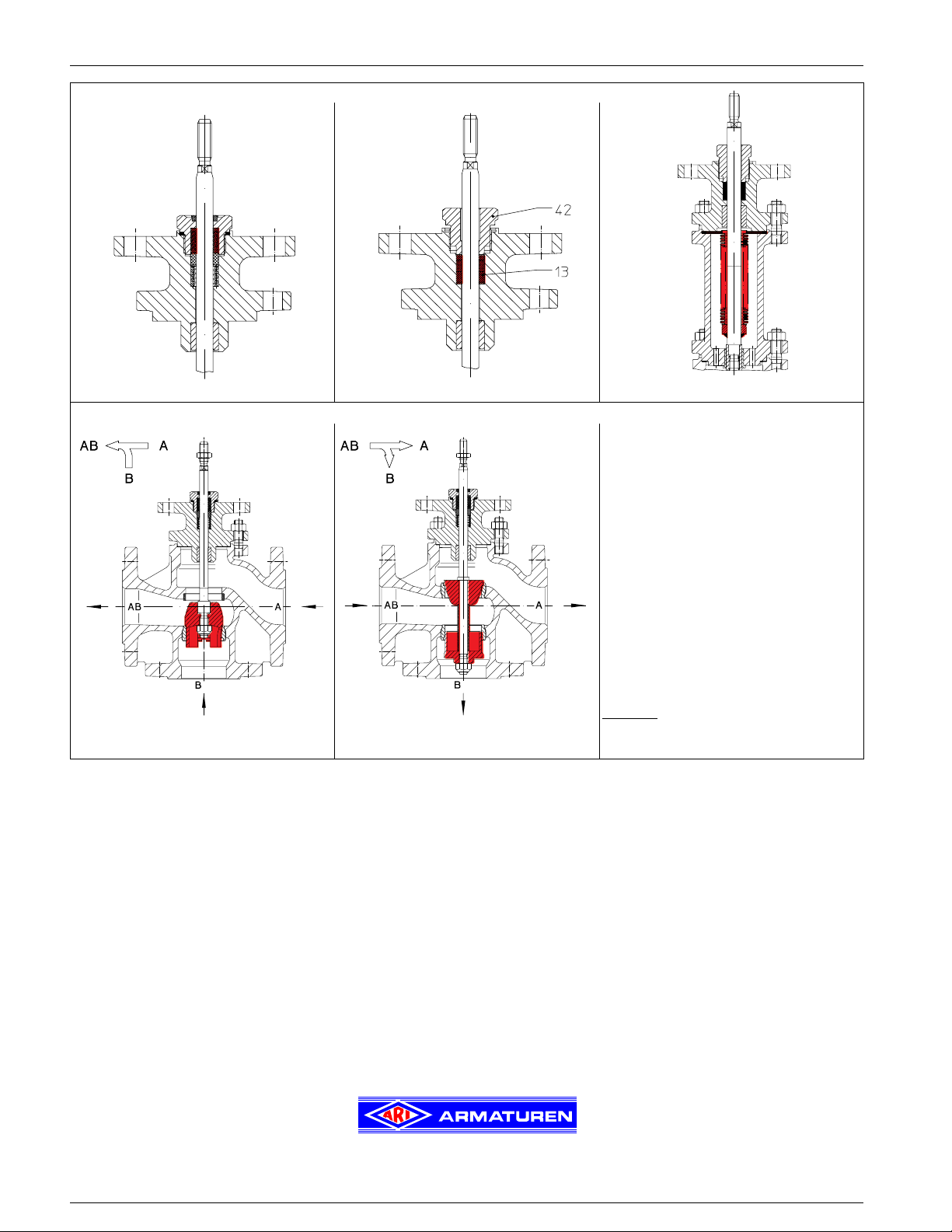
Stem sealings
Operating mode
Design with mixing plug Size 1/2“ - 6“ Design with diverting plug Size 1 1/2“ - 6“
(Attention: reduced Cv-values)
STEVI® 450 / 451
Stem sealings / Operating mode
Bellows seal with safety stuffing boxSpring loaded PTFE-V-ring unit PTFE- / pure graphite-packing
ARI-Control valves are suitable for use with pneu-
matic or electric actuators.
According to the application two different variations
are possible (see drawings on the left)
Design with mixing plug as standard.
Select when the valve is used for mixing service (2
inlets, 1 outlet).
1/2“-11/4“ with mixing plug can also be used
Size
for diverting service (1 inlet, 2 outlets).
In exceptions the design with mixing plug can also
be used in diverting service for Size ≥ 1
small closing pressures are possible.
Design with diverting plug will be used
exclusively for diverting service.
1/2“. Only
10
Technology for the Future.
GERMAN QUALITY VALVES
Phone 713.947.3622 Fax 713.947.3635, Internet: http://www.ari-armaturen.com E-mail: scris@usa.ari-armaturen.com
ARI-Armaturen, USA Inc., 9363 Winkler Drive, Suite A, Houston, Texas 77017, USA, ,
Edition 10/04 - Data subject to alteration
 Loading...