

Page 1
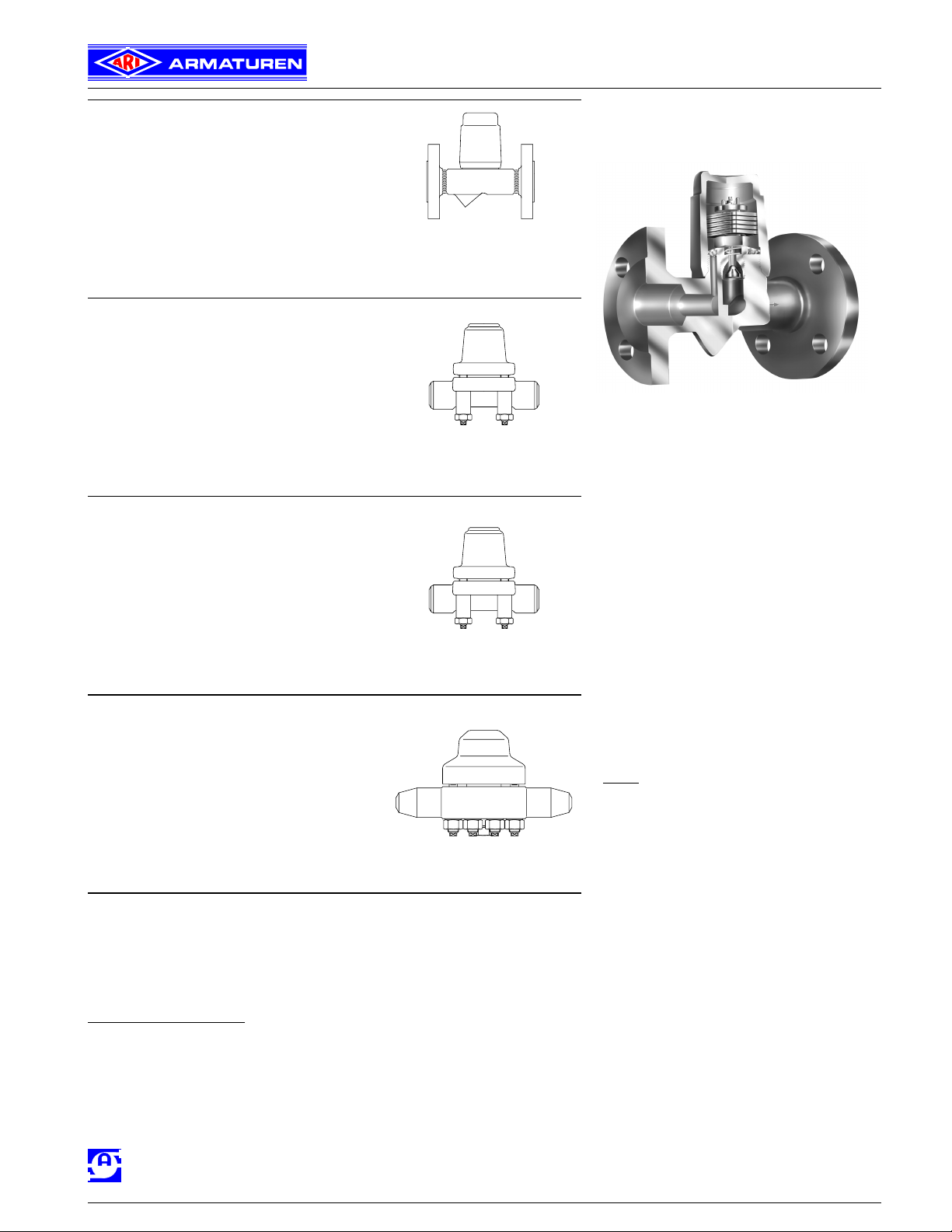
Bimetallic steam trap
ANSI 150 / 300
- with flanges (Series 600/601....1)
- with threaded ends (Series 600/601....2)
- with socket weld ends (Series 600/601....3)
- with butt weld ends (Series 600/601....4)
High pressure Bimetallic steam trap
ANSI 400 / 600
- with flanges (Series 600/601....1)
- with socket weld ends (Series 600/601....3)
- with butt weld ends (Series 600/601....4)
Forged steel
High temperature steel
Series 600Page 2
High temperature steel
Series 600 1
CONA® B
Bimetallic steam traps
Fig. 600...1
1/2“-1“ Page 4
1/2“-2“ Page 6
High pressure Bimetallic steam trap
ANSI 900 / 1500
- with flanges (Series 600/601....1)
- with socket weld ends (Series 600/601....3)
- with butt weld ends (Series 600/601....4)
High temperature steel
Series 600 Page 8
High pressure Bimetallic steam trap
ANSI 2500
- with flanges (Series 600/601....1)
- with socket weld ends (Series 600/601....3)
- with butt weld ends (Series 600/601....4)
High temperature steel
Series 600 Page 10
Selection criteria:
- Steam pressure - Type of connection
- Back pressure - Controller
- Quantity of condensate - Material
- Size / Class - Place of service or type of steam consumer
Example for order data:
Features:
• For the discharge of condensate sub-cooled
up to 30 K / 54 °F
• Automatic ventilation during start up and operation of
the plant
• Robust and insensitive to water hammer
• Integrated check valve
Design:
•
• Optimized design for quick installation
(ANSI 150 / 300, size 1/2“-1“)
• Machined sealing surface (body to cap)
(ANSI 150 / 300, size
• Installation with cover facing up-or sidewards
• Subcooling of condensate is continuously adjustable
(observe the operation instructions)
• The exchange of the controller is possible without dis-
turbing the pipe connections
• CRN approved
- with integrated strainer - Series 600
- with outside strainer - Series 601 (Y)
1/2“-1“)
45.600 / type of connection / size / controller
=> Bimetallic steam trap CONA
SA182F1, ANSI 300, with flanged connection,
Size 1“, Controller R22, Face-to-face dimension 6.30 inch
®
AWH
HALLE
WERK HALLE GMBH
a member of the ARI-group
Edition 09/05 - Data subject to alteration 1
ARMATUREN-
®
B - Figure 45.600,
Page 2
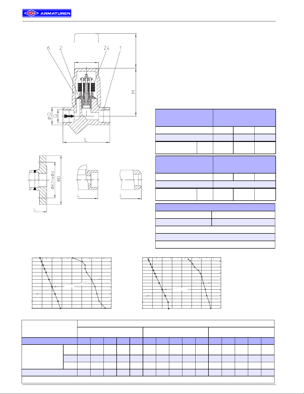
Series 600 - ANSI 150 / 300, size 1/2“ - 2“
Bimetallic steam trap made of forged steel, high temperature steel
• Bimetallic steam trap with corrosion resistant and waterhammerproof
bimetallic controller
• Automatic ventilation during start up and operation of the plant
2.76“
Hex.1.97“
Fig. 600/601....2 threaded ends
• Integrated check valve
• with integrated strainer - Series 600
with outside strainer - Series 601 (Y)
• Optimized design for quick installation
• Installation with cover facing up-or sidewards
• Subcooling of condensate is continuously adjustable
(observe the operation instructions)
• Service advantage machined mating cap to body
ANSI 150 Fig. 42.600/601
ANSI 300 Fig. 45.600/601
SA 105
Max. temperature (°F) ANSI 150 n.a. n.a. 437
Max. temperature (°F) ANSI 300 771 800 800
Controller unit
permissible ∆P (psi)
Sizes
1/2“ to 2“
Operating limits
R32
464
CONA® B
R22
319
R13
189
ANSI 150 Fig. 82.600/601
ANSI 300 Fig. 85.600/601
Operating limits
SA 182 F1
Max. temperature (°F) ANSI 150 n.a. n.a. 437
Max. temperature (°F) ANSI 300 875
Controller unit
permissible ∆P (psi)
Sizes
1/2“ to 2“
R32
464
R22
319
R13
189
Types of connection
Fig. 600/601....1
flanged
Fig. 600/601....3
socket welded ends
Fig. 600/601....4
butt welded ends
Flanges ....1 ANSI 150 RF and 300 RF
Threaded ends ....2 R- and NPT-thread
Socket weld ends ....3
Butt weld ends ....4
010203040
800
700
600
˚F
500
ure
t
400
pera
m
Te
300
200
100
0 200 400 600
Working Pressures barg
CL150
Working Pressures psig ; Material: SA105
(Operating Limits ASME B16.34 STANDARD CLASS)
Steam saturation curve
CL300
Steam
Water
50
400
350
300
˚C
250
ure
200
perat
m
Te
150
100
50
800
010203040
875
800
700
600
˚F
500
ture
ra
400
Tempe
300
200
100
0 200 400 600
Other types of connection on request.
Working Pressures barg
CL300
CL150
Working Pressures psig ; Material: SA182F1
(Operating Limits ASME B16.34 STANDARD CLASS)
a
Ste
ion curve
t
a
ur
t
m sa
Steam
Water
50
450
400
350
300
˚C
ure
t
250
200
Tempera
150
100
50
800
Types of connection
Dimensions and weights
Flanges
Threaded ends
Socket weld ends
Butt weld ends
Size 1/2“ 3/4“ 1“ 11/2“ 2“ 1/2“ 3/4“ 1“ 1 1/2“ 2“ 1/2“ 3/4“ 1“ 1 1/2“ 2“
6.3/
8.27 9.84 9.84 9.84 9.84 9.84
5.12
Dimensions (in)
L * 5.91 5.91 6.30 9.06 9.06 3.74 3.74 3.74
H 3.86 3.86 3.86 5.67 5.67 3.86 3.86 4.06 5.67 5.67 3.86 3.86 3.86 5.67 5.67
H1 2.44 2.44 2.44 2.68 2.68 2.44 2.44 2.17 2.68 2.68 2.44 2.44 2.44 2.68 2.68
Weight approximate (lb) 7.1 8.2 9.3 24.9 26.7 3.7 3.5 4.6 17.6 17.6 4.9 5.1 5.3 19.6 21.6
* other face-to-face dimensions on request For standard flange dimensions refer to page 12
2 Edition 10/04 - Data subject to alteration
Page 3

Series 600 - ANSI 150 / 300, size 1/2“ - 2“
Parts
Pos. Description
1 Body SA 105 SA 182 F1
2 Strainer * SA 240 Gr. 304 SA 240 Gr. 304
6 Screw cap SA 105 SA 182 F1
7 (Y) Strainer screen * SA 240 Gr. 304 SA 240 Gr. 304
8 (Y) Strainer plug * SA182 F321 SA182 F321
24 Controller * corrosion resist. bimetal TB 102 / 85
42 Sealing ring for plug* R-Cu99
43 Plug * 1035, 1038
46 Blow down valve cpl. AISI 303 AISI 303
* Spare parts Design parameters acc. ASME B16.34
Capacity chart
Material codes
ASTM / AISI
1)
Capacity chart
The capacity chart shows the maximum flow for controller R13, R22
and R32 at factory setting.
Curve 1
Maximum flow rate of hot condensate at approx. 10 K / 18°F below
saturation temperature.
Curve 2
Maximum flow rate of sub-cooled condensate approx. 30 K / 54°F
below saturation temperature.
Curve 3
Maximum flow rate of condensate at about 68˚F (cold start-up).
SA 182 F321
1)
CONA® B
1)
with metric screw-thread
The condensate-temperature determines the opening of the controller. The capacity increases with sub-cooling of the condensate.
3.54“
0.95“
Special design:
0.39“
Plug in the screw cap
Series 603 (Y)
Edition 10/04- Data subject to alteration 3
Series 601 (Y) with outside strainer
Optional: with blow down valve
Page 4
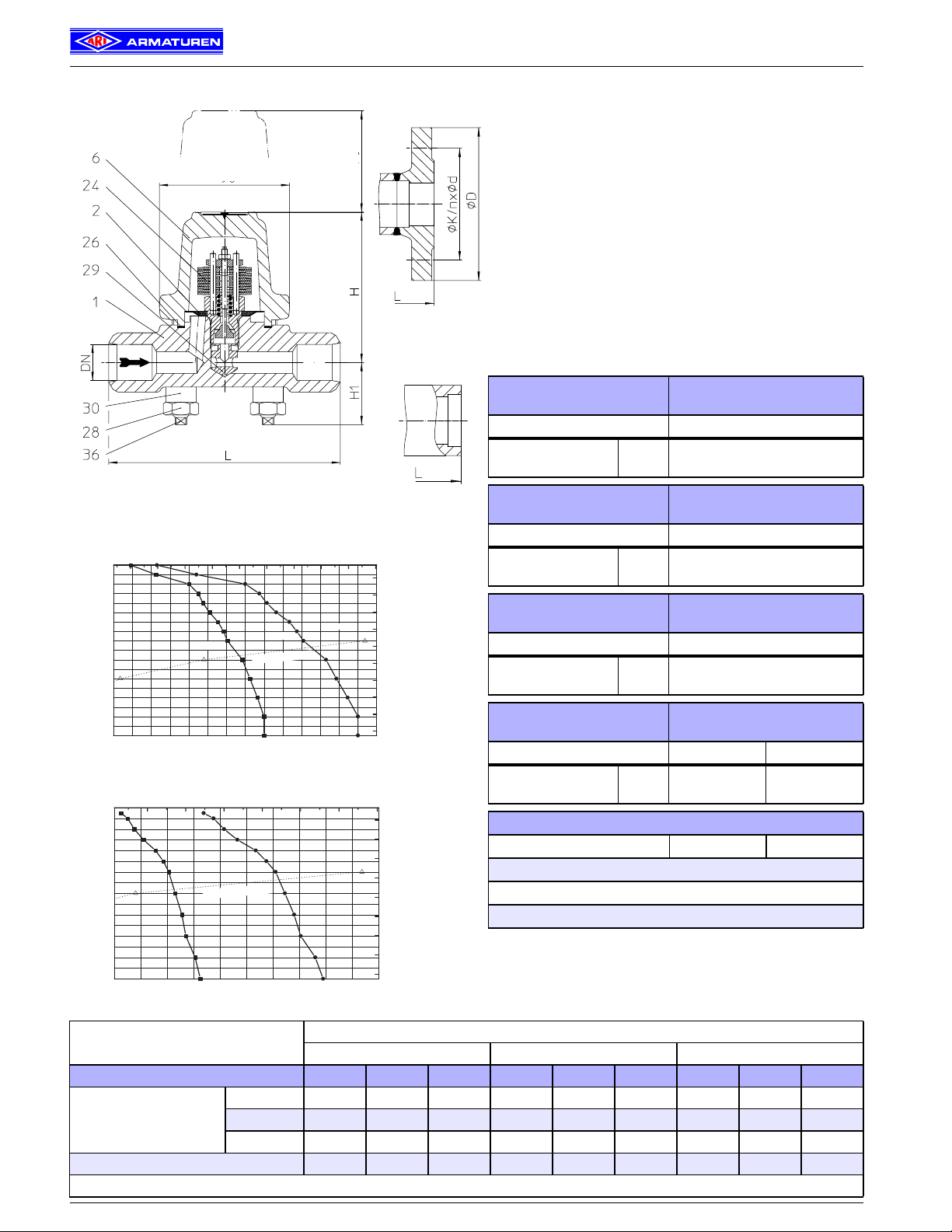
Series 600 - ANSI 400 / 600, size 1/2“ - 1“
High pressure - Bimetallic steam trap made of high temperature steel
•Bimettallicsteamtrapwith corrosion resistant andwaterhammerproof
bimetallic controller
• Automatic ventilation during start up and operation of the plant
• Integrated check valve
• Integrated strainer
• Installation with cover facing up-or sidewards
• Subcooling of condensate is continuously adjustable
(observe the operation instructions)
• The exchange of the controller is possible without disturbing the pipe
connections
• Controller at ANSI 600 available for operating range:
Sq.3.54“
2.76“
Fig. 600....1
with flanges
CONA® B
- Controller R60 - up to 870 psi inlet pressure
- Controller R90 - up to 1203 psi inlet pressure
ANSI 400 Fig. 86.600
SA 182 F12
Operating limits
Max. temperature (°F) 816
Fig. 600....4 butt welded ends
20 30 40 50 60 70 80 90 100
1000
900
800
700
˚F
600
ture
ra
500
e
p
400
Tem
300
200
100
200 400 600 800 1000 1200 1400
Working Pressures psig ; Material: SA182F12
50 60 70 80 90 100
875
800
700
600
˚F
ture
ra
Tempe
CL400
500
400
300
200
100
600 800 1000 1200 1400
Working Pressures psig ; Material: SA182F1
Working Pressures barg
CL400
(Operating Limits ASME B16.34 STANDARD CLASS)
Working Pressures barg
(Operating Limits ASME B16.34 STANDARD CLASS)
Ste
t
m sa
a
Steam saturation curve
CL600
ion curve
t
a
ur
Dimensions and weights
CL600
Steam
Water
Controller unit
permissible ∆P (psi)
Fig. 600....3
socket welded ends
ANSI 400 Fig. 86.600
SA 182 F1
Max. temperature (°F) 816
Steam
Water
110
1600
500
450
400
350
˚C
300
ure
t
ra
250
e
p
200
Tem
150
100
50
Controller unit
permissible ∆P (psi)
ANSI 600 Fig. 87.600
SA 182 F12
Max. temperature (°F) 905
Controller unit
permissible ∆P (psi)
ANSI 600 Fig. 87.600
SA 182 F1
Max. temperature (°F) 875 566
Controller unit
110
1600
450
400
350
300
˚C
ure
t
250
200
Tempera
150
100
50
permissible ∆P (psi)
Types of connection
Flanges ....1
Socket weld ends ....3
Butt weld ends ....4
Other types of connection on request.
Types of connection
Flanges Socket weld ends Butt weld ends
Sizes
1/2“ to 1“
Sizes
1/2“ to 1“
Sizes
1/2“ to 1“
Sizes
1/2“ to 1“
Operating limits
Operating limits
Operating limits
R60
870
ANSI 400/600 RF
R46
667
R46
667
R60
870
R90
1203
ANSI 600 RF
Size 1/2“ 3/4“ 1“ 1/2“ 3/4“ 1“ 1/2“ 3/4“ 1“
L * 8.27 8.27 9.06 6.30 6.30 6.30 6.30 6.30 6.30
Dimensions (in)
H 4.09 4.09 4.09 4.09 4.09 4.09 4.09 4.09 4.09
H1 1.65 1.65 1.65 1.65 1.65 1.65 1.65 1.65 1.65
Weight approximate (lb) 13.7 14.3 20.5 10.1 9.9 9.7 10.1 9.9 9.7
* other face-to-face dimensions on request For standard flange dimensions refer to page 12 larger sizes (ANSI600) refer to page 6
4 Edition 10/04 - Data subject to alteration
Page 5

Series 600 - ANSI 400 / 600, size 1/2“ - 1“
Parts
Pos. Description
1 Body SA 182 F12 SA 182 F1
2 Strainer * SA 240 Gr. 304
6 Cover SA 182 F12 SA 182 F1
24 Controller * corrosion resistant bimetal TB 102 / 85
26 Body-gasket * CrNi laminated both sides with pure graphite
28 Hexagonal nuts SA 193 Gr. 4
29 Erosion deflector * AISI 431
30 Extension sleeve SA 193 Gr. B16
36 Studs SA 193 Gr. B16
* Spare parts Design parameters acc. ASME B16.34
Capacity chart ANSI 400 (PN63)
Material codes
ASTM / AISI
1)
1)
CONA® B
1)
with metric screw-thread
Capacity chart ANSI 600 (PN100)
Capacity chart
The capacity chart shows the maximum flow at factory setting.
(Other factory settings for the sub-cooling on request.)
Curve 1
Maximum flow rate of condensate at factories setting about
approx.∆T 15 K / 27°F below saturation temperature.
Curve 2
Maximum flow rate of condensate sub-cooling at∆T approx. 30 K /
54°F.
Curve 3
Maximum flow rate of condensate at about 68°F (cold start-up).
The condensate temperature determines the opening of the
controller. The capacity increases with sub-cooling of the condensate.
Edition 10/04- Data subject to alteration 5
Page 6

Bimetallic steam trap made of high temperature steel
Sq.4.33“
3.54“
CONA® B
Series 600 - ANSI 400, size 1 1/2“ - 2“
• Bimetallic steam trap with corrosion resistant and waterhammerproof
bimetallic controller
• Automatic ventilation during start up and operation of the plant
• Integrated check valve
• Integrated strainer
• Installation with cover facing up-or sidewards
• Adjustable subcooling of factory setting
(see operation instructions)
• The exchange of the controller is possible without disturbing the pipe
connections
• Controller available for operating range:
- Controller R56 - up to 812 psi inlet pressure
- Controller R32 - up to 464 psi inlet pressure
ANSI 400 Fig. 86.600
SA 182 F1
Operating limits
Max. temperature (°F) 875 572
Fig. 600....1 with flanges
Controller unit
permissible ∆P (psi)
Sizes
1 1/2“ to 2“
R32
464
R56
812
Types of connection
Flanges ....1 ANSI 600 RF
Socket weld ends ....3
Butt weld ends ....4
Fig. 600....3
socket welded ends
30 40 50
875
800
700
600
˚F
re
500
tu
ra
pe
400
m
Te
300
200
100
400 500 600 700 800 900
Working Pressures psig ; Material: SA182F1
Working Pressures barg
CL400
Steam saturation curve
(Operating Limits ASME B16.34 STANDARD CLASS)
Dimensions and weights
butt welded ends
60
Steam
Water
io
t
a
r
tu
a
s
m
a
te
S
Fig. 600....4
450
400
350
300
˚C
e
r
tu
250
ra
pe
200
m
Te
150
100
50
1000
e
rv
u
c
n
Flanges Socket weld ends Butt weld ends
Other types of connection on request.
Types of connection
Size 1 1/2“ 2“ 1 1/2“ 2“ 1 1/2“ 2“
Dimensions (in)
L * 10.24 11.81 5.12 8.27 9.84 9.84
H 5.67 5.67 5.67 5.67 5.67 5.67
Weight approximate (lb) 29.3 31.1 17.6 17.6 19.6 21.6
* other face-to-face dimensions on request For standard flange dimensions refer to page 12 smaller sizes refer to page 4
6 Edition 10/04 - Data subject to alteration
Page 7

Series 600 - ANSI 400, size 1 1/2“ - 2“
Parts
Pos. Description
1 Body SA 182 F1
2 Strainer * SA 240 Gr. 304
6 Cover SA 182 F1
24 Controller * corrosion resistant bimetal TB 102 / 85
26 Gasket (body/cover) * CrNi laminated both sides with pure graphite
28 Hexagonal nuts TF M12 SA 194 Gr. 4
30 Extension sleeves SA 193 Gr. B16
36 Screw pins L M12 SA 193 Gr. B16
* Spare parts Design parameters acc. ASME B16.34 other materials on request
Material codes
ASTM / AISI
1)
1)
CONA® B
1)
with metric screw-thread
Capacity chart
Capacity chart
The capacity chart shows the maximum flow for controller R56 and
R32 at factory setting.
(Other factory settings for the sub-cooling on request.)
Curve 1
Maximum flow rate of condensate at factories setting about 15 K /
27°F below saturation temperature.
Curve 2
Maximum flow rate of sub-cooled condensate at approx. 30 K / 54°F
below saturation temperature.
Curve 3
Maximum flow rate at cold condensate at about 68°F (cold start-up).
The condensate-temperature determines the opening of the control-
ler. The capacity increases with sub-cooling temperature of the condensate.
Edition 10/04- Data subject to alteration 7
Page 8

Series 600 - ANSI 900 / 1500, size 1/2“ - 1“
High pressure - Bimetallic steam trap made of high temperature steel
• Bimetallic steam trap with corrosion resistant and waterhammerproof
bimetallic controller
• Automatic ventilation during start up and operation of the plant
Sq.3.54“
2.76“
• Integrated check valve
• Integrated strainer
• Installation with cover facing up-or sidewards
• Subcooling of condensate is continuously adjustable
(observe the operation instructions)
• The exchange of the controller is possible without disturbing the pipe
connections
CONA® B
ANSI 900 Fig. 88.600
SA 182 F12
Operating limits
Max. temperature (°F) 750
Controller unit
permissible ∆P (psi)
ANSI 900 Fig. 88.600
SA 182 F22
Sizes
1/2“ to 1“
R130
1595
Operating limits
Max. temperature (°F) 750
Fig. 600....4 butt welded ends
Controller unit
permissible ∆P (psi)
ANSI 1500 Fig. 89.600
SA 182 F22
Sizes
1/2“ to 1“
R130
1595
Operating limits
Max. temperature (°F) 909
Controller unit
permissible ∆P (psi)
Sizes
1/2“ to 1“
R150
2175
Types of connection
Flanges ....1 ANSI 900 RF ANSI 1500 RF
Socket weld ends ....3
Fig. 600....1
with flanges
50 60 70 80 90 100 110 120 130 140 150
1000
900
800
700
˚F
600
ure
t
a
r
500
e
p
m
400
e
T
300
200
100
600 800 1000 1200 1400 1600 1800 2000 2200
Working Pressures psig ; Material: SA182F12
Working Pressures barg
CL900
saturation curve
eam
t
S
(Operating Limits ASME B16.34 STANDARD CLASS)
Dimensions and weights
Fig. 600....3
socket welded ends
160
500
450
2400
400
350
300
250
200
150
100
50
Steam
Water
Flanges Socket weld ends Butt weld ends
1000
900
800
˚C
ure
t
ra
e
p
m
e
T
700
˚F
600
ure
t
a
r
500
e
p
m
400
e
T
300
200
100
Butt weld ends ....4
Other types of connection on request.
50 100 150 200
800 1200 1600 2000 2400 2800 3200
Working Pressures psig ; Material: SA182F22
Working Pressures barg
CL900
(Operating Limits ASME B16.34 STANDARD CLASS)
CL1500
Steam saturation curve
Steam
Types of connection
Water
3600
250
500
450
400
350
˚C
300
ure
t
ra
250
e
p
m
e
200
T
150
100
50
Size 1/2“ 1“ 1/2“ 3/4“ 1“ 1/2“ 3/4“ 1“
L * 8.27 9.06 6.30 6.30 6.30 6.30 6.30 6.30
Dimensions (in)
H 4.09 4.09 4.09 4.09 4.09 4.09 4.09 4.09
H1 1.65 1.65 1.65 1.65 1.65 1.65 1.65 1.65
Weight approximate (lb) 14.1 21.2 10.6 10.4 10.1 10.6 10.4 10.1
* other face-to-face dimensions on request For standard flange dimensions refer to page 12
8 Edition 10/04 - Data subject to alteration
Page 9

CONA® B
Series 600 - ANSI 900 / 1500, size 1/2“ - 1“
Parts
Material codes
Pos. Description
1 Body SA 182 F12
2 Strainer * SA 240 Gr. 304 SA 240 Gr. 304
6 Cover SA 182 F12 SA 182 F22
24 Controller * corrosion resistant bimetal TB 102 / 85 corrosion resistant bimetal TB 102 / 85
26 Gasket (body/cover) * CrNi laminated both sides with pure graphite CrNi laminated both sides with pure graphite
28 Hexagonal nuts
29 Erosion deflector * AISI 303 AISI 303
30 Extension sleeves SA 193 Gr. B16 SA 193 Gr. B16
32 Clamping sleeve * AISI 303 AISI 303
36 Studs
* Spare parts Design parameters acc. ASME B16.34
ASTM / AISI
(ANSI 900)
SA 193 Gr. B16
SA 193 Gr. B16
ASTM / AISI
(ANSI 1500)
SA 182 F22
(SA 182 F91 on request)
1)
1)
SA 193 Gr. B16
SA 193 Gr. B16
1)
1)
1)
with metric screw-thread
Capacity chart ANSI 900
Capacity chart ANSI 1500
Capacity chart
The capacity chart shows the maximum flow of hot and cold condensate at factoy setting.
(Other factory settings for the condensate sub-cooling on request.)
Curve 1
Maximum flow rate of hot condensate at approx. 10 K / 18°F below
saturation temperature.
Curve 2
Maximum flow rate of hot condensate at approx. 30 K / 54°F below
saturation temperature.
Curve 3
Maximum flow rate of condensate at about 68°F (cold start-up).
Edition 08/05 - Data subject to alteration
9
Page 10

Series 600 - ANSI 2500, size 1/2“ - 1“
High pressure - Bimetallic steam trap made of high temperature steel
• Bimetallic steam trap with corrosion resistant and water hammer proof
bimetallic controller
• Automatic ventilation during start up and operation of the plant
3.74“
• Integrated check valve
• Integrated strainer
• Installation with cover facing up-or sidewards
• Subcooling of condensate is continuously adjustable
(observe the operation instructions)
• The exchange of the controller is possible without disturbing the pipe
connections
CONA® B
Fig. 600....4 butt welded ends
Fig. 600....1
flanged
100 150 200 250 300 350
1100
1000
900
800
Steam
700
˚F
re
600
tu
ra
500
pe
m
Te
400
300
200
100
tu
a
s
m
a
te
S
Water
1000 1500 2000 2500 3000 3500 4000 4500 5000 5500 6000
Working Pressures psig ; Material: SA182F22
Working Pressures barg
CL2500
e
v
r
u
c
n
tio
a
r
(Operating Limits ASME B16.34 STANDARD CLASS)
Fig. 600....3
socket welded ends
400
550
500
450
400
˚C
350
re
u
t
300
ra
e
p
250
m
Te
200
150
100
50
6500
ANSI2500 Fig. 8c.600
SA 182 F22
Max. temperature (°F) 873
Controller unit
permissible ∆P (psi)
Sizes
1/2“ to 1“
ANSI 2500 Fig. 8c.600
SA 182 F91
Max. temperature (°F) 873
Controller unit
permissible ∆P (psi)
Sizes
1/2“ to 1“
Types of connection
Flanges ....1 ANSI 2500 RF
Socket weld ends ....3 DIN EN 12670, ANSI B16.11
Butt weld ends ....4 DIN EN 12627, ANSI B16.25
Other types of connection on request.
150 200 250 300 350
1100
1000
900
800
Steam
700
˚F
e
r
600
tu
ra
500
pe
m
Te
400
300
200
100
r
tu
a
s
m
a
te
S
Water
2000 2500 3000 3500 4000 4500 5000 5500 6000
Working Pressures psig ; Material: SA182F91
Working Pressures barg
CL2500
e
v
r
u
c
n
o
ti
a
(Operating Limits ASME B16.34 STANDARD CLASS)
400
Operating limits
R270
3915
Operating limits
R270
3915
550
500
450
400
˚C
350
e
r
tu
300
pera
250
m
Te
200
150
100
50
6500
Dimensions and weights
Flanges Socket weld ends Butt weld ends
Types of connection
Size 1/2“ 1“ 1/2“ 1“ 1/2“ 1“
L * 17.13 18.50 12.99 12.99 12.99 12.99
Dimensions (in)
H 5.32 5.32 5.32 5.32 5.32 5.32
H1 2.48 2.48 2.48 2.48 2.48 2.48
Weight approximate (lb) 59.5 72.8 44.1 41.9 44.1 41.9
* other face-to-face dimensions on request For standard flange dimensions refer to page 12.
10
Edition 09/05 - Data subject to alteration
Page 11

CONA® B
Series 600 - ANSI 2500, size 1/2“ - 1“
Parts
Pos. Description
1 Body SA 182 F22 SA 182 F91
2 Strainer * SA 240 Gr.304 SA 240 Gr.304
6 Cover SA 182 F22 SA 182 F91
24 Controller * corrosion resistant bimetal TB 102 / 85 corrosion resistant bimetal TB 102 / 85
26 Gasket (body/cover) * Spiral-wound gasket Spiral-wound gasket
28 Hexagonal nuts SA 453 Gr. 660 b
29 Erosion deflector * AISI 303 AISI 303
31 Baffle straightener AISI 440 AISI 440
32 Clamping sleeve * AISI 303 AISI 303
36 Studs SA 453 Gr. 660 b
* Spare parts Design parameters acc. ASME B16.34
Material codes
ASTM / AISI ASTM / AISI
1)
1)
SA 453 Gr. 660 b
SA 453 Gr. 660 b
1)
with metric screw-thread
1)
1)
Capacity chart ANSI 2500
Capacity chart
The capacity chart shows the maximum flow rate of hot and cold condensate at factoy setting.
(Other factory settings for the condensate sub-cooling on request.)
Curve 1
Maximum flow rate of hot condensate at approx. 10 K / 18°F below
saturation temperature.
Curve 2
Maximum flow rate of hot condensate at approx. 30 K / 54°F below
saturation temperature.
Curve 3
Maximum flow rate at cold condensate at about 68°F
(cold start-up).
Edition 08/05 - Data subject to alteration
11
Page 12
CONA® B
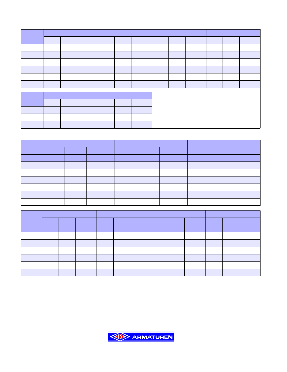
Flange dimension
Flange dimensions (DIN)
Size
1/2“ 3.74 2.56 4 x 0.55 3.74 2.56 4 x 0.55 4.13 2.95 4 x 0.55 4.13 2.95 4 x 0.55
3/4“ 4.13 2.95 4 x 0.55 4.13 2.95 4 x 0.55 -- -- -- -- -- --
1“ 4.53 3.35 4 x 0.55 4.53 3.35 4 x 0.55 5.51 3.94 4 x 0.71 5.51 3.94 4 x 0.71
1 1/4“ 5.51 3.94 4 x 0.71 5.51 3.94 4 x 0.71 -- -- -- -- -- --
1
1/2“ 5.91 4.33 4 x 0.71 5.91 4.33 4 x 0.71 6.69 4.92 4 x 0.87 6.69 4.92 4 x 0.87
2“ 6.50 4.92 4 x 0.71 6.50 4.92 4 x 0.71 7.09 5.31 4 x 0.87 7.68 5.71 4 x 1.02
PN 16 bar PN 40 bar PN 63 bar PN 100 bar
∅ D ∅ K n x ∅ d1 ∅ D ∅ K n x ∅ d1 ∅ D ∅ K n x ∅ d1 ∅ D ∅ K n x ∅ d1
Size
1/2“ 5.12 2.95 4 x 0.55 130 90 4 x 18
PN 160 bar PN 250
∅ D ∅ K n x ∅ d1 ∅ D ∅ K n x ∅ d
1“ 5.91 3.94 4 x 0.71 -- -- --
2“ 7.68 5.71 4 x 1.02 150 105 4 x 22
Flange dimensions (ANSI)
Size
∅ D ∅ K n x ∅d ∅ D ∅ K n x ∅d ∅ D ∅ K n x ∅d
ANSI 150 ANSI 300 ANSI 400
in in in in in in in in in in
1/2“ 3.50 2.36 4 x 0.62 3.75 2.62 4 x 0.62 3.75 2.62 4 x 0.62
3/4“ 3.90 2.70 4 x 0.62 4.62 3.25 4 x 0.75 4.62 3.25 4 x 0.75
1“ 4.25 3.10 4 x 0.62 4.88 3.50 4 x 0.75 4.88 3.50 4 x 0.75
1
1/4“ 4.62 3.50 4 x 0.62 5.25 3.88 4 x 0.75 -- -- --
1 1/2“ 5.00 3.85 4 x 0.62 6.12 4.50 4 x 0.88 -- -- --
2“ 6.00 4.76 4 x 0.75 6.50 5.00 8 x 0.75 -- -- --
Size
∅ D ∅ K n x ∅d ∅ D ∅ K n x ∅d ∅ D ∅ K n x ∅d ∅ D ∅ K n x ∅d
ANSI 600 ANSI 900 ANSI 1500 ANSI 2500
in in in in in in in in in in in in in
1/2“ 3.75 2.62 4 x 0.62 4.75 3.25 4 x 0.88 4.75 3.25 4 x 0.88 5.25 3.50 4 x 0.88
3/4“ 4.62 3.25 4 x 0.75 5.12 3.50 4 x 0.88 5.12 3.50 4 x 0.88 5.5 3.75 4 x 0.88
1“ 4.88 3.50 4 x 0.75 5.88 4.00 4 x 1.0 5.88 4.00 4 x 1.0 6.25 4.25 4 x 1.0
1 1/4“ 5.25 3.88 4 x 0.75 6.25 4.38 4 x 1.0 -- -- -- -- -- --
1
1/2“ 6.12 4.50 4 x 0.88 7.00 4.88 4 x 1.12 -- -- -- -- -- --
2“ 6.50 5.00 8 x 0.75 8.50 6.50 8 x 1.0 -- -- -- -- -- --
Steam traps according to ASTM
• Pressure bearing parts made of ASTM / AISI -materials
• Studs and nuts made of ASTM-materials, but metric screw-threads
• Face-to-face acc. to data sheet resp. customer request
• Flanges acc. to ANSI
• Pressure test acc. to API 598
Technology for the Future.
GERMAN QUALITY VALVES
Phone 713.947.3622 Fax 713.947.3635, Internet: http://www.ari-armaturen.com E-mail: scris@usa.ari-armaturen.com
ARI-Armaturen, USA Inc., 9363 Winkler Drive, Suite A, Houston, Texas 77017, USA, ,
12 Edition 10/04 - Data subject to alteration
 Loading...