

Page 1

SIMPLEX BASKET STRAINER
TITAN
BS5565-1212
f
FLANGED ENDS - FLAT FACE
TITAN FLOW CONTROL, INC.
ANSI CLASS 125
f
CAST IRON
f
CLAMPED & BOLTED COVER
MODELS: BS 55-CI
FEATURES
F
s
v e r s a t i l e - h i g h q u a l i t y d e s i g n
t h i s b a s k e t s t r a i n e r i s a v a i l a b l e w i t h e i t h e r a f u l l r a t e d b o l t e d
c o v e r (b s 65) o r c l a m p e d c o v e r (b s 55). b o t h m o d e l s a r e e p o x y p a i n t e d
a n d c o m e s t a n d a r d w i t h a p l u g g e d s i d e d r a i n c o n n e c t i o n . l a r g e r
s i z e s (8" ~ 20") a l s o f e a t u r e r e m o v a b l e
s
m i n i m a l p r e s s u r e l o s s
p r e s s u r e l o s s i s m i n i m i z e d b y prov idi ng a s l a n t e d s t r a i n i n g e l e m e n t
d e s i g n , a s t r a i g h t -t h r o u g h f l o w p a t h , a n d a l a r g e o p e n a r e a r a t i o .
i n l e t a n d o u t l e t b o s s e s a r e p r o v i d e d t o fa ci litat e t h e m o u n t i n g o f
p r e s s u r e g a u g e s t o m o n i t o r p r e s s u r e l o s s .
s
l a r g e s t r a i n i n g c a p a c i t y
w i t h i t s l a r g e b o d y a n d s i z e a b l e s t r a i n i n g e l e m e n t , t h i s b a s k e t
s t r a i n e r h a s t h e abi li t y t o s t o r e l a r g e q u a n t i t i e s o f d e b r i s w i t h o u t
a f f e c ti ng p r e s s u r e l o s s - t h u s m a x i m i z i n g t i m e b e t w e e n serv ici ng.
s
n u m e r o u s s t r a i n i n g e l e m e n t o p t i o n s
s t r a i n i n g e l e m e n t s a r e a v a i l a b l e in a v a r i e t y o f p e r f o r a t i o n s , m e s h e s ,
a n d m a t e r i a l s . s p e c i a l d e s i g n s a r e a l s o a v a i l a b l e i n c l u d i n g m a g n e t i c ,
w e d g e w i r e , d r i l l e d p e r f o r a t i o n s , a n d p l e a t e d s t r a i n i n g e l e m e n t s .
t h e s t a n d a r d m a t e r i a l f o r s t r a i n i n g e l e m e n t s is t y p e 304 s ta in le ss s t e e l .
s
s e l f -c l e a n i n g o p t i o n
uti li z in g a m odi fi e d s t r a i n i n g e l e m e n t , t h e b o t t o m d r a i n c a n b e f i t t e d
w i t h a t i t a n f c i b a l l v a l v e t o a l l o w f o r t h e a u t o m a t i c c l e a n i n g o r
f l u s h i n g o f t h e s t r a i n i n g e l e m e n t w h i l e k e e p i n g t h e p i p e l i n e in s e r v i c e .
(c l a m p e d c o v e r )
BS 65-CI
(b o l t e d c o v e r )
sizes: 2" ~ 20"
a d j u s t a b l e l e g b r a c k e t s .
/
BS 55-CI is shown with clamp cover
and removable leg brackets
Side drain is standard, an optional
bottom drain is available
TECHNICAL
T
pressure/ temperature rating
cast iron astm a126 gr. b - class 125
BS 55-CI (Clamped Cover) (2” ~ 12”)
WOG (Non-shock): 200 PSI @ 100 °F
Saturated Steam: Not Recommended
Maximum Liquid: Not Recommended
BS 65-CI (Bolted Cover) (2” ~ 12”)
(Non-shock): 200 PSI @ 150 °F
WOG
Saturated Steam: 125 PSI @ 353 °F
Maximum Liquid: 125 PSI @ 450 °F
BS 55-CI (Clamped Cover) (14” ~ 20”)
(Non-shock): 100 PSI @ 100 °F
WOG
Saturated Steam: Not Recommended
Maximum Liquid: Not Recommended
BS 65-CI (Bolted Cover) (14” ~ 20”)
(Non-shock): 150 PSI @ 150 °F
WOG
Saturated Steam: 100 PSI @ 353 °F
Maximum Liquid: 100 PSI @ 353 °F
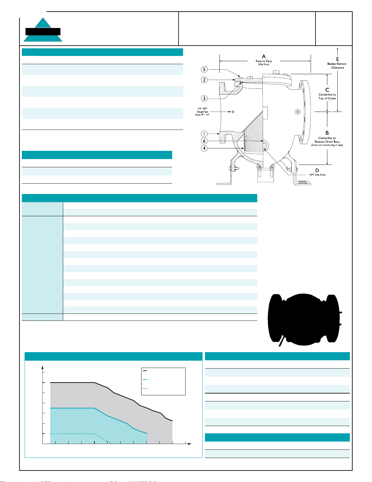
A
m a r k e t s : w a t e r & w a s t e w a t e r , p u l p & p a p e r , c h e m i c a l & p e t r o c h e m i c a l , p e t r o l e u m , o i l & g a s , t r a n s p o r t a t i o n ,
m a r i n e i n d u s t r y , a n d f o o d i n d u s t r y
g e n e r a l a p p l i c a t i o n : s i m p l e x b a s k e t s t r a i n e r s a r e i n s ta l l e d i n t o a p i p e l i n e s y s te m t o r e m o v e u n w a n t e d
d e b r i s f r o m t h e p i p e l i n e f l o w . b a s k e t s t r a i n e r s a r e c o m m o n l y u s e d in h o r i z o n t a l p i p e l i n e s w h e r e d e b r i s
l o a d i n g is h i g h a n d t h e c o l l e c t i o n o f s o l i d s i s r e q u i r e d . s t r a i n i n g is a c c o m p l i s h e d v i a a p e r f o r a t e d o r
m e s h l i n e d s t r a i n i n g e l e m e n t , i n t e r n a l t o t h e b a s k e t s t r a i n e r . i n g e n e r a l , t h e s i z e o f t h e p e r f o r a t i o n o r
m e s h s h o u l d b e s l i g h t l y s m a l l e r t h a n t h e s m a l l e s t d e b r i s p a r t i c l e t o b e r e m o v e d . i t i s i m p o r t a n t t o n o t e
t h a t t h e c o r r e c t s i z e o f a b a s k e t s t r a i n e r is d e t e r m i n e d b y i t s j o b f u n c t i o n , n o t b y t h e s i z e o f t h e p i p e l i n e .
APPLICATIONS
Th e ab ove data rep rese nt s co mm on m ar ket an d se rv ice appli ca ti on s. No re pres en ta ti on o r gu ar an te e, exp ress ed o r im pl ie d, is g ive n due to t he n um er ou s va ri ati ons
of concentrations, temperatures and flow conditions that may occur during actual ser vice.
TITAN FLOW CONTROL, INC .
YOUR PIPELINE TO THE FUTURE!
Tel: 910-735-0000
290 Corporate Drive
s
Fax: 910-738-3848
s
s
titan@titanfci.com
PO Box 7408
s
s
Lumberton, NC 28358
www.titanfci.com
Page 2
BS5565-1212
TITAN
Temperature(F)°
Pressure (PSI)
-50050 100 150 200 250 300 350 400 450 500
80
100
120
140
160
180
200
220
SOURCE: ASME/ANSI B16.1-1998
2” ~ 12”
A126 Gr. B ANSI Class 125
14” ~ 20” BS 65 (Bolted)
A126 Gr. B ANSI Class 125
14” ~ 20” BS 55 (Clamp)
A126 Gr. B ANSI Class 125
TITAN FLOW CONTROL, Inc.
290 Corporate Drive E-mail: titan@titanfci.com
Lumberton, NC 28358 Web: www.titanfci.com
Tel: 910.735.0000 Fax: 910.738.3848
BILL OF MATERIALS
No. PART BS 65-CI BS 55-CI
1 Body
(2)
2 Cover Cast Iron ASTM A126 Gr. B
3 Cover Gasket
(3)
4 Straining Element
Non-Asbestos - BS65 Buna-N O-Ring - BS55
(3)
5 Cap Screws Zinc Plated Carbon Steel
(1)
Cast Iron ASTM A126 Gr. B
Type 304 Stainless Steel
SIMPLEX BASKET STRAINER
BS 55-CI - (Clamped Cover)
BS 65-CI - (Bolted Cover)
Flanged Ends • Flat Face • Cast Iron Body
ANSI
Class 125
6 Plugs
(Boss/Drain) Cast Iron
1. Equivalent or better materials may be substituted at the manufacturer's discretion.
2. Cast Iron bodies are epoxy painted.
3. Denotes recommended spare parts.
standard screen selections
Size Liquid Open Area Steam Open Area
2" ~ 4" 1/16 (.0625) 41% 3/64 (.045) 36%
5" ~ 12" 1/8 (.125) 40% 3/64 (.045)
(1)
36%
BS 65 with
Bolted Cover
Side drain is standard.
Optional bottom drain
is available.
1. For 10" and above, consult factory on screen selections for steam.
(1)
SIZE
A DIMENSION
FACE TO FACE
B DIMENSION
CTR. LINE TO BOTTOM
C DIMENSION
CTR. LINE TO TOP
D DIMENSION
NPT BLOW-OFF
E DIMENSION
SCREEN REMOVAL
ASSEMBLED
WEIGHT (BS65)
ASSEMBLED
WEIGHT (BS55)
FlowCoefcient
DIMENSIONS AND PERFORMANCE DATA
in 2 2 1/2 3 4 5 6 8 10 12 14 16 20
mm 50 65 80 100 125 150 200 250 300 350 400 500
(2)
in 8.625 7.562 8.75 11.25 12.25 14.00 17.125 22.00 25.25 29.00 31.875 36.49
mm 220 193 223 286 311 356 435 559 642 737 810 927
(3)
in 4.88 5.12 4.63 7.00 7.88 8.00 11.38 14.12 20.25 30.00 36.66 38.44
mm 124 130 118 178 200 204 289 359 515 762 931 976
in 3.83 3.75 5.125 5.375 4.75 7.00 8.00 8.82 10.32 15.00 16.00 15.75
mm 97 96 131 137 121 178 203 224 262 381 406 400
in 1/2 3/4 3/4 1 1 1 1/4 1 1/2 1 1/2 2 2 2 2
mm 15 20 20 25 25 32 40 40 50 50 50 50
in 10.875 10.875 11.25 15.50 15.50 18.25 23.375 27.50 35.00 45.00 55.00 65.00
mm 277 277 286 394 394 464 594 699 889 1143 1397 1651
lb 27.0 30.0 40.0 64.0 84.0 142.0 244.0 416.0 732.0 992 1735 C/F
kg 12.2 13.6 18.1 29.0 38.1 64.4 110.6 188.5 332.0 450.0 787.0 C/F
lb 31.0 34.0 42.0 81.0 84.0 150.0 275.0 436.8 768.0 1246 C/F C/F
kg 14.0 15.4 19.0 36.7 38.1 68.0 124.7 197.8 348.4 565.2 C/F C/F
C
43 86 135 290 490 780 1600 3250 5200 8000 10000 16500
v
1. Dimensions,weights,andowcoefcientsareprovidedforreferenceonly.Whenrequiredrequestcertieddrawings.
2. Face to face values have a tolerance of ±0.06 in (±2.0 mm) for sizes 10" and lower and a tolerance of ±0.12 in (±3.0 mm) for sizes
12" and larger.
3. Removable/adjustable leg brackets are standard on sizes 8" through 20". Centerline to bottom dimension does not include
removablelegs,whichcanextendapproximatelythreetoveinchesbeyondthebottombossdrain.
Additional Design & Technical Notes:
Inlet• and outlet bosses are standard on sizes 8"
through 14".
Inlet• and outlet 1/4" NPT gauge taps with plugs
are standard on sizes 8" through 14".
1/4"• cover vent taps with plugs are standard on
sizes 8" through 20".
Straining• element features a bow shaped
handle that presses against the cover to help
ensure the straining element remains securely
seated during operation.
Clamped • cover design:
Sizes 2" ~ 4" are designed with (1) Tee Bolt
Size 6" is designed with (2) Tee Bolts
Sizes 8" ~ 16" are designed with (4) Tee Bolts
Size 20" is designed with (6) Tee Bolts
PRESSURE - TEMPERATURE RATINGS
Titan FCI makes every effort to ensure the information presented on our literature accurately reects exact product specications. However, as product changes occur, there may be short-term differences between actual product
specications and the information contained within our literature. Titan FCI reserves the right to make design and specication c hanges to improve our products without prior notication. When required, request certied drawings.
pressure - temperature rating
ANSI CLASS 125 BS 65-CI (2 ~ 12") BS 55-CI (2 ~ 12")
WOG
(Non-shock) 200 PSI @ 150 °F 200 PSI @ 100 °F
Saturated Steam
Max Liquid
125 PSI @ 353 °F Not Recommended
125 PSI @ 450 °F Not Recommended
ANSI CLASS 125 BS 65-CI (14 ~ 20") BS 55-CI (14 ~ 20")
WOG
(Non-shock) 150 PSI @ 150 °F 100 PSI @ 100 °F
Saturated Steam
Max Liquid
100 PSI @ 353 °F Not Recommended
100 PSI @ 353 °F Not Recommended
REFERENCED STANDARDS & CODES
CODE DESCRIPTION
ASME/ANSI B16.1 Cast Iron Pipe Flanges and Flanged Fittings
 Loading...