

Page 1

CONNECTORS
- 242 -
SERIES AUM
NEOPRENE NPT END CONNECTION
DOUBLE SPHERE CONNECTORS
Pressures to 150 PSIG (10.34 barg)
Temperatures to 230ºF (110ºC)
● For connection pipes and equipment where
threaded union ends are preferred
● Accommodates thermal movement and
misalignment
● Four way greater movements provide high level
of installation flexibility.
● Precision molded of synthetic rubber reinforced
with nylon cord.
● Excellent ability to absorb vibrations, sounds and
withstand high pressures.
● Easy to install.
M
ODELS
● AUM – NPT Connection
APPLICABLE CODES
● ASME/ANSI B1-20.1
APPLICA TIONS
● Process Industry
● Weak Acids
● Alkalies
● Compressed Air
● Pulp & Paper
● Oil & Gas
● Water & Waste
● Pump suction & discharge
● Chemical lines
0 2 0 0 - A U M
12345678
Inlet Size
Model
Dash
Series AUM Ordering Code
Dash - Position 5
Model - Position 6 -8
AUM - Twin Sphere,
NPT, CI, Neoprene
Inlet Size* - Position 1 - 4
0050 - 1/2"
0075 - 3/4"
0100 - 1"
0125 - 11⁄4"
0150 - 11⁄2"
0200 - 2"
PRESSURE/TEMPERATURE RATINGS
Pressure (psi)
Temperature (F)
Page 2
CONNECTORS
- 243 -
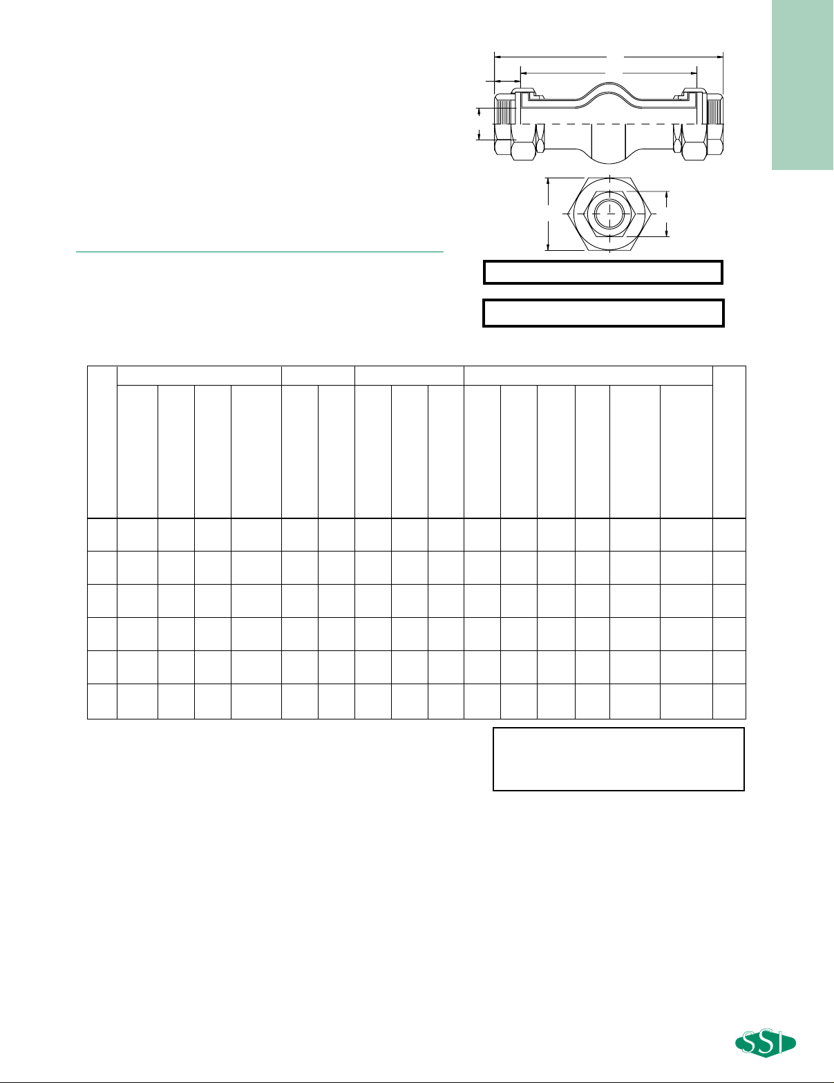
Connections: 1/2" to 2"
Dimensions are subject to change. Consult
factory for certified drawings when required.
SERIES AUM
NEOPRENE NPT END CONNECTION
DOUBLE SPHERE CONNECTORS
SPECIFICATION
Union End Connector body material shall be neoprene cover and
tube elastomer with nylon cord fabric reinforcement. The twin sphere
connector will have Cast Ductile Iron threaded union ends. The twin
sphere connector shall be SSI AUM Series.
M
ATERIALS OF CONSTRUCTION
Body ......................................................................Neoprene
Reinforcing Fabric ......................................Nylon Cord Fabric
Wire ..............................................................Hard Steel Wire
Threaded Union Ends ..................................Cast Ductile Iron
Installed Length Travel Allowable Movement Dimensions
1/2 8 711⁄32 81⁄8 75⁄16 71⁄8 87⁄32 7/8 1/4 7/8
32
29/32 63⁄32 17/32 11⁄16 111⁄16 1
(13) (203) (187) (206) (186) (181) (209) (22) (6) (22) (23) (155) (13) (27) (43) (0.5)
3/4 8 711⁄32 81⁄8 67⁄8 71⁄8 87⁄32 7/8 1/4 7/8
32
1529⁄32 3/4 111⁄32 131⁄32 1
(19) (203) (187) (206) (175) (181) (209) (22) (6) (22) (25) (150) (19) (34) (50) (0.5)
18711⁄32 81⁄8 65⁄8 71⁄8 87⁄32 7/8 1/4 7/8
25
13⁄16 517⁄32 1 1 5/8 21⁄2 2
(25) (203) (187) (206) (168) (181) (209) (22) (6) (22) (30) (140) (25) (41) (64) (0.9)
11⁄4 8711⁄32 81⁄8 65⁄8 71⁄8 87⁄32 7/8 1/4 7/8
25
13⁄16 517⁄32 11⁄4 131⁄32 227⁄32 3
(32) (203) (187) (206) (168) (181) (209) (22) (6) (22) (30) (140) (32) (50) (72) (1.5)
11⁄2 8711⁄32 81⁄8 65⁄8 71⁄8 87⁄32 7/8 1/4 7/8
20
13⁄8 51⁄8 117⁄32 21⁄4 323⁄32 4
(38) (203) (187) (206) (168) (181) (209) (22) (6) (22) (35) (130) (39) (57) (94) (2.0)
28711⁄32 81⁄8 65⁄8 71⁄8 87⁄32 7/8 1/4 7/8
15
2423⁄32 127⁄32 2 3/4 323⁄32 6
(51) (203) (187) (206) (168) (181) (209) (22) (6) (22) (40) (120) (47) (70) (94) (2.6)
DIMENSIONS inches (mm) AND WEIGHTS pounds (kg)
F
E
D
C
A
B
A
C
B
Size
Neutral Length
Minimum Installed
Maximum Installed
Recommended
Pipe Opening
Total Compressed
Total Extended
Axial Compression
Lateral Deflection
Angular Deflections
“B” Length of Fittings
“C” Length of Rubber
“D” Connector
Inner Diameter
“E” Width of Fitting
Hex Head
“F” Width of
Union Hex Head
Weight
D
F
E
Burst Pressure 570 PSIG
Installation Note:
For correct Installation & Maintenance
instructions
see page 244
 Loading...